

Abstract
In the basal ganglia (BG), anatomically segregated and topographically-organized feedforward circuits are thought to modulate multiple behaviors in parallel. Although topographically-arranged BG circuits have been described, the extent to which these relationships are maintained across the BG output nuclei and in downstream targets is unclear. Here, using focal transsynaptic anterograde tracing, we show that the motor-action related topographical organization of the striatum is preserved in all BG output nuclei. The topography is also maintained downstream of the BG and in multiple parallel closed loops that provide striatal input. Furthermore, focal activation of two distinct striatal regions induce either licking or turning, consistent with the structure of projections to targets outside the BG. Our results confirm the parallel model of BG function, and suggest that the integration and competition of information relating to different behavior occurs largely outside of the BG.
Keywords: Basal ganglia, striatum, substantia nigra reticulata, anterograde tracing, topography
Introduction
The basal ganglia (BG) are subcortical nuclei involved in decision making and motor control1–3. The striatum, the main input region of the BG sends projections to three output nuclei - the entopenducular nucleus (EP), globus pallidus externus (GPe) and substantia nigra pars reticulata (SNr). These nuclei, in turn, project to directly or indirectly to thalamus, superior colliculus, brain stem and other regions to influence behavior.
Two models of BG function predict radically different architectures and topographical organization of BG circuits and outputs. One model posits that BG circuits mediate learning of arbitrary stimulus-response associations4,5. In this model, stimulus identity is encoded in the input to striatum which activates specific striatal neurons that generate a specific behavior. If the behavior leads to a reward, dopamine is thought to reinforce that stimulus-response association6,7. In order for BG to be able to reinforce arbitrary stimulus-response associations, projections from striatum to BG output nuclei need to form an all-to-all connected network, allowing cross talk between each striatum pathway as necessary for contextual information to control any potential motor output. In contrast, a different model posits that each BG pathway controls only a specific set of behaviors8. In this model, each pathway remains anatomically segregated and innervates a unique set of target brain regions, endowing each BG pathway with exclusive control over specific aspects of behavior.
Anatomical evidence for both models exists. Studies in primates and rodents indicate that BG projections are topographically organized and subdivided into segregated anatomical pathways targeting different subsets of brain regions and premotor nuclei8–10. However, other evidence suggests that there is considerable convergence within the BG. Stimulation of distinct cortical regions that innervate distinct striatal subregions activates the same STN/SNr neurons, suggesting non-parallel organization within the BG11,12. In vivo, optogenetic activation of the direct pathway in a striatal subregion (e.g., dorsomedial striatum) can induce an array of different behaviors including locomotion, nose poke reinforcement, arm movement reinforcement, and visual detection modulation1,2,13–15. These studies support a model whereby a single BG pathway has access to an overlapping pool of premotor nuclei encoding different sets of actions. Thus, depending on the behavioral context, stimulating the same striatal region reveals categorically different behavioral phenotypes, highlighting the diverse behavioral functions a single BG pathway can carry out.
A difficulty in interpreting retrograde tracing experiments is the lack of specificity of the tracers. For instance, wildtype rabies virus does not specifically infect one projection. Given that striatum can target cortex via multiple routes (e.g. striatum→GPe→cortex; striatum→STN→cortex; striatum→SNr→thalamus→cortex), it may be difficult to determine, by solely using survival time of neurons after virus injection, which of these polysynaptic pathways is taken by cortically-injected rabies16–19. On the other hand, one potential caveat in interpreting most gain of function optogenetic studies in rodent striatum is the lack of anatomical specificity of the stimulation. Optogenetic activation is generally done by delivering high power light to a large volume widely expressing an activator protein (e.g. ChR2)1,2,14,15,20. In this regime, the effects of stimulation may arise from the region immediately below the fiber tip (usually the reported location of effect) or from a more distant region that expresses the activator opsin and is exposed to light21,22. Given this caveat, it is possible that the many phenotypes observed by attempting to stimulate a specific region of striatum might be a collection resulting from stimulating distinct and varying regions.
In order to avoid these caveats, we used a spatially-targeted approach to reveal the anatomical organization of the basal ganglia and the behavioral consequences of focally activating striatum in the mouse. Using a combination of focal anterograde tracing, slice electrophysiology, and spatially-precise optogenetic manipulations in vivo, we show that the outputs of the BG are subdivided into anatomically and functionally segregated pathways. Anatomically, SNr projections to the parafasciular nucleus, ventromedial thalamus, and superior colliculus are topographically organized. These three nuclei, in turn, project back to the striatal region from which they receive input, suggesting the existence of at least three closed BG loops. Using tapered optical fibers to optogenetically activate focal regions of striatum, we reveal functional maps for licking and locomotor turning, arising from ventrolateral striatum (VLS) and ventromedial/dorsomedial striatum (VMS and DMS, or MS), respectively. These two distinct striatal regions, via SNr, have access to the relevant cortical, collicular and brain stem regions involved in licking23,24 and orienting25,26, respectively. Activation of VLS modulates the activity of cortical and collicular regions involved in licking, consistent with the existence of a functional lick-controlling loop involving BG. Stimulation of striatal regions outside the VLS ‘lick zone’ did not interfere with mouse’s ability to make correct lick decisions for reward, supporting a parallel organization of motor-related BG outputs. Our results support a model of BG in which multiple segregated pathways project to distinct anatomical regions to control specific behaviors in parallel.
Results
Topographical organization of projections from striatum to BG output nuclei
We took advantage of the anterograde transsynaptic property of the adeno-associated viruses serotype 1 (AAV1) to investigate the topography of the BG circuitry27,28. Briefly, our strategy was to use a reporter mouse, Rosa26-Lox-STOP-Lox-H2B-EGFP (referred to as H2B-EGFP reporter mice) and inject AAV1 encoding Cre recombinase (AAV1-Cre) into a region of interest. Two weeks later, AAV1-Cre had travelled anterograde, entering a subset of postsynaptic cells and activating reporter expression. Thus, imaging EGFP in downstream regions allowed easy identification of cells postsynaptic to the AAV1-Cre infected ‘starter’ cells (Fig. 1a). We chose to examine three striatal regions that have been extensively studied - dorsomedial (DMS), dorsolateral (DLS) and ventrolateral (VLS) striatum. Previous studies that subdivided striatum based on clustering of cortical inputs also identified DMS, DLS and VLS as distinct striatal compartments29–31. We injected AAV1-Cre into one striatal subregion of the H2B-EGFP reporter mouse to activate nuclear GFP fluorescence on Cre expression. This resulted in labelled cells around the injection site and in downstream regions such as GPe, EP and SNr targeted by the axons of neurons at the injection site (Fig. 1b-c). We found that within GPe, EP and SNr, the location of anterogradely labelled cells depended on the location of the injection in striatum, indicating a topographical relationship between striatal subregions and output nuclei (Fig. 1c). Injections in multiple mice (n=3 per site) and calculation of the average cell density maps revealed a consistent pattern of projections to subregions within GPe, EP and SNr (Fig. 1c, Extended Data Fig. 1). Since the striatal direct pathway projects to all BG output nuclei, whereas the indirect pathway projects only to GPe, our results suggest that that both pathways arising from DMS, DLS and VLS maintain topography to all three BG output nuclei.
Figure 1. Topographically organized projection from BG input to output nuclei.

a) Experimental protocol for studying topography in the basal ganglia. top sagittal section, AAV1-Cre is injected into DMS, DLS, or VLS of H2B-EGFP reporter mice (Rosa26-CAG-LSL-H2B-mCherry mouse line). bottom coronal sections, After 2 weeks, the Cre encoded by the virus activates H2B-EGFP expression at the injection site (STR) as well as, due to its anterograde propagation, in the BG output nuclei (GPe – globus pallidus externus; EP – entopeduncular nucleus; SNr – substantia nigra pars reticulata).
b) Example coronal sections of striatum showing the injection sites (scale bar, 1mm) with fluorescence of the H2B-EGFP shown in indicated colors – DMS (magenta), DLS (cyan) and VLS (yellow). Similar results were obtained in n = 9 mice (n = 3 for each site).
c) Example coronal section (left column) and average relative cell density map of H2B-EGFP expressing cells (right column) in GPe (left), EP (middle) and SNr (right) for injections at three different striatal sites as indicated (top DMS, middle DLS, bottom VLS) (n=3 mice for each striatal injection site, scale bar, 500 μm).
Trans-synaptic anterograde tracing reveals topography downstream of BG
We examined whether the BG output projections remain segregated downstream of BG. We injected two AAV1 encoding different recombinases (Cre and Flpo) into medial and lateral striatum and then injected a mixture of AAVs, one that expresses a red fluorophore (tdTomato) in a Cre-dependent manner and one that expresses a green fluorophore (GFP) in a Flpo-dependent manner in downstream targets (GPe and SNr) (Fig. 2a, c). This allowed simultaneous examination of the target regions of the two striatal injection sites in each output structure as well as the distribution of the axons from the output structure subregions to their downstream targets. We used this strategy to examine the projections of medial and lateral striatum through the GPe and SNr to downstream regions. We injected a larger volume of AAV1-Cre than in the previous experiment (Fig. 1b) in order to label as many cells as possible in the downstream areas. This approach revealed BG pathways through GPe arising from inputs in medial or lateral striatum (MGPe or LGPe, respectively) (Fig. 2b). MGPe and LGPe axons targeted SNr, parafascicular nucleus (Pf), striatum and cortex, consistent with previous studies (Fig. 2b)17,32. Furthermore, in these targets, topographical organization was observed whereby MGPe innervated medial SNr, medial striatum, medial Pf, and limbic cortical regions, whereas LGPe innervated lateral SNr, lateral striatum, ventrolateral Pf, and sensorimotor cortical regions (Fig. 2b). A similar approach was used to investigate the topography downstream of SNr and EP (Fig. 2c, Extended Data Fig. 2). A medial-lateral topographical arrangement was observed downstream of SNr, in ventromedial thalamus (VM), Pf, superior colliculus (SC), zona incerta (ZI) as well as downstream of EP, in lateral habenula (LHb) (Figs. 2d, Extended Data Fig. 2-5).
Figure 2. Projections of BG output nuclei to downstream targets maintain segregated topography.

a) Protocol for tracing medial-lateral topography in GPe. AAV1-Cre and AAV1-Flpo were injected in the medial and lateral striatum, respectively, followed by injection in GPe of a mixture of AAVs encoding fluorophores whose expression is activated by either Cre (AAV-DIO-tdTom) or Flpo (AAV-fDIO-EYFP) recombinase. Anterograde movement of AAV1-Cre activates tdTom expression in the cells of medial striatum target zone of the GPe (MGPe) whereas AAV1-Flpo activates EYFP expression in the lateral striatum target zone (LGPe).
b) Example coronal sections showing fluorophore-expressing cell bodies in GPe (left) and labeled their axons downstream of the GPe (right three panels) in SNr, parafasicular nucleus (Pf), and striatum/cortex (STR/CTX) as indicated (scale bar, 1mm). Insets show enlarged images of the SNR, Pf, and CTX. Similar results were obtained in n = 2 mice.
c) Protocol as in panel a) but with Cre and Flpo dependent viruses injected in SNr to label the medial and lateral SNr target zones (MSNr and LSNr).
d) Example coronal sections showing the infected cell bodies in SNr (left) and their axon downstream of SNr (right three panels) in ventromedial thalamus (VM), Pf, and superior colliculus (SC) (scale bar, 1mm). Insets show enlarged images of the VM and Pf. Similar results were obtained in n = 4 mice.
e) Protocol for anterograde tracing from more localized, focal injections of AAV1-Cre into either DMS, DLS or VLS in separate mice, followed by a AAV-DIO-TdTom in SNr.
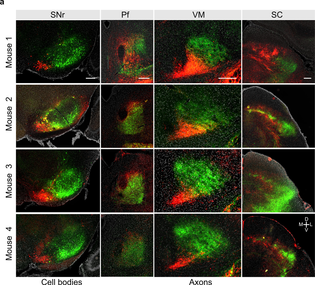
f) Example coronal sections showing the infected cell bodies in SNr (left column) and axons in Pf, VM, SC and brain stem (right four columns) for mice with AAV1-Cre injections into DMS, DLS, or VLS as indicated. Scale bar, 250 μm. IRt: intermediate reticular nucleus, PCRt: parvicellular reticular nucelus, Gi: gigantocellular reticular nucleus. Similar results were obtained in n = 9 mice (n = 3 for each site).
Given the fine-scale topographical organization that observed from DMS, DLS, or VLS to SNr (Fig. 1d), we hypothesized that a similar fine-scale topography might also exist downstream of SNr, with higher precision than what we observed for medial vs. lateral SNr projections (Fig. 2d). Labelling three pathways simultaneously in one mouse was challenging, due to a lack of a third recombinase that could work along with Cre and Flpo. Therefore, we focally injected AAV1-Cre in either DMS, DLS, or VLS in separate H2B reporter mice (as in the experiment described in Fig. 1) followed by AAV-DIO-TdTom into SNr. Crucially, we ensured that focal AAV1-Cre injections in the striatum did not invade neighboring regions. As expected, TdTom positive cells were observed in different parts of SNr, depending on the location of the AAV1-Cre injection in striatum. We quantified relative axonal density in the brain regions downstream of SNr for the three striatal injection sites (DMS, DLS and VLS, Fig. 2e, f, Extended Data Fig. 6). All SNr subregions targeted brain regions in a similar fashion, with heaviest innervation in VM/VA, SC and ZI. Axons in Pf, VM, SC and brainstem (IRt/PCRt and Gi) were topographically organized, similar to what was observed above (Fig. 2c-d), but at finer scale (Fig. 2f). Interestingly, in SC, DMS recipient SNr (DMSSNr) axons and DLS recipient SNr (DLSSNr) axons both innervate the medial part of SC, but close inspection revealed differential layer specificity (Extended Data Fig. 4), in a manner that segregated projections within medial SC, and similar to previous observations33. We also observed axons within striatum, representing putative dopamine neurons labelled via anterograde tracing. Axons within striatum overlapped with the striatal injection site, suggesting closed loops between striatum and midbrain dopaminergic centers (Extended Data Fig. 7a). In separate experiments, we confirmed that axons observed in striatum did not arise from non-dopaminergic SNr cells (Extended Data Fig. 7b-d). Overall, BG pathways starting from DMS, DLS and VLS maintained anatomical segregation outside of the BG.
SNr output forms closed and segregated loops via VM, Pf and SC
The thalamic nucleus Pf is one of the main glutamatergic input structures to striatum and its projection to striatum is topographically organized34. As the SNr output to Pf is also topographically organized, point-to-point closed BG loops through thalamus may exist. In order to verify the existence of closed and segregated BG loops via Pf, we re-examined sections containing Pf from experiments described above (Fig. 2e-f). We noticed that AAV1-Cre acted as both as an anterograde and retrograde tracer, consistent with the previous report27. This permitted examination of retrogradely labelled Pf cells that project to DMS, DLS or VLS, and anterogradely labelled SNr axons (DMSSNr, DLSSNr and VLSSNr) in Pf simultaneously (Fig. 3a). Consistent with the existence of closed and segregated loops, anterogradely selected SNr axons and retrogradely labeled Pf cells co-localized within Pf for all injections into DMS, DLS, and VLS (Fig. 3b).
Figure 3. The BG output via Pf forms segregated and closed loops.

a) Simultaneous mapping Pf input to striatum and BG output to Pf. AAV1-Cre injected into the H2B-EGFP reporter mouse travels retrogradely to label neurons in Pf that project to the injection site as well as anterogradely to labels neurons in SNr targeted by those in the injection site. AAV-DIO-TdTom injected into SNr labels axons in Pf arising from SNr neurons that are in the zone targeted by neurons in striatal injection site.
b) Overlap of retrogradely labelled Pf cells (green) and axons (magenta) from anterogradely labelled SNr cells for different location of striatal injection (column, DMS, DLS or VLS). Scale bar, 250um. Similar results were obtained in n = 9 mice (n = 3 for each site).
c) Testing topography in slice. Pf cells were retrogradely labelled via CTB injection from two striatal locations, while only one striatal location also received an AAV1.Cre injection. The entire SNr was injected with AAV-DIO-CoChR. Connection strength was tested by patching in voltage clamp and comparing outward current in either DMS projecting cells (red) or DLS projecting cells (green) inside Pf.
d) left, Example outward currents observed in distinct Pf cells (red: PfDMS, green: PfDLS). Each row indicates experimental conditions were the location of AAV1.Cre injection was varied (top, DMS, bottom DLS). right, Box plot quantification of peak amplitude outwards currents and number of connected cells out of all cells tested (top, 56 cells from 3 mice, bottom, 49 cells from 3 mice) (P** < 10−3, P*** < 10−4, one sided Mann–Whitney U test). Box depicts 25th percentile, median and 75th percentile and whiskers depict ±2.7 standard deviation; data points outside these ranges are shown as individual circles.
In order to examine if these SNr → Pf projections made synaptically connected but segregated networks, as suggested by the anatomy, we used whole-cell electrophysiology to examine synaptic transmission in acute bran slices from mice in which we performed both anterograde and retrograde tracing. We first injected red fluorophore-tagged Cholera Toxin subunit B (CTB, retrograde tracer) into DMS, green fluorophore-tagged CTB into DLS, and AAV1-Cre into one of these two regions, followed by an AAV-DIO-CoChR35, an efficient variant of ChR2, in SNr (Fig. 3c). Using this approach, we obtained acute brain slices of Pf with DMS-projecting and DLS-projecting Pf neurons (PfDMS and PfDLS) marked by red and green CTB, and with CoChR expressed in DMSSNr or DLSSNr axons. Examining slices from mice in which AAV1-Cre was injected in DMS to express CoChR in DMSSNr, we found stronger and more probable GABAergic connections for DMSSNr → PfDMS than for DMSSNr → PfDLS projections (Fig. 3d, p<0.05). Examining slices from mice in which AAV1-Cre was injected in DLS, we found the opposite pattern with DLSSNr → PfDLS making stronger inhibitory connections compared to DLSSNr → PfDMS (Fig. 3d, p<0.001). Together, these results indicate that anatomically segregated BG loops via Pf are functionally closed and synaptically segregated.
VM projects heavily to layer 1 in nearly all of the cerebral cortex36,37. We also observed that SNr recipient VM projected throughout large parts of cortex, and most heavily to layer 1 (Fig. 4a-b). To test if individual cells within VM specifically target certain cortical regions, we injected three different colored retrograde tracers (CTBs) into the layer 1 of anterior cingulate cortex (ACA), forelimb motor cortex (fM1), and tongue and jaw motor cortex (tjM1) in the same mouse. These frontal regions project to DMS, DLS, and VLS, respectively29,30. Retrograde CTB tracing via layer 1 in cortex revealed a fine topography in VM-to-cortex layer 1 projections (Fig. 4c). Interestingly, the topographical organization revealed by CTB injections closely matched that of SNr axons (Fig. 2), suggesting the existence of segregated thalamocortical BG loops via VM.
Figure 4. BG output via VM forms segregated closed loops via cortical layer 1.

a) Protocol for labelling SNr recipient VM neurons. AAV1-Cre was injected in SNr followed by AAV-DIO-EGFP in VM.
b) left, Coronal section showing injection site and labeled cell bodies in VM. center, Labeled VM axons target many layers and densely innervate layer 1 throughout frontal cortex (shown here is tjM1, ACA and fM1 in white arrows). right, Quantification of EGFP fluorescence intensity across cortical depth in the indicated cortical regions. Similar results were obtained in n = 3 mice. Scale bar, 1mm.
c) Coronal section showing the injection sites of three different color retrograde tracers (CTB594, CTB488 and CTB647 shown in yellow, cyan and magenta, respectively) in superficial layers of tjM1, fM1 and ACA. Scale bar, 1mm.
d) Coronal sections showing retrogradely labelled cells along the anterior-posterior axis of VM (tjM1=yellow, fM1=cyan and ACA=magenta). Similar results were obtained in n = 3 mice. Scale bar, 250um.
e) Protocol for examining the segregation of DMS/DLS SNr output pathways in VM. Two different colored CTB were injected into layer 1 of either ACA and fM1, AAV1-Cre was injected focally in the striatum (either DMS or DLS), and AAV-DIO-CoChR was injected broadly in the SNr.
f) left, Schematic of the acute preparation for whole cell physiology. Whole-cell voltage clamp recordings were obtained from VM cells retrogradely from ACA (red) or fM1 (green) and optogenetically-evoked synaptic currents were measured at a holding potential (Vh) of 0 mV. center, Example outward currents in VMACA or VMfM1 after optogenetic stimulation of SNr axons (blue line). right, Box plot quantification of average peak amplitude of inhibitory currents evoked across of all cells. In all columns, the top and bottom rows show results from experiments in which AAV-Cre was injected into DMS and DLS, respectively (top: n=34 cells/ 3 mice; bottom: n=18 cells/2 mice) (P* < 10−2, P** < 10−3, one sided Mann–Whitney U test). Box depicts 25th percentile, median and 75th percentile and whiskers depict ±2.7 standard deviation; data points outside these ranges are shown as individual circles.
To functionally confirm the existence of such thalamocortical-BG loops, as well as to test the degree of segregation between different SNr→VM pathways, we conducted similar acute slice physiology experiments as in Fig 3. Given that thalamocortical BG loops involve one extra synapse compared to thalamostriatal BG loops, we could not trace the entire loop in a single experiment using available tools. Thus, we exploited that topography was maintained in CTX→STR and used CTB to retogradely label VM neurons based on their cortical output. We examined the segregation of DMSSNr → VMACA and DLSSNr → VMfM1, two neighboring SNr output pathways by combining anterograde tracing, AAV-DIO-CoChR transduction in SNr, and retrograde labeling of VM neurons (Fig. 4e). VMACA and VMfM1 projection neurons were retrogradely labeled via CTB injections into corresponding cortical regions. AAV1-Cre was subsequently injected into striatum, targeting either DMS or DLS, followed by AAV-DIO-CoChR injection into SNr. Brain slices containing both VMACA and VMfM1 neurons, along with either CoChR-expressing DMSSNr or DLSSNr axons were used to examine functional synapses formed onto both VM populations. Consistent with segregated SNr topography to VM, we found strong GABAergic connections between DMSSNr→VMACA and between DLSSNr→VMfM1 but not vice versa (i.e. across pathways) (Fig. 4f). These results indicate the existence of functionally segregated thalamocortical BG loops via VM.
Although SC has been traditionally described as an target region of BG that projects to the brainstem, SC also projects back to thalamus, potentially forming recurrent subcortical loops38–40 We examined if SC also forms topographically-organized subcortical loops. Labelling SC cells based on the topographical output of SNr neurons was challenging due to the small size of SNr and the difficulty of targeting distinct populations. However, we noticed that certain cortical regions (ACA cortex, fM1 and tjM1) innervate SC in a topographical fashion, almost exactly mirroring the topography of SNr axons41 (Extended Data Fig. 8a). Therefore, we used cortex to anterogradely labels distinct SC cells, which might potentially be downstream of DMSSNr and VLSSNr axons, by injecting an AAV1-Cre and AAV1-Flpo into ACA and tjM1, respectively. We injected AAV1-DIO-TdTom and AAV1-fDIO-EYFP into SC, thus labeling each SC cell population with a different fluorophore. We observed that SC cells downstream of ACA (ACASC) and tjM1 (tjM1SC) were located in medial and lateral SC, respectively (Extended Data Fig. 8c). Furthermore, these cells innervated distinct regions of Pf and VM (Extended Data Fig. 8d). Comparing results from Fig. 3b and 4d with the SC topography confirmed the existence of BG loops via SC, whereby ACASC (or putative DMS-SNrSC) and tjM1SC (putative VLS-SNrSC) project to PfDMS/VMACA and PfVLS/VMtjM1 respectively.
Focal activation of striatum reveals functional maps for licking/orienting
The trans-synaptic tracing indicated that SNr neurons that receive input from distinct striatal regions innervate distinct parts of VM, Pf, SC, and brainstem. Specifically, we found that VLSSNr projects to orofacial brain regions, including lateral SC, PCRt and IRt23,42, whereas DMSSNr axons innervate medial SC and gigantocellular nucleus (Gi), regions that have been implicated in escape, avoidance, and locomotor behavior26,43,44 (Fig. 2f, Extended Data Fig. 6b). Hence, we reasoned that distinct striatal regions (DMS and VLS) might modulate distinct behaviors with, specifically, VLS controlling coordinated orofacial movements such as licking and DMS controlling body movements such as orientation during locomotion.
To test this hypothesis, we first developed a tapered fiber (TF) laser launch and control system45,46 that delivers light via a tapered optical fiber (TF) at distinct and rapidly selectable depths along the tapered fiber (Fig. 5a, Extended Data Fig. 9). We used a higher numerical aperture (NA) TF (0.66 NA) than the 0.39 NA used previously47 to improve the resolution of stimulation and increase the number of sites that can be stimulated per fiber. We confirmed the ability to scan light output from the TF (0.66 NA, diameter 200μm, emitting length=2500μm) to achieve local excitation by placing it in a fluorescein solution and stepping the laser input between four different angles. Peaks of the intensity profile were well separated for four distinct angles corresponding to four distinct depths along the TF (Fig. 5b).
Figure 5. Focal optogenetic stimulation of neurons in striatum using tapered fiber optics.

a) Optical setup for depth dependent stimulation via tapered fibers (see Methods). A steering galvanometer mirror controlled the angle at which a low numerical aperture laser beam enters the patchcord (colors indicated four possible incident angles of the laser beam).
b) left, Colored coded fluorescence profiles generated by a TF inside fluorescein solution with light entering the patch cord at four different angles. right, quantification of the normalized fluorescence intensity profile along the axis of the fiber. Scale bar: 1 mm.
c) Experimental preparation for in vivo validation of focal optogenetic stimulation of striatal neurons. CoChR was expressed selectively in indirect pathway striatal projection neurons by injection of AAV-DIO-CoChR into the striatum of an Adora2a-Cre transgenic mouse. After expression of the optogenetic protein, a fibertrode consisting of a TF attached parallel to silicon probe (SP) was acutely implanted into the striatum of a head restrained animal.
d) Example session with multi-units at different depths along the electrode recorded while emitted light from different depths along the TF. Each row shows raw channel voltage traces from contacts in different depths (dorsal to ventral, top to bottom). The colored bars indicates the time of laser injection at each input angle and corresponding emission at each depth.
e) Quantification of normalized change in firing rate for units at each contact along the electrode (row) at different depths of stimulation (column).
We validated the use of TF for activating focal regions in vivo by simultaneously stimulating and recording extracellular activity within striatum using a “fibertrode” consisting of a TF attached in parallel (spacing ~300μm) to a silicon multielectrode array (Fig. 5c-e). We examined activation of CoChR-expressing indirect pathway striatal projection neurons using AAV-DIO-CoChR injected into an Adora2a-Cre transgenic mouse because these neurons form only local inhibitory synapses and do not excite striatum via recurrent feedback projections, permitting unambiguous identification of optogenetically-activated neurons. Distinct units were activated along the dorso-ventral axis when stimulating at different depths using low intensity laser pulses (1000ms, 100μW), over a depth range of 2400μm (Fig. 5d-e). Thus, TFs allow focal activation of distinct populations of neurons along the dorso-ventral striatal axis.
To reveal which region in striatum is capable of modulating licking, we designed a lateralized licking task in which mice had to lick either to the left or right spout, depending on the frequency of a tone, to collect a water reward (Fig. 6). A low frequency tone indicates that the mouse should lick to the left and a higher frequency tone indicates that the mouse should lick to the right. The first lick after the tone onset is considered the choice lick and, if it was made to the “correct” direction, a water reward is delivered. After ~2 weeks of training, mice became expert at the task achieving high performance accuracy (88.2±2.2% correct trials, mean±SEM, n=5 mice). The mice licked on average an additional 7 times to collect reward on the correct trials and 3 times on the incorrect trials, despite absence of a reward. The latency from tone onset to the choice lick was 195±23ms and the inter-lick interval was 133±5ms, consistent with reported lick frequency during water consumption23.
Figure 6. Stimulation of direct pathway projection neurons in VLS induces contralateral licking.

a) Experimental protocol to achieve selection optogenetic stimulation of direct pathway neurons in the lateral and medial striatum. AAV-DIO-CoChR was injected into the right striatum in Drdla-Cre mice and two tapered fibers tapered fibers were implanted in the medial and lateral parts of the striatum.
b) Example coronal section of a Drdla-Cre mouse processed after training. left, CoChR expression (green) and right, GFAP immunostaining (magenta) show the location of the fibers in the striatum.
c) Task structure. Mice were trained to lick either a left or right water reward port after hearing tone A or B, respectively (see Methods). The first lick was considered the choice lick and, if directed towards the correct port, triggered delivery of water drop reward at the corresponding spout. Mice had to refrain from licking during the random inter-trial-interval (2~4 secs) in order for the next tone to be played.
d) Stimulation protocol showing that one of 8 sites (4 lateral and 4 medial) were stimulated optogenetically (100 ms, 100 μW) during the inter-trial-interval.
e) Example session showing lick raster aligned to laser onset for stimuli delivered to different striatal locations (DMS, DLS, and VLS).
f) Probability of the contralateral (blue) or ipsilateral (red) water port licking within 500 ms of laser onset for stimulation of DMS, DLS, and VLS. Data was shown as mean ± s.e.m across 10 sessions from n=5 mice.
g) Latency and number of stimulation induced licks. top, The distribution of first lick latencies relative to tone onset (5 mice, 10 sessions, 2123 trials). middle and bottom, Distributions of first lick latency and the number of licks for all lick-inducing optogenetic stimuli (119 trials, 5 mice, 10 sessions).
To reveal the functional organization of striatum in controlling licking behavior, we examined the effects of optogenetically activating the direct pathway striatal projection neurons (dSPNs) during different task phases in well-trained mice. Drdla-Cre mice, which express Cre recombinase in dSPNs48, were injected with AAV-DIO-CoChR and implanted with two tapered fibers covering DMS, DLS, and VLS (Fig 6a-b) to achieve multi-site striatal activation. Fully trained mice were stimulated at different locations along the medial or lateral fibers at randomly interleaved trials during the inter-trial interval (Fig. 6c-d, see Methods). Importantly, fully trained mice rarely licked during this period (Fig 6f), allowing unambiguous testing og the effect of stimulating dSPNs. Brief stimulation (100ms, 100μW) of dSPNs during the inter-trial-interval caused mice to lick to the contralateral spout (Fig. 6e-g), with the magnitude of effects depending on the site of stimulation. Probability of licking to the contralateral spout was strongest for stimulation in the VLS (94.1±2.1%) and weaker in DLS (27.8±7.9%) and DMS (1.6±0.9%), consistent with the VLSSNr projections controlling lick-related brain regions. Median lick latency after stimulating VLS was 192ms (from laser onset), which was slower but comparable to the tone induced lick latency (98ms). Successful VLS stimulation also generated a median of 3 licks (range, 1~13 licks), despite the stimulation being shorter than the average inter-lick-interval. This indicates that coordinated jaw opening, tongue protrusion and multiple lick cycles can be induced by stimulation of dSPNs in the VLS.
To test if dSPN stimulation in specific striatal subregions also influences the animal’s lick direction during a motivated and cued action for reward, we stimulated the same mice during tone presentation. Stimulation in VLS starting 25ms after the tone onset and lasting for 100ms, biased the mouse to lick to the left on right-cued trials, but had no effect on left-cued trials (Fig. 7a). Stimulation applied to DMS did not influence lick direction on either left- or right-cue trials (Fig. 7b). Overall, the striatal region that influenced the mouse decision during tone stimulation matched the region effective at driving licking with ITI stimulation (Fig. 7c-d), indicating that dSPN activation can override the cue-driven licking decision, whereas similar activation in regions outside of this ‘lick zone’ (i.e., DMS) does not interfere with licking behavior. Thus, dSPNs activation in a specific striatal subregion can both trigger a motor action as well influence ongoing decisions. Furthermore, activation of dSPNs in regions outside the VLS ‘lick zone’ does not interfere with licking, supporting the parallel model of BG function.
Figure 7. dSPNs stimulation outside VLS does not interfere with cue-evoked licking.

a) left, Example session where dSPNs stimulation was applied in VLS during tone presentation (see Methods). Each dot represents spout contact on the left (blue) or right (red) relative tone onset. Trials are sequentially sorted by trial type (left vs right), stimulation (no stim vs stim) and outcome (correct vs incorrect vs miss). right, Summary of the outcome for left trials and right trials. Stimulation on right trials, but not left trials, caused a significant increase in incorrect outcome percentage.
b) left, Example session where dSPNs stimulation was applied to DMS. right, Stimulation did not change the percentage outcome for both left and right trials.
c) left, summary graph for eight striatal sites stimulated for left and right trials during tone presentation. Each dot represents a single striatal site of stimulation, with the color representing the change in percentage correct outcome (%), and the size representing the p-values. Only stimulation on the right trials in VLS decreased the performance. right, summary graph for ITI stimulation (Fig. 6) replotted for comparison. P-values were calculated by bootstrapping (see Methods). (Tone stimulation left trials, DMSVMS fiber: p=0.90, 0.95, 0.86, 0.25; DLSVLS fiber: p=0.99, 0.77, 0.56, 0.026. Tone stimulation right trials, DMSVMS fiber: p=0.65, 0.93, 0.62, 0.71; DLSVLS fiber: p=10−5 for all sites. ITI stimulation, DMSVMS fiber: p=10−5, 10−5, 2.0 × 10⁻⁵, 1.5 × 10⁻² from bottom to top; DLSVLS fiber: p=10−5 for all sites. All p-values from each fiber reported from bottom to top site).
d) Breakdown of change in outcome (%) for VLS stimulation in left and right trials. Summary graph for left/right trials for no stim and stim trials. Each dot represents a session from one individual mouse (n = 5 mice). Each trial outcome is categorized into correct (grey), incorrect (green) or miss (orange). Stimulation on the right trials increased the percentage incorrect (%) relative to no stim trials.
Given that BG outputs target many brain regions (Fig. 2e-f), dSPN activation of a striatal region associated with a motor action may induce activity in both cortical and sub-cortical components of the anatomically-defined loop. To examine this possibility, we performed extracellular recording in tjM1, and lateral SC, two regions downstream of VLSSNr, while mice performed the licking task, and activated VLS dSPNs (Extended Data Fig. 10a). Given that VLSSNr projects directly to lateral SC and indirectly to tjM1 via VM (Fig. 2e and Fig. 4), we reasoned that activation of striatum should modulate activity in these regions if the BG loops were functionally engaged in vivo. As predicted, activation of VLS dSPNs increases the activity of most of the units recorded in both tjM1 and lateral SC (Extended Data Fig. 10b-d). This effect occurrs during both ITI and tone presentation, but is weaker on left than right trials, consistent with the presence of behavioral effects only on right trials (Fig. 7). Overall, this indicates that dSPN activity in a striatal subregion that is effective at driving an overt behavior engages multiple regions within the BG loop associated with the same behavior.
Based on our anatomical analysis of DMSSNr projection targets, and the reported function of these regions, we reasoned that the DMS might be involved in turning or locomotor behavior. Therefore, we placed the mice that had been trained on the licking task in an open field and stimulated the same 8 regions while the mice freely explored the arena (Fig. 8a). Stimulation led to robust turning contraversive to the stimulation side in a site-specific manner (Fig. 8b). The effect was strongest for stimulation of ventromedial striatum (VMS) and DMS, and weaker for VLS and DLS (Fig. 8c-d), indicating that regions most effective at inducing licking were ineffective at inducing turning. For all striatal regions stimulated, we quantified the magnitude of turning and probability of licking induced by stimulation in the licking task described above (Fig. 8e-f). Turning was most effectively induced in the medial sector of striatum, with the strongest effect coming from a slightly ventral region (VMS), whereas licking was most effectively induced in the ventrolateral striatal region (VLS). Thus, the anatomically and synaptically segregated pathways described above that target distinct thalamic, collicular and brainstem regions generate different motor outputs.
Figure 8. DMS and VMS direct pathway stimulation induce contralateral turning.

a) Experimental protocol for examining the effects of focal striatal stimulation on turning. A mouse was placed in an open field and optogenetic stimuli were delivered to different striatal regions via TFs w for 0.8 sec every 10~15 sec (see Methods).
b) Two example trials in which stimulation in medial striatum induced contralateral turning. Time relative to laser onset is indicated in white in the bottom left for each frame. The nose and body positions are indicated in red and green respectively.
c) Example session for one mouse showing cumulative turn angle relative to that at laser onset (defined as zero degrees) for stimulation in VMS, DMS, VLS, and DLS (left to right). The period during which the laser was on is indicated in blue (20 trials per stimulation site). Data are shown as mean ± s.e.m across trials.
d) Baseline subtracted turn angle (cumulative angle turned during stimulation – angle pre stimulation, see Methods) for VMS, DLS, VLS, and DLS. Data are shown as mean ± s.e.m across mice (n=4). VMS was defined as the 2nd site from bottom in the DMSVMS fiber.
e) Contralateral turn angle for all the each of the 8 stimulated regions. The color of each circle indicates the effect size (baseline subtracted cumulative turned angle in degrees) whereas its size indicates the p-value (DMSVMS fiber: p=10−5, 10−5, 2.3 × 10⁻⁴, 2.4 × 10⁻³; DLSVLS fiber: p=10−5, 10−5, 3.5 × 10⁻⁴, 7.3 × 10⁻³. All p-values from each fiber reported from bottom to top site).
f) As in panel (e) but showing contralateral lick probability in lateralized licking task for stimulation during ITI (Figure 7c right panel, reproduced for comparison). P-values were calculated by bootstrapping (see Fig 7c).
Discussion
Here, we anatomically and functionally dissected outputs of the mouse BG using an anterograde tracer and a novel method to focally activate up to eight striatal regions in individual mice27,28,46,47. We provide direct anatomical evidence for the existence of at least three closed loops starting from DMS, DLS and VLS and passing through Pf, VM or SC. Functionally, we show that the DMS and VLS pathway modulate contraversive turning and licking respectively. Crucially, regions outside VLS did not modulate ongoing lick decisions, suggesting parallel organization of BG output. VLS dSPNs activation engaged BG cortical and collicular loops, suggesting the BG loops are functionally actived in vivo. Our results likely generalize to other striatal regions involved in other behaviors, and provide a framework to investigate functionally- and anatomically-isolated circuits.
Anterograde labelling as tool study small BG nuclei
Cascading circuits within the BG are organized with increasing anatomical convergence such that each downstream nucleus is smaller and has fewer neurons than its upstream partners. This convergent nature of BG circuits poses a challenge for focal tracing and manipulations of small BG output nuclei by virus injection. We take advantage of AAV1, which, as previously demonstrated, allows the anterograde movement of a small amount of virus to activate transgene expression in downstream areas27,28. Specifically, we show that it is possible to transsynaptically deliver Cre in small subregions of GPe, EP or SNr, that receive input from either DMS, DLS, or VLS. The simultaneous use of AAV1s encoding different recombinases permits comparisons of multiple anatomical features in the same mouse. Although we restricted our analysis to these three striatal regions, one could apply the same strategy to any striatal region of interest. This allows a targeted approach to study the anatomy of specific subregions of those nuclei and test their necessity and sufficiency in behaviors of interest.
Unifying principles of BG output organization
Using focal injection of the anterograde tracer, we were able to study the output organization of SNr in great detail. Our results suggest two main principles of BG output organization. First, all BG pathways surveyed innervated VM, PF and SC, albeit in a topographically-organized manner. Thus, unique projection motifs (i.e., a pure VM-projecting pathway or a pure SC projecting pathway) do not exist within each pathway, and thus cannot explain the functional differences between these pathways. Second, all regions targeted by SNr (at least VM, PF and SC) project back to the striatal region from which the SNr input arises, thus forming closed recurrent loops. Although we restricted our analysis to VM, Pf and SC, it is possible that similar topographical loops exist for other SNr targets9.
Functional segregation within striatum
Our functional analyses was enabled by the use of tapered fiber optics to deliver and dynamically move focal stimulation that is effective at low light powers47. Using this approach, we found that DMS and VMS stimulation causes contralateral turning whereas focal stimulation of VLS causes contralateral licking. This is in agreement with their respective anatomical projections via SNr to downstream regions, suggesting that the function of striatal subregions can be predicted by their SNr projection targets. VLS stimulation also engaged tjM1 and lateral SC, regions that are downstream of VLSSNr, suggesting the BG circuits described earlier are functionally engaged in vivo.
Previous studies have shown that optogenetic stimulation of the DLS direct pathway can cause contralateral turning as well as licking20,49. Interestingly, the focal and low power intensity stimulation approach used here with TFs revealed that turning and licking are not best modulated by DLS, but rather by VMS and VLS, respectively. We note that DLS stimulation did cause licking and turning to some degree in our study. The behavioral phenotype caused by DLS stimulation reported in previous studies, as well as our own, might come from off-target stimulation of distant striatal regions (e.g. VLS for licking and DMS for turning) that might have been exposed to scattered light. Overall, our work highlights the power of using TFs to map out striatal regions most effective at controlling specific behavior.
The striatum is often described as functionally-delineated along the medial-lateral axis with DMS and DLS involved in goal-directed and habitual behaviors, respectively50. Our work suggests that this dichotomy might arise, partially, from distinct anatomical projections that underlie differential behavioral control. Interesting, many previous studies of DMS and DLS used lever pressing tasks that require forelimb movement and locomotion. Thus, it is possible that goal-directed and habitual behavior are two behavioral modes that specifically engage locomotion (DMS-based behavior) or forelimb motor sequences (DLS-based behavior), respectively, in a lever press task.
Our work did not address functional segregation downstream of striatum (e.g. SNr). Such segregation could be examined in different BG output nuclei by modulating distinct SNr neurons (e.g. VLSSNr) during behavior, labelled with anterograde Cre delivery. Our anatomical work predicts that functional segregation is maintained throughout BG nuclei, and future experiments are necessary to test this prediction.
Complex behavioral sequences require brain circuits to ultimately integrate information across behavioral space. Our work suggest that BG might not be a site of integration, and that regions outside the BG, like cortex or SC, might serve this function.
Methods
Mice.
All mouse handling and manipulations were performed in accordance with protocols approved by the Harvard Standing Committee on Animal Care, following guidelines described in the US National Institutes of Health Guide for the Care and Use of Laboratory Animals. Foranatomical tracing, male and female Rosa26-Lox-STOP-Lox-H2B-EGFP and wild type (C57BL/6NCrl, Charles River) mice (age >P60) were used. For slice physiology, we used male wild type mice (C57BL/6NCrl, Charles River, age>P56). For behavioral experiments, we used Drdla-Cre (B6.FVB(Cg)-Tg(Drd1-cre)EY262Gsat/Mmucd, 030989-UCDj on C57BL/6J backgrounds acquired from MMRRC UC Davis. For in vivo validation of TFs, we used Adora2a-Cre (B6.FVB(Cg)-Tg(Adora2a-cre)KG139Gsat/Mmucd, 036158-UCD) from MMRRC UC Davis. For dopamine axons validation experiment, Slc6a3-IRES–Cre mice were obtained from the Jackson Laboratory (stock number 006660). All mice were housed on a 12-h dark/12-h light reversed cycle. Behavioral mice performed the task at the time during the dark cycle.
Surgery.
Isoflurane (2.5% in 80% oxygen) was used to anaesthetize mice. Under the stereotaxic frame (David Kopf Instruments, model 1900), the skull was exposed and leveled (David Kopf Instruments, Model 1905). ~300 μm diameter craniotomy was made with a drill (David Kopf Instruments, Model 1911) for each viral injection. Viruses were injected through a pulled glass pipette (Drummond Scientific Company pipettes) using a syringe pump (Harvard Apparatus, #84850). Viruses were drawn into the pipette at a rate of 500nl/min then slowly lowered into the target region. Pipettes were first lowered 300 μm deeper than the target dorsoventral coordinates and raised back up to the target coordinates to minimize back spill through the pipette track. The pipette was left in the brain for 5 minutes before injection began. Injection rate was < 75 nl/min. After infusion, the pipette was left in place for a another 5 minutes before it was slowly withdrawn. For fiber implants, a stereotaxic cannula holder (SCH_1.25, Doric) was used to hold the fiber and the fiber slowly lowered into the brain. The fiber and headpost were secured on the skull using Loctite gel (McMaster-Carr 74765A65) and zip kicker (Pacer Technology). Mice were given pre- and post-operative oral carprofen (MediGel CPF, 5 mg/kg/day) as an analgesic, and monitored for at least 5 days.
Anatomical tracing.
All coordinates written as AP/ML/DV are in mm and given as from bregma (AP and ML) and dura (DV). For mapping topography from striatum to EP, GPe and SNr, AAV2/1-hSyn-Cre (titer: 1×10e13gc/ml, University of Pennsylvania Vector Core or Addgene AV-1-PV2676) was focally injected (volume: ~75 nl, rate: 50 nl/min) into either DMS, DLS or VLS in H2B-EGFP reporter mice. Coordinates for striatal regions were as follows: DMS = +0.5/+1.25/−2.2, DLS=+0.5/2.2/−2.1 and VLS=+0.5/2.25/−3. To avoid going through DLS when injecting in VLS, we drilled a hole at +0.5/+3.4 (AP/ML) and advanced 3.35 mm (from dura) at 14.5 degrees relative to midline This minimized viral leak into DLS when injecting into VLS. Two weeks after the injection, mice were perfused. For mapping topography of medial/lateral striatum to EP, GPe and SNr, ~100 nl of AAV2/1-hSyn-Cre (same as above) and AAV2/1-hSyn-Flpo (Plasmid from Addgene #60663, packaged in Boston Children Hospital Viral Core, titer: 7.9×10¹² gc/ml) were injected into medial striatum (+0.5/+1.25/−2.2) or lateral striatum (+0.5/+2.5/−2.3), respectively. This was followed by an injection of a ~400 nl mixture (1:1) of AAV2/1-FLEX-TdTom (University of Pennsylvania Vector Core, titer: 5×10¹² gc/ml) and AAV2/1-Ef1a-fDIO-EYFP (Addgene #55641, packaged in Boston Children Hospital Viral Core, titer: 4×10¹² gc/ml) into either EP (−1.22/1.8/−3.8), GPe (−0.4/+1.8/−3.5) or SNr (−3.2/1.5/−4.5). Four weeks after the injection, mice were perfused. For mapping focal topography from SNr to output regions, ~75 nl of AAV2/1-hSyn-Cre (same as above, titer: 1×10¹³ gc/ml) was injected into either DMS, DLS or VLS (coordinates as above). This was followed by an injection of AVV2/1-FLEX-TdTom (save as above, titer: 1×10¹³ gc/ml) into SNr. Mice were perfused four weeks post injection. For mapping the output of SNr recipient VM, 400nl of AAV2/1-hSyn-Cre was injected in SNr (same as above), followed by an AAV2/1-CAG-FLEX-EGFP (University of Pennsylvania Vector core, titer: 8×10¹¹) into VM (−1.4/+0.8/−4.5). Mice were perfused four weeks post injection. For mapping VM topography, ~100nl of Cholera Toxin Subunit B (Recombinant) Alexa Fluor (488, 555, or 647 conjugate, Thermo Scientific) was injected in superficial cortex of tjM1 (+2.5/+2/−0.25), fM1 (+1/+1.7/−0.25) or ACA (angled injection, +0.5/+1/advanced −1.4 at 45 degrees) in the same mouse. Mice were perfused one week post injection. For mapping SC topography, ~150nl of AAV2/1.hSyn.Cre and AAV2/1.hSyn.Flpo were injected into tjM1 and ACA respectively (same coordinates as above), followed by 100nl of AAV2/1.Ef1a.fDIO.EYFP in lateral SC (−3.4/+1.5/−2.1, titer same as above) or AAV2/1.FLEX.TdTom in medial SC (−3.4/+0.5/−1.8, titer same as above). For validating dopaminergic negative SNr projection, 200nl of AAV1.Flpo was injected into striatum (+0.5/+2.0/−2.5), and a 200nl mixture of AAV2/1.FLEX.TdTom (titer: 5×10¹² gc/ml) and AAVDJ.hSyn.Coff/Fon.EYFP (UNC vector core, titer: 3.4×10¹² gc/ml) was injected into SNr/SNc (−3.2/1.5/−4.5).
Slice physiology.
Slice physiology was performed similar to previously described34. Briefly, mice were anesthetized by isoflurane inhalation and perfused transcardially with ice-cold artificial cerebrospinal fluid (ACSF) consisting of: 125 mM NaCl, 2.5 mM KCl, 25 mM NaHCO3, 2 mM CaCl2, 1 mM MgCl2, 1.25 mM NaH2PO4 and 11 mM glucose (300–305 mOsm/kg). 300 mm coronal slices were cut in ice-cold ACSF and transferred for 10 min to a holding chamber at 34C containing choline based solution (110 mM choline chloride, 25 mM NaHCO3, 2.5 mM KCl, 7 mM MgCl2, 0.5 mM CaCl2, 1.25 mM NaH2PO4, 25 mM glucose, 11.6 mM ascorbic acid, and 3.1 mM pyruvic acid). Slice were then transferred to a second 34C temperature chamber with ACSF for at least 30 min. The chamber was moved to room temperature for the duration of the experiment. Recordings were performed at 32C with a flow of 2–3ml/min carbogen-bubbled ACSF. We used patch pipettes (2.5–3.5 MU) pulled from borosilicate glass (Sutter Instruments). Cesium based internals was used to voltage clamp pexeriments: 135 mM CsMeSO3, 10 mM HEPES, 1 mM EGTA, 3.3 mM QX-314 (Cl’salt), 4 mM Mg-ATP, 0.3 mM Na-GTP, 8 mM Na2-Phosphocreatine, pH 7.3 adjusted with CsOH; 295 mOsmkg”1). Slices were obtained that contained CTB labelled cells in either Pf or VM. Only slices where CTB of both color, along with CoChR axon fibers were present, were used for experiments. Mice that lacked at least one of these features were discarded in the analysis. This was to ensure fair comparison across different CTB colored cells. Stimulation consisting of 3ms pulse (4~6mW) was used to activate CoChR expressing axons.
TF optical set-up and calibration.
An optical setup allowed to direct the laser beam onto the patchord at different incident angle (see Sup Fig 7). A custom software written in MATLAB was used to control the galvo mirror for controlling the incident angle, and a pizeo mirror far from to correct the position of the beam onto the back of the patchcord due to minor misalignment. Power was controlled via a pockels cell (Conoptics) and calibrated such that light coming out of the patchcord was the same for all galvo mirror angle. 0.66 NA patchcord (Plexon) and 0.66 NA tapered fibers (2mm emitting length, 2.5mm implant length, Optogenix) was used for all our behavioral experiments.
TF in-vivo validation and recording analysis.
For characterizing the resolution of TF illumination, TF was immersed inside fluorescein solution. Fluorescent images of the TF illumination were acquired using a wiedfield microscope under a 2x objective (VS120, OLYMPUS) with OlyVIA. For validating the use of TF in vivo, a custom TF with 2.5mm emitting length and 5cm implant length (Optogenix) was attached parallel to a one shank silicon probe (A1×32-Edge-5mm-100–177, NeuroNexus). Distance between the TF tip and the probe was ~300um. Attaching the TF too close to the probe resulted in low recording yield. For in-vivo validation, Adora2a-cre mice were injected with AAV2/9.Syn.FLEX.CoChR.GFP was injected into the entire striatum (300nl at +0.8/+2/−3.2 and 300nl at +0.8/+2/−2, total volume: 600nl). Two weeks following injection, a small craniotomy was made above the injection site and acute recording was performed (see Extracellular recording and analysis). Power for each depth illumination was calibrated to ~50uW at the tip of the patchcord. Each depth was stimulated randomly every 5~10 sec, at a constant pulse of 1sec duration. For analysis, units within 200um region (two channel sites) was combined (Fig. 5e). To look at the resolution of the stimulation, firing rate for individual units was normalized to the peak firing rate, and the change in firing rate relative to baseline (ΔFR) was computed (Fig. 5e).
Behavioral experiment and stimulation
For investigating licking behavior, we designed a lateralized licking task similar to a previous study51. After surgery and full recovery, mice were water deprived until they reached 90% of their baseline weight. Mice were first habituated for head-fixation on the behavioral rig. On the habituation day, mice were given free water from one of the two spouts initially positioned in front of the mouth. As soon mice became comfortable licking for water rewards, mice were trained withhold licking until a short tone (50ms duration, 6kHz, Arduino function, speaker company’s name) was played after which licking within 0.5 sec (response window) after tone dispense a small water reward. Initially, mice had to withhold licking for 1~2 sec (Inter-trial-interval). Licking during this interval reset the clock and mice had to further wait the same amount of time. Once mice learned to lick only to tone, they were further trained to lick left or lick right after presentation of tone A (6kHz) or tone B (12kHz) respectively. Tones were presented in blocks initially (50 trials with only one tone type) for 2~4 days. Once mice learned to respond well to tones and lick sideways, tones were presented randomly with 2~4sec inter-trial-interval. Not licking to either of the spout during the response window lead a miss trial and a timeout period (6sec), during which tones were not played. Training on the final task continued until either the mouse achieved 90% accuracy or after 2 weeks. Once mice were fully trained, optogenetic stimulation was delivered via a setup capable of delivering angled laser beam on the back of the patchcord. Stimulation consisted of 100uW 473nm constant light pulse of 100ms duration (measured at the patchcord) delivered either during tone (25ms after tone onset) or during the inter-trial-interval (randomly between 1.5 ~3.5s sec after last lick) on 20% of all trials to minimize stimulation induced learning/plasticity. Only one fiber was simulated per session, and each fiber was stimulated over two sessions. For openfield behavior, the same mice that underwent training on the licking task were put on a white rectangular chamber. Stimulation consisted of 0.8 sec constant pulse at 100uW delivered randomly every 10~15 sec. Each fiber was stimulated through separate sessions and stimulations sites was randomized within session. Animal was monitored through a camera (Pointgrey) positioned above the chamber, using FlyCapture2, and nose/body positions were extracted post-hoc through EthoVision XT.
Histology analysis.
For all anatomy experiments, injected mice were euthanized and perfused transcardially with PBS followed by 4% PFA. After 24 hours post-fix in 4% PFA, brains were equilibrated in 30% sucrose solution until they sank at the bottom. Brains were then sliced (50um thick) using a cryostat, mounted on slide glasses and imaged under a widefield microscope with a 10x objective (VS120, OLYMPUS). Images were acquired through OlyVIA 2.9.
For mapping topography from striatum to BG output nuclei, an anterior-posterior position was chosen from the Paxinos atlas for each nuclei (GPe: −0.34mm, EP: −1.34mm, SNr: −3.52, all from Bregma in mm). Histology section that best matched the atlas were chosen for analysis. Position of the anterogradely labelled cells expressing H2B-EGFP were detected through ImageJ. Map of cell density per area was quantified for each mouse, then normalized via peak density in that mouse. The normalized density map for each mouse was then averaged and plotted (Fig. 1d). For quantifying relative intensity, 15 regions of putative SNr targets were pre-selected based on previous single neuron tracing, combined with observation from histological slices52. An ROI (400um by 400um) was drawn around the target region representing putative target, and average fluorescence intensity was calculated. Final intensity values were normalized by the total sum of average fluorescence intensity in all 15 regions, yielding a normalized relative fluorescence intensity (Extended Data Fig. 6b).
For behavioral mice, striatal slices were immune-stained against Glial Fibrillary Acidic Protein (GFAP, 1:500 dilution, Agilent Technologies, Z033429–2) in order to verify the location of the fiber implants (Fig. 6b)
Behavioral analysis.
For mapping the lick related striatal region after dSPNs stimulation during the ITI, licking probability was defined as the probability that mice would lick within 500ms window after laser onset (Fig. 6f). Trained mice rarely licked within this inter-trial-interval. Mean contra or ipsi licking probability across sessions were calculated for DMS, DLS and VLS. A separate bootstrap analysis was performed for calculating p-values across all stimulated regions. Hierarchical bootstrap was done to test the likelihood of obtaining the actual probability of licking by chance. Null distribution was calculated by resampling with replacement the mice, sessions, and shuffled trial type (stim vs no stim) 105 times. One sided p-values were defined as the likelihood of obtaining higher probability of licking (ipsi and contra combined) higher than the actual probability, under the null hypothesis that stimulation did not caused licking (stim and no stim trials shuffled). For mapping the striatal region sufficient to interfere ongoing licking, we ran a similar bootstrap analysis, where null distribution was calculated by resampling with replacement the mice, sessions, and shuffled trial type (stim vs no stim) 105 times. One sided p-values were the likelihood of observing a lower correct rate than the actual value observed, under the null hypothesis that stimulation did not interfere with licking (stim and no stim trials shuffled).
For mapping the turning related striatal region, we quantified the Δturn angle by computing the cumulative turned angle relative to the angle at t=0 from laser onset (Fig. 8c). For testing statistical significance, we computed Δturnstim-Δturnbaseline, defined as the angle turned during stimulation (0 ~ +800ms) minus the angle turned before stimulation (−800 ~ 0ms relative to laser onset) (Fig. 8d, e). This was done to remove any general turning bias that the mouse might have. Positive angle was defined as turning contralateral to the fiber location. Hierarchical bootstrap was done to test reject the null hypothesis that stimulation did not induce any turning more than what would be expected by chance. We resampled 105 times, with replacement, mice and stimulation trials. For bootstrapping, we used median value across all trials for each mouse and computed the mean across mice. One sided p-values were defined as the likelihood of finding an instance with Δturnstim-Δturnbaseline < 0, meaning stimulation caused ipsilateral turn, contrary to what was observed. All analysis was implemented using MATLAB and Excel.
Extracellular recording and analysis.
Mice for in vivo recording underwent a similar surgery as those used for tapered fiber stimulation, but with an additional craniotomy performed on top of tjM1 (+2.5/+2.0/0) and lateral SC (−3.4/+1.5/0) one day before recording. Mice were first trained on the main task, and then confirmed that stimulation in VLS induced licking phenotype before undergoing craniotomy surgery and subsequent recording. Each mouse had two craniotomies, one above tjM1 and one above SC. Recording sessions alternated between these two sites and was done over ~2 weeks. Electrophysiological recordings were conducted in a similar way as described before53. Briefly, recordings were conducted using 64 channel probes 2 shanks array (A2×32–5mm-25–200-177, NeuroNexus Technologies). Probes were lowered until it reached a target depth (tjM1: −1000um, SC: −2500um, relative to dura), and units could be observed. Recording was done using Omniplex software (Plexon Inc), and spikes were sorted manually using Offline Sorter (Plexon Inc).
We quantified the mean firing rate across all units for tjM1 and lSC aligned to tone onset or laser onset (Extended Data Fig. 10). For quantifying the proportion of cells that were significantly changed by the stimulation, we counted the number of spikes within a 500ms window after the relevant event (laser onset for stimulation, dummy control timestamp for control trials), and used two-sided Mann-Whitney U test. P-values below p<0.05 were classified as cells that significantly changed after stimulation, and were further categorized into excited, inhibited depending on the direction of change (Extended Data Fig. 10c). Firing rate were smoothed using a gaussian kernel (20ms window) for display purposes.
Statistical analyses.
All statistical analyses were performed using custom code written in Matlab (MathWorks, Natick, MA, USA). For slice physiology (Fig. 3d, Fig 4f), we used one-sided Mann–Whitney U test. For mapping striatal region effective at driving licking or turning, we used hierarchical bootstrap (see Behavioral Analysis). For quantifying the number of cells that were significantly modulated by dSPNs stimulation, we used two-sided Mann-Whitney U test. The significance level was not corrected for multiple comparisons. No statistical methods were used to predetermine sample sizes, but our sample sizes are similar to those reported in previous publications. Data distribution was assumed to be normal, but this was not formally tested. We used non-parametric tests for all analysis.
Reporting summary.
Further information on the research methods relevant for this study is available in the Nature Research Reporting Summary.
Data and code availability.
The data that support the findings of this study are available from the corresponding author upon reasonable request. The code used for analysis (Matlab) is also available from the corresponding author upon reasonable request. Detailed information about software and methods used are available online in the Nature Research Reporting Summary.
Extended Data
Extended Data Fig. 1. Topography is maintained across the AP axis of SNr.

a). Example histology section in anterior SNr and posterior SNr (see main text and methods for injection protocol). Row represent AP coordinates and each column indicates the location of the AAV1.cre for anterograde tracing (see main text). Scale bar, 500um. Topographical labelling was also observed in anterior part of SNr. Similar results were obtained in n = 9 mice (n = 3 for each site).
Extended Data Fig. 2. EP to LHb projection is topographic.

a). Experiment protocol. AAV1-cre and AAV1-Flpo in medial and lateral striatum respectively, followed by a cocktail of viruses encoding either DIO-Tdtom or fDIO-EYFP in EP.
b). left, histological sections showing the anterogradely labelled cells from medial (red) and lateral (green) striatum. right, Axonal fibers innervating LHb in a nonoverlapping fashion. Similar results were obtained in n = 2 mice. Scale bar, 1mm, 1mm, 0.1mm from left to right panel.
Extended Data Fig. 3. Topography of SNr output is consistent across mice.
a). Histology sections for all injected mice for experiment in Fig. 2c. First row represents column the injection site, and second to fourth column represent axonal fibers in Pf, VM and SC. Each row represents individual mouse. Scale bar, 250um.
Extended Data Fig. 4. SNr output to SC segregated both across medial-lateral axis and across layers.
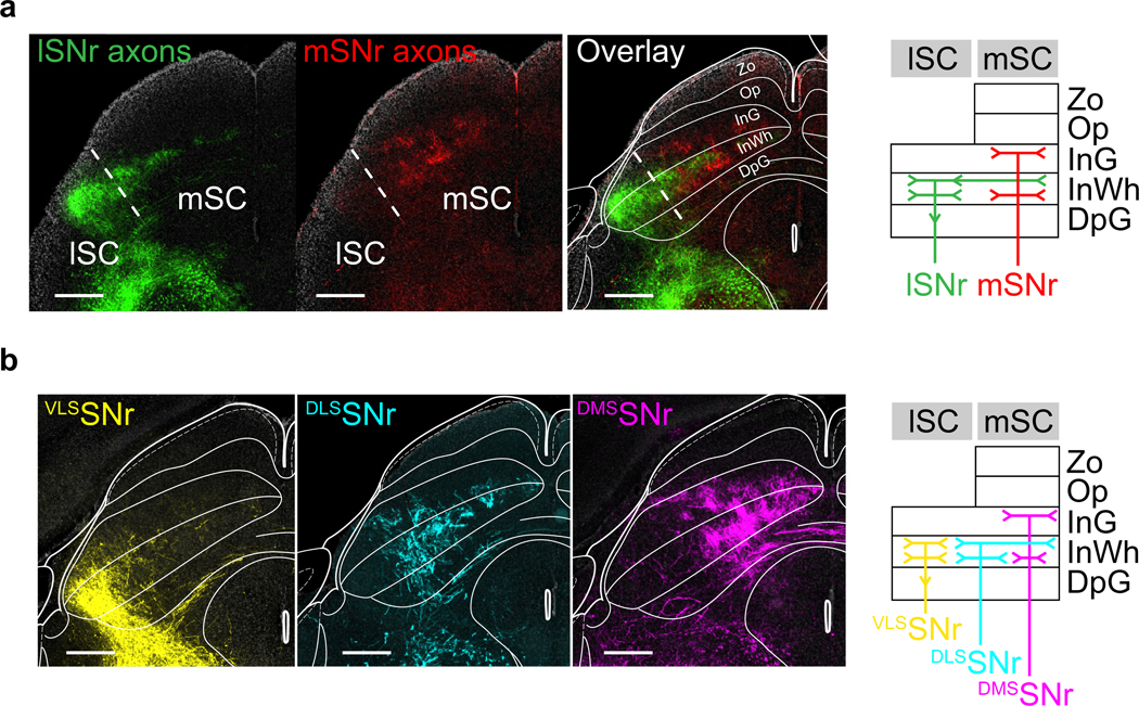
a). left, Example histology section with mSNr axons (red) and lSNr axons (green) from experiment described in Fig 2c. right, Carton diagram summarizing the region and layer specificity of lSNr and mSNr observed. lSNr innervated the lateral SC (abbreviations: Zo: Zona layer of the superior colliculus, Op: optic nerve layer of the superior colliculus, InG: Intermediate gray layer of the superior colliculus, InWh: Intermediate white layer of the superior colliculus, DpG: Deep gray layer of the superior colliculus). lSNr innervated the lSC in InWh, and extending to upper layer of InWh in mSC. mSNr innervated the superfifical part of InG and deeper part of InWh in mSC. Similar results were obtained in n = 4 mice. Scale bar, 500um.
b). left, Example histological section with VLSSNr (yellow), DLSSNr (cyan), and DMSSNr (magenta) axons in SC (images reproduced from Fig. 2f). right, Carton diagram summarizing the region and layer specificity of VLSSNr, DLSSNr, and DMSSNr observed. VLSSNr targeted the InWh part of lSC, DLSSNr targeted the central part of SC, extending to the upper layer of InWh in mSC, and DMSSNr targeted the upper InG and the lower InWh. Thus, lSNr axons seem to be a combination of VLSSNr and DLSSNr. Scale bar, 500um. Similar results were obtained in n = 9 mice, 3 for each site.
Extended Data Fig. 5. SNr output to Zona Incerta is topographically organized.

a). Example coronal section showing mSNr (red:TdTom)and lSNr (green:EYFP) axon fibers in zona incerta, from experiment described in Fig. 2a. Similar results were obtained in n = 4 mice.
b). Example coronal sections showing DMSSNr (magenta:TdTom), DLSSNr (cyan:TdTom) and VLSSNr (yellow:TdTom), axon fibers in zona incerta, from experiment described in Fig. 2e. Similar results were obtained in n = 9 mice, n = 3 for each site.
Extended Data Fig. 6. Brain regions targeted by SNr.

a) Example histology section of brain regions targeted by DMSSNr, DLSSNr, and VLSSNr. Each row represent a brain region, and each column is a different SNr subpopulation labelled from distinct striatal regions (see experiment described in Fig. 2e).
b) top left, Quantification of normalized fluorescence intensity across brain regions for DMSSNr, DLSSNr, and VLSSNr (see Methods). bottom right, Similar quantification of brain stem regions, IRt and PCRt, but normalized only to total fluorescence in brain stem. Abbreviations. VM/VA: ventromedial/ventral anterior thalamus, PC/CL/CM: paracentral/centrolateral/central medial thalamus, Pf: parafascicular nucleus, LH: lateral hypothalamus, IC: inferior colliculus, SC: superior colliculus, ZI: zona incerta, PAG: paracqeuductal gray, MA3: medial accessory oculomotor nucleus, MLR: mesencephalic locomotor region, PnO: pontine reticular nucleus, oral part, LDTg: laterodorsal tegmental nucleus, PB: parabrachical nuecleus, IRt: intermediate reticular nucleus, PCRt: parvicellular reticular nucelus, Gi: gigantocellular reticular nucleus (DMSSNr: n=2 mice; DLSSNr: n=3 mice; VLSSNr: n=3 mice)
Extended Data Fig. 7. Anterogradely labelled putative dopamine axons in striatum.
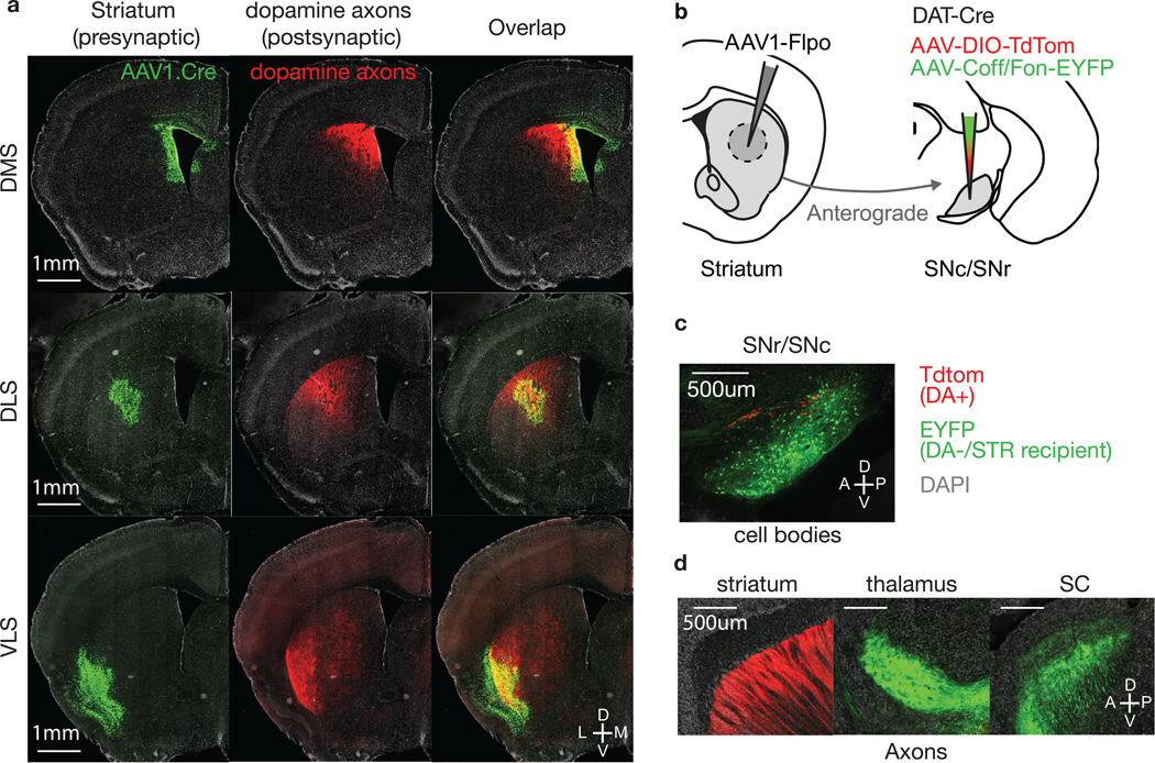
a) Example coronal sections showing putative dopamine axons in striatum (from experiment described in Fig. 2e). Each row represent a distinct striatal injection of AAV1.cre from DMS, DLS and VLS. Injection site is shown in green (H2b-EGFP), dopamine axons in red (TdTom). For all three striatal injections, dopamine axons tend to co-localize with the injection site. Similar results were obtained in n = 9 mice, 3 for each site.
b) Schematic showing experiment for validating the axons observed in striatum are dopamine axons. AAV1-Flpo was injected striatum, followed by a cocktail of AAV-DIO-TdTom and AAV-Coff/Fon-EYFP in SNr/SNc, in a Slc6a3-IRES-Cre mouse, where Cre is expressed in dopamine neurons. This allowed us to anterogradely label SNr neurons, similar to experiment in Fig. 2e, but excluding the dopamine neurons (DA-/STR recipient), while also labelling dopamine neurons as a control.
c) Example sagittal section showing the injection site. Dopamine neurons are expressing TdTom (red) whereas non-dopaminergic/anterogradely labelled cells are expressing EYFP (green). Similar results were obtained in n = 2 mice.
d) Sagittal sections showing axons in striatum (left), thalamus (middle) and SC (right). Dopaminergic axons (red:TdTom) were only seen in striatum, whereas non-dopaminergic/striatal recipient axon (green:EYFP) were only seen in thalamus and SC. Given the lack of EYFP fibers in striatum, axons seen in striatum from anterograde tracing at striatum (experiment in Fig. 2e) likely are dopamine axons. Similar results were obtained in n = 2 mice.
Extended Data Fig. 8. SC projects back to Pf and VM in a topographical fashion.

a). Overlap of SNr axons labelled via anterograde tracing in striatum (AAV1.Cre, see Fig. 2e) and cortical axons. Scale bar, 500um. Allen Institute for Brain Science. Allen Mouse Brain Connectivity Atlas (2011). Available from https://connectivity.brain-map.org/.
b). Experimental protocol for labelling medial and lateral SC. Two anterograde tracers (AAV1.Cre and AAV1.Flpo) were injected in ACA/tjM1 respectively, followed by AAV.DIO.TdTom or AAV.fDIO.EYFP in medial or lateral SC. This allowed labelling mSC and lSC without leaking into other regions outside SC.
c). Example coronal section showing the injection site in SC (mSC in red, lSC in green). Similar results were obtained in n = 3 mice. Scale bar, 1mm.
d). Example coronal sections showing the axonal targets of mSC and lSC. We observed topography in both Pf and VM, similar to SNr topography (see main Text). Similar results were obtained in n = 3 mice. Scale bar, 1mm.
Extended Data Fig. 9. Detailed optical setup for TF stimulation.

The optical setup allows depth dependent optical illumination combined with TF. The main components are: P1: pockel cell (or any power modulator), S1: shutter, M1: piezo mirror, M3: small mirror (0.5” diameter), M2: galvo mirror, L1: Achromatic double (AC508–200-A-ML, f=200mm, diameter 2”, Thorlabs), L2: Aspheric condenser (ACL5040-A, f=40mm, diameter 50mm, Thorlabs), X1: XY translation cage mount + Z-axis translation mount (Thorlabs). M2 galvo mirror was used to change the incident angle onto the patchcord attached at the end of X1. M1 was used to correct for any misalignment for each angle.
Extended Data Fig. 10. dSPNs VLS stimulation engage cortical and collicular BG loops.

a) Schematic showing protocol for recording activity in tjM1 and lSC while stimulating VLS dSPNs. Mice implanted with a single tapered fiber targeting VLS, and injected with AAV-DIO-CoChR in VLS, similar to experiment described in Fig. 6a (see methods). Extracellular recording with silicon probe was done above tjM1 and lSC, on the same side (right hemisphere) as the stimulation side in striatum (n = 2 mice).
b) Mean firing rate during the inter-trial-interval where mice were required to withhold licking, and during which VLS dSPNs stimulation caused contralateral licking (Fig. 6). Mean firing rate of both tjM1 (left) and lSC (right) increased during stim (blue, 100 ms stim) relative to no stim (grey). Shaded light blue represents laser on period (100ms) (n = 102 units in tjM1, n = 65 units in lSC) (mean ± s.e.m across neurons).
c) Fraction cells that were significantly modulated by dSPNs stimulation in VLS in tjM1 (top) and SC (bottom). Cells are categorized into either excited (blue), inhibited (red) or no sigficant change (grey). The majority of cells recorded (53% in tjM1, 68% in lSC) were excited by the stimulation (0–500 ms window relative to laser onset, p<0.05, Mann-Whitney U test, see Methods).
d) Mean firing rate, during tone presentation, of cells that were significantly modulated during ITI stimulation. Firing rate for tjM1 (left) and lSC (right) in left trials and right trials. Firing rate during no stim (grey) and during stim trials (blue). Shaded light blue represents laser on period (100ms) (n=102 units in tjM1, n=65 units in lSC) (mean ± s.e.m across neurons).
Acknowledgments
We thank members of the Sabatini lab, Dr. Regehr, Dr. Andermann, Dr. Uchida for helpful discussions. We thank J. Levasseur for mouse husbandry and genotyping, J. Saulnier and L. Worth for lab administration. We thank W. Kuwamoto, J. Grande, M. Ambrosino, B. Pryor and E. Lubbers for assistance with behavioral experiments and histology. This work was supported by grants from NIH (NINDS R01NS103226), P30 Core Center Grant (NINDS NS072030), Iljou Foundation scholarship, and a grant from the Simons Collaborative on the Global Brain.
Footnotes
Competing Interests Statement
Dr. Sabatini is a founder of and holds private equity in Optogenix. Tapered fibers commercially available from Optogenix were used as tools in the research.
References
- 1.Roseberry TK et al. Cell-Type-Specific Control of Brainstem Locomotor Circuits by Basal Ganglia. Cell 164, 526–537 (2016). [DOI] [PMC free article] [PubMed] [Google Scholar]
- 2.Kravitz AV et al. Regulation of parkinsonian motor behaviours by optogenetic control of basal ganglia circuitry. Nature 466, 622–626 (2010). [DOI] [PMC free article] [PubMed] [Google Scholar]
- 3.Tai L-H, Lee AM, Benavidez N, Bonci A & Wilbrecht L Transient stimulation of distinct subpopulations of striatal neurons mimics changes in action value. Nat. Neurosci. 15, 1281–1289 (2012). [DOI] [PMC free article] [PubMed] [Google Scholar]
- 4.Xiong Q, Znamenskiy P & Zador AM Selective corticostriatal plasticity during acquisition of an auditory discrimination task. Nature 521, 348–351 (2015). [DOI] [PMC free article] [PubMed] [Google Scholar]
- 5.Znamenskiy P & Zador AM Corticostriatal neurons in auditory cortex drive decisions during auditory discrimination. Nature 497, 482–485 (2013). [DOI] [PMC free article] [PubMed] [Google Scholar]
- 6.Reynolds JNJ, Hyland BI & Wickens JR A cellular mechanism of reward-related learning. Nature 413, 67–70 (2001). [DOI] [PubMed] [Google Scholar]
- 7.Shen W, Flajolet M, Greengard P & Surmeier DJ Dichotomous Dopaminergic Control of Striatal Synaptic Plasticity. Science 321, 848–851 (2008). [DOI] [PMC free article] [PubMed] [Google Scholar]
- 8.Alexander GE, DeLong MR & Strick PL Parallel Organization of Functionally Segregated Circuits Linking Basal Ganglia and Cortex. Annu. Rev. Neurosci. 9, 357–381 (1986). [DOI] [PubMed] [Google Scholar]
- 9.Deniau JM & Chevalier G. The lamellar organization of the rat substantia nigra pars reticulata: Distribution of projection neurons. Neuroscience 46, 361–377 (1992). [DOI] [PubMed] [Google Scholar]
- 10.Deniau JM, Menetrey A & Charpier S. The lamellar organization of the rat substantia nigra pars reticulata: Segregated patterns of striatal afferents and relationship to the topography of corticostriatal projections. Neuroscience 73, 761–781 (1996). [DOI] [PubMed] [Google Scholar]
- 11.Kolomiets BP et al. Segregation and Convergence of Information Flow through the Cortico-Subthalamic Pathways. J. Neurosci. 21, 5764–5772 (2001). [DOI] [PMC free article] [PubMed] [Google Scholar]
- 12.Kolomiets BP, Deniau JM, Glowinski J & Thierry AM Basal ganglia and processing of cortical information: functional interactions between trans-striatal and trans-subthalamic circuits in the substantia nigra pars reticulata. Neuroscience 117, 931–938 (2003). [DOI] [PubMed] [Google Scholar]
- 13.Kravitz AV, Tye LD & Kreitzer AC Distinct roles for direct and indirect pathway striatal neurons in reinforcement. Nat. Neurosci. 15, 816–818 (2012). [DOI] [PMC free article] [PubMed] [Google Scholar]
- 14.Yttri EA & Dudman JT Opponent and bidirectional control of movement velocity in the basal ganglia. Nature 533, 402–406 (2016). [DOI] [PMC free article] [PubMed] [Google Scholar]
- 15.Wang L, Rangarajan KV, Gerfen CR & Krauzlis RJ Activation of Striatal Neurons Causes a Perceptual Decision Bias during Visual Change Detection in Mice. Neuron 97, 1369–1381.e5 (2018). [DOI] [PMC free article] [PubMed] [Google Scholar]
- 16.Kelly RM & Strick PL Macro-architecture of basal ganglia loops with the cerebral cortex: use of rabies virus to reveal multisynaptic circuits. in Progress in Brain Research vol. 143 447–459 (Elsevier, 2004). [DOI] [PubMed] [Google Scholar]
- 17.Saunders A et al. A direct GABAergic output from the basal ganglia to frontal cortex. Nature 521, 85–89 (2015). [DOI] [PMC free article] [PubMed] [Google Scholar]
- 18.Jackson A & Crossman AR Subthalamic nucleus efferent projection to the cerebral cortex. Neuroscience 6, 2367–2377 (1981). [DOI] [PubMed] [Google Scholar]
- 19.Aoki S et al. An open cortico-basal ganglia loop allows limbic control over motor output via the nigrothalamic pathway. eLife 8, e49995 (2019). [DOI] [PMC free article] [PubMed] [Google Scholar]
- 20.Sippy T, Lapray D, Crochet S & Petersen CCH Cell-Type-Specific Sensorimotor Processing in Striatal Projection Neurons during Goal-Directed Behavior. Neuron 88, 298–305 (2015). [DOI] [PMC free article] [PubMed] [Google Scholar]
- 21.Babl SS, Rummell BP & Sigurdsson T. The Spatial Extent of Optogenetic Silencing in Transgenic Mice Expressing Channelrhodopsin in Inhibitory Interneurons. Cell Rep. 29, 1381–1395.e4 (2019). [DOI] [PubMed] [Google Scholar]
- 22.Li N et al. Spatiotemporal constraints on optogenetic inactivation in cortical circuits. eLife 8, e48622 (2019). [DOI] [PMC free article] [PubMed] [Google Scholar]
- 23.Travers JB, Dinardo LA & Karimnamazi H. Motor and Premotor Mechanisms of Licking. Neurosci. Biobehav. Rev. 21, 631–647 (1997). [DOI] [PubMed] [Google Scholar]
- 24.Wang S & Redgrave P. Microinjections of muscimol into lateral superior colliculus disrupt orienting and oral movements in the formalin model of pain. Neuroscience 81, 967–988 (1997). [DOI] [PubMed] [Google Scholar]
- 25.Sahibzada N, Dean P & Redgrave P. Movements resembling orientation or avoidance elicited by electrical stimulation of the superior colliculus in rats. J. Neurosci. 6, 723–733 (1986). [DOI] [PMC free article] [PubMed] [Google Scholar]
- 26.Capelli P, Pivetta C, Esposito MS & Arber S. Locomotor speed control circuits in the caudal brainstem. Nature 551, 373–377 (2017). [DOI] [PubMed] [Google Scholar]
- 27.Zingg B et al. AAV-Mediated Anterograde Transsynaptic Tagging: Mapping Corticocollicular Input-Defined Neural Pathways for Defense Behaviors. Neuron 93, 33–47 (2017). [DOI] [PMC free article] [PubMed] [Google Scholar]
- 28.Zingg B, Peng B, Huang J, Tao HW & Zhang LI Synaptic Specificity and Application of Anterograde Transsynaptic AAV for Probing Neural Circuitry. J. Neurosci. 40, 3250–3267 (2020). [DOI] [PMC free article] [PubMed] [Google Scholar]
- 29.Hunnicutt BJ et al. A comprehensive excitatory input map of the striatum reveals novel functional organization. eLife 5, e19103 (2016). [DOI] [PMC free article] [PubMed] [Google Scholar]
- 30.Hintiryan H et al. The mouse cortico-striatal projectome. Nat. Neurosci. 19, 1100–1114 (2016). [DOI] [PMC free article] [PubMed] [Google Scholar]
- 31.Hooks BM et al. Topographic precision in sensory and motor corticostriatal projections varies across cell type and cortical area. Nat. Commun. 9, 1–16 (2018). [DOI] [PMC free article] [PubMed] [Google Scholar]
- 32.Mastro KJ, Bouchard RS, Holt HAK & Gittis AH Transgenic Mouse Lines Subdivide External Segment of the Globus Pallidus (GPe) Neurons and Reveal Distinct GPe Output Pathways. J. Neurosci. 34, 2087–2099 (2014). [DOI] [PMC free article] [PubMed] [Google Scholar]
- 33.Mana S & Chevalier G. The fine organization of nigro-collicular channels with additional observations of their relationships with acetylcholinesterase in the rat. Neuroscience 106, 357–374 (2001). [DOI] [PubMed] [Google Scholar]
- 34.Mandelbaum G et al. Distinct Cortical-Thalamic-Striatal Circuits through the Parafascicular Nucleus. Neuron 102, 636–652.e7 (2019). [DOI] [PMC free article] [PubMed] [Google Scholar]
- 35.Klapoetke NC et al. Independent optical excitation of distinct neural populations. Nat. Methods 11, 338–346 (2014). [DOI] [PMC free article] [PubMed] [Google Scholar]
- 36.Kuramoto E et al. Ventral Medial Nucleus Neurons Send Thalamocortical Afferents More Widely and More Preferentially to Layer 1 than Neurons of the Ventral Anterior-Ventral Lateral Nuclear Complex in the Rat. Cereb. Cortex 25, 221–235 (2015). [DOI] [PubMed] [Google Scholar]
- 37.Rubio-Garrido P, Pérez-de-Manzo F, Porrero C, Galazo MJ & Clasca F. Thalamic Input to Distal Apical Dendrites in Neocortical Layer 1 Is Massive and Highly Convergent. Cereb. Cortex 19, 2380–2395 (2009). [DOI] [PubMed] [Google Scholar]
- 38.Krout KE, Loewy AD, Westby GWM & Redgrave P. Superior colliculus projections to midline and intralaminar thalamic nuclei of the rat. J. Comp. Neurol. 431, 198–516 216 (2001). [DOI] [PubMed] [Google Scholar]
- 39.McHaffie JG, Stanford TR, Stein BE, Coizet V & Redgrave P. Subcortical loops through the basal ganglia. Trends Neurosci. 28, 401–407 (2005). [DOI] [PubMed] [Google Scholar]
- 40.Chevalier G & Deniau JM Spatio-temporal organization of a branched tecto-spinal/tecto-diencephalic neuronal system. Neuroscience 12, 427–439 (1984). [DOI] [PubMed] [Google Scholar]
- 41.Oh SW et al. A mesoscale connectome of the mouse brain. Nature 508, 207–214 (2014). [DOI] [PMC free article] [PubMed] [Google Scholar]
- 42.Rossi MA et al. A GABAergic nigrotectal pathway for coordination of drinking behavior. Nat. Neurosci. 19, 742–748 (2016). [DOI] [PMC free article] [PubMed] [Google Scholar]
- 43.Evans DA et al. A synaptic threshold mechanism for computing escape decisions. Nature 558, 590–594 (2018). [DOI] [PMC free article] [PubMed] [Google Scholar]
- 44.Shang C et al. A parvalbumin-positive excitatory visual pathway to trigger fear responses in mice. Science 348, 1472–1477 (2015). [DOI] [PubMed] [Google Scholar]
- 45.Pisano F et al. Depth-resolved fiber photometry with a single tapered optical fiber implant. Nat. Methods 16, 1185–1192 (2019). [DOI] [PubMed] [Google Scholar]
- 46.Pisanello M et al. Tailoring light delivery for optogenetics by modal demultiplexing in tapered optical fibers. Sci. Rep. 8, 1–11 (2018). [DOI] [PMC free article] [PubMed] [Google Scholar]
- 47.Pisanello F et al. Dynamic illumination of spatially restricted or large brain volumes via a single tapered optical fiber. Nat. Neurosci. 20, 1180–1188 (2017). [DOI] [PMC free article] [PubMed] [Google Scholar]
- 48.Gong S et al. Targeting Cre Recombinase to Specific Neuron Populations with Bacterial Artificial Chromosome Constructs. J. Neurosci. 27, 9817–9823 (2007). [DOI] [PMC free article] [PubMed] [Google Scholar]
- 49.Tecuapetla F, Matias S, Dugue GP, Mainen ZF & Costa RM Balanced activity in basal ganglia projection pathways is critical for contraversive movements. Nat. Commun. 5, 1–10 (2014). [DOI] [PMC free article] [PubMed] [Google Scholar]
- 50.Yin HH & Knowlton BJ The role of the basal ganglia in habit formation. Nat. Rev. Neurosci. 7, 464–476 (2006). [DOI] [PubMed] [Google Scholar]
Additional References
- 51.Guo ZV et al. Flow of Cortical Activity Underlying a Tactile Decision in Mice. Neuron 81, 179–194 (2014). [DOI] [PMC free article] [PubMed] [Google Scholar]
- 52.Cebrián C, Parent A & Prensa L. Patterns of axonal branching of neurons of the substantia nigra pars reticulata and pars lateralis in the rat. J. Comp. Neurol. 492, 349–369 (2005). [DOI] [PubMed] [Google Scholar]
- 53.Oldenburg IA & Sabatini BL Antagonistic but Not Symmetric Regulation of Primary Motor Cortex by Basal Ganglia Direct and Indirect Pathways. Neuron 86, 1174–1181 (2015). [DOI] [PMC free article] [PubMed] [Google Scholar]
Associated Data
This section collects any data citations, data availability statements, or supplementary materials included in this article.
Data Availability Statement
The data that support the findings of this study are available from the corresponding author upon reasonable request. The code used for analysis (Matlab) is also available from the corresponding author upon reasonable request. Detailed information about software and methods used are available online in the Nature Research Reporting Summary.