

Abstract
Tissue-engineered heart valves can be an alternative to prosthetic valves in heart valve replacement; however, they are not fully efficient in terms of long-lasting functionality as leaflets in engineered valves do not possess the native trilayered leaflet structure. Previously, we developed flat, trilayered, oriented nanofibrous (TN) scaffolds mimicking the trilayered structure and orientation of native heart valve leaflets. In-vivo tissue engineering – a practical regenerative medicine technology – can be used to develop autologous heart valves. Thus, in this study, we used our flat, trilayered, oriented nanofibrous scaffolds to develop trilayered tissue structures with native leaflet orientations through in-vivo tissue engineering in a rat model. After two months of in-vivo tissue engineering, infiltrated cells and their deposited collagen fibrils were found aligned in the circumferential and radial layers, and randomly oriented in the random layer of the scaffolds; i.e., trilayered tissue constructs (TTCs) were developed. The tensile properties of the TTCs were higher than that of the control tissue constructs (without any scaffolds) due to the influence of fibers of the scaffolds in tissue engineering. Different extracellular matrix components – collagen, glycosaminoglycans and elastin that exist in native leaflets were observed in the TTCs. Gene expression of the cells in the TTCs indicated that the tissue constructs were in the growing stage. There was no sign of calcification in the tissue constructs. Thus, the TTCs developed with the flat TN scaffolds signify that autologous leaflet-shaped, trilayered tissue constructs that can function as native leaflets can be developed.
Keywords: trilayered, nanofiber, scaffold, cardiac valve leaflet, in-vivo tissue engineering
1. Introduction
For replacement of diseased valves, tissue-engineered heart valves can be an alternative to currently available prosthetic heart valves, the mechanical and bioprosthetic valves, that have inherent limitations (Cebotari, et al., 2006, Gottlieb, et al., 2010, Hoerstrup, et al., 2000, Jana, et al., 2016a). A lifelong anticoagulation medicine is required to prohibit thrombosis caused by mechanical valves (Cannegieter, et al., 1994, Hammermeister, et al., 1993). Degradation and calcification occur in bioprosthetic valves over the passage of time; thus, sequential valve replacements are necessary for the lifetime of a patient (Sacks, et al., 2009, Schoen and Levy, 2005).
However, to date, tissue-engineered heart valves developed in-vitro or in-vivo have not been able to replace damaged or diseased heart valves in patients, possibly due to their functional deficiencies with respect to native heart valves (Bennink, et al., 2018, Hennessy, et al., 2017, Hoerstrup, et al., 2002). Although tissue-engineered valves were mechanically robust and bore physiological pressure, their leaflets did not have the trilayered, oriented structure of native heart valve leaflets comprising a circumferentially oriented fibrosa layer, a randomly oriented spongiosa layer and a radially oriented ventricularis layer (Bennink, Torii, Brugmans, Cox, Svanidze, Ladich, Carrel and Virmani, 2018, Hoerstrup, Kadner, Melnitchouk, Trojan, Eid, Tracy, Sodian, Visjager, Kolb, Grunenfelder, Zund and Turina, 2002, Nakayama, et al., 2015). This trilayered structure in leaflets is important as their residing valvular interstitial cells (VICs) are sensitive to the structure, without which, the VICs may express unwanted myofibroblast phenotype in tissue-engineered leaflets leading to their calcification or shrinkage (Jana and Lerman, 2019, Jana, et al., 2016c, Yip, et al., 2009).
In our previous study, we developed a flat, trilayered, oriented nanofibrous scaffold with circumferentially, randomly and radially oriented layers mimicking the trilayered, oriented structure of a native heart valve leaflet (Jana and Lerman, 2019). Fibrous scaffolds are useful in orienting deposited extracellular matrix as the seeded/infiltrated cells orient themselves along the fibers of the scaffolds (Jana, et al., 2012, Jana, et al., 2016b, Jana and Zhang, 2013). In addition, nanofibers in a fibrous scaffold mimic the morphology of collagen fibrils found in native tissues and thus, the cells can live and grow efficiently in a sufficiently porous nanofibrous scaffold (Flint, et al., 1984). The scaffold was prepared by electrospinning a polycaprolactone (PCL) polymer solution. Any device or scaffold made of PCL polymer does not have any toxicity during its biodegradation and has approval from the FDA for its in-vivo use in a human body (Leung, et al., 2013, Masoumi, et al., 2014). Further, PCL is available in different molecular weights, so mechanical properties and biodegradability of any device made of PCL can be tuned as per requirement (Jana, 2012).
In general, in-vitro tissue engineering focuses on appropriate cell seeding in a scaffold system and then culturing it in a static and/or dynamic environment. However, for neotissue generation, especially of autologous neo-leaflet tissues that need to withstand systemic pressure, in-vivo tissue engineering is more efficient than in-vitro engineering (Nakayama, Takewa, Sumikura, Yamanami, Matsui, Oie, Kishimoto, Arakawa, Ohmuma, Tajikawa, Kanda and Tatsumi, 2015). Our ultimate goal is to develop autologous heart valves through in-vivo tissue engineering that can be directly implanted in patients. Thus, the aim of this study was to perform scaffold-based in-vivo tissue engineering by implanting our previously developed flat, trilayered nanofibrous (TN) scaffolds in a rat model subcutaneously for two months in order to see the effectiveness of the TN scaffolds in producing trilayered tissue constructs (TTCs) with native leaflet orientations. Rat model was chosen because the implant samples fitted into rats subcutaneously and the model was inexpensive and easy to handle. The explanted tissue constructs were characterized physically, mechanically and biologically to find the effect of the TN fibrous structure on infiltrated cells in terms of cell alignment, deposition and alignment of deposited biomolecule fibrils, gene expression of the cells and tensile properties of the constructs. This study aimed to assess the possibility for the future development of in-vivo tissue-engineered, leaflet-shaped, trilayered constructs that can function as a native leaflet.
2. Materials and methods
2.1. Trilayered nanofibrous scaffold development
Procedures to fabricate a TN flat scaffold can be found in detail in our previous study (Jana and Lerman, 2019). In brief, two aluminum rings with an inner diameter of 25 mm and a width of 2 mm were used to develop three collectors in an electrospinning system to fabricate three layers. One ring was used as a collector to fabricate a randomly oriented nanofibrous layer. The same ring with an axial aluminum rod (diameter = 1 mm) extended to its center was used as a collector to fabricate a radially oriented nanofibrous layer. A collector made of equally spaced 12 metal spokes on another ring was used to fabricate a circumferentially oriented nanofibrous layer.
A 10% (wt/v) polycaprolactone (PCL, MW: 80 KD, Sigma Aldrich, USA) solution in trifluoroethanol (Sigma Aldrich, USA) was electrospun to prepare the three above layers. First, a radially oriented nanofibrous layer was prepared on the ring with an axial rod. The axial rod was removed from the ring and electrospinning was performed on the ring containing the radial layer to deposit a randomly oriented layer over the radial layer. This bilayered fibrous structure was then removed from the ring, laid on the ring with 12 spokes and then electrospinning was performed to fabricate a circumferentially oriented layer on the bilayered nanofibrous structure. So, a trilayered nanofibrous scaffold was formed.
2.2. Trilayered nanofibrous (TN) scaffold characterization
TN scaffold samples were processed and imaged with a scanning electron microscope (SEM) (Hitachi, Japan) following a protocol published in our previous paper to perform their physical characterization including morphologies, fiber orientations and fiber diameter (Jana and Lerman, 2019). Fiber diameter was measured from the SEM images (n=5) at different spots (n=10) using a slide caliper (Mitutoyo, Japan) and obtained data were used to find their average and standard deviation. The thickness of the scaffold samples (n=5) at different areas (n=5) were measured by a thickness gauge (Mitutoyo, Japan) and their mean and standard deviation were calculated.
2.3. Mold development and implant preparation
A leaflet-shaped mold was designed and printed in a 3D printer (Stratasys) from a biocompatible polymer - acrylonitrile butadiene styrene (ABS). The mold had three surfaces – the leaflet-surface, the sinus-surface and the base-surface. A TN scaffold was wrapped around the leaflet-surface of the mold and its edge was glued (3M Vetbond tissue adhesive, USA) to the sinus-surface and base-surface of the mold. The circumferential layer of the scaffold was in contact with the leaflet-surface of the mold. A mold-cum-scaffold sample and a bare-mold sample were used as a test sample and a control sample, respectively. A total of 8 test samples and 8 control samples were prepared and sterilized (in ethylene oxide) for their subcutaneous implantation in a rat model.
2.4. Implantation and explantation
Implantation and explantation procedures were performed in accordance with authorization and guidelines of the Ethical Committee of Mayo Clinic, Rochester, MN, USA. Rat (Sprague Dawley, 1–2 months old, ~250 gm weight) model was used for subcutaneous implantation. A total of 4 implant samples – 2 test samples and 2 control samples - were implanted in one rat (Supplementary Fig. S1). Both test and control samples were soaked in blood collected from the tail vein of the same rat in which those blood-soaked samples were implanted. A total of four rats (n=4) were used in this study. Two 3 cm incisions at the dorsal – one above the chest and another below the chest - were made with a sterile scalpel. Then, the skin was loosened from the connective tissue/muscle layer with a blunt dissection to create four subcutaneous pockets of a suitable size at two sides of the incisions to place four implants. Thus, a total of 8 test samples and 8 control samples were implanted in 4 rats. After 2 months of implantation, the samples were carefully explanted. Tissues grown on bare molds were gently collected as control tissue constructs (CTCs). Tissues grown on scaffold-cum-molds were also gently collected as trilayered tissue constructs (TTCs).
2.5. Tensile testing
Tensile tests were performed on TN scaffolds, TTCs and CTCs following a protocol described in detail in our previously published papers (Jana and Lerman, 2019, Jana, et al., 2015). In brief, two window-frames with window dimensions of 5 mm x 4 mm were used to hold a scaffold or tissue sample. A rectangular-shaped scaffold or tissue sample with dimensions of 9 mm x 3 mm was sandwiched between two window-frames and glued (super glue) to prepare a tensile test sample. Tensile tests on TN scaffolds or TTCs were performed in the circumferential direction and on CTCs in any direction. A 500 gm load cell was used to sense the load on samples until their failure. During testing, the samples were pulled at a rate of 0.1 mm/sec and their data (load vs displacement) were recorded. The tissue samples were kept wet by dripping phosphate buffer saline regularly. A total of seven samples (n=7) of each type were used for tensile tests. Modulus and strength (yield stress) were calculated from obtained tensile data following a procedure mentioned in our published papers (Jana and Lerman, 2019, Jana, Lerman and Simari, 2015).
2.6. Transmission electron microscopy imaging
TTC and CTC samples were fixed in 10% formalin and then processed following a protocol described in detail in our previously published papers to embed the samples in epoxy resin (Jana and Lerman, 2019, Jana, Lerman and Simari, 2015). The embedded tissue samples were then sectioned and collected on copper grids. Section samples were then imaged under a transmission electron microscope (TEM) (Jeol, Japan).
2.7. Histological and immunohistochemical Staining
Tissue construct samples (TTCs and CTCs) were fixed in 4% paraformaldehyde and then paraffinized to prepare tissue sections. Tissue sections were then stained histologically with hematoxylin and eosin (Thermo Fisher Scientific, USA), Masson’s trichrome (ScyTek Lab, USA), picrosirius red (ScyTek Lab, USA), Safranin O (ScienCell Research Lab, USA) and alizarin red (Sigma Aldrich, USA) separately. Tissue sections were also stained immunohistochemically with elastin (ab21610, abcam, USA), vimentin (ab92547, abcam, USA), α-smooth muscle actin (SMA) (ab124964, abcam, USA), INOS (ab3523, abcam, USA) and CD206 (orb4941, biorbyt, USA) antibody markers separately. For staining, protocols described in detail in our previously published papers were applied (Jana and Lerman, 2019, Jana, Lerman and Simari, 2015).
2.8. Gene expression
RNAs from tissue construct samples (TTCs and CTCs, n=4 for each) were extracted using a RNeasy mini kit (Qiagen, Germany) and its supplied protocol. RNAs were then purified with DNase I (Life technologies, USA) using manufacture protocol. First-strand cDNAs were then produced from purified RNAs applying a High-Capacity cDNA Reverse Transcription kit with RNase Inhibitor (Applied Biosystems, USA) and its supplied protocol. The TaqMan assay was performed on the produced cDNA transcripts for vimentin (Ss04330801_gH), α-smooth muscle actin (α-SMA, Ss04245588_m1), and type I collagen (COL1A1, Ss03373341_g1) using Lightcycler 480 Probe master mix (Roche, USA). Obtained target gene data were normalized against the ACTB level and analyzed using the comparative cycle threshold (Ct) method. All applied protocols can be found in our previously published papers in detail (Jana and Lerman, 2019, Jana, Lerman and Simari, 2015).
2.9. Collagen, GAG and elastin quantifications
For collagen quantification, the lyophilized tissue construct samples (n=5 for each) were hydrolyzed in 12N HCL at 120°C for 3 hr. The hydrolyzed solution was then treated with a collagen assay kit (Sigma Aldrich, USA) following the manufacturer’s protocol to find the collagen amount in the samples (Jana and Lerman, 2019, Jana, Lerman and Simari, 2015).
For glycosaminoglycan (GAG) quantification, the lyophilized tissue construct samples (n=5 for each) were digested in papain type III (Worthington Biochemical, USA) solution. The digested solution was then treated with a GAG assay kit (Blyscan, Biocolor, USA) following the manufacturer’s protocol to find the GAG amount in the samples (Jana and Lerman, 2019, Jana, Lerman and Simari, 2015).
For elastin quantification, the lyophilized tissue construct samples (n=5 for each) were digested in 0.25M oxalic acid at 100°C for 1 hr. The digested solution was then treated with an elastin assay kit (Blyscan, Biocolor, USA) following the manufacturer’s protocol to find the elastin amount in the samples (Jana and Lerman, 2019, Jana, Lerman and Simari, 2015).
2.10. Quantification using image
Signals in immunostained images (20X) were quantified using MetaMorph software (Molecular Devices Corporation, USA). A threshold color-intensity from all staining images of a particular biomolecule or cell to be quantified was chosen. The percentage of the number of pixels with this threshold intensity (or more) with respect to the total number of pixels of an image was measured. The test sample data (n=10 for each) were normalized against the control sample data (n=10 for each).
2.11. Statistical analysis
Mean ± standard deviation (SD) was used to report the data. An unpaired t-test for two-group comparisons was conducted and P values <0.05 were applied to indicate significance. A one-way ANOVA with Tukey’s post-hoc test for three-group comparisons was conducted and P values <0.05 were applied to indicate significance.
3. Results
3.1. Trilayered nanofibrous scaffold fabrication
For the convenience of the reader, we briefly describe the fabrication method with graphical images; more details can be found in our previous paper (Jana and Lerman, 2019). Two metal rings were prepared to develop trilayered nanofibrous (TN) scaffolds. A radially oriented nanofibrous layer was produced on a collector containing a ring and an axial rod extended to the center of the ring (Fig. 1a and b). A randomly oriented nanofibrous layer was produced on a collector containing a ring only (Fig. 1c and d). A circumferentially oriented nanofibrous layer was produced on a collector containing a ring and 12 metal-spokes (Fig. 1e and f). A 10% PCL solution was used for the electrospinning of nanofibers on the collectors. First, a radially oriented nanofibrous layer was prepared on the ring with an axial rod extended to the center of the ring. The axial rod was removed from the ring and electrospinning was performed to deposit a randomly oriented layer over the radial layer. This bilayered fibrous structure was then laid on the ring with 12 spokes and electrospinning was performed to fabricate a circumferentially oriented layer on the bilayered fibrous structure. Thus, a TN scaffold was fabricated (Figure 1g). Fibers deposited on the metal rings (shown by black arrows, Fig. 1b, d and f) of the collectors made a fibrous ring (shown by a black arrow, Fig. 1g) that provided stability to the scaffold.
Fig. 1.

Fabrication of a TN scaffold. a, b, c Front views of collectors for fabrication of radial, random and circumferential layers. d, e, f Radial, random and circumferential layers fabricated on their corresponding collectors. Fiber deposition on a metal ring pointed by a black arrow. g A fabricated TN scaffold. A fibrous ring is pointed by a black arrow.
A scanning electron microscope was used to analyze the morphologies of three layers in the TN scaffolds. At low magnification, the radial layer showed the presence of radially oriented fibers, the random layer showed the presence of randomly oriented fibers and the circumferential layer showed the presence of circumferentially oriented fibers (Fig. 2a, b and c). Fibers also were deposited on the metal spokes of the circumferential collector to make fibrous spokes that provided stability for the circumferentially oriented fibers. At higher magnification, the orientation of the fibers in each layer was more distinct (shown by arrow sign) (Fig. 2d, e and f). The diameter of the fibers in each layer was around ~ 370 nm.
Fig. 2.

Scanning electron microscopy (SEM) images of different layers of scaffolds. a, b, c SEM images of radial, random and circumferential layers at lower magnification. d, e, f SEM images of radial, random and circumferential layers at higher magnifications. Double headed arrows show the direction of alignment.
3.2. Mold development, implant sample preparation and implantation
A fibrous scaffold was wrapped around a mold to give the scaffold a leaflet shape before implanting it in a rat. The mold was designed and printed in a 3D printer. Fig. 3a shows the leaflet-shaped surface of the mold and Fig. 3b shows the cylindrical-shaped surface (sinus side, marked by a green arrow) and base surface (marked by a red arrow). The radius of curvature of the leaflet-shaped surface was 10 mm, the radius of curvature of the cylindrical-shaped surface was 12.5 mm, the maximum width of the base surface was 12 mm, the length of the base surface was 21 mm and the height of the mold was 11 mm. A TN scaffold was wrapped around the leaflet-shaped surface of the mold and the circumferential layer of the scaffold was in contact with this surface (Fig. 3c). The wrapped sample was then soaked in blood collected from the tail vein of a rat before its subcutaneous implantation in that rat (Fig. 3d). This way, all the test samples were prepared. A total of two test samples (scaffold-wrapped mold) and two control samples (mold only) were implanted in the dorsal area of each rat (Supplementary Fig. S1). A total of 4 rats were used in this study.
Fig. 3.
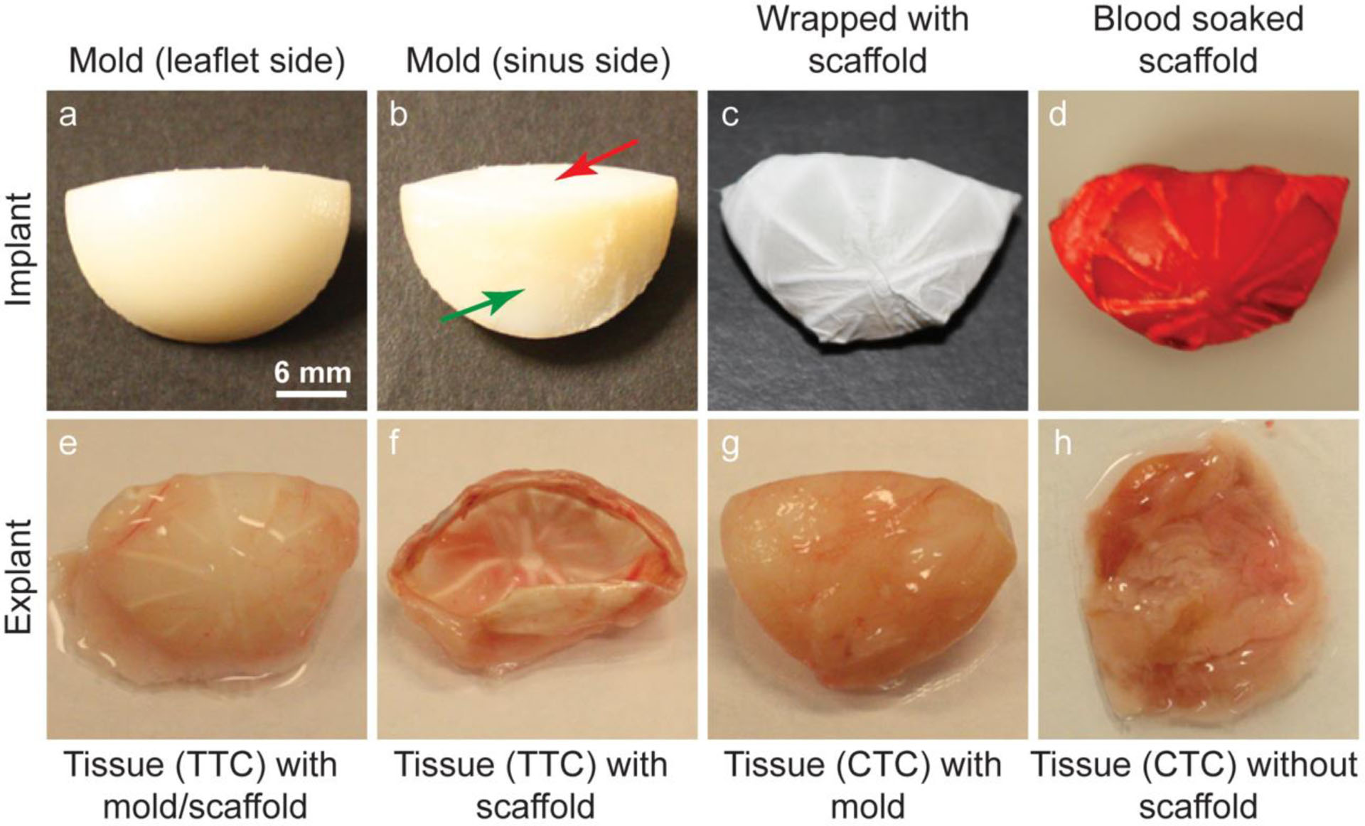
Tissue engineering by implanting scaffolds subcutaneously in a rat model. a, b Different sides of a mold. c A mold wrapped with a TN scaffold. d A blood soaked TN scaffold implanted in a rat model. e An explanted tissue engineered construct with a TN scaffold and a mold. f An explanted tissue engineered construct with a TN scaffold after removal of the mold. g An explanted tissue engineered construct with a mold only. h An explanted tissue engineered construct after removal of the mold
3.3. Explantation and morphology of the tissue constructs
After two months of implantation, the samples (n=8 of each type) were explanted. Fig. 3e shows an explanted test sample (i.e., with scaffold) that still has the molds. After removal of the molds, the explanted TTCs looked like apparent leaflet-shaped tissue constructs with visible nanofibrous spokes (Fig. 3f). Conversely, the CTCs looked like a lump of tissues when the molds were removed from the explanted control samples (i.e., without scaffold) (Fig. 3g and h).
The cross-sectional structures of both CTCs and TTCs were investigated by staining them with hematoxylin and eosin and Masson’s trichrome. The CTCs did not show any particular structure except a lump of tissue (Fig. 4a and b). The presence of collagen was observed in these tissue constructs. Conversely, the TTCs showed a trilayered structure consisting of circumferentially, randomly and radially oriented layers marked by I, II and III, respectively (Fig. 4c and d). The presence of the TN structure in the scaffolds caused the formation of a trilayered structure in the tissue constructs during in-vivo tissue engineering. In the TTCs, the infiltrated cells and their deposited collagen fibrils were aligned (marked by double-headed arrows).
Fig. 4.

Histological staining of tissue construct cross-sections. a Hematoxylin and eosin (H&E) staining of a CTC cross-section. b Masson’s trichrome (MT) staining of a CTC cross-section. c H&E staining of a TTC cross-section. Staining shows the presence of three layers – the circumferential (I), random (II) and radial (III) layers in the construct. A black two-headed arrow shows the direction of alignment of the extracellular matrix in the circumferential layer. d MT staining of a TTC cross-section. Staining shows the presence of three layers – the circumferential (I), random (II) and radial (III) layers in the construct. A black two-headed arrow shows the direction of alignment of the extracellular matrix in the circumferential layer.
Besides staining, the structures of the tissue constructs were examined in a transmission electron microscope to confirm the trilayered structure in the scaffold-based tissue constructs. At lower magnification, three distinct layers – radially, randomly and circumferentially oriented layers marked by I, II and III, respectively, were observed (Fig. 5a). At higher magnification, collagen fibrils (dots as alignment is perpendicular to the paper) were found to be aligned in the radial layer (Fig. 5b), randomly oriented in the random layer (Fig. 5c) and aligned (shown by double-headed arrow) in the circumferentially oriented layer (Fig. 5d). The shapes of the cells indicated their alignments in both radial and circumferential layers. There were no layers in the CTCs (Fig. 5e). At higher magnification, collagen fibrils were found to be randomly oriented in the CTCs (Fig. 5f).
Fig. 5.

Transmission electron microscopy (TEM) images of tissue construct cross-sections. a TEM image of a TTC at lower magnification in which three layers are seen (I, II and III). b TEM image of an aligned radial layer. Orientation of collage fibrils is perpendicular to the paper and so, they are seen as dots. c TEM image of a random layer. d TEM image of an aligned circumferential layer. Orientation of collage fibrils is shown by a two-headed arrow. e TEM image of a CTC at lower magnification and there was only one layer. f TEM image of a CTC at higher magnification and collagen fibrils were randomly oriented.
3.4. Tensile test
Tensile tests were performed on TN scaffolds, TCTs and CTCs to investigate any influence of fibers in the TN scaffolds on tensile properties of the engineered tissues (Fig. 6). For TN scaffolds and TTCs, tensile tests were performed in circumferential direction only because thick nanofibrous spokes existed in the radial direction would interfere in measuring their tensile properties in radial direction. The tensile modulus of the TTCs (3.032 ± 0.873 MPa) was significantly higher than that of both the TN scaffolds (0.641 ± 0.217 MPa) and CTCs (1.753 ± 0.876 MPa). Similarly, the tensile strength (yield stress) of the TTCs (0.679 ± 0.142 MPa) was significantly higher than that of both the TN scaffolds (0.408 ± 0.133 MPa) and CTCs (0.422 ± 0.139 MPa). The tensile results show that the presence of nanofibers influenced the tensile properties of the tissue constructs.
Fig. 6.

Tensile tests (for each n=7) of TN scaffolds, TTCs and CTCs. Tensile modulus of TTCs was significantly higher than that of TN scaffolds and CTCs. Similarly, tensile strength (yield strength) of TTCs was significantly higher than that of TN scaffolds and CTCs.
3.5. Biomolecule quantitation of tissue constructs and their histological and immunostaining
Different components of the extracellular matrix such as collagen, glycosaminoglycans (GAG) and elastin in the tissue constructs were quantified applying appropriate protocols (Fig. 7). The contents of these components in both tissue constructs were compared with that in native heart valve leaflets from pigs. Collagen deposition in CTCs (0.897 ± 0.178 μg/mg) was higher than the collagen content in TTCs (0.848 ± 0.217 μg/mg). Collagen contents in both constructs were lower than that in native leaflets (1.000 ± 0.208 μg/mg). Elastin content in TTCs (0.934 ± 0.255 μg/mg) was higher than that in CTCs (0.820 ± 0.183 μg/mg). Elastin contents in both constructs were lower than that in native leaflets (1.000 ± 0.143 μg/mg). GAG content in TTCs (0.686 ± 0.058 μg/mg) was higher than that in CTCs (0.608 ± 0.168 μg/mg). GAG contents in both constructs were significantly lower than the GAG content in native leaflets (1.000 ± 0.199 μg/mg).
Fig. 7.

Quantification of extracellular matrix components – collagen, glycosaminoglycans (GAG) and elastin in TTCs, CTCs and native heart valve leaflets (for each n=5). Data from TTCs and CTCs were normalized against that of native valve leaflets. GAGs in TTCs and CTCs were significantly less than that in native valve leaflets.
To confirm the above quantification results, the tissue constructs were stained histologically and immunohistochemically (Fig. 8). Collagen staining was performed with picrosirius red and imaged in polarized light. Collagen in CTCs was reddish-yellow in color, whereas that in TTCs was greenish-yellow (Fig. 8a and b). GAG in the construct samples was stained with Safranin O and imaged in plain light. The presence of GAG in TTCs was more than that in CTCs (visually) (Fig. 8c and d). Elastin in the samples was stained immunohistochemically and imaged in plain light. The presence of elastin was observed in both tissue construct samples (Fig. 8e and f).
Fig. 8.

Histological and immunohistochemical staining of CTCs and TTCs. a, b Picrosirius red stained collagen fibrils in CTCs and TTCs. c, d Safranin O stained glycosaminoglycans (GAG) in CTCs and TTCs. e, f Immunohistochemical staining of elastin in CTCs and TTCs.
3.6. Gene expression of infiltrated cells and their immunostaining
Gene expression of cells present in the constructs was assayed to find their phenotype(s). In general, residing valvular interstitial cells in native leaflets show quiescent fibroblast phenotype (vimentin marker); however, they show myofibroblast phenotype (both vimentin and α-SMA (ACTA2) markers) when the leaflets are in a growing, remodeling or diseased state. Thus, vimentin and α-SMA gene expression of cells present in both TTCs and CTCs were assayed. The levels of vimentin and α-SMA gene expression were higher in CTCs than in TTCs (Fig. 9a). In addition to vimentin and α-SMA gene expression, the type I collagen gene (COL1A1) expression of the cells present in both constructs was assayed. Cells in CTCs showed higher COL1A1 expression compared to that in TTCs; although, their difference was not significant (Fig. 9a). Tissue construct samples were immunostained with vimentin and α-SMA protein markers to apparently confirm the above gene expression outcomes. The presence of both protein markers in both types of tissue constructs was observed. Visually, more α-SMA signal was observed in TTCs than in CTCs (Fig. 9b and c) and more vimentin signal was observed in CTCs than in TTCs (Fig. 9d and e). Further, in the TTCs, α-SMA and vimentin signals were more in the circumferential layer than in the other two layers. On the other hand, α-SMA and vimentin signals were observed mostly in blood vessels in CTCs (shown by arrows). Comparatively, TTCs had fewer blood vessels than CTCs (shown by arrows).
Fig. 9.

Gene expression and immunohistochemical staining of cells residing in CTCs and TTCs. a α-SMA (ACTA2), vimentin (VIM) and type-I collagen (COL1A1) gene expression of cells residing in CTCs and TTCs (for each n=4). Data from TTCs were normalized against that of CTCs. b, c Immunohistochemical staining of cells with α-SMA (ACTA2) marker. d, e Immunohistochemical staining of cells with vimentin (VIM) marker. Arrows show the presence of blood vessels in the tissue constructs.
3.7. Calcification assay
For calcification assay of bioprosthetic tissues, rat and rabbit models are routinely used (Wright, et al., 2009). In this study, the rat model was applied in developing tissue constructs subcutaneously and so, during tissue engineering, there was a chance of calcification. Thus, the developed tissue constructs were stained with alizarin red to find any presence of calcific nodules in the tissue constructs (Fig. 10a and b). However, red stain was not seen in the TTCs and CTCs; i.e., no calcification occurred in the developed tissue constructs.
Fig. 10.

Alizarin red staining of CTCs and TTCs. a No red stain i.e. no calcific nodules were found in CTCs. b No red stain i.e. no calcific nodules were found in CTCs either.
3.8. Presence of different cells in the constructs
Besides fibroblast (reason: subcutaneous), the presence of other cells in the implants could be observed after implantation and during subsequent healing and tissue generation (Kenneth Ward, 2008). Thus, the existence of M1 and M2 phenotype macrophages was investigated through their respective antibody-staining method. M1 phenotype macrophages were seen in TCTs and CTCs when constructs were stained with anti-INOS antibody marker (Fig. 11a and b). Similarly, M2 phenotype macrophages were seen in both types of tissue constructs when they were stained with anti-CD206 marker (Fig. 11c and d).
Fig. 11.

Presence of various cells in the tissue constructs was verified using immunohistochemical staining method. a, b Presence of M1 phenotype macrophage cells was investigated by staining with INOS marker. c, d Presence of M2 phenotype macrophage cells was investigated by staining with CD206 marker. e Cell presence was quantified using MetaMorph software on stained images. Data from TTCs (for each n=10) were normalized against that of CTCs (for each n=10). They were significantly different.
To compare the presence of those cells in both TCTs and CTCs quantitatively, their stained images were processed using a software system to obtain their quantitative data (Fig. 11e). The presence of M1 phenotype macrophage cells in CTCs was significantly higher than that in TTCs. Conversely, the presence of M2 phenotype macrophage cells in CTCs was lower than that in TTCs.
4. Discussion
Tissue-engineered valves could be a useful solution to the limitations faced by currently available prosthetic valves (Cebotari, Lichtenberg, Tudorache, Hilfiker, Mertsching, Leyh, Breymann, Kallenbach, Maniuc, Batrinac, Repin, Maliga, Ciubotaru and Haverich, 2006, Gottlieb, Kunal, Emani, Aikawa, Brown, Powell, Nedder, Engelmayr, Melero-Martin, Sacks and Mayer, 2010). However, the structure of tissue-engineered heart valves, especially their tissue-engineered leaflets, should be similar to the trilayered, oriented structure of native valve leaflets in order to provide proper functionalities and longer longevity (Hinton and Yutzey, 2011, Jana and Lerman, 2019, Masoumi, Annabi, Assmann, Larson, Hjortnaes, Alemdar, Kharaziha, Manning, Mayer and Khademhosseini, 2014). Development of TTCs first requires the development of scaffolds with similar trilayered structure so that seeded or infiltrated cells will organize themselves to form trilayered, structured tissues (Cooper, et al., 2010, Kievit, et al., 2013, Neves, et al., 2007). In this context, fibrous scaffolds will be appropriate for tissue engineering as fibers in the scaffolds mimic the morphology of fibrils in the extracellular matrix and can orient the cells as per requirement (Flint, Craig, Reilly, Gillard and Parry, 1984). Applying electrospinning method on collectors, three fibrous layers with fiber orientations mimicking the three orientations of native valve leaflets were prepared (Jana and Lerman, 2019). Applying a special technique, three fibrous layers were made consecutively one over another through a direct deposition procedure to prepare a unified, flat, trilayered and oriented fibrous scaffold.
The development of TTCs could be done through in vitro or in vivo tissue engineering. Our previous work on TTC development through in vitro tissue engineering showed a positive effect of the trilayered, oriented fibrous scaffolds on seeded cells and their deposited collagen fibrils (Jana and Lerman, 2019). However, in-vivo tissue engineering is much efficient than in-vitro tissue engineering for neotissue generation, especially the generation of autologous neo-leaflet tissues that need to withstand systemic pressure (Nakayama, Takewa, Sumikura, Yamanami, Matsui, Oie, Kishimoto, Arakawa, Ohmuma, Tajikawa, Kanda and Tatsumi, 2015). Thus, in this study, we tried to develop TTCs through in-vivo tissue engineering by implanting the trilayered, oriented fibrous scaffolds subcutaneously in a rat model for two months.
The flat TN scaffolds were given an apparent leaflet shape by wrapping them around leaflet-shaped molds; then, the mold-cum-scaffolds were implanted in a rat subcutaneously. After explantation, the obtained tissue constructs held an apparent leaflet shape when the molds were removed from the explants. Deposited extracellular matrix (by the infiltrated cells) and the fibrous scaffold structure enabled the tissue constructs to stay in an apparent leaflet shape after removal of the molds. The trilayered and oriented structure of the constructs was confirmed by staining and TEM images. In other valve tissue engineering methods, cells were constrained to achieve an appropriate aligned structure in engineered tissues; however, the constraints on cells caused retraction of the tissues originated by traction forces that cells employed on the surroundings inside the engineered tissues after the release of applied constraints (Gottlieb, Kunal, Emani, Aikawa, Brown, Powell, Nedder, Engelmayr, Melero-Martin, Sacks and Mayer, 2010, Syedain, et al., 2013a). Conversely, our tissue engineering method applied oriented nanofibers for orientations of the infiltrated cells and their deposited extracellular matrix. Therefore, the infiltrated cells in the TTCs faced almost no constraints, and perhaps no traction force from the infiltrated cells on the engineered tissues. After the removal of the molds, the TTCs did not show any retraction (visually).
The mechanical properties of leaflet tissues should be sufficient to bear the physiological hydrodynamic load after implantation. Previous research studies suggest that tissue-engineered heart valves with a tensile modulus of 3.48 MPa were successfully implanted in a sheep model, although the tensile modulus of sheep heart valve leaflets is ~ 7 MPa (Syedain, Bradee, Kren, Taylor and Tranquillo, 2013a, Syedain, et al., 2013b). Upon valve implantation, the tissue-engineered valves go through a remodeling process through cell infiltration and extracellular matrix deposition leading to improvement of the valve characteristics including mechanical properties (Hennessy, Go, Hennessy, Tefft, Jana, Stoyles, Al-Hijji, Thaden, Pislaru, Simari, Stulak, Young and Lerman, 2017, Syedain, Bradee, Kren, Taylor and Tranquillo, 2013a). The tensile modulus of TTCs developed in this study was ~ 3.03 MPa (close to 3.48 MPa); thus, leaflets made from these TTCs can be used to develop heart valves applicable for valve replacement. The presence of fibers in the TN scaffold influenced tissue engineering, resulting in higher tensile properties in TTCs (~ 3.03 MPa) compared to that in CTCs (~1.75 MPa); thus, it is expected that after implantation, the nanofibers in the constructs would influence in-situ tissue engineering to reach to required native-level characteristics mechanically and biologically (Syedain, Bradee, Kren, Taylor and Tranquillo, 2013a, Syedain, Meier, Reimer and Tranquillo, 2013b).
The presence of extracellular matrix components, especially collagen, glycosaminoglycans and elastin in the tissue-engineered constructs is important as the functionality of the leaflets in native heart valves is associated with the characteristics of those components (Jana and Lerman, 2019, Jana, et al., 2014b, Jana, Tranquillo and Lerman, 2016c). In TTCs, those three extracellular matrix components were present. Collagen and elastin contents in TTCs were not significantly different from that in porcine native leaflets. In CTCs, they were quite similar to that in TTCs and it implies that the fibrous scaffold structure did not inhibit the cells from their infiltration, growth and deposition of the extracellular matrix due to sufficient pore size and pore interconnectivity in the scaffolds (Kolewe, et al., 2013). Fibrous morphology might have provided a favorable environment for sufficient collagen and elastin production in the tissue constructs (Masoumi, Annabi, Assmann, Larson, Hjortnaes, Alemdar, Kharaziha, Manning, Mayer and Khademhosseini, 2014). The glycosaminoglycans contents in the constructs wereless compared to that in native leaflets. However, considering the results from previous studies, the contents of extracellular matrix components in the TTCs were substantial for tissue-engineered heart valve development (Masoumi, Annabi, Assmann, Larson, Hjortnaes, Alemdar, Kharaziha, Manning, Mayer and Khademhosseini, 2014, Masoumi, et al., 2013).
In TTCs, higher amounts of glycosaminoglycans and elastin were present in the circumferential layer than in other layers. In the CTCs, a higher amount of glycosaminoglycans was observed in the blood vessels than in other regions. The presence of collagen in both TTCs and CTCs was quite uniform throughout the constructs. Collagen in CTCs was reddish-yellow in color, whereas that in TTCs was greenish-yellow. There are several opinions regarding the color of collagen fibrils when observed through polarized light (Patel, et al., 2018). According to one opinion, collagen fibrils in CTCs were more mature compared to that in TTCs. Certainly, nanofibers in the scaffolds were responsible for all these observations. Although, all three extracellular matrix components were observed, they were not layer-specific as seen in native leaflets. Thus, orientations and morphologies of fibers in TN scaffolds could not influence the tissue engineering process to achieve layer-specific extracellular matrix deposition. A physiological flow-based dynamic environment may be required to achieve it (Combs and Yutzey, 2009).
Gene expression of cells provides information about the inclination of the cells to produce specific proteins (Jana, et al., 2014a, Jana, Tranquillo and Lerman, 2016c). Smooth muscle cell actin (α-SMA), vimentin and type-I collagen (COL1A1) expression in the cells in CTCs were not significantly higher than that in the cells in TTCs. High α-SMA expression in residing cells in native heart valve leaflets denotes their growing/remodeling/diseased state (Cheung, et al., 2015). However, very high α-SMA expression may cause the formation of fibrous collagen fibrils that decrease the elasticity of engineered tissues, i.e., their functional efficiency (Cheung, Duan and Butcher, 2015). It is possible that the growth rate in CTCs was higher than that in TTCs. The presence of fibers in TN scaffolds might have provided some barrier physically to the infiltrating cells and their growth. Conversely, cells infiltrated into the surrounding regions of bare molds without any restriction, and that is why the growth of the CTCs was a bit higher than that of the TTCs.
Staining images of CTCs with α-SMA and vimentin antibody markers showed a higher presence of α-SMA and vimentin signals in the blood vessel region compared to other regions in the constructs. It is possible that α-SMA and vimentin gene expression of the residing cells in the CTCs were higher than that in the TTCs due to the existence of a large number of blood vessels in CTCs. In the TTCs, α-SMA and vimentin signals were more rampant in the circumferential layer with respect to other layers, although fibers were aligned in both circumferential and radial layers. Lower tensile properties of the circumferential layer compared to that of the radial layer could be responsible for this difference (Jana and Lerman, 2019).
Calcification is one of the major problems that cause diseases in different parts of the cardiovascular system including cardiac valves and blood vessels (Khosla and Eghbali-Fatourechi, 2006, Rajamannan, et al., 2005). To verify that any bioprosthetic tissues (usually fixed/treated) applied as cardiovascular implants don’t calcify, they are placed subcutaneously or intramuscularly in a rat or rabbit model (Wright, Faught and Olin, 2009). In this study, trilayered scaffolds were implanted subcutaneously in a rat model for tissue engineering of trilayered constructs — thus the possibility of calcification in the tissue-engineered constructs. However, alizarin red staining assay of both types of tissue constructs – TTCs and CTCs – demonstrated that no calcification occurred in the tissue constructs. In the tissue constructs, there were no fixing or treating materials that are generally applied during the processing of bioprosthetic tissue (Wright, Faught and Olin, 2009). Further, there is not any research report on calcification caused by any untreated PCL. Thus, the TTCs have a good chance to avoid calcification after their in situ implantation.
The presence of other important cells, mainly M1 and M2 phenotype macrophage cells, was investigated to find whether the fibers in the TN scaffolds influenced their presence. Stained images of TCTs and CTCs showed the presence of these two types of cells in both constructs. However, their quantification data indicated that fibers in the scaffolds influenced positively for higher tissue growth (higher CD206 signal) in the constructs. Higher M1 phenotype signal in CTCs indicated that the solid surface morphology of the molds caused more inflammation compared to the fibrous morphology of the TN scaffolds (Mills, 2012).
Although the developed tissue constructs had a trilayered structure, they could not be used as leaflets for real application because of several limitations including the flat shape of the scaffolds, presence of spokes in the constructs and lower mechanical properties of the constructs (compared to native leaflets). However, these limitations can be solved through the appropriate designing of the scaffolds. Further, considering the positive outcomes including oriented extracellular matrix and cells, and the trilayered structure in the tissue constructs, it is possible to develop autologous native leaflet-shaped trilayered tissue constructs that can be used to generate heart valves for real heart valve transplantation. This is our future goal.
5. Conclusion
By applying the electrospinning method, we prepared trilayered, oriented fibrous scaffolds mimicking the orientations in three layers of native heart valve leaflets. The scaffolds were implanted subcutaneously in a rat model to find the effect of trilayered, oriented fibrous structure on the development of in-vivo generated trilayered tissue constructs. After two months of in-vivo tissue engineering, the developed tissue constructs had a trilayered, oriented structure mimicking the orientations in three layers of native heart valve leaflets. The presence of fibers in the scaffolds increased the tensile properties of the engineered tissue constructs. Amounts of extracellular matrix components – collagen and glycosaminoglycans – in the tissue constructs were not significantly different from that in native leaflets. Vimentin and α-SMA expression of the infiltrated cells in the trilayered constructs indicated that fibers in the scaffolds moderately controlled the tissue growth. There was no sign of calcification in the tissue constructs. The presence of positive cells required for leaflet tissue development was observed in the trilayered constructs.
Supplementary Material
Acknowledgment:
Authors recognize technical assistance of Dr. Federico Franchi.
Funding: This work is supported by the HH Sheikh Hamed bin Zayed Al Nahyan Program in Biological Valve Engineering and the National Institute of Health (NIH #K99HL134823, # R00HL134823).
Footnotes
Publisher's Disclaimer: This Author Accepted Manuscript is a PDF file of a an unedited peer-reviewed manuscript that has been accepted for publication but has not been copyedited or corrected. The official version of record that is published in the journal is kept up to date and so may therefore differ from this version.
Conflict of Interest: There is no conflict of interest.
Ethical Approval: Implantation and explantation procedures were performed in accordance with authorization and guidelines of the Ethical Committee of Mayo Clinic, Rochester, MN, USA.
References
- Bennink G, Torii S, Brugmans M, Cox M, Svanidze O, Ladich E, Carrel T, Virmani R (2018) A novel restorative pulmonary valved conduit in a chronic sheep model: Mid-term hemodynamic function and histologic assessment. J Thorac Cardiovasc Surg 155:2591–2601.e2593 [DOI] [PubMed] [Google Scholar]
- Cannegieter SC, Rosendaal FR, Briet E (1994) Thromboembolic and bleeding complications in patients with mechanical heart valve prostheses. Circulation 89:635–641 [DOI] [PubMed] [Google Scholar]
- Cebotari S, Lichtenberg A, Tudorache I, Hilfiker A, Mertsching H, Leyh R, Breymann T, Kallenbach K, Maniuc L, Batrinac A, Repin O, Maliga O, Ciubotaru A, Haverich A (2006) Clinical application of tissue engineered human heart valves using autologous progenitor cells. Circulation 114:I132–I137 [DOI] [PubMed] [Google Scholar]
- Cheung DY, Duan B, Butcher JT (2015) Current progress in tissue engineering of heart valves: multiscale problems, multiscale solutions. Expert Opin Biol Ther 15:1155–1172 [DOI] [PMC free article] [PubMed] [Google Scholar]
- Combs MD, Yutzey KE (2009) Heart Valve Development Regulatory Networks in Development and Disease. Circulation Research 105:408–421 [DOI] [PMC free article] [PubMed] [Google Scholar]
- Cooper A, Jana S, Bhattarai N, Zhang M (2010) Aligned chitosan-based nanofibers for enhanced myogenesis. J Mater Chem 20:8904–8911 [Google Scholar]
- Flint MH, Craig AS, Reilly HC, Gillard GC, Parry DA (1984) Collagen fibril diameters and glycosaminoglycan content of skins--indices of tissue maturity and function. Connective tissue research 13:69–81 [DOI] [PubMed] [Google Scholar]
- Gottlieb D, Kunal T, Emani S, Aikawa E, Brown DW, Powell AJ, Nedder A, Engelmayr GC, Melero-Martin JM, Sacks MS, Mayer JE (2010) In vivo monitoring of function of autologous engineered pulmonary valve. J Thorac Cardiovasc Surg 139:723–731 [DOI] [PubMed] [Google Scholar]
- Hammermeister KE, Sethi GK, Henderson WG, Oprian C, Kim T, Rahimtoola S (1993) A comparison of outcomes in men 11 years after heart-valve replacement with a mechanical valve or bioprosthesis. Veterans Affairs Cooperative Study on Valvular Heart Disease. N Engl J Med 328:1289–1296 [DOI] [PubMed] [Google Scholar]
- Hennessy RS, Go JL, Hennessy RR, Tefft BJ, Jana S, Stoyles NJ, Al-Hijji MA, Thaden JJ, Pislaru SV, Simari RD, Stulak JM, Young MD, Lerman AA-Ohoo(2017) Recellularization of a novel off-the-shelf valve following xenogenic implantation into the right ventricular outflow tract. Plos One 12: [DOI] [PMC free article] [PubMed] [Google Scholar]
- Hinton RB, Yutzey KE (2011) Heart valve structure and function in development and disease. Annual review of physiology 73:29–46 [DOI] [PMC free article] [PubMed] [Google Scholar]
- Hoerstrup SP, Kadner A, Melnitchouk S, Trojan A, Eid K, Tracy J, Sodian R, Visjager JF, Kolb SA, Grunenfelder J, Zund G, Turina MI (2002) Tissue engineering of functional trileaflet heart valves from human marrow stromal cells. Circulation 106:I143–I150 [PubMed] [Google Scholar]
- Hoerstrup SP, Sodian R, Daebritz S, Wang J, Bacha EA, Martin DP, Moran AM, Guleserian KJ, Sperling JS, Kaushal S, Vacanti JP, Schoen FJ, Mayer JE (2000) Functional living trileaflet heart valves grown in vitro. Circulation 102:44–49 [DOI] [PubMed] [Google Scholar]
- Jana S (2012) Designing of Chitosan-Based Scaffolds for Biomedical Applications Materials Science and Engineering, vol PhD. University of Washington, Seattle, WA, pp 1–136 [Google Scholar]
- Jana S, Cooper A, Ohuchi F, Zhang MQ (2012) Uniaxially Aligned Nanofibrous Cylinders by Electrospinning. ACS Appl Mater Interfaces 4:4817–4824 [DOI] [PubMed] [Google Scholar]
- Jana S, Hennessy R, Franchi F, Young M, Hennessy R, Lerman A (2016a) Regeneration ability of valvular interstitial cells from diseased heart valve leaflets. RSC Advances 6:113859–113870 [Google Scholar]
- Jana S, Lerman A (2019) Behavior of valvular interstitial cells on trilayered nanofibrous substrate mimicking morphologies of heart valve leaflet. Acta Biomater 85:142–156 [DOI] [PMC free article] [PubMed] [Google Scholar]
- Jana S, Lerman A, Simari RD (2015) In Vitro Model of a Fibrosa Layer of a Heart Valve. ACS Appl Mater Interfaces 7:20012–20020 [DOI] [PubMed] [Google Scholar]
- Jana S, Levengood SKL, Zhang M (2016b) Anisotropic Materials for Skeletal-Muscle-Tissue Engineering. Advanced materials (Deerfield Beach, Fla) 28:10588–10612 [DOI] [PMC free article] [PubMed] [Google Scholar]
- Jana S, Simari RD, Spoon DB, Lerman A (2014a) Drug delivery in aortic valve tissue engineering. J Control Release 196:307–323 [DOI] [PubMed] [Google Scholar]
- Jana S, Tefft BJ, Spoon DB, Simari RD (2014b) Scaffolds for tissue engineering of cardiac valves. Acta Biomater 10:2877–2893 [DOI] [PubMed] [Google Scholar]
- Jana S, Tranquillo RT, Lerman A (2016c) Cells for tissue engineering of cardiac valves. J Tissue Eng Regen Med 10:804–824 [DOI] [PubMed] [Google Scholar]
- Jana S, Zhang M (2013) Fabrication of 3D aligned nanofibrous tubes by direct electrospinning. J Mater Chem B 1:2575–2581 [DOI] [PubMed] [Google Scholar]
- Kenneth Ward W (2008) A review of the foreign-body response to subcutaneously-implanted devices: the role of macrophages and cytokines in biofouling and fibrosis. Journal of diabetes science and technology 2:768–777 [DOI] [PMC free article] [PubMed] [Google Scholar]
- Khosla S, Eghbali-Fatourechi GZ (2006) Circulating cells with osteogenic potential In: Zaidi M (ed) Skeletal Development and Remodeling in Health, Disease, and Aging, vol 1068. Annals of the New York Academy of Sciences, pp 489–497 [DOI] [PubMed] [Google Scholar]
- Kievit FM, Cooper A, Jana S, Leung MC, Wang K, Edmondson D, Wood D, Lee JS, Ellenbogen RG, Zhang M (2013) Aligned chitosan-polycaprolactone polyblend nanofibers promote the migration of glioblastoma cells. Advanced Healthcare Materials 2:1651–1659 [DOI] [PMC free article] [PubMed] [Google Scholar]
- Kolewe ME, Park H, Gray C, Ye X, Langer R, Freed LE (2013) 3D structural patterns in scalable, elastomeric scaffolds guide engineered tissue architecture. Advanced materials (Deerfield Beach, Fla) 25:4459–4465 [DOI] [PMC free article] [PubMed] [Google Scholar]
- Leung M, Jana S, Tsao C-T, Zhang M (2013) Tenogenic differentiation of human bone marrow stem cells via a combinatory effect of aligned chitosan–poly-caprolactone nanofibers and TGF-β3. J Mater Chem B 1:6516–6524 [DOI] [PubMed] [Google Scholar]
- Masoumi N, Annabi N, Assmann A, Larson BL, Hjortnaes J, Alemdar N, Kharaziha M, Manning KB, Mayer JE Jr., Khademhosseini A (2014) Tri-layered elastomeric scaffolds for engineering heart valve leaflets. Biomaterials 35:7774–7785 [DOI] [PMC free article] [PubMed] [Google Scholar]
- Masoumi N, Jean A, Zugates JT, Johnson KL, Engelmayr GC Jr. (2013) Laser microfabricated poly(glycerol sebacate) scaffolds for heart valve tissue engineering. J Biomed Mater Res A 101:104–114 [DOI] [PMC free article] [PubMed] [Google Scholar]
- Mills CD (2012) M1 and M2 Macrophages: Oracles of Health and Disease. Critical reviews in immunology 32:463–488 [DOI] [PubMed] [Google Scholar]
- Nakayama Y, Takewa Y, Sumikura H, Yamanami M, Matsui Y, Oie T, Kishimoto Y, Arakawa M, Ohmuma K, Tajikawa T, Kanda K, Tatsumi E (2015) In-body tissue-engineered aortic valve (Biovalve type VII) architecture based on 3D printer molding. J Biomed Mater Res B Appl Biomater 103:1–11 [DOI] [PubMed] [Google Scholar]
- Neves NM, Campos R, Pedro A, Cunha J, Macedo F, Reis RL (2007) Patterning of polymer nanofiber meshes by electrospinning for biomedical applications. International Journal of Nanomedicine 2:433–438 [PMC free article] [PubMed] [Google Scholar]
- Patel B, Xu Z, Pinnock CB, Kabbani LS, Lam MT (2018) Self-assembled Collagen-Fibrin Hydrogel Reinforces Tissue Engineered Adventitia Vessels Seeded with Human Fibroblasts. Scientific reports 8:3294–3294 [DOI] [PMC free article] [PubMed] [Google Scholar]
- Rajamannan NM, Nealis TB, Subramaniam M, Pandya S, Stock SR, Ignatiev CI, Sebo TJ, Rosengart TK, Edwards WD, McCarthy PM, Bonow RO, Spelsberg TC (2005) Calcified rheumatic valve neoangiogenesis is associated with vascular endothelial growth factor expression and osteoblast-like bone formation. Circulation 111:3296–3301 [DOI] [PMC free article] [PubMed] [Google Scholar]
- Sacks MS, Schoen FJ, Mayer JE (2009) Bioengineering challenges for heart valve tissue engineering. Annual review of biomedical engineering 11:289–313 [DOI] [PubMed] [Google Scholar]
- Schoen FJ, Levy RJ (2005) Calcification of Tissue Heart Valve Substitutes: Progress Toward Understanding and Prevention. The Annals of Thoracic Surgery 79:1072–1080 [DOI] [PubMed] [Google Scholar]
- Syedain ZH, Bradee AR, Kren S, Taylor DA, Tranquillo RT (2013a) Decellularized tissue-engineered heart valve leaflets with recellularization potential. Tissue Eng Part A 19:759–769 [DOI] [PMC free article] [PubMed] [Google Scholar]
- Syedain ZH, Meier LA, Reimer JM, Tranquillo RT (2013b) Tubular heart valves from decellularized engineered tissue. Ann Biomed Eng 41:2645–2654 [DOI] [PMC free article] [PubMed] [Google Scholar]
- Wright GA, Faught JM, Olin JM (2009) Assessing anticalcification treatments in bioprosthetic tissue by using the New Zealand rabbit intramuscular model. Comp Med 59:266–271 [PMC free article] [PubMed] [Google Scholar]
- Yip CY, Chen JH, Zhao R, Simmons CA (2009) Calcification by valve interstitial cells is regulated by the stiffness of the extracellular matrix. Arterioscler Thromb Vasc Biol 29:936–942 [DOI] [PubMed] [Google Scholar]
Associated Data
This section collects any data citations, data availability statements, or supplementary materials included in this article.