Abstract
In this study, we present a temporal interference (TI) concept to achieve focal and steerable stimulation in the targeted brain area through transcranial magnetic stimulation (TMS). This method works by inducing two high-frequency electric fields with a slight frequency difference via two independent coils. The intrinsic nonlinear nature of the nerve membrane, which acts as a low-pass filter, does not allow the nerve to engage at high frequencies. Instead, neurons at the intersection of two electric fields can follow the frequency difference of the two fields. For 3D MRI-derived head models, the finite element method is used to compute the electric field induced by the time-varying magnetic field along with the electric field penetration depth and the activated volume for the specific coil parameters. A deeper stimulation with an acceptable spatial spread can be obtained by controlling the intersection of the fields by finding the optimal position and orientation of the two coils. Moreover, by changing the voltage ratio of the coils, and not their mechanical orientation, the intended area can be dynamically driven. The computational results show that the TI technique is an efficient approach to resolve the electric field depth-focality trade-off, which can be a reasonable alternative to complex coil designs. The system proposed in this paper shows a great promise for a more dynamic and focused magnetic stimulation.
Index Terms: Transcranial magnetic stimulation, Temporal interference, TMS focality, deep TMS, TI-TMS, TMS coil design
I. Introduction
The potential to influence brain activity and modulate physiological and behavioral performance through a noninvasive intervention has led to the rapid development of transcranial magnetic stimulation (TMS) and electric stimulation (TES) techniques. In these methods, current and magnetic stimuli play a key role in the action on brain functions. The depth of the electric field (E-field) penetration and the accuracy of the spatial targeting (called focality) are two significant performance parameters in the design of transcranial stimulation systems. In treatments where the targeted region is small, it is preferred to concentrate the induced E-field on the intended area and minimize the stimulation in the non-targeted regions because wide stimulation of the brain can influence the obtained clinical results. Extensive brain stimulation can also cause accidental epileptic seizures and other side effects [1].
There is also considerable interest in stimulating deep areas of the brain via noninvasive techniques. However, these are not effortlessly accessible without widespread stimulation due to the depth-focality trade-off of the induced field, which is governed by the principles of qualitative physics and Maxwell’s equations [2]. By comparing 50 TMS coil designs, Deng et al. concluded that stimulating the deep areas of the brain would cause a wide E-field spread [1]. However, some of the recognized properties of nerve tissue lead researchers to find different solutions to this trade-off. One example is the intrinsic nonlinear low-pass filtering property of the nerve membrane, which may prevent neurons from directly following very high-frequency sinusoidal fields [3]. In the animal model, Grossman et al. observed that by injecting two identical high-frequency (called carrier) electric currents into two pairs of electrodes, neurons could not follow them. But when the two frequencies are slightly different, where the stimuli overlap, the nerves are able to track the frequency difference (called envelope or beat frequency). This phenomenon is titled temporal interference (TI) [4]. Using finite element simulations, Cao et al. suggested that by increasing the number of electrode pairs, better spatial accuracy could be obtained [5]. Additionally, they demonstrated that by changing the magnitude of the currents injected into the pair of electrodes while keeping the sum of the currents constant, TI could steer the stimulation location.
However, in those systems, which are based on TES’s technique, the density of the injected current and the electric field (magnitude, shape and direction) fluctuate with the impedance and the tissue anatomy (especially the head size and the thickness of the skull). In the voltage-controlled TES systems, the injected current into the tissue and thus the current density and the magnitude of the electric field will depend on the impedance between the electrodes. In these systems, the skin-electrode impedance variations play a crucial role. Conversely, in current-controlled systems, the density of the injected current and the E-field magnitude can be kept constant, but the injected voltage waveform must be changed, and the electric field waveform would be different from the predetermined shape [6]. As a result of these limitations, TI’s implementation with the TES method, which requires the accurate current density and the waveform of the E-field, substantially reduces the spatial precision.
On the other hand, the magnetic field generated by the TMS system is not affected by the presence/absence of biological tissue around it. A major distortion of the magnetic field does not occur due to the high impedance of the head tissues [6]. The stimulus waveform (and consequently the induced electric field waveform) and the amplitude of stimulus in the coil (and consequently the magnitude of the induced electric field) are independent of the nervous tissue and will be almost constant. Hence, it can be predicted that the use of the magnetic stimulation technique may be more effective at implementing the TI method. In this study, the concept of TI for TMS with different coil orientations is designed and evaluated with a numerical technique for the first time. This paper should offer beneficial insights into the depth and the spatial targeting of the induced E-field in TMS systems.
II. Methods
A. Head model and solver
In this research, the three-dimensional MRI-derived head model is utilized. The head tissue is assumed to be homogeneous with an electrical conductivity of 33 S/m [7]. The dimensions and the specifications of the coils are derived from [1]. The finite element method (FEM) is used to find the induced E-field and the penetration depth. For this purpose, COMSOL Multi-physics 5.3 software is selected with a linear solver. Given that the model chosen for the head is linear for all frequencies, the results obtained in COMSOL are transferred to MATLAB and demodulated to derive the TI property.
B. Proposed design
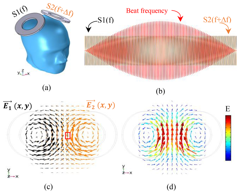
The overall design framework of the proposed temporally interfering TMS (TI-TMS) is shown in Fig. 1. Two coils with a determined distance and angle are placed on the skull. Two high-frequency magnetic stimuli (S1 and S2) are injected with a low-frequency difference (Δf), as shown in Fig. 1 (a-b). At the intersection of these two stimuli, the electric field interference occurs and the E-field vectors add together, as displayed in Fig. 1 (c-d). In areas of the brain where no interference has taken place, the nerves do not fire because of the high frequency of the stimuli compared to the slow response of the nerve membranes. But in places where the interference has occurred, the neurons can be engaged by the slow beat frequency, which is equal to the frequency difference of the two stimuli.
Figure 1.
Concept of the proposed TI-TMS system; (a) Placing two independent stimulation coils on the skull. The stimulus injected into one coil has a frequency of (f) Hz and another has a frequency of (f+ Δf) Hz. (b) The shape of the waves of the injected stimuli (S1 and S2) and their envelope (beat frequency) as a temporal interference effect. (c) E-field vectors caused by S1 and S2 (without interference). An example of where the E-field interference occurs is shown in the red box. (d) The sum of electric field vectors resulting from the interference. (c) and (d) are obtained at the moment when the interference vectors of the two electric fields are at their maximum.
The expected effect of TI-TMS on the neurons can be explained by considering the Hodgkin-Huxley model which describes the current flow along a nerve fibre. It can be summarised as
| (1) |
where V is the membrane voltage, Cm is the membrane capacitance, gi and Ei respectively are the conductances and reversal potentials of ions, α is the radius of the fibre and R is the specific resistance of the axoplasm [8]. The equation consists of two linear terms, and Σi gi(V − Ei) which describes the current flowing through the ion channels of the membrane. This introduces a nonlinearity since the conductances gi depend on the membrane voltage. If the nervous system was considered a linear system, two inputs at different frequencies would be expected to give an output at the same two frequencies. For the case of TI this would mean the neural response would be at the same frequencies as the stimuli. However, due to the nonlinearity of the neuronal membrane, the output includes intermodulation products at frequencies that are the difference and the sum of the input frequencies [9]. For temporal interference, the frequency difference (Δf) will be small compared to the high frequencies of the stimuli and of the other intermodulation products. Since the neurons will not be able to follow the high-frequency stimuli, the input frequencies as well as high-frequency intermodulation products will be filtered out and the neurons are expected to be only activated at the frequency difference (Δf) of the stimuli.
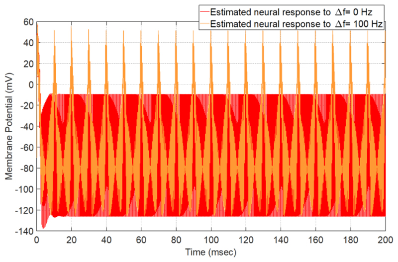
To estimate the effect of TI on neural tissue, we solve (1) with Euler’s numerical solution method (∂t = 1usec). The number of iterations is 20000 and the equation’s constant parameters are selected from [10]. The results of this estimation are shown in Fig. 2. When the high frequency stimuli do not have a frequency difference (Δf = 0 Hz), the voltage changes of the membrane will be less than the threshold value of its excitation and the neuron does not reveal any tendency of activation. But for a frequency difference of 100 Hz (Δf = 100 Hz), the neuron can fire.
Figure 2.
Utilizing the Hodgkin-Huxley model to estimate the neural response for two high frequency magnetic pulses with Δf = 0 Hz and Δf = 100 Hz. For Δf = 100 Hz, the interval between the two stimuli is equal to 10 ms (1/Δf)
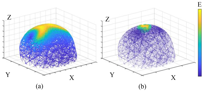
The impact of using the proposed TI-TMS method for spatial targeting is displayed in Fig. 3. For the orientation of the coils shown in Fig. 1 (a), if two low-frequency stimuli are injected (so that neurons can directly follow them), the result of Fig. 3 (a) will be achieved. Clearly, a wide area of the brain will be engaged. But if the stimuli frequencies are higher than the frequency response of the neuronal membrane and have a small frequency difference (according to the TI method), more focal stimulation will occur at the intersection of the two E-fields. The coils used in this structure are Magstim 90 mm single circular coils (P/N 3192).
Figure 3.
Electric field interference and focus capability - (a) The brain is stimulated by two identical low-frequency stimuli, which results in a broad stimulated region. (b) The brain is stimulated by two different high-frequency stimuli (here at frequencies of 10 kHz and 10.04 kHz). It can be seen that the activated area is confined to the interference locus of the two E-fields. (a) and (b) are obtained at the moment when the interference vectors of the two electric fields are at the maximum magnitude. All axes are written in meters.
III. Results and Discussion
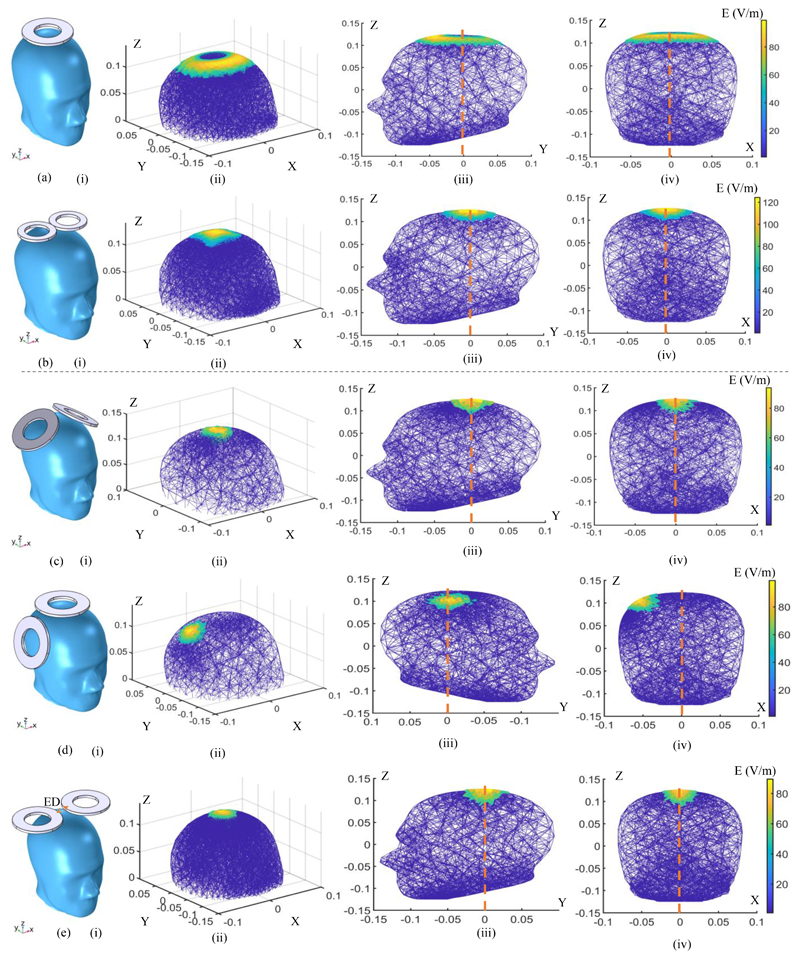
This study represents an initial investigation into the temporal interference characteristics in TMS systems. We have posited that the low-pass properties of the membrane employed in the TI-TMS research are primarily considerable for the optimal E-field focality-depth trade-off. The spatial distribution of the induced electric field for two commercial TMS coils (single circular and figure-8 coils) and three different scenarios for TI-TMS have been characterized in Fig. 4. The TI scenarios are simulated using two single circular coils. Fig. 4 helps to better understand the performance of the proposed system by comparing the TI-TMS method with two coils commonly used in TMS experiments. It illustrates the design, interpretation and development of the new magnetic stimulation modalities.
Figure 4.
FEM simulation of electric field distributions of the different coil models and orientations. (a) A Magstim 90 mm single circular coil (P/N 3192). (b) A Magstim 70 mm figure-8 coil (P/N 9925, 3190). (c) - (e) Two Magstim 90 mm single circular coils (P/N 3192) in different orientations with the effect of temporal interference (ED: edge distance). (i) The coil placement on the skull. (ii) Spatial distribution of the induced E-field. (iii) Distribution of the induced E-field on the YZ plane. (iv) Distribution of the induced E-field on the XZ plane. In all simulations, the coil stimulus is a cosine wave with an amplitude of ± 700 volts. For (a) and (b) the stimulus frequency is 2.5 kHz and for the temporal interference simulations the stimulus frequencies are set to 10 kHz and 10.04 kHz. All axes are written in meters.
In all simulations, the stimulus voltage peak was set to ± 700 V. All coils are assumed to be 2 mm above the scalp. At this voltage level and spatial distance, the maximum induced electric field on the scalp by the single-coil and the figure-8 coil are 100 V/m and 120 V/m, respectively. While the magnitude of the induced E-field is a well-known predictor of the neural activation, the stimulation threshold for the nerve tissues in the brain was set to Eth= 50 V/m. This means that electric fields stronger than this are capable of stimulating specific neuronal populations (suprathreshold) [1].
The single-coil structure (Fig. 4 (a)) was used in early TMS systems because of its geometric simplicity and easy construction [11]. However, these types of coils induce a ring-shaped electric field that is non-focal and stimulate a large area of the brain, as shown in Fig. 4 (a)(i-iv). Figure-8 type coils were introduced to improve the spatial targeting of a single-coil three decades ago [12] (Fig. 4 (b)). They have been one of the conventional choices for most focal and clinical TMS systems. Existing commercial coils can rarely exceed the depth-focality trade-off of this structure [1]. For the Magstim 70 mm figure-8 coil, the spatial distribution of the activated volume and the depth of the field penetration in the YZ and XZ planes are shown in Fig. 4 (b)(ii), (iii) and (iv), respectively.
The proposed concept for TI-TMS is examined by three arrangements of single-coils. In the first arrangement, the coils are at a 90-degree angle to each other, intending to stimulate the center of the head (central-midline) (Fig. 4 (c)). In the second arrangement, the coils are positioned at the same angle to each other, but the hand knob region is targeted at the primary motor cortex (Fig. 4 (d)). In the last structure, two coils are at 180 degrees to each other, targeting the central area of the brain (Fig. 4 (e)). In this orientation, the edge distance (ED) of the two coils is ED = 25 mm. Compared to the single and figure-8 coils, it is quantitively shown that by using the TI-TMS method more focal and deeper regions can be stimulated.
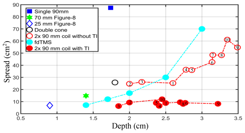
For the quantitative evaluation, the spread of the activated brain area (S [cm2]) is defined as the ratio of the stimulated volume (V [cm3]) to the depth of the electric field penetration (d [cm]) or S = V/d [1]. d is calculated as the radial distance from the surface of the cortex to the deepest point where the electric field exceeds the suprathreshold value. An increase in V or S corresponds to a decrease in focality. To compare the performance parameters of the designed system with state-ofthe-art equipment, the penetration depth-focality results for the structures listed in Fig. 4 are displayed in Fig. 5, along with the results of the Magstim 25 mm figure-8, the MagVenture double cone (DB-80) and the fdTMS coils. fdTMS coils, with a complex architecture, were introduced in 2018 by Gomez et. al to improve the focality and the depth of penetration [7]. In all coils, the voltage of the stimulus was adjusted so that the maximum induced electric field did not exceed 100 V/m. The Eth = 50 V/m was considered to predict the suprathreshold volume and the depth of penetration. For the concept of TI, different edge distances between the two coils in Fig. 4 (e) have been tested and evaluated, but for all scenarios, the Magstim 90 mm single circular coil was utilized. Additionally, the TI configurations, without interference (with two identical low-frequency electric fields) were also simulated and the penetration depth and spread are displayed in Fig. 5.
Figure 5.
Depth of penetration (d) and spread (S) of induced electric field for different coil structures. For temporal interference structures, the edge distance (ED) starts from 0 mm goes up to 45 mm, in steps of 5 mm (1 to 10 in red circles).
Compared to a Magstim 70 mm figure-8 coil, the average spread can be decreased by 23% in the TI-TMS approach while the penetration depth can be increased from 1.5 cm to 3.3 cm. Comparison of the proposed design’s results with all fdTMS coils also indicates either improved penetration depth or focality or both. In terms of energy, for matched 1.4 cm penetration depth from the head surface, the proposed TI-TMS method has twice the energy consumption of the figure-8 type coil, due to the need of two stimulation pulses in the TI concept. However, the designs presented for the square surface fdTMS coils have up to five times the energy consumption of the figure-8 coil to activate a depth of 1.4 cm.
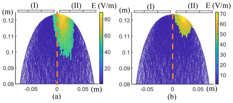
We next considered that by keeping the location of the coils constant while changing the stimuli voltage ratio, we could control the field beat locus, which in practice means steering the stimulation target from the center of the electric field interference. This feature is investigated in the configuration introduced in Fig. 4 (e), which can be extended to other orientations. The coil voltage ratios were adjusted from 1:1 (Fig. 4(e)(iv)) to 2:1 (Fig. 6(a)) and 4:1 (Fig. 6(b)). We observed that by changing the ratio of the stimuli amplitudes, while holding the voltage sum constant, the beat peak, and therefore the stimulated area, shifts and approaches the coil with the lower voltage. For the 2:1 case, the center of the stimulated area shifts 1.2 cm from the base center, and for the 4:1 case, the displacement is 2.43 cm. Therefore, the proposed structure will enable the live steering of the target area, without physical movement of the coils.
Figure 6.
Ability to steer the stimulated area by changing the voltage ratio of the coils, without changing their mechanical locations. The arrangement of the coils is as in Fig. 4(e) but; (a) Vcoil(I): Vcoil(II) = 2:1 (keeping the sum at 1.5 kV), (b) Vcoil(I): Vcoil(II) = 4:1 (keeping the sum at 1.5 kV).
In conventional TMS systems, the stimulus generator controls the temporal waveform of the pulses, while their spatial distribution depends on the mechanical configuration of the coils. The requirement for an accurate placement of the coil is more evident in fMRI-guided targeting TMS systems. To address this need, an image-guided robotically positioned coil system has been implemented [13]. Designing and manufacturing robotic systems that are compatible with neuroimaging methods are complex and costly tasks [14]. However, in our proposed system, the stimulus generator can dynamically change the targeted area and minimizes the need for robotic systems to physically move the coils.
In Fig. 7, we explore the effect of different voltage amplitudes of the stimuli on the electric field penetration depth, spread and maximum electric field in the proposed TITMS system and the figure-8 coil. For the finite element simulations of the TI-TMS technology, the structure of Fig. 4 (e) is chosen with an edge distance of 25 mm. As shown in Fig. 7 (a), for stimulus voltages above 500 volts, the TI-TMS modality can penetrate to a deeper target than figure-8 coils. As displayed in Fig. 7 (b), for fixed voltages, the advantage of the proposed method with regards to the spatial distribution and therefore the focality is evident. This advantage is more pronounced at voltages between 600 and 1100 volts (equivalent to a target depth of 2-4 cm for the TI-TMS). In terms of the maximum induced electric field (Emax), which is directly proportional to the stimulus intensity and one of the most important safety parameters of TMS-based systems [15], it is almost identical for the figure-8 coil and the proposed structure. The slight difference is due to the different geometries of the figure-8 and the single circular coils. The maximum E-field of the single-coil will be ring-shaped (Fig. 4 (a)(ii)), while for the figure-8 coil, the maximum field is seen at the intersection of the two coils (Fig. 4 (b)(ii)). Therefore, the maximum of the electric field and the electric field at the center of the head (Ecenter) are the same for the figure-8 coil and are shown in Fig. 7(c) by a single line. In the TI-TMS architecture, the E-field at the center of the head, where the intersection of the electric fields takes place and causes the temporal interference (Fig. 4 (e)(ii-iv)), has a different magnitude than the maximum electric field.
Figure 7.
Performance comparison of the suggested TI-TMS system and the Magstim 70 mm figure-8 coil for different coil voltages; (a) Depth of electric field penetration. (b) The E-field spread. (c) The maximum induced electric field (Emax) and its value at the center of the head (Ecenter)
We expect that the low-pass characteristic of the neuronal membrane will not allow the neurons to fire at the maximum electric field but that only the electric field in the interference locus will be able to engage the neurons. Therefore, it can be concluded that the magnitude of the electric field affecting the nerve is the magnitude of the field in the center (Ecenter). The field magnitude beneath the single-coils are approximately equal to the electric field produced by the figure-8 coil and should therefore not be a safety issue. In addition to the electric field intensity, the stimulus frequency and the number of pulses per minute are other crucial parameters that should be considered as TMS risk factors in future works [15] as this might limit the application of TI-TMS. It should also be noted that even though the neurons are not expected to follow the high-frequency stimuli, they may be activated in a different way [4]. Simulations show they might be activated when initially turning on the stimulation and then not react further.
The large number of continuous stimuli injected into the coil in the TI concept accumulates heat, and the heat dissipation in the coils naturally increases. This heat must be controlled and limited, for both hardware and patient safety. Therefore, for this high-speed stimulation system, an active cooling system is required, especially if it is intended to run repetitive protocols (rTMS) such as Theta Burst Stimulation (TBS) [15]. Liquid and gas-forced cooling systems can be utilized to reduce coil heating. The tendency of high-frequency pulses to flow close to the surface rather than through the center of the cable, reduces its effective cross-section and increases the effective resistance of the coil cable, a phenomenon known as the skin effect [16]. Choosing the right thickness considering the skin effect, can minimize the resistance loss and thus reduce the heat dissipation of the coil. Adding ferromagnetic cores can also help to cool the coils, in addition to focusing the magnetic flux more and possibly improving the penetration depth-spread of the activated region, as it will have a heatsink function [17] [18].
Finally, for the circuit implementation of the proposed system, the stimulus generator must produce high-frequency pulses. Since most generators are based on the LC oscillator architecture, higher frequencies can be achieved by choosing different capacitances for the capacitors. To generate a slight frequency difference (Δf), the target oscillation frequencies can be obtained by partial variations in the coil windings. The maximum stimulus frequency is determined by the hardware implementation restrictions of the pulse generator circuit. Also, the energy efficiency and ohmic losses of these circuits can limit the continuity of stimulus generation [19].
IV. Conclusion
The concept of temporal interference in magnetic stimulation systems has been proposed and evaluated. The primary goal of this paper is to improve the electric field depth-focality trade-off by integrating the intrinsic properties of neural tissues into the design of transcranial stimulation systems. Changing the stimuli voltage ratios could make it possible to spatially steer the stimulation location without mechanical coil movements. The architectural concept of TITMS is quite general and can be implemented with slight modifications to the pulse generator, without the need for sophisticated coil design. The high penetration depth and relatively low spread demonstrate the potential viability of a temporal interference approach in the introduction of novel TMS related technologies.
Acknowledgment
This work was supported by a programme grant from the MRC Brain Network Dynamics Unit at Oxford, as well as supplemental funding to Denison by the Royal Academy of Engineering and Wendt by an MRC iCASE fellowship.
Contributor Information
Memarian Sorkhabi Majid, Email: majid.memariansorkhabi@pharm.ox.ac.uk.
Wendt Karen, Email: karen.wendt@some.ox.ac.uk.
Denison Timothy, Email: timothy.denison@eng.ox.ac.uk, members of the MRC Brain Network Dynamics Unit, University of Oxford, Oxford, OX1 3TH, UK; Department of Engineering Science, University of Oxford, Oxford, OX1 3PJ, UK.
References
- [1].Deng Z, Lisanby S, Peterchev A. Electric field depth-focality tradeoff in transcranial magnetic stimulation: simulation comparison of 50 coil designs. Brain Stimulation. 2013 Jan;6(1):1–13. doi: 10.1016/j.brs.2012.02.005. [DOI] [PMC free article] [PubMed] [Google Scholar]
- [2].Cohen D, Cuffin B. Developing a more focal magnetic stimulator. Part I: Some basic principles. J Clin Neurophysiol. 1991 Jan;8(1):102–111. doi: 10.1097/00004691-199101000-00013. [DOI] [PubMed] [Google Scholar]
- [3].Hutcheon B, Yarom YR. oscillation and the intrinsic frequency preferences of neurons. Trends Neurosci. 2000;23:216–222. doi: 10.1016/s0166-2236(00)01547-2. [DOI] [PubMed] [Google Scholar]
- [4].Grossman N, Bono D, Dedic N, Kodandaramaiah SB. Noninvasive Deep Brain Stimulation via Temporally Interfering Electric Fields. cell. 2017 Jun;169(6):1029–1041. doi: 10.1016/j.cell.2017.05.024. [DOI] [PMC free article] [PubMed] [Google Scholar]
- [5].Cao J, Grover P. STIMULUS: Noninvasive Dynamic Patterns of Neurostimulation Using Spatio-Temporal Interference. IEEE Transactions on Biomedical Engineering. 2019 May 30; doi: 10.1109/TBME.2019.2919912. [DOI] [PubMed] [Google Scholar]
- [6].Peterchev A, TA W, Miranda P, Nitsche M, Paulus W, Lisanby S, Pascual-Leone A, Bikson M. Fundamentals of transcranial electric and magnetic stimulation dose: Definition, selection, and reporting practices. Brain Stimulation. 2012 Oct;5(4):435–453. doi: 10.1016/j.brs.2011.10.001. [DOI] [PMC free article] [PubMed] [Google Scholar]
- [7].Gomez LJ, Goetz SM, Peterchev AV. Design of transcranial magnetic stimulation coils with optimal trade-off between depth, focality, and energy. Journal of Neural Engineering. 2018 Jun 25;15(4) doi: 10.1088/1741-2552/aac967. [DOI] [PMC free article] [PubMed] [Google Scholar]
- [8].Hodgkin A, Huxley A. A quantitative description of membrane current and its application to conduction and excitation in nerve. The Journal of physiology. 1952;117(4):500–544. doi: 10.1113/jphysiol.1952.sp004764. [DOI] [PMC free article] [PubMed] [Google Scholar]
- [9].Perez R. Wireless Communications Design Handbook. Vol. 3. Academic Press; 1998. Chapter 3 - Noise Issues in High-Performance Mixed-Signal ICs and Other Communications Components; pp. 103–193. [Google Scholar]
- [10].Yuan Y, Chen Y, Li X. Theoretical Analysis of Transcranial Magneto-Acoustical Stimulation with Hodgkin-Huxley Neuron Model. Front Comput Neurosci. 2016;10(36) doi: 10.3389/fncom.2016.00035. [DOI] [PMC free article] [PubMed] [Google Scholar]
- [11].Barker A, Jalinous R, Freeston I. Non-invasive magnetic stimulation of human motor cortex. Lancet. 1985 May;11(1):1106–7. doi: 10.1016/s0140-6736(85)92413-4. [DOI] [PubMed] [Google Scholar]
- [12].Ueno S, Tashiro T, Harada K. Localized stimulation of neural tissues in the brain by means of a paired configuration of time-varying magnetic fields. Journal of Applied Physics. 1988;64(10):5862–5864. [Google Scholar]
- [13].Lefaucheur J-P. Why image-guided navigation becomes essential in the practice of transcranial magnetic stimulation. Neurophysiologie Clinique/Clinical Neurophysiology. 2010 Mar;40(1):1–5. doi: 10.1016/j.neucli.2009.10.004. [DOI] [PubMed] [Google Scholar]
- [14].Sparing R, Dorothee B, Ingo GM, Tomás P, Gereon FR. Transcranial magnetic stimulation and the challenge of coil placement: A comparison of conventional and stereotaxic neuronavigational strategies. Human brain mapping. 2008;29(1):82–96. doi: 10.1002/hbm.20360. [DOI] [PMC free article] [PubMed] [Google Scholar]
- [15].Rossi S, Hallett M, Rossini bPM, Pascual-Leone A. Safety, ethical considerations, and application guidelines for the use of transcranial magnetic stimulation in clinical practice and research☆. Clin Neurophysiol. 2009 Dec;120(12):2008–2039. doi: 10.1016/j.clinph.2009.08.016. [DOI] [PMC free article] [PubMed] [Google Scholar]
- [16].Idir N, Weens Y, Franchaud JJ. Skin effect and dielectric loss models of power cables. IEEE Transactions on Dielectrics and Electrical Insulation. 2009 Feb;16(1):147–154. [Google Scholar]
- [17].Memarian Sorkhabi M, Frounchi J, Shahabi P, Veladi H. Deep-Brain Transcranial Stimulation: A Novel Approach for High 3-D Resolution. IEEE access. 2017 Feb;5:3157–3171. [Google Scholar]
- [18].Epstein CM. TMS stimulation coils. Oxford Handbook of Transcranial Stimulation. 2008 Oxford Handbooks Online. [Google Scholar]
- [19].Memarian Sorkhabi M, et al. Measurement of transcranial magnetic stimulation resolution in 3-D spaces. Measurement. 2018;116:326–340. [Google Scholar]


