Abstract
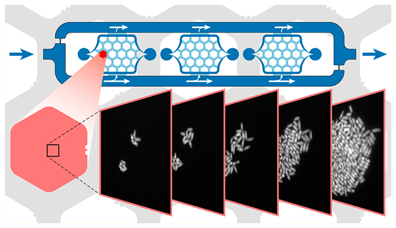
Optical long-term observation of individual cells, combined with modern data analysis tools, allows for a detailed study of cell-to-cell variability, heredity, and differentiation. We developed a microfluidic device featuring facile cell loading, simple and robust operation, and which is amenable to high-resolution life-cell imaging. Different cell strains can be grown in parallel in the device under constant or changing media perfusion without cross-talk between the cell ensembles. The culturing chamber has been optimized for use with nonadherent cells, such as Saccharomyces cerevisiae, and enables controlled colony growth over multiple generations under aerobic or anaerobic conditions. Small changes in the layout will make the device also useable with bacteria or mammalian cells. The platform can be readily set up in every laboratory with minimal additional requirements and can be operated without technology training.
Microscopic long-term observation of individual cells and their offspring is used to address a wide variety of biological questions, such as cell fate decisions in mammalian cells,1 growth and cell cycle regulation in yeast2, how bacterial cells acquire antibiotic resistance,3 or how cells inherit cytoplasmic factors.4 Although the biological questions and model systems may be quite diverse, the experiments needed to answer those questions require, in most cases, a precise and comprehensive control of the cellular environmental parameters and subcellular-resolution observation methods. Restriction of cell proliferation to a defined focal plane, which essentially yields a monolayer of cells, facilitates time-lapse imaging with high-resolution objectives and enables the use of automated image analysis methods. Classical experimental approaches to achieve cell growth within a defined focal plane involve embedding cells on a coverslip surface by using either gelatin5 or agar drops6 or by adhering cells on the surface of a coated coverslip.7 More recent approaches rely on controlled perfusion systems and microfluidic devices.8,9 Microfluidic devices offer the possibility to confine cell arrangements to a twodimensional layer and enable precise temporal and spatial control of fluid volumes. Further, they can be used for longterm cell cultivation, as experimental conditions can be controlled and maintained for the whole duration of the experiment.
Ideally, one would like to have a broadly applicable device that is straightforward to fabricate, assemble, and apply, also, in nonspecialized laboratories (use of standard laboratory equipment). The device should be user-friendly and robust in operation also over an extended time (no clogging, no bubbles). Further, it should provide good control of environmental conditions (temperature, nutrient, oxygen supply, etc.) and be accessible to high-resolution automated microscopy.
Currently available systems often have been specifically developed for a certain application and the targeted cell type and associated growth conditions or experimental duration. 2D growth restriction for nonadherent cells can be achieved by creating patches for cells in which cellular extension or movement is only allowed in the horizontal plane, whereas cells that adhere to surfaces naturally grow in 2D. In current designs nonadherent cells are often clamped between a soft PDMS layer and a glass slide. Cells are, for example, introduced into low-height cultivation chambers that are constructed as side pockets of a perfusion channel10–17 or low-height areas between two parallel flow channels.18–21. For loading of cells into such chambers, the cells either feature similar vertical extension as the chamber height, or the PDMS chamber ceiling needs to be temporarily lifted up through pneumatically generated forces. Loading yield relies on a statistical process and can be tuned by varying the cell density in the applied cell suspension. A better control of the cell loading process can be achieved by using, for example, Tesla-diode-like chamber shapes10 or vacuum-assisted cell loading procedures.12,16,17 Cells can also be directly transferred into the cultivation chamber via pipettes22 and DNA array spotters20 before the final assembly step of the devices. Alternative approaches for experiments with observation of 2D cell arrangements include trap structures,23,24 the use of micropads,25,26 or clamping of the cells between a PDMS layer and a semipermeable membrane, which then enables vertical medium transfer to the cells.27 Cells have also been immobilized in culture chambers by using agarose gel to protect them against wash- off.28 Many of the devices described above enable microscopic analysis of cells over an extended period of time under controlled environmental conditions, in some cases, in a massively parallel way, and they provide detailed insights into biological processes at the single-cell level.
There is, however, not an all-in-one device suitable for every purpose. Massive parallelization, for example, requires multilayer devices and highly sophisticated setups. The use of side pockets for cell immobilization only allows for medium supply through diffusion and renders cell removal challenging so that the overall number of observable cells and the experiment durations are limited. Cell loading through small deformations of elastic layers underneath which cells then are clamped can be tedious.
Here, we report on a microfluidic device, which enables culturing of different cell types ranging from bacteria to mammalian cell culture with a diverse set of growth conditions and protocols over a long period of time, while handling and operation are straightforward and simple. All cells are kept in the focal plane rendering the device compatible with high-resolution time-lapse imaging. Nonadherent cells are clamped under growth pads, and medium supply is through a combination of diffusion and pressure-driven flow in the culturing chamber, while adherent cells are grown under small medium flow. Efficient nutrient renewal is demonstrated, and different levels of oxygenation (aerobic or anaerobic conditions) can be set and tightly controlled to ensure defined cell growth conditions. The flow architecture is simple, media exchange is rapid, air bubbles are efficiently removed, and overgrowing cells are rapidly and sustainably washed away. At the same time, device fabrication, cell loading, and microfluidic culturing are simple and robust. The fabrication requires only two PDMS molds. Cell and medium loading includes a few pipetting steps, and the chip can be operated with a single syringe pump. The system design can be adapted to different cell types and parallel experiments.
Experimental Section
Fabrication of the Microfluidic Chip
The microfluidic chip consists of two layers of poly(dimethylsiloxane) (PDMS), bonded to a 150 μm thick cover glass (24 mm × 60 mm). Both PDMS layers were casted from the respective molds that have been fabricated by using well-established multilayer SU-8 photolithographic processes on 4 in. silicon wafers (Figure S-1).
Fabrication of the Oxygen-Sensitive Layer
Polystyrene was dissolved in toluene and supplemented with Pt(ll) octaethylporphine ketone (1 g/L). A total of 1 mL of the PS/ toluene/PtOEPK solution was spin-coated on a cover slide and left to dry at room temperature. PDMS was then spin-coated on top and cured. The coated slides were kept in a dark place at room temperature until further use.
Loading of Cells and Microfluidic Cell Culturing
Cells were cultured using standard protocols (see Supporting Information) and were diluted to specified cellular concentrations. PDMS device and glass slide were rinsed with acetone and isopropanol and dried using a nitrogen gun. Both were then placed in the plasma oven and left in vacuum for 20-30 min for PDMS degassing. The oxygen plasma was then switched on for 20 s. Alternatively, a conventional vacuum desiccator for degassing and a hand-held corona discharge device for PDMS surface treatment29 can be used. Right after activation, 0.45 μL of cell solution (0.8 μL for mammalian cells) was serially pipetted onto each culturing area by using a conventional pipet. The cover glass was placed on top and slightly pressed down onto the PDMS. Irreversible bonding was achieved upon first PDMS-glass contact (after approximately 30 min when using the corona discharge device). The perfusion channel was filled from the inlet and outlet with medium, and the device was then transferred to the microscope. The microfluidic device was placed on a custom-made chip holder. Prefilled tubing was used to connect a syringe pump to the outlet and a medium reservoir to the inlet. The vacuum port was connected to house vacuum. Bubbles introduced during loading were removed in less than 1 h. After an initial settling time, the pump was switched on and adjusted to a specific pump rate.
Automated Time-Lapse Imaging
Microfluidic cell culture experiments were performed on a NIKON Ti Eclipse inverted fluorescence microscope, placed in an environmental box to control temperature. For mammalian cell cultures, a stage-top incubator was used to additionally control humidity and CO2 levels (5%). The microscope was driven either by NIKON NIS-Elements Advanced Research software or by using YouScope.17 Image analysis was carried out using Matlab, ImageJ, and CellX.18
Please refer to the Supporting Information for more detailed and further experimental procedures, including fabrication of the microfluidic chip, cell culture, measurements of medium exchange, fabrication of the oxygen sensitive layer, testing of oxygen limitation, pHluorin experiments, COMSOL simulations, and image analysis.
Results And Discussion
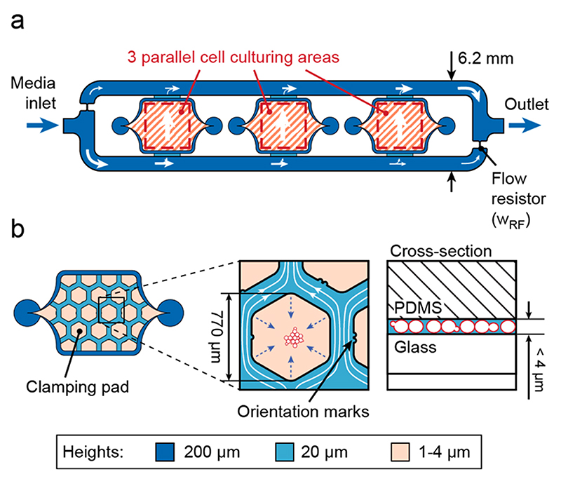
The cells are cultivated on a 150 μm thick cover glass slide to render the microfluidic device compatible with fully automated, high-resolution optical microscopes and commercial hardware autofocusing systems (e.g., Nikon Perfect Focus System). The microfluidic system includes three chambers with cell culturing areas (3 mm × 3 mm, 20 μm high), surrounded by a media supply system (Figure 1a). The relatively large area is able to accommodate the liquid volume dispensed through a conventional pipet (>0.1 μL) with manual alignment. The parallel arrangement of the three chambers allows for simultaneous cultivation of three different cell strains. Their internal layout (red-shaded area) was adapted with respect to the cell type of interest. Adherent cells are cultured directly in the 20 μm high chambers (see below). Nonadherent cells, which are in the focus of this work, are grown under hexagonal pads (770 μm wide) arranged in a honeycomb configuration. Compared to micropads,26 the large pads allow for observing large populations of cells. A total of 10 pads provide a substantial number of replicas and starting points, since not all initially chosen cells grow as expected. A perfusion network is implemented in the space between the hexagonal pads. The height of the chamber has been adjusted between 1 and 4 μm in the area of the pads in order to efficiently clamp cells of different sizes (Figure 1b). Different devices were fabricated to achieve different heights. The microfluidic structure was fabricated through PDMS casting from SU-8/silicon molds (see Experimental Section and Supporting Information).
Figure 1. Microfluidic chip layout.
(a) Top view of the chip consisting of three cell culturing areas surrounded by a 200 μm high channel for nutrient supply. (b) Design of the culturing area for nonadherent cells. Hexagonal PDMS pads clamp cells on the thin glass slide and constrain movement to the focal plane.
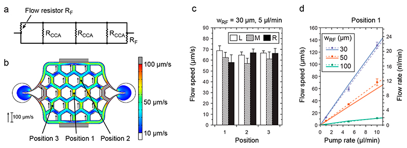
The three chambers are surrounded by a large channel to supply nutrients through continuous perfusion for long-term cultivation (200 μm high). This channel was designed as a single input/output system with built-in flow resistors (narrowing of the channel, w RF), which guarantee a controlled, parallel, and unidirectional flow through the culturing chambers and can be described by using a simplified electrical circuit model (ECM; Figure 2a). The flow through the chambers is set up by a pressure difference between the upper and lower branch of the channel, which can be adjusted by varying the width of the flow resistor, wRF, and the external pump rate (Figure S-2). The pump rate is applied by using a single syringe pump in withdraw mode connected to the outlet (>1 μL/min). The inlet of the chip is connected to a medium reservoir. To characterize the flow in the chambers and to validate the electrical circuit model, we manually measured the maximal flow speeds at different points in the chamber by using small beads and compared the obtained values to the predicted ones. The simulation results (color scale) and measurement results (black arrows beside with length scale) are in good agreement (Figure 2b). Additionally, the flow speed variations across the chamber are small (<10%), and the flow speed is similar in the three different culturing chambers, which ensures comparable flow conditions that are independent of the position within the microfluidic device (Figure 2c, same experimental conditions as in Figure 2b). To test the range and resolution of the flow control within the chip, we constructed a series of chips with smaller or larger flow resistors, wRF, and applied different pump rates (1, 5, and 10 μL/min). We measured the maximal flow speeds for the different configurations. The measured values (circles) and linear fits (dashed lines) are plotted in Figure 2d together with the predicted values (solid lines) using the finite- element modeling. Again, prediction and measurement are in good agreement (slope variations <7%). The right axis in Figure 2d indicates the obtained flow rates in the channel at position 1, where the channel is 20 μm high and 207 μm wide.
Figure 2. Flow in the culturing chamber.
(a) Simplified electrical circuit model illustrating the parallel flow configuration in the microfluidic chip and displaying the respective flow resistances. The two flow resistors, RF, are used to modulate the flow through the cell culturing areas (flow resistance: Rcca). (b) A COMSOL CFD simulation (color scale, values higher than those represented on the scale bar, that is, >100 μm/s are marked in gray, values lower than those on the scale bar, that is, <10 μm/s are marked in white) shows a homogeneous distribution of the flow speeds in the entire culturing area, except the very left and right peripheral channels, and is in good agreement with flow speed measurements of beads (lengths of black arrows). Results are for W rf = 30 μm and a pump rate of 5 μL/min. (c) Comparable maximal flow speeds measured at three different positions (indicated in (b)) in all of the three culturing areas: L (left), M (middle), and R (right; n = 5, mean ± s.d.) for W rf = 30 μm and a pump rate of 5 μL/min. (d) Simulation (solid lines) and measurements (filled circles with error bars and linear fit, dashed lines) showing the variability of applicable flow speeds in the center of the culturing area (position 1 in (b)) for different w RF and different pump rates (n = 5, mean ± s.d.). The right ordinate displays the respective flow rates calculated for a channel of 20 μm height and 207 μm width.
The presented design enables a simple, pump-rate dependent control of the flow speed and associated shear stress inside the cultivation chambers over a relatively large range. Further, the relatively high external pump rates (1 to 10 μL/min, provided by conventional syringe pumps) allow for rapid medium transfer from the external reservoir through the tubing into the chip (~2 min, depending on the tubing volume). This feature allows for attaining aerobic growth conditions with oxygenated medium in the culturing chambers by simply bubbling oxygen through the external medium reservoir. The flow through the culturing chamber is then, however, uniformly reduced on-chip and can be varied for different cell types through variation of the flow resistor design in the parallel flow configuration.
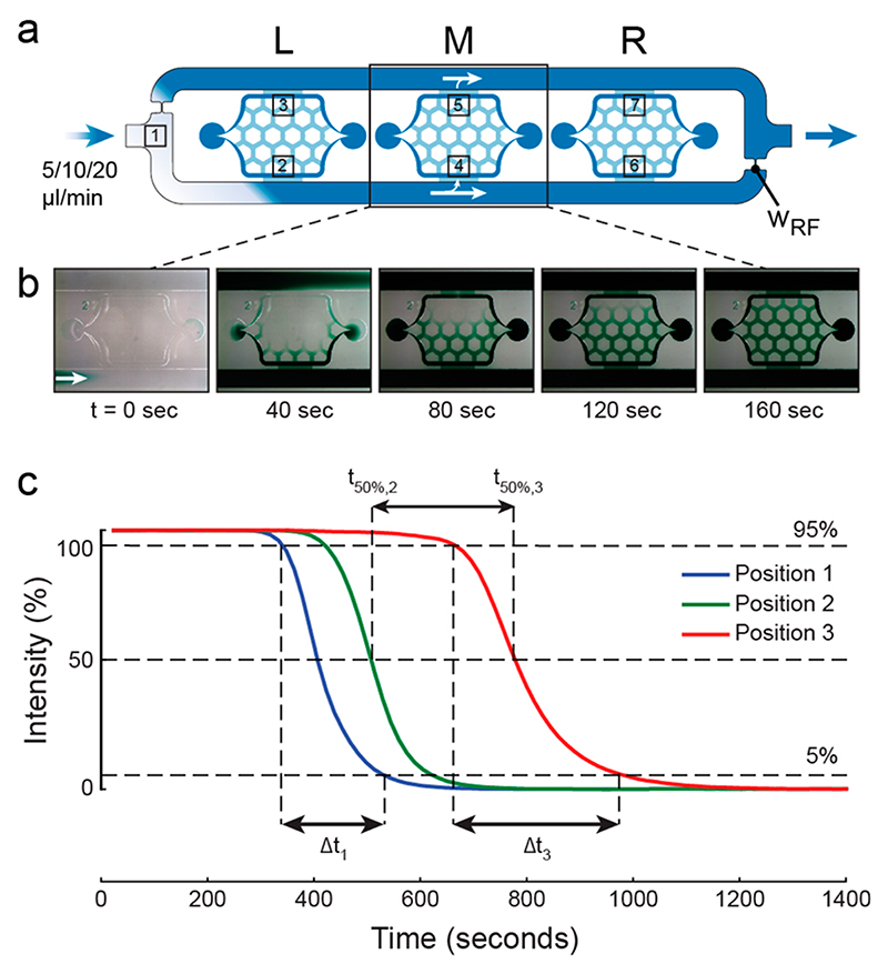
The total volume of one cell culturing area without pads is ~300 nl (~100 nl with pads). This is small compared to the applied pump rates and allows for a rapid medium turnover in the whole culturing chamber. We characterized the medium exchange dynamics of the different chip designs by infusing noncolored liquid and then switching to colored liquid (Figure 3a). A complete medium turnover in a culturing chamber is exemplarily illustrated in Figure 3b with green food dye. The colored liquid absorbs light and, therefore, reduces the gray scale values recorded by our CCD sensor at seven positions in the chip. Using the resulting intensity versus time curves, we measured the complete medium turnover of a chamber, the absolute dispersion of the liquid at each position, as well as the increase in dispersion (Figure 3c exemplary for positions 1, 2, and 3) for different pump rates and flow resistors (w RF). As expected, the complete media turnover depends on both, the pump rate and the nature of the flow resistor and can be as fast as 30 s or as slow as 500 s (Table S-1). At the single pad level, a complete medium switch is even faster and can be brought down to the second range (Table S-2). We measured the medium exchange under the low-height pad for a pump rate of 10 μL/min and a flow resistor width of 50 μm (Figure S-3). The time for a complete turnover of the medium at the center of the pad amounted to 12 s, while a delay of ~27 s was observed with respect to the pad periphery. Given the option of rapid media transfer from the media reservoirs to the chip within reasonably short time scales, it is possible to achieve fast media switches by simply manually exchanging the media reservoirs.
Figure 3. Medium exchange.
(a) Overview of the microfluidic chip indicating the positions, where intensities have been measured after liquid switch at the chip inlet. (b) Time-lapse photographs of the central chamber illustrating the liquid turnover with green food dye (pump rate was 10 μL/min and W rf = 50 μm). (c) Intensity changes at positions 1, 2, and 3 in the chip as a result of a medium switch at the inlet (pump rate was 10 μL/m, W rf = 100 μm).
Air bubbles are a common problem in microfluidics-based long-term cell cultivation whether introduced during the loading procedure or randomly generated during the experi-ment. Bubbles disrupt the experiment by blocking or limiting the medium exchange or by direct shear-induced damage upon hitting the cells. Common solutions to the bubble problem include dedicated microstructures upstream of the cell compartment, where bubbles are either trapped and prevented from entering the microfluidic device,30 or trapped and removed through use of gas-permeable material like PDMS31,32 or use of a liquid−air interface.33 These structures, however, do not prevent bubble formation within the chip during operation. We added a microfluidic channel structure above the large medium channels that surround the culture chambers in a second PDMS layer and connected this channel structure to vacuum (Figure 4a). We then applied vacuum to the channel structure above the chambers over the full duration of the experiment and, thereby, continuously removed bubbles in the medium channels through the 1 mm thick gas-permeable PDMS membrane. With this approach, even large bubbles could be removed in less than 30 min, which ensured robust long-term medium perfusion in all culturing chambers (Figure 4b).
Figure 4. Bubble removal in the microfluidic chip.
(a) Schematic top view and cross-section (not to scale) of the chip including the vacuum channel above the perfusion channel. (b) Results of vacuum-assisted bubble removal using in-house vacuum (−600 mbar). An intentionally introduced bubble of 0.3 μL volume could be removed in less than 30 min (cf. graph and bright field images at different time points). The PDMS layer between fluidic and vacuum air channel is 1 mm thick. A permeability of air through PDMS of 935 Barrer has been calculated, a value which is comparable to literature.34 The removal rate for t = 0 is 39 nL/min. Without vacuum, no reduction in the bubble volume was visible for at least 4 h (data not shown).
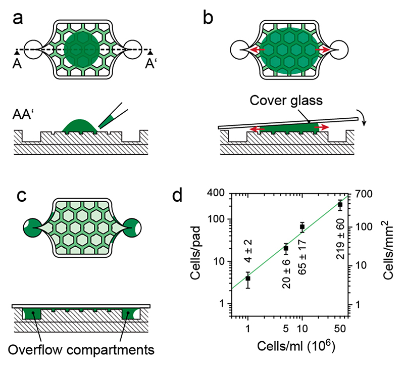
The ease of handling is probably the most important criterion in determining the success of a technology. Loading of cells into the microfluidic devices may constitute a very tedious and time-consuming procedure. Here, we only suspend the cells in solution at desired concentrations and then manually transfer this solution to the growth chamber structures (Figure 5a). The relatively large culturing areas can hold volumes between 0.4 and 0.8 μL, which can be easily applied with a standard pipet. The chip is then closed by applying a coverslip, thereby distributing and clamping the cells in the growth chambers (Figure 5b). The clamped cells themselves prevent the ceilings from collapsing. To seal the device, an irreversible PDMS-glass bond has to be formed, so that the PDMS structure has to be plasma-activated prior to cell loading. Further, it is necessary to prevent PDMS deactivation between the chambers due to overspreading of media during cell loading. The loaded liquid volume is largely exceeding the volume of the cell-culturing chamber (<300 nl). While Lovchik et al.22 relied on controlled overflow by using capillary forces, overflow is prevented here by the specific shape of the culturing chamber, which causes excess liquid to flow to a trench surrounding the chamber and then sideways into overflow compartments (red arrows). Medium exchange in these overflow compartments is relatively low so that cell growth is reduced. The liquid loading and device sealing procedure produces entrapped air bubbles in the microfluidic channels (Figure 5c). Through degassing of the PDMS device for 20 min in an oxygen plasma oven prior to loading, air bubbles introduced during loading are taken up in the bulk PDMS after sealing the device. Liquid loading volumes are large enough to prevent any dry-out and related cell stress, which may be observed upon spotting smaller volumes.
Figure 5. Schematic side and top view of one chamber illustrating the cell loading procedure of the chip.
(a) Cells are directly pipetted onto the cell culturing area of the plasma-activated PDMS device. (b) A thin cover glass (24 mm × 60 mm) is placed on top, which distributes and clamps the cells between the hexagonal pads and the glass. (c) Excess medium is guided sideways into the overflow compartments, which ensures a tight bonding of the glass to the activated PDMS surface. (d) Number of cells clamped under one pad (left axis) and per area (right axis) for suspensions of different cell concentrations (manually counted for five pads during three loading procedures, n = 15).
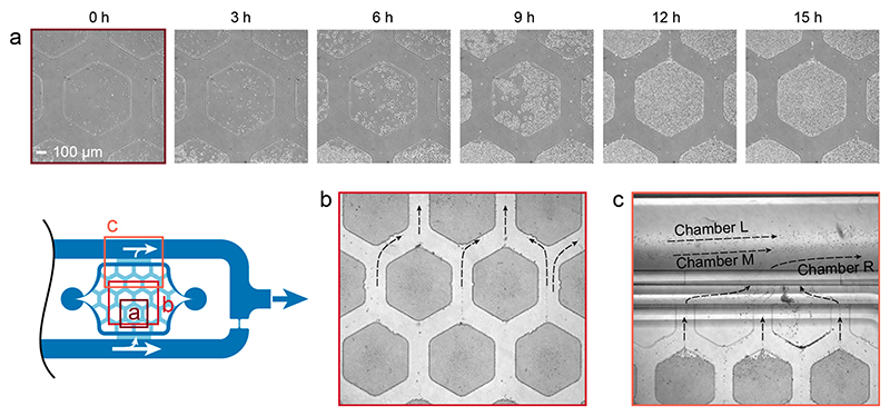
Once cells were clamped below the pads, they started to grow and proliferate within the height-limited space between PDMS and glass slide. We tested the basic operation principle by growing nonadherent Saccharomyces cerevisiae cells in rich media containing 2% glucose. We loaded the cells at a rather high density of 5 × 10⁷ cells/mL, so that multiple individual S. cerevisiae cells were clamped under one growth pad and we then observed the formation of 2D colonies. The cells were able to grow for >10 generations under anaerobic conditions (Figure 6a). Once the colony reached its maximal size (when the hexagonal pad was completely filled), the cells started to fall into the perfusion channels along the sides of the hexagonal pads. Due to the constant and homogeneous flow through the culturing chambers (see above), overgrowing cells from the growth pads were washed away efficiently, which is an important feature to prevent clogging of the chip during long-term experiments. Additionally, the homogeneous and laminar flow regime in the culture chamber prevented crossover of washed-off cells between the different pads (Figure 6b). The parallel arrangement of the culturing areas, combined with the laminar flow in the surrounding medium channels, prevented cells and medium from one growth chamber entering neighboring ones. The probability of cross contamination between the different chambers is, therefore, very low (Figure 6c).
Figure 6. Cell growth and wash away.
(a) Phase contrast time-lapse micrographs (Plan Fluor 10X Ph1) of S. cerevisiae cells, loaded at a density of 5 × 10⁷ cells/mL, and their proliferation until complete pad filling after 15 h (see Video S-1 for full time-lapse movie). (b) Overgrowing cells are washed away by the constant medium flow between the hexagonal pads (bright field micrograph, Plan Fluor 4X). Laminar streamlines minimize cell crosstalk between different pads (see also real-time Video S-2). (c) Cells leaving the cell culturing area exit the chip through the perfusion channel surrounding the culturing chambers (bright field micrograph, Plan Fluor 4X). The parallel chamber arrangement prevents cells from one cell
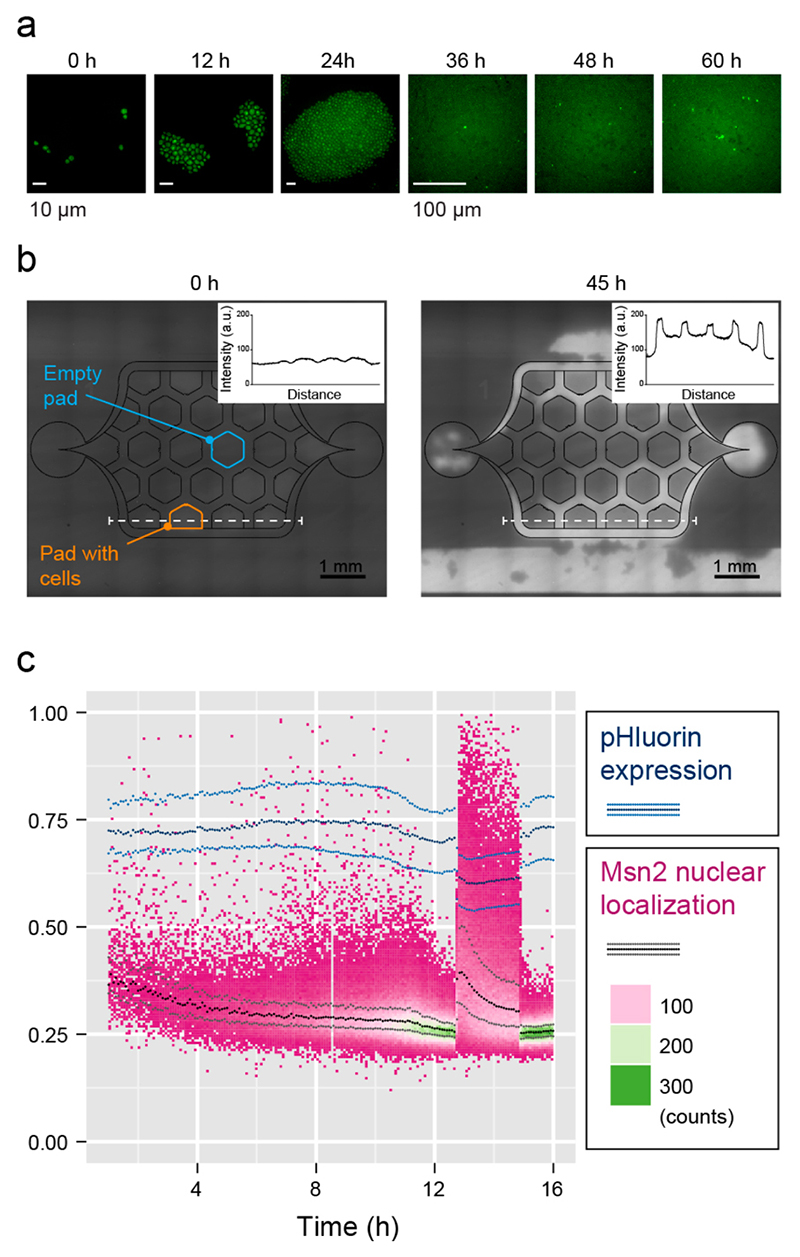
A key issue in long-term cultivation is to provide identical experimental conditions throughout the experiment without limitations in nutrients or oxygen supply. To characterize whether S. cerevisiae is able to grow unperturbed in our microfluidic system, we monitored the localization of the endogenously tagged transcription factor Msn2. Msn2, usually present in the whole cytoplasm, localizes to the nucleus under a wide variety of stressful conditions, such as C-limitation, oxygen depletion, or osmolarity changes.35–37 First, we monitored the oxygen supply by growing S. cerevisiae in ethanol as the sole carbon source. We found that the chip enabled unperturbed measurement of ethanol-dependent (aerobic) S. cerevisiae growth for more than 20 generations without increased cell death or cell-cycle slow-down in the center of the growth pads (Figure 7a). The transcription factor Msn2 was activated sporadically in individual cells, independent of their spatial location on the chip.38 As Msn2 is notoriously difficult to monitor, our experiments also demonstrate that the chip can be combined with imaging methods requiring large magnification and high numerical-aperture objectives.
Figure 7. Unstressed growth.
(a) S. cerevisiae cells bearing endogenously GFP tagged Msn2 were grown in yeast extract peptone (YP) +3% ethanol (Apo 60X Oil, loading density of 107 cells/mL, see Video S-4 for full time-lapse movie). (b) Oxygen availability was measured by bonding the chip to a coverslip coated with the oxygensensitive fluorescent dye Pt(II) octaethylporphine ketone (PtOEPK). S. cerevisiae cells were grown aerobically using ethanol as carbon source until a part of the culture pads were full (t =0 h); the medium flow was then reduced to allow for accumulation of cells (t = 45 h). This condition does, however, not reflect normal chip operation. Increased PtOEPK fluorescence indicates oxygen depletion on the one hand under the pads (see intensity scales of insets) and at locations of cell accumulation, predominantly in the larger channel volumes (for a complete figure set see Figure S-5). (c) S. cerevisiae cells expressing endogenously tagged Msn2-mKOkappa and bearing constitutively expressed pHluorin were grown in YP+2% glucose for 13 h. After 13 h, the input was switched to YP+0% glucose for 2 h and, subsequently, switched back to YP+2% glucose. Fraction of detected Msn2- mKOkappa fluorescence intensity that occurs inside the cell nuclei versus time (heat map and black/gray lines) and pHluorin emission intensity ratio recorded at 400 and 480 nm excitation vs time (blue lines). The lines indicate the 25%, median, and 75% quartiles. Note that cell number (counts) increases over time.
To further characterize oxygen availability in our culturing chambers, we coated the coverslip with the oxygen-sensitive Pt(ll) octa-ethylporphine ketone (PtOEPK) dye. PtOEPK fluorescence is quenched by high oxygen concentrations. We monitored fluorescence in chips with pads fully covered by S. cerevisiae cells under ethanol carbon source conditions (Figure 7b). We noticed a slight increase in the fluorescence intensity under growth pads that were completely filled with cells as compared to empty pads and surrounding fluidic channels, which remained dark. The fluorescence intensity did not further increase toward the middle of the pads and was independent of the relative position of the pad in the chamber. To test, whether this readout is reliable, we produced hypoxic conditions in the chip by substantially lowering the flow rate. The fluorescence intensity under the pads under these conditions showed a visible increase in fluorescence (intensity curves in Figure 7b). An even stronger increase, however, was detectable in regions where larger colonies of cells grew or clogged the fluidic structures. These experiments prove that the oxygen supply is sufficient to grow cells in the device under aerobic conditions, as neither the Msn2 nuclear localization nor the PtOEK fluorescence pattern indicated hypoxic conditions.
S. cerevisiae cells grow faster on glucose than on ethanol, and, concurrently, their overall metabolic activity is then higher and the nutrient demand larger. We monitored whether the cells experience an insufficient supply of nutrient by monitoring Msn2 localization in cells perfused with rich media containing excess glucose (≥2%). As long as glucose was present in the perfusion medium, Msn2 remained in the cytoplasm (Figure 7c, heat map, black lines), and no location-specific effects were observed throughout the device. Since Msn2 localization to the nucleus is transient and counteracted by the carbon-starvation activated Snf1 kinase,39 we additionally monitored the intracellular pH in the same cells. Cells starved for glucose experience a considerable and sustained drop in their cytoplasmic pH, which can be monitored by using the radiometric fluorescence protein pHluorin.40 We tracked the median and the 25% and 75% quartiles of the pH-dependent absorption ratio of pHluorin (Figure 7c, blue lines). As long as the cells grew in medium containing 2% glucose, the pHluorin ratio stayed approximately constant. Upon starving the cells by switching to medium not containing any glucose, the pHluorin ratio dropped, and the Msn2 localized to the nucleus. Importantly, both effects were reversed upon renewed addition of glucose to levels before the medium switch. Taken as a whole, S. cerevisiae were able to grow for >20 generations in medium with sufficient concentrations of the respective carbon source (>2%) and oxygen.
Microfluidic devices should be able to accommodate different cell types while forming part of the same experimental setup. To demonstrate use with different cell types, we took the same chip to monitor growth of Schizosaccharomyces pombe (Figure 8a), after adjusting the pad height to 4 μm, and the growth of bacteria, such as Pseudomonas putida over multiple generations (Figure 8b), after adjusting the pad height to 1 μm. Both cell types grew well in our chip. Next, we used a similar chip design to monitor the culturing and growth of adherent cells. Adherent cells can cope with low flow and can, therefore, be cultivated on the bottom glass of a 20 μm high culturing compartment without additional clamping structure. Small pillars are, however, necessary to stabilize the growth chamber ceiling (Figure 8c). Different mammalian cell types showed normal growth under continuous flow. The low flow produced little shear stress and high enough medium exchange rates to maintain pH values amenable to cell growth (Figure 8d, e, Figure S-4). The same microfluidic chip design has also been used to monitor CO2-controlled transgene expression in HEK293 cells over two days.41
Figure 8. Growth of different cell types in the microfluidic chip.
(a) Fluorescence time-lapse micrographs (GFP, Apo 60X Oil) of S. pombe cells expressing the GFP tagged integral endoplasmatic reticulum membrane protein ERG11 using a pad height of 4 μm (see Video S-5 for full time-lapse series, loading density was 107 cells/mL). (b) Bright field image (100×) of a P. putida bacterial colony grown under a 1 μm pad; the picture is slightly out of focus. (c) Design of the adapted culturing chamber for adherent cells. The chamber is 20 μm high and comprises stabilization pillars. The loading procedure remains the same. For details of flow characteristics, please refer to Figure S-3. (d) Phase contrast micrographs (Plan Fluor 10X Ph1) of a single HepG2 cell and the derived grown colony after 120 h in the chamber under continuous perfusion conditions (see Video S-6 for full time-lapse series). (e) Fluorescence micrographs (Plan Fluor 10X Ph1) of HCT116 GFP cell line proliferation during 120 h in the chamber under continuous perfusion conditions (see Video S-7 for full time-lapse series).
In all cases, the device allowed for stress-free long-term cultivation of cells while enabling diffraction-limited imaging of the wide variety of cells under different growth conditions (see also Figure S-6 for extended time-lapse series).
Conclusion
We developed and implemented a simple and easy-to-use microfluidic cell-culturing device. The hallmarks of the device include the long overall culturing time due to inherent removal of excess cells. The relatively fast switching times combined with the rapid media transfers from the media reservoir to the chip results in reasonably short delay times (<30 s are achievable) and enable aerobic growth conditions as well as media exchange experiments. We showed that our device is suitable for large-magnification and high-numerical-aperture objectives that can be used for long-term microscopic observation with a stable focus by using far-red light based hardware autofocusing systems. Due to its simple fabrication and its ease of handling, the device can be used and operated by nonexperts in almost any laboratory with minimal additional requirements and minimal training. Although the presented chip version includes only three culturing chambers, the number can be readily increased without changing the overall concept or characteristics: (i) By changing the device design, more chambers can be included between the two branches of the perfusion channels through extension of the device length, which then all have the medium conditions; alternatively several identical channel and chamber layouts can be arranged side-by-side in a new design, while each channel and chamber configuration has its own in- and outlet, and, therefore, different medium conditions. (ii) By assembling more than one of the presented devices side by side on a glass slide, whereat again, each device has its own inlet and outlet (different medium conditions). Further, the device can be conveniently adapted to host more delicate cell types, such as stem cells, or modified to feature structures for precisely timed medium switches or dosage sequences.
The size of one of the hexagonal pads (770 μm diameter) in the culturing chamber is large enough to enable the observation of cell colony formation and lineage tracking to study heredity phenomena. The medium flow can be easily adapted and controlled by the off-chip pumps and the device flow resistor designs. The presented microfluidic layout features a large liquid influx for rapid medium exchange, fast medium outflux for efficient waste and cell removal, and a homogeneous, low flow through the culturing chambers that can be adjusted for different cell types. The cell loading process includes only simple pipetting steps. The loading procedure is fast, robust and amenable to all tested cell types. The system is robust in operation, in particular with respect to air bubble formation and channel clogging by rapidly proliferating cells. Controlled and constant medium perfusion or changes of media perfusion without cross-talk between the different culturing chambers have been demonstrated. While the device has been extensively characterized with standard rich media, further characterizations under limiting medium conditions remain to be performed.
Supporting Information
Detailed description of experimental methods, additional figures on PDMS device fabrication, hydrodynamic pressure distribution in the microfluidic chip, medium exchange under the pad, flow in the culturing chamber design for adherent cells,oxygen limitation study, time-lapse image series of different cell types, and data on medium turnover times, as well as time-lapse. videos of cell culturing experiments. This material is availablefree of charge via the Internet at http://pubs.acs.org
Acknowledgements
This work was financially supported by the FP7 of the EU through the MTN ISOLATE, Contract Number 289995, and the Ambizione Grant 142440 of the Swiss National Science Foundation for Olivier Frey. The authors are grateful to Joerg Stelling, ETH Zurich, for comments, input, and generous support, the members of the Stelling group yeast laboratory at ETH Zurich for fruitful discussions and testing of the device and Roger Brent, Fred Hutchinson Cancer Research Center, Seattle, for comments and input throughout the study. The authors also thank the Single Cell Unit of ETH Zurich and Thomas Horn for assistance during microscopy.
Footnotes
Author Information
Notes
The authors declare no competing financial interest.
References
- (1).Schroeder T. Nat Methods. 2010;7:190–191. doi: 10.1038/nmeth0310-190. [DOI] [PubMed] [Google Scholar]
- (2).Doncic A, Falleur-Fettig M, Skotheim JM. Mol Cell. 2011;43:528–539. doi: 10.1016/j.molcel.2011.06.025. [DOI] [PMC free article] [PubMed] [Google Scholar]
- (3).Wakamoto Y, Dhar N, Chait R, Schneider K, Signorino-Gelo F, Leibler S, McKinney JD. Science (New York, NY) 2013;339:91–95. doi: 10.1126/science.1229858. [DOI] [PubMed] [Google Scholar]
- (4).Meitinger F, Khmelinskii A, Morlot S, Kurtulmus B, Palani S, Andres-Pons A, Hub B, Knop M, Charvin G, Pereira G. Cell. 2014;159:1056–1069. doi: 10.1016/j.cell.2014.10.014. [DOI] [PubMed] [Google Scholar]
- (5).Mitchison JM. Exp Cell Res. 1957;13:244–262. doi: 10.1016/0014-4827(57)90005-8. [DOI] [PubMed] [Google Scholar]
- (6).Rines DR, Thomann D, Dorn JF, Goodwin P, Sorger PK. Cold Spring Harbor Protoc. 2011;2011:1026. doi: 10.1101/pdb.top065482. [DOI] [PubMed] [Google Scholar]
- (7).Colman-Lerner A, Gordon A, Serra E, Chin T, Resnekov O, Endy D, Pesce CG, Brent R. Nature. 2005;437:699–706. doi: 10.1038/nature03998. [DOI] [PubMed] [Google Scholar]
- (8).Berg HC, Block SM. J Gen Microbiol. 1984;130:2915–2920. doi: 10.1099/00221287-130-11-2915. [DOI] [PubMed] [Google Scholar]
- (9).Kovarik ML, Gach PC, Ornoff DM, Wang Y, Balowski J, Farrag L, Allbritton NL. Anal Chem. 2012;84:516–540. doi: 10.1021/ac202611x. [DOI] [PMC free article] [PubMed] [Google Scholar]
- (10).Cookson S, Ostroff N, Pang WL, Volfson D, Hasty J. Mol Syst Biol. 2005;1:1–6. doi: 10.1038/msb4100032. [DOI] [PMC free article] [PubMed] [Google Scholar]
- (11).Luo C, Jiang L, Liang S, Ouyang Q, Ji H, Chen Y. Biomed Microdevices. 2009:981–986. doi: 10.1007/s10544-009-9315-7. [DOI] [PubMed] [Google Scholar]
- (12).Luo C, Zhu X, Yu T, Luo X, Ouyang Q, Ji H, Chen Y. Biotechnol Bioeng. 2008;101:190–195. doi: 10.1002/bit.21877. [DOI] [PubMed] [Google Scholar]
- (13).Danino T, Mondragón-Palomino O, Tsimring L, Hasty J. Nature. 2010;463:326–330. doi: 10.1038/nature08753. [DOI] [PMC free article] [PubMed] [Google Scholar]
- (14).Wang P, Robert L, Pelletier J, Dang WL, Taddei F, Wright A, Jun S. Curr Biol. 2010;20:1099–1103. doi: 10.1016/j.cub.2010.04.045. [DOI] [PMC free article] [PubMed] [Google Scholar]
- (15).Mondragón-Palomino O, Danino T, Selimkhanov J, Tsimring L, Hasty J. Science (New York, NY) 2011;333:1315–1319. doi: 10.1126/science.1205369. [DOI] [PMC free article] [PubMed] [Google Scholar]
- (16).Kolnik M, Tsimring LS, Hasty J. Lab Chip. 2012;12:4732–4737. doi: 10.1039/c2lc40569e. [DOI] [PMC free article] [PubMed] [Google Scholar]
- (17).Gao Y, Li P, Pappas D. Biomed Microdevices. 2013;15:907–915. doi: 10.1007/s10544-013-9779-3. [DOI] [PMC free article] [PubMed] [Google Scholar]
- (18).Paliwal S, Iglesias Pa, Campbell K, Hilioti Z, Groisman A, Levchenko A. Nature. 2007;446:46–51. doi: 10.1038/nature05561. [DOI] [PubMed] [Google Scholar]
- (19).Lee P, Helman N, Lim W, Hung P. BioTechniques. 2008;44:91–95. doi: 10.2144/000112673. [DOI] [PubMed] [Google Scholar]
- (20).Dénervaud N, Becker J, Delgado-Gonzalo R, Damay P, Rajkumar AS, Unser M, Shore D, Naef F, Maerkl SJ. Proc Natl Acad Sci USA. 2013;110:15842–15847. doi: 10.1073/pnas.1308265110. [DOI] [PMC free article] [PubMed] [Google Scholar]
- (21).Fehrmann S, Paoletti C, Goulev Y, Ungureanu A, Aguilaniu H, Charvin G. Cell Rep. 2013;5:1589–1599. doi: 10.1016/j.celrep.2013.11.013. [DOI] [PubMed] [Google Scholar]
- (22).Lovchik RD, Bianco F, Tonna N, Ruiz A, Matteoli M, Delamarche E. Anal Chem. 2010;82:3936–3942. doi: 10.1021/ac100771r. [DOI] [PubMed] [Google Scholar]
- (23).Grünberger A, Paczia N, Probst C, Schendzielorz G, Eggeling L, Noack S, Wiechert W, Kohlheyer D. Lab Chip. 2012;12:2060–2068. doi: 10.1039/c2lc40156h. [DOI] [PubMed] [Google Scholar]
- (24).Rowat AC, Bird JC, Agresti JJ, Rando OJ, Weitz Da. Proc Natl Acad Sci USA. 2009;106:18149–18154. doi: 10.1073/pnas.0903163106. [DOI] [PMC free article] [PubMed] [Google Scholar]
- (25).Zhang W, Zhang B, Zhang YL, Han D, Zhou YL. Adv Mater Res. 2012;476-478:2096–2099. [Google Scholar]
- (26).Lee SS, Avalos Vizcarra I, Huberts DHEW, Lee LP, Heinemann M. Proc Natl Acad Sci USA. 2012;109:4916–4920. doi: 10.1073/pnas.1113505109. [DOI] [PMC free article] [PubMed] [Google Scholar]
- (27).Charvin G, Cross FR, Siggia ED. PloS One. 2008;3:e1468. doi: 10.1371/journal.pone.0001468. [DOI] [PMC free article] [PubMed] [Google Scholar]
- (28).Ricicova M, Hamidi M, Quiring A, Niemistö A, Emberly E, Hansen CL. Proc Natl Acad Sci USA. 2013;110:11403–11408. doi: 10.1073/pnas.1215850110. [DOI] [PMC free article] [PubMed] [Google Scholar]
- (29).Haubert K, Drier T, Beebe D. Lab Chip. 2006;6:1548–1549. doi: 10.1039/b610567j. [DOI] [PubMed] [Google Scholar]
- (30).Sung JH, Shuler ML. Biomed Microdevices. 2009;11:731–738. doi: 10.1007/s10544-009-9286-8. [DOI] [PubMed] [Google Scholar]
- (31).Skelley AM, Voldman J. Lab Chip. 2008;8:1733–1737. doi: 10.1039/b807037g. [DOI] [PubMed] [Google Scholar]
- (32).Lochovsky C, Yasotharan S, Günther A. Lab Chip. 2012;12:595–601. doi: 10.1039/c1lc20817a. [DOI] [PubMed] [Google Scholar]
- (33).Cheng D, Jiang H. Appl Phys Lett. 2009;95:214103 [Google Scholar]
- (34).Merkel TC, Bondar VI, Nagai K, Freeman BD, Pinnau I. J Polym Sci, Part B: Polym Phys. 2000;38:415–434. [Google Scholar]
- (35).Gasch aP, Spellman PT, Kao CM, Carmel-Harel O, Eisen MB, Storz G, Botstein D, Brown PO. Mol Biol Cell. 2000;11:4241–4257. doi: 10.1091/mbc.11.12.4241. [DOI] [PMC free article] [PubMed] [Google Scholar]
- (36).Görner W, Durchschlag E, Martinez-Pastor MT, Estruch F, Ammerer G, Hamilton B, Ruis H, Schüller C. Genes Dev. 1998;12:586–597. doi: 10.1101/gad.12.4.586. [DOI] [PMC free article] [PubMed] [Google Scholar]
- (37).Lai L-C, Kissinger MT, Burke PV, Kwast KE. BMC Genom. 2008;9:627. doi: 10.1186/1471-2164-9-627. [DOI] [PMC free article] [PubMed] [Google Scholar]
- (38).Petrenko N, Chereji RV, McClean MN, Morozov AV, Broach JR. Mol Biol Cell. 2013;24:2045–2057. doi: 10.1091/mbc.E12-12-0870. [DOI] [PMC free article] [PubMed] [Google Scholar]
- (39).De Wever V, Reiter W, Ballarini A, Ammerer G, Brocard C. EMBO J. 2005;24:4115–4123. doi: 10.1038/sj.emboj.7600871. [DOI] [PMC free article] [PubMed] [Google Scholar]
- (40).Orij R, Postmus J, Ter Beek A, Brul S, Smits GJ. Microbiology (Reading, England) 2009;155:268–278. doi: 10.1099/mic.0.022038-0. [DOI] [PubMed] [Google Scholar]
- (41).Ausländer D, Ausländer S, Charpin-El Hamri G, Sedlmayer F, Müller M, Frey O, Hierlemann A, Stelling J, Fussenegger M. Mol Cell. 2014;55:397–408. doi: 10.1016/j.molcel.2014.06.007. [DOI] [PubMed] [Google Scholar]
Associated Data
This section collects any data citations, data availability statements, or supplementary materials included in this article.


