Abstract
In the flourishing field of soft robotics, strategies to embody communication and collective motion are scarce. Here we report the synchronized oscillations of thin plastic actuators by an approach reminiscent of the synchronized motion of pendula and metronomes. Two liquid crystalline network oscillators fueled by light influence the movement of one another and display synchronized oscillations in-phase and anti-phase in a steady state. By observing entrainment between the asymmetric oscillators we demonstrate the existence of coupling between the two actuators. We qualitatively explain the origin of the synchronized motion using a theoretical model and numerical simulations, which suggest that the motion can be tuned by the mechanical properties of the coupling joint. We thus anticipate that the complex synchronization phenomena usually observed in rigid systems can also exist in soft polymeric materials. This enables the use of new stimuli, featuring a first example of collective motion by photo-actuation.
Polymers able to sense, adapt, communicate and move constitute a promising class of materials for soft robotics.1,2 Although many examples of actuators performing a plethora of movements have been reported,3–7 the actuators are independent of one another in their motion. Yet, synchronization and collective motion are ubiquitous in nature, from the circadian rhythm to the cardiac pacemaker cells.8–11 The first report of synchronization of periodic systems dates from 1665, when the Dutch scientist Huygens, inventor of the pendulum clock, observed that two identical clocks synchronized their oscillations with the two pendula swinging in opposite directions.12,13 Recent work has confirmed that the coupling between the two pendula is caused by tiny mechanical vibrations traveling in the wooden structure at which the clocks are mounted.14 Similar experiments have been achieved with a large number of metronomes swinging together in synchrony when placed on a freely moving base.15
To achieve collective motion, conventional robots are operated by rigid components (sensors, circuits, data-processors, power sources…) integrated into the rigid structure of the robots.16,17 In soft robotics, instead, devices are constructed with compliant soft materials and the communication functions should be implemented into the material without the use of external rigid devices. Current strategies to embody communication mechanisms with soft components rely on chemical signaling,18–20 optical properties21,22 and sensing with electronic skins.23,24 The next step of translating these communication mechanisms into synchronized movements needs to be achieved for realizing collective motion in soft robotics.
Although many external stimuli are reported for coupled oscillators, the use of light is a logical but missing stimulus to arrive at mechanical oscillation, most probably due to the rigidity of the pendula used so far. The lack of examples using light25 to obtain coupled oscillations is the more unexpected as nature uses often light to synchronize and create collective motion. Inspired by the work on synchrony and spurred to develop strategies for coordinated motion in soft materials, we study the motion of coupled plastic oscillators fueled by light.
Collective synchronization
Inspired by the work on synchrony of Huygens, we report here on the collective synchronized motion of thin plastic films upon light irradiation. Thereto, two oscillating actuators interact and influence the movement of one another by coupling their oscillation in-phase and anti-phase in a steady state. The synchronization is controlled by a coupling element, which is a piece of film joining the two oscillators. To explain qualitatively the origin of the synchronized motion, a model was put forward using a mechanical coupling in the joint of the oscillators. In-phase and anti-phase motion were modeled by tuning the stiffness and the damping of the coupling joint. These results demonstrate a communication mechanism and synchronized motion in soft actuators and provide new approaches for the development of complex motion.
These actuators are thin films of liquid crystal networks26 (LCNs) and they oscillate continuously under light irradiation due to a self-shadowing effect.27,28 The mechanism of oscillation differs from the first report of photoinduced LCNs oscillation, which is based on the reorientation of photo-switches in the polymer network.29 Here, the LCN film consists of photo-crosslinked mesogenic monomers with a gradient in their molecular alignment. On average the molecules are oriented perpendicular to the film surface at one side of the film and parallel to the long axis of the film at the opposite side. The bending of the LCN is induced by light absorption of an added chromophore by exposure with a collimated light emitting diode which heats the film locally (Extended Data Fig. 1). This changes the scalar order parameter and results in thermally induced expansion at the side with perpendicular orientation and contraction at the side with planar orientation, hence in bending at the location of the heated spot (hinge). When the film bends up, its end shadows the hinge, which cools down, forcing the film to bend back in the direction of its original position. This process repeats and brings the film into light driven oscillation in accordance with its natural frequency as determined by its size and mechanical properties. The frequency can be tuned by changing the stiffness and/or the dimensions, which have been carefully optimized for the purpose of the experiments presented here.27,28,30 The frequency goes up with increasing modulus and decreasing length of the film.
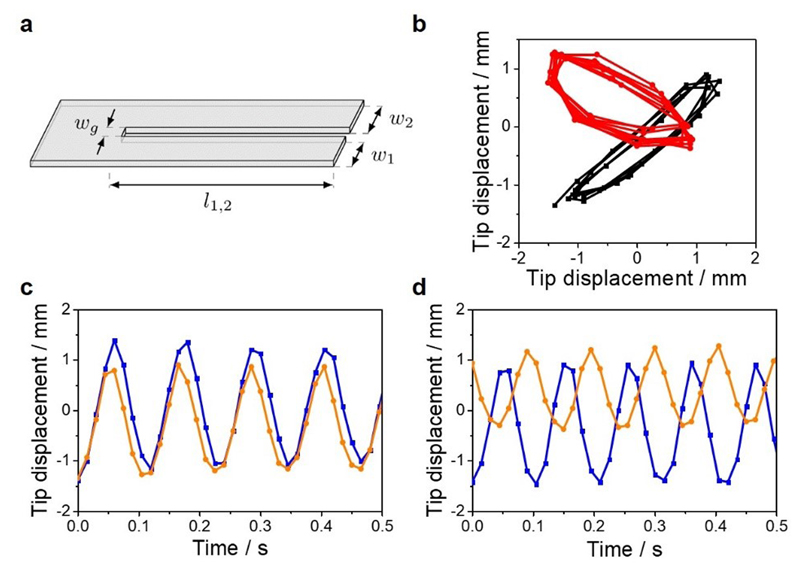
When a rectangular piece of an LCN film is slit down in the middle, creating two strip-like oscillators connected by a joint of the same material (Fig. 1a), the two oscillators show synchronized motion upon light irradiation (LED 365 nm, 0.5 W.cm-2). The oscillators move with the same period and amplitude at the same time, their motion is coupled in-phase (Fig. 1c, Supplementary Video 1). The frequency of the oscillation is 8.5 Hz ± 0.5 Hz and the amplitude, defined as the displacement of the tip, reaches about 20° in total (± 10°). The experiment is repeated several times and steady state oscillations in-phase and sometimes anti-phase are observed when using the same material (Fig. 1c,d, Supplementary Video 2). For the anti-phase synchronization, the frequency of the oscillation is 9.5 Hz ± 0.5 Hz. Similarly to the Huygens experiments on pendulum clocks,13,14 the frequency of the in-phase oscillation is close to the frequency of a single oscillator of the same dimensions (about 8.5 Hz) and the frequency of anti-phase oscillation is slightly higher (9.5 Hz) due to the active participation of the coupling joint in the anti-phase synchronization. The phase diagrams of the oscillators represent an ellipse centered on the diagonal and the counter-diagonal, typical of in-phase and anti-phase harmonic oscillators, respectively (Fig. 1b). The difference of amplitudes between the two oscillators, as visible in Fig. 1c,d, may be related to differences in the light intensity reaching the hinge of each oscillator. Indeed, it was reported previously that the light intensity affects the amplitude but not the frequency of the oscillation.27 The obtention of in-phase or anti-phase oscillations comes from environmental changes such as variation of temperature at the hinge controlled by the light position and the light intensity, or variation of the initial positions of the two synchronized oscillators. These results have been confirmed by the computer simulations presented below.
Fig. 1. Synchronized light-induced oscillation of coupled LCN films.
a, Schematic representation of the oscillators with their dimensions. The films geometry is 15 mm (l1,2) × 4 mm (w1 = w2). They are connectively separated by 2 mm (wg). The sample thickness is 20 μm. b, Phase diagrams of the in-phase (black trace) and anti-phase (red trace) oscillators. c,d, Displacement of the oscillators tips over time in the z-direction showing in-phase oscillation (c) and anti-phase oscillation (d). The displacement of one oscillator is represented with the orange trace and the other one with the blue trace.
Control experiments
Control experiments were performed to understand the origin of the coupling (Supplementary Video 3). When the light beam is focused exclusively on one strip, only the irradiated strip oscillates, and the other strip does not move. Likewise, when a strip consisting of the same material but polymerized in its isotropic state is joined to an oriented strip, upon irradiation, the oriented strip oscillates while the strip without molecular orientation stays in rest position and does not move. Moreover, when the common part of the LCN at the hinge is cut to obtain two independent strips, and the strips are clamped to two different tweezers and brought close together (about 2 mm), the oscillations are non-synchronized (neither in-phase nor anti-phase) indicating that the coupling is not derived from air dynamics. When the joint strips are clamped with a rigid pair of tweezers directly to the coupling element, resulting in a rigid joint giving a weak coupling, also no synchronization was observed. In addition to the presence of the coupling element, the influence of the width of the slit (wg) has been studied. The synchronization was observed with wg as small as possible within the conditions of the experiments (wg = 2 mm). Having wg smaller than 2 mm resulted in the two strips touching each other and disturbing the motion. Increasing wg to 10 mm resulted in non-synchronized oscillations, showing that the coupling is dependent on wg. These results indicate that the coupling strength decreases with the distance between the oscillators and confirm that the coupling occurs through the common LCN piece of film at the hinge. Overall, these control experiments stress an important prerequisite for synchronization; the two strips must be able to oscillate independently. Entrainment was not observed between one light-responsive strip capable to oscillate and one non light-responsive. It seems the coupling strength is not strong enough to trigger the oscillation of another strip.
Temperature variation during the motion
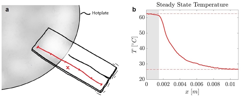
Temperature is an important parameter in the mechanism of oscillation of these LCNs27 and it was recorded during the motion. As reported for the single oscillator,27 thermal oscillations were observed on the two strips. The in-phase mechanical oscillation gave in-phase thermal oscillation whereas the anti-phase mechanical oscillation gave anti-phase thermal oscillation (Extended Data Fig. 1). Possible thermal coupling was considered but the thermal conductivity of the LCN is poor (Extended Data Fig. 2) and the thermal oscillations are precisely localized on each strip. It was therefore concluded that the two hinge sections do not significantly influence the temperatures of one another. One may note that the hinge is also irradiated and heated up in the steady state of synchronized oscillations (Extended Data Fig. 1c).
Synchronized motion of asymmetric oscillators
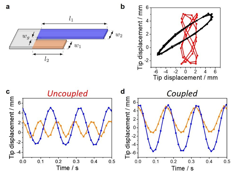
The dynamics of the system were also studied with asymmetric oscillators of unequal lengths (Fig. 1a). We reported previously that the frequency of the oscillations depends on the length of the oscillators.28 An oscillator of 18 mm long oscillates at about 5.5 Hz ± 0.5 Hz (Fig. 2c blue trace, Supplementary Video 4), and shortening the film to reach 12 mm gives oscillation at about 10.1 Hz ± 0.5 Hz (Fig. 2c orange trace, Supplementary Video 5). When these two oscillators with lengths of 18 mm and 12 mm respectively, are coupled, they oscillate at the same frequency of 6.2 Hz ± 0.5 Hz (Fig. 2d, Supplementary Video 6). The phase diagrams in Fig. 2b capture the difference between the coupled and non-coupled asymmetric oscillators with the coupled oscillators giving an ellipse centered on the diagonal. These results demonstrate that one oscillating strip can entrain31 a shorter strip to oscillate slower than its natural frequency. The long oscillator moves at about the same frequency when coupled or uncoupled. This experiment also shows the robustness of the coupling mechanism, resistant to variations in the oscillators’ length. Next to variation of the length, the frequency of the oscillations was found to be independent of the width of the oscillators, in correspondence to the theory around the natural frequency,27 making an exact adjustment of w1 = w2 unnecessary. Moreover, strips thicker than 20 μm and wider than 5 mm do not oscillate because of their increased stiffness, which considerably limits the possibility to explore synchronization between asymmetric strips of unequal widths and thicknesses.
Fig. 2. Entrainment of asymmetric oscillators.
a, Schematic representation of the asymmetric films. The films geometry is 18 mm (l1, in blue) × 12 mm (l2, in orange) × 4 mm (w1 = w2) × 2 mm (wg) x 20 μm (th). b, Phase diagrams of the uncoupled (red trace) and coupled (black trace) oscillators. c, Oscillation of the decoupled short and long oscillators. d, Oscillation of the coupled long and short oscillators. The displacement of the short oscillator is represented with the orange traces, and the long oscillator with the blue traces.
Modeling of the synchronized motion
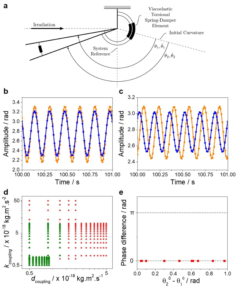
To gain insights into the mechanism of this synchronization and its origin, we carried out modeling of the coupled oscillators. The thin film is modeled as a standard spring-damper mechanical oscillator and the equation of motion is derived from the Euler-Lagrange method (Fig. 3a, see Methods).32 The body of the film is represented by a rigid thin plate. The elements that contribute to the dynamic property in the model include an actuation torque and a viscoelastic torsional spring-damper element in the hinge. The spring-damper element is defined by a stiffness parameter (k(T) = α.E’(T), with E’ the storage modulus of the LCN film) and a damping parameter (d(T) = β.E”(T), with E” the loss modulus of the LCN film). The stiffness and damping parameters depend on the temperature and their equations were derived from experimental mechanical tests where we took the temperatures as measured by the infrared camera as input (Extended Data Fig. 3). Eventual photo-softening effects are ignored as thermal cycling takes place well above the glass transition temperature where the moduli are less temperature sensitive.33 The actuation is modeled as torque at the hinge and determined by the temperature dynamics of the LCN film (Extended Data Figs. 4-5). As evident from the overlap between the experimental and calculated oscillations obtained (Extended Data Fig. 6), this model sufficiently describes the system with the stiffness and damping parameters reported in Supplementary Table 1. To proceed with the coupled oscillators, a coupling element was incorporated in the form of a torsional spring-damper element located in the hinge between the two oscillators. This coupling element is also characterized by a stiffness parameter k coupling and a damping parameter d coupling (see Methods). The initial positions for the simulations, i.e. angles, angular velocities and temperatures are set to be either randomized or fixed between the boundaries of the oscillation space.
Fig. 3. Modeling of the coupled oscillators.
a, Schematic representation of the forced, damped coupled oscillator model. b, Simulation showing in-phase oscillations. c, Simulations showing anti-phase oscillations. The simulations are given in the steady states. d, Phase diagram with the coupling stiffness parameter k coupling versus the coupling damping parameter d coupling. The data points giving in-phase oscillation are represented by red stars and the ones giving unstable state by green triangles. e, Phase difference between the coupled oscillations as a function of the difference in the initial positions of the two oscillators.
The results of the simulations demonstrate good qualitative agreement with the experiments. The two oscillators synchronize their motion into two steady eigenmodes of the system: in-phase and anti-phase oscillations (Fig. 3b,c). The in-phase synchronization is more easily achieved than the anti-phase oscillation, indicating a difference in robustness and/or the corresponding basins of attraction between the two steady modes. The anti-phase simulated oscillation observed experimentally is also obtained in the simulated model although less perfectly. We investigated the influence of three parameters on the states of synchrony: the starting positions of the oscillators, the coupling stiffness parameter and the coupling damping parameter. A phase diagram was obtained by varying the coupling stiffness and damping parameters for fixed in-phase and anti-phase starting positions of θ1 0 = θ2 0 and θ1 0 = - θ2 0, respectively (Fig. 3d). We could show that depending on the strength of the coupling, the solutions are stable or unstable in the sense of Lyapunov, i.e. the solutions initiated close enough to each other remain close enough forever (stable states) or diverge (unstable states). For strong coupling, the model gives stable states with the solutions being always in-phase oscillation. These stable states are tolerant to changes in initial positions (Fig. 3e). Indeed, by varying the initial positions of the two oscillators, the model shows that the final state in-phase synchronization does not change. Even when the two oscillators start in anti-phase positions, they converge into in-phase synchrony showing that the convergence of the in-phase mode is independent on the initial positions. However, for weak coupling, the model gives unstable states that switch between steady in phase or anti-phase synchrony depending on the initial positions for the same coupling parameters (Extended Data Figs 7 and 8). In other words, for weak coupling, small perturbations of the initial positions of the oscillators bring the system to different steady solutions (in-phase and anti-phase). Experimentally, this instability is visible when synchrony in-phase and anti-phase are observed with the same material. It did not escape our attention that occasionally, even more complex coupling modes can be observed (Extended Data Fig. 9, Supplementary Video 7). Altogether, these results show that slight variations of coupling stiffness, coupling damping and starting positions can change the mode of synchrony between in-phase and anti-phase motion and confirm the experimental observations. Such variation of stiffness, damping and starting positions in the system could emerge from environmental changes such as temperature fluctuations at the hinge originating from changes in light position and light intensity, and dynamics effects.
Outlook
In conclusion, we discovered that two joint liquid crystal network oscillators, driven by light, communicate together and synchronize their oscillations, as Huygens observed with pendulum clocks.12,13 The synchronization originates from a mechanical coupling in the joint of the oscillators and is sensitive to changes in the stiffness and the damping of the joint. Therefore, such a system could be used as sensors of the mechanical properties of materials. Synchronization and collective motion are a fascinating expression of self-organization that nature uses to sustain life. Mimicking such properties into life-like materials is a challenge undertaken at all length scales, from the nanoscopic34–37 to the macroscopic scales. This work participates in these on-going efforts to translate molecular events into macroscopic effects and proposes a general approach to create collective motion into polymeric materials. It is foreseen that these results can be of great value in the fascinating developments in soft robotics.
Methods
Materials and Fabrication of the films
We prepare LCNs by the photo-polymerization of a mixture of commercially available mesogens RM82 (60 wt%) and RM23 (37.5 wt%), the photo-active component (hydroxyphenyl)benzotriazole (Tinuvin 328, 2.5 wt%, Extended Data Fig. 10) and a photo-initiator (Irgacure 819, <1 wt%). The chemicals were obtained from Merck. The method to prepare thin films has been precisely reported elsewhere.38 Prior to polymerization, the mesogens are aligned in splay fashion by the use of polyimide alignment layers in custom-made cells. The splay alignment consists of a planar alignment on one side of the film, and a homeotropic alignment on the other side, with a gradual change in the molecular orientation over the 20 μm thickness of the film. The glass transition temperature of the film is about 45°C. The moduli are reported in Extended Data Fig. 3. For the control experiment where a strip consisting of the same material but polymerized in its isotropic state is joined to an oriented strip, photo-polymerization by a mask exposure is performed. First, the mixture is photo-polymerized through a mask at 70°C (LC phase) for 5s. Then the mask is removed, the temperature is increased to 110°C (isotropic phase), and the photo-polymerization is completed on the entire substrate.
Photo-actuation
The films were peeled off from the glass substrate of the cell and cut using a razor blade into two long strips connected by a joint of the same material (Fig. 1a), with the alignment director of the mesogens parallel to the long edge. The two parallel strips are clamped by the hinge, with the side of planar molecular alignment facing the lamp and simultaneously irradiated with an LED mounted with a collimator (Thorlabs) emitting 365 nm (0.5 W.cm-2). Upon irradiation, the films bend toward the light and after a few seconds, the two films show a steady self-oscillation.
Characterization of the films and the motion
The temperature of the films was reported with a high-speed thermal camera Gobi from Xenics. The videos of the oscillations were recorded by a PCO 5.5 sCMOS camera and the recordings were further treated with software of image analysis.
The moduli of the films were determined using a Q800 machine by TA Instruments.
Modeling of the motion derived from the Euler-Lagrange method
First, we derive the equations of motion for the single LCN oscillator. This model will be extended later on toward the case of double oscillators. Let θ IC stand for the angle of the free oscillator which corresponds to the steady state equilibrium of the irradiated film. Let T stand for the temperature of the hinge. The kinetic energy of the film is defined as
| (1) |
where J is the corresponding inertia moment. The potential energy is defined then as
| (2) |
where g is the acceleration due to gravity, m is the mass of the film, l is the length of the film and k is the stiffness of the torsion spring.
Subsequently, the Lagrangian of the system is constructed as
| (3) |
and the Euler-Lagrange equations
| (4) |
have the following form
| (5) |
Here the non-conservative terms are given by
| (6) |
with d being the damping factor and u is the temperature dependent torque at the hinge.
In a similar fashion one can derive a dynamical model for two coupled LCN films. We assume that the films are coupled via a torsion spring and damper, a mechanically more advanced flexible coupling previously reported.32 In other words, there is an extra potential energy associated with the angular difference of two oscillators:
| (7) |
With this assumption the model of coupled identical oscillators is given by the following two second order differential equations:
| (8) |
| (9) |
The inertia moment of the oscillators J is calculated under the assumption that each film is a rigid lamina:
| (10,11) |
where ρ is the film density and h,w are the height and the width of the film respectively (see Supplementary Table 1).
The stiffness and damping of the spring-damper elements of the model are designed to be proportional to the storage and loss moduli of the LCN, respectively.
The stiffness and damping coefficients k and d of the spring-damper elements are defined as:
| (12) |
and
| (13) |
respectively (see Extended Data Fig.3), where α is the stiffness scaling parameter and β is the damping scaling parameter (see Supplementary Table 1).
The torque u i, i=1,2 generated by the hinge heating is modeled as a linear function of the hinge temperature:
| (14) |
here v is the scaling parameter, T amb, T max are the ambient and maximal temperatures respectively (see Supplementary Table 1).
The hinge temperature for each oscillator is modeled as the following first order differential equation
| (15) |
where the functions λ(T) and Δ(T) are defined as
| (16,17) |
with tuning parameters τ a, τ d determined experimentally as τ a = 0.75 s, τ d = 0.64 s (see Extended Data Fig. 5).
During the simulation, the values of the oscillator's geometrical properties, including length, width, density and thickness are slightly randomized by ±1% of its default. The randomization eliminates identicality and causes the system to rely on synchronization induced by its mechanical coupling.
Extended Data
Extended Data Fig. 1. Thermal oscillation.
a,b, Temperature of the coupled LCN films during in-phase oscillation (a) and anti-phase oscillation (b). c, Picture of the thermogram with the two points A and B where the temperatures are measured. The temperature at point A is the blue trace and at point B is the orange trace. The films geometry is 20 mm × 4 mm × 20 μm and are connectively separated by 2 mm.
Extended Data Fig. 2. Thermal conductivity.
a, Scheme of the LCN film positioned on a hot plate at 63°C. b, Temperature profile over the length of the film showing the poor thermal conductivity of the LCN.
Extended Data Fig. 3. Modeling of the stiffness and damping parameters.
Tensile moduli of the LCN film as a function of temperature (red traces) and their modeled fits (black traces).
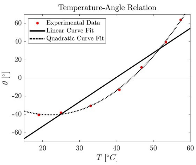
Extended Data Fig. 4. Modeling of the actuation torque with temperature.
Displacement of the film tip over temperature (dotted line) and the linear fit obtained (black trace).
Extended Data Fig. 5. Modeling of the temperature dynamics.
Temperature of the LCN film upon switching the LED on (left) and off (right). The experimental data are the red traces and the calculated fits are the black traces.
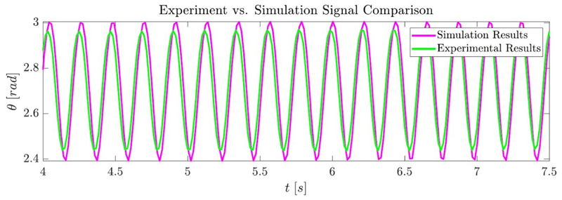
Extended Data Fig. 6. Comparison of the experimental and calculated oscillations.
Experimental (green trace) and simulation (magenta trace) results of the oscillation over time.
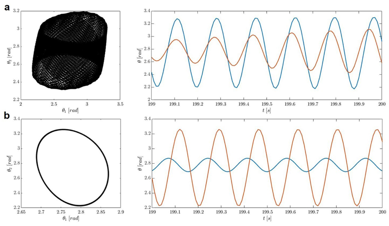
Extended Data Fig. 7. Modeling with a weak coupling showing changes in the final state depending on the starting conditions.
a, Example of non-periodic oscillations modeled with the coupling stiffness parameter k coupling = 5 x 10-19 kg.m2.s-2 and the coupling damping parameter d coupling. = 7.29 x 10⁻¹⁹ kg.m2.s-1, with the starting conditions θ1 0 = θ2 0 = 2.3 rad showing instability and b, with the starting conditions θ1 0 = 2.6 rad and θ2 0 = 3.3 rad showing anti-phase oscillation.
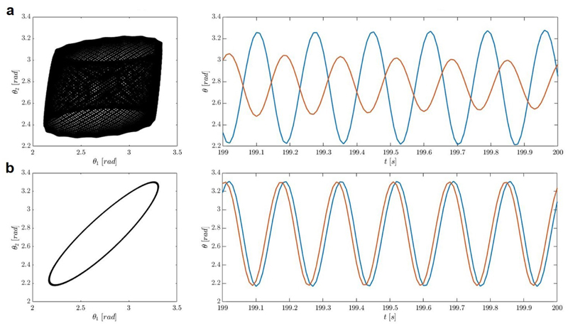
Extended Data Fig. 8. Modeling with a weak coupling showing changes in the final state depending on the starting conditions.
a, Example of non-periodic oscillations modeled with the coupling stiffness parameter k coupling = 5 x 10-19 kg.m2.s-2 and the coupling damping parameter d coupling. = 7.29 x 10⁻¹⁹ kg.m2.s-1, with the starting conditions θ1 0 = 3.1 rad and θ2 0 = 2.3 rad showing non-periodic oscillations and b, with the starting conditions θ1 0 = 2.9 rad and θ2 0 = 2.6 rad showing in-phase oscillation.
Extended Data Fig. 9. Complex synchronized motion of coupled LCN experimentally obtained.
a, Displacement of the tips of the two coupled oscillators over time in the z-direction. The displacement of one oscillator is represented with the orange trace and the other one with the blue trace. b, A different motion obtained stochastically after switching the LED on and off. The data reported in graphs a and b are plotted from two different sequences combined in Supplementary Video 7. The data plotted on graph a are from the first minute of Supplementary Video 7, and the data on the graph b are from the second sequence of Supplementary Video 7.
Extended Data Fig. 10. Chemical structures of the molecules used.
Supplementary Material
Acknowledgments
This work was financially supported by The Netherlands Organization for Scientific Research (NWO-TOP PUNT Grant 10018944, NWO-VENI Grant 722.017.003), Dutch Ministry of Education, Culture and Science (Gravity Program 024.001.035) and the European Research Council (Vibrate ERC, Grant 669991).
Footnotes
Contributions
G.V., E.W.M. and D.J. B. conceived and planned the project. G.V. and A.H.G. performed the experiments. L.C.M.E. performed the simulations. D.J.B., H.N., A.Y.P. and E.W.M. supervised the effort. G.V. wrote the manuscript. All authors discussed the results and commented on the manuscript.
Competing Interests
The authors declare no competing interests.
Contributor Information
Ghislaine Vantomme, Institute for Complex Molecular Systems, Eindhoven University of Technology, Eindhoven, The Netherlands; Department of Chemical Engineering and Chemistry, Laboratory of Macromolecular and Organic Chemistry, Eindhoven University of Technology, Eindhoven, The Netherlands.
Lars C. M. Elands, Department of Mechanical Engineering, Dynamics and Control, Eindhoven University of Technology, Eindhoven, The Netherlands
Anne Helene Gelebar, Institute for Complex Molecular Systems, Eindhoven University of Technology, Eindhoven, The Netherlands; Department of Chemical Engineering and Chemistry, Laboratory for Functional Organic Materials and Devices, Eindhoven University of Technology, Eindhoven, The Netherlands.
E. W. Meijer, Institute for Complex Molecular Systems, Eindhoven University of Technology, Eindhoven, The Netherlands; Department of Chemical Engineering and Chemistry, Laboratory of Macromolecular and Organic Chemistry, Eindhoven University of Technology, Eindhoven, The Netherlands
Alexander Y. Pogromsky, Department of Mechanical Engineering, Dynamics and Control, Eindhoven University of Technology, Eindhoven, The Netherlands; Department of Control Systems and Industrial Robotics, Saint-Petersburg National Research University of Information Technologies Mechanics and Optics (ITMO), Russia.
Henk Nijmeijer, Institute for Complex Molecular Systems, Eindhoven University of Technology, Eindhoven, The Netherlands; Department of Mechanical Engineering, Dynamics and Control, Eindhoven University of Technology, Eindhoven, The Netherlands.
Dirk J. Broer, Institute for Complex Molecular Systems, Eindhoven University of Technology, Eindhoven, The Netherlands; Department of Chemical Engineering and Chemistry, Laboratory for Functional Organic Materials and Devices, Eindhoven University of Technology, Eindhoven, The Netherlands
Data availability
The data that support the findings of this study are available within the article and its Supplementary Information files and from the corresponding authors upon reasonable request.
References
- 1.Whitesides GM. Soft robotics. Angew Chem Int Ed. 2018;57:4258–4273. doi: 10.1002/anie.201800907. [DOI] [PubMed] [Google Scholar]
- 2.Zhang X, et al. The pathway to intelligence: using stimuli-responsive materials as building blocks for constructing smart and functional systems. Adv Mater. 2019;31 doi: 10.1002/adma.201804540. [DOI] [PubMed] [Google Scholar]
- 3.Yu Y, Ikeda T. Soft actuators based on liquid-crystalline elastomers. Angew Chem Int Ed. 2006;45:5416–5418. doi: 10.1002/anie.200601760. [DOI] [PubMed] [Google Scholar]
- 4.Hines L, Petersen K, Lum GZ, Sitti M. Soft actuators for small-scale robotics. Adv Mater. 2017;29 doi: 10.1002/adma.201603483. 1603483. [DOI] [PubMed] [Google Scholar]
- 5.Martella D, Nocentini S, Parmeggiani C, Wiersma DS. Self-regulating capabilities in photonic robotics. Adv Mater Technol. 2019;4 1800571. [Google Scholar]
- 6.Zeng H, Wasylczyk P, Wiersma DS, Priimagi A. Light robots: bridging the gap between microrobotics and photomechanics in soft materials. Adv Mater. 2018;30 doi: 10.1002/adma.201703554. 1703554. [DOI] [PubMed] [Google Scholar]
- 7.Hu Y, Li Z, Lan T, Chen W. Photoactuators for direct optical-to-mechanical energy conversion: from nanocomponent assembly to macroscopic deformation. Adv Mater. 2016;28:10548–10556. doi: 10.1002/adma.201602685. [DOI] [PubMed] [Google Scholar]
- 8.Pikovsky A, Rosenblum M, Kurths J. Synchronization : a universal concept in nonlinear sciences. Cambridge University Press; 2001. [Google Scholar]
- 9.Vicsek T, Zafeiris A. Collective motion. Phys Rep. 2012;517:71–140. [Google Scholar]
- 10.Boccaletti S. The Synchronized Dynamics of Complex Systems. Monograph Series on Nonlinear Science and Complexity. 2008;6 [Google Scholar]
- 11.O’Keeffe KP, Hong H, Strogatz SH. Oscillators that sync and swarm. Nat Commun. 2017;8:1–13. doi: 10.1038/s41467-017-01190-3. [DOI] [PMC free article] [PubMed] [Google Scholar]
- 12.Huygens C. A. du texte. Oeuvres complètes de Christiaan Huygens. L’horloge à pendule de 1651 à 1666. Travaux divers de physique, de mécanique et de technique de 1650 à 1666. Traité des couronnes et des parhélies (1662 ou 1663) / publ. par la Société hollandaise des sciences. 1888 (1629-1695) [Google Scholar]
- 13.Bennett M, Schatz MF, Rockwood H, Wiesenfeld K. Huygens’s clocks. Proc R Soc A Math Phys Eng Sci. 2002;458:563–579. [Google Scholar]
- 14.Peña Ramirez J, Olvera LA, Nijmeijer H, Alvarez J. The sympathy of two pendulum clocks: Beyond Huygens’ observations. Sci Rep. 2016;6:1–16. doi: 10.1038/srep23580. [DOI] [PMC free article] [PubMed] [Google Scholar]
- 15.Ikeguchi T, Shimada Y. Understanding Complex Systems. Springer Verlag; 2019. Analysis of synchronization of mechanical metronomes; pp. 141–152. [Google Scholar]
- 16.Rubenstein M, et al. Programmable self-assembly in a thousand-robot swarm. Science. 2014;345(6198):795–799. doi: 10.1126/science.1254295. [DOI] [PubMed] [Google Scholar]
- 17.Li S, et al. Particle robotics based on statistical mechanics of loosely coupled components. Nature. 2019;567:361–365. doi: 10.1038/s41586-019-1022-9. [DOI] [PubMed] [Google Scholar]
- 18.Justus KB, et al. A biosensing soft robot: autonomous parsing of chemical signals through integrated organic and inorganic interfaces. Sci Robot. 2019;4:eaax0765. doi: 10.1126/scirobotics.aax0765. [DOI] [PubMed] [Google Scholar]
- 19.Ciui B, et al. Chemical sensing at the robot fingertips: toward automated taste discrimination in food samples. ACS Sens. 2018;3(11):2375–2384. doi: 10.1021/acssensors.8b00778. [DOI] [PubMed] [Google Scholar]
- 20.Korevaar PA, et al. Non-equilibrium signal integration in hydrogels. Nat Commun. 2020;11 doi: 10.1038/s41467-019-14114-0. 386. [DOI] [PMC free article] [PubMed] [Google Scholar]
- 21.Martella D, et al. Photonic microhand with autonomous action. Adv Mater. 2017;29 doi: 10.1002/adma.201704047. 1704047. [DOI] [PubMed] [Google Scholar]
- 22.Wani O, et al. A light-driven artificial flytrap. Nat Commun. 2017;8 doi: 10.1038/ncomms15546. 15546. [DOI] [PMC free article] [PubMed] [Google Scholar]
- 23.Byun J, et al. Electronic skins for soft, compact, reversible assembly of wirelessly activated fully soft robots. Sci Robot. 2018;3:eaas9020. doi: 10.1126/scirobotics.aas9020. [DOI] [PubMed] [Google Scholar]
- 24.Yang JC, et al. Electronic skin: recent progress and future prospects for skin-attachable devices for health monitoring, robotics, and prosthetics. Adv Mater. 2019 doi: 10.1002/adma.201904765. 1904765. [DOI] [PubMed] [Google Scholar]
- 25.Zhang M, et al. Synchronization of micromechanical oscillators using light. Phys Rev Lett. 2012;109:1–5. doi: 10.1103/PhysRevLett.109.233906. [DOI] [PubMed] [Google Scholar]
- 26.White TJ, Broer DJ. Programmable and adaptive mechanics with liquid crystal polymer networks and elastomers. Nat Mater. 2015;14:1087–1098. doi: 10.1038/nmat4433. [DOI] [PubMed] [Google Scholar]
- 27.Gelebart AH, Vantomme G, Meijer EW, Broer DJ. Mastering the photothermal effect in liquid crystal networks: a general approach for self-sustained mechanical oscillators. Adv Mater. 2017;29 doi: 10.1002/adma.201606712. 1606712. [DOI] [PubMed] [Google Scholar]
- 28.Vantomme G, Gelebart AH, Broer DJ, Meijer EW. Self-sustained actuation from heat dissipation in liquid crystal polymer networks. J Polym Sci Part A Polym Chem. 2018;56:1331–1336. doi: 10.1002/pola.29032. [DOI] [PMC free article] [PubMed] [Google Scholar]
- 29.White TJ, et al. A high frequency photodriven polymer oscillator. Soft Matter. 2008;4:1796–1798. [Google Scholar]
- 30.Vantomme G, Gelebart AH, Broer DJ, Meijer EW. A four-blade light-driven plastic mill based on hydrazone liquid-crystal networks. Tetrahedron. 2017;73:4963–4967. [Google Scholar]
- 31.Cafferty BJ, et al. Robustness, entrainment, and hybridization in dissipative molecular networks, and the origin of life. J Am Chem Soc. 2019;141:8289–8295. doi: 10.1021/jacs.9b02554. [DOI] [PubMed] [Google Scholar]
- 32.Peña Ramirez J, Fey RHB, Aihara K, Nijmeijer H. An improved model for the classical Huygens’ experiment on synchronization of pendulum clocks. J Sound Vib. 2014;333:7248–7266. [Google Scholar]
- 33.Shimamura A, et al. Simultaneous analysis of optical and mechanical properties of cross-linked azobenzene-containing liquid-crystalline polymer films. ACS Appl Mater Interfaces. 2011;3:4190–4196. doi: 10.1021/am200621j. [DOI] [PubMed] [Google Scholar]
- 34.Merindol R, Walther A. Materials learning from life: Concepts for active, adaptive and autonomous molecular systems. Chem Soc Rev. 2017;46:5588–5619. doi: 10.1039/c6cs00738d. [DOI] [PubMed] [Google Scholar]
- 35.Dattler D, et al. Design of collective motions from synthetic molecular switches, rotors, and motors. Chem Rev. 2020;120:310–433. doi: 10.1021/acs.chemrev.9b00288. [DOI] [PubMed] [Google Scholar]
- 36.Leira-Iglesias J, Tassoni A, Adachi T, Stich M, Hermans TM. Oscillations, travelling fronts and patterns in a supramolecular system. Nat Nanotechnol. 2018;13:1021–1027. doi: 10.1038/s41565-018-0270-4. [DOI] [PubMed] [Google Scholar]
- 37.Boekhoven J, Hendriksen WE, Koper GJM, Eelkema R, Van Esch JH. Transient assembly of active materials fueled by a chemical reaction. Science. 2015;349:1075–1079. doi: 10.1126/science.aac6103. [DOI] [PubMed] [Google Scholar]
- 38.Vantomme G, Gelebart AH, Broer DJ, Meijer EW. Preparation of liquid crystal networks for macroscopic oscillatory motion induced by light. J Vis Exp. 2017 doi: 10.3791/56266. [DOI] [PMC free article] [PubMed] [Google Scholar]
Associated Data
This section collects any data citations, data availability statements, or supplementary materials included in this article.
Supplementary Materials
Data Availability Statement
The data that support the findings of this study are available within the article and its Supplementary Information files and from the corresponding authors upon reasonable request.


