Abstract
Optoelectronic systems can exert precise control over targeted neurons and pathways throughout the brain in untethered animals, but similar technologies for the spinal cord are not well established. Here, we describe a novel system for ultrafast, wireless, closed-loop manipulation of targeted neurons and pathways across the entire dorsoventral spinal cord in untethered mice. We developed a soft stretchable carrier integrating micro-LEDs that conforms to the dura matter of the spinal cord. A coating of silicone-phosphor matrix over the micro-LEDs provides mechanical protection and light conversion for compatibility with the large library of opsins. A lightweight, head-mounted wireless platform powers the micro-LEDs and performs low-latency on-chip processing of sensed physiological signals to control photostimulation in a closed-loop. We use the device to reveal the role of various neuronal subtypes, sensory pathways and supraspinal projections in the control of locomotion in healthy and spinal-cord injured mice.
Optogenetics has opened up unprecedented possibilities for controlling targeted cells and pathways of the nervous system with high spatiotemporal precision 1–3 . The ability to dissect and manipulate the mechanisms underlying brain functions in health and disease has triggered the development of myriad systems to deliver photostimulation to peripheral nerves and in the brain 4–12 .
The spinal cord is essential to the control of movement and many basic physiological functions. Unraveling the role of neurons and pathways embedded in the spinal cord is therefore a major endeavor in basic and clinical neuroscience. Compared to the brain, the spinal cord combines a series of unique challenges that require novel light-delivery technologies 6,10,13–19 . During natural behaviors, the spinal cord undergoes extensive displacements that are incompatible with penetrating optic fibers 20 . Consequently, the light must be delivered from sources positioned over the surface of the dura mater 21 . Since the light rapidly scatters when penetrating spinal tissues, targeting deep intraspinal neurons with epidural light-emitting sources requires irradiances that are substantially higher than those required for photostimulation in the vicinity of targeted neurons or pathways. Such high-intensity illumination poses both technological and physiological challenges. Technologically, substantial irradiances require stable current flows delivered to the optoelectronic device despite miniaturized metallic structures and movement-related mechanical stress. Physiologically, high irradiance leads to local heating of tissue due to light absorption, which may alter neuronal responses 22 . Moreover, avoidance of tissue damage while ensuring efficient photostimulation requires embedding light-emitting sources within protective substrates that must conform to the topology, compliance, and dynamics of spinal tissues. The poor accessibility and limited anchoring options of the vertebral column and spinal cord add a layer of complexity to the resolution of all these features 6,13,14 . Indeed, spinal cord implants are prone to mechanical failure and poor biointegration 18 .
Here, we engineered a wireless optoelectronic system that possesses all the desired features for safe and long-term photostimulation of any targeted neurons and pathways in untethered and unrestricted mice. Moreover, we endowed the electronics with data acquisition and on-chip data processing capabilities that enabled ultrafast closed-loop control of photostimulation using real-time processing of physiological signals.
Results
Topological and mechanical requirements for spinal implants
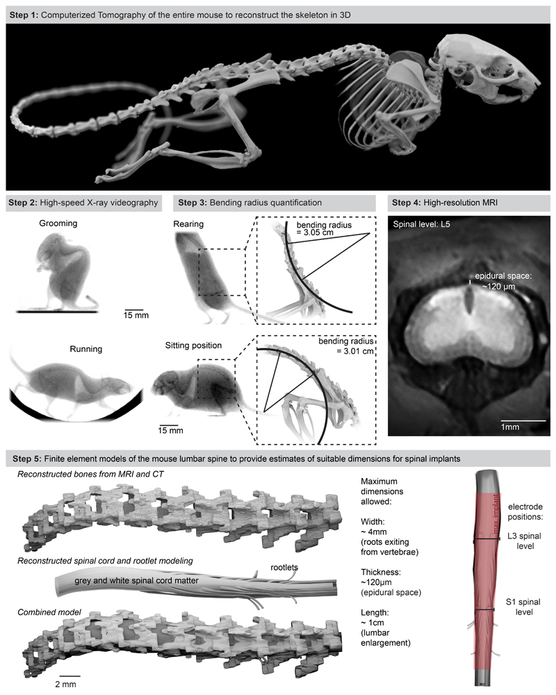
We first collected the topological and mechanical requirements to ensure the long-lasting and safe integration of an optoelectronic implant over the entire extent of the mouse lumbar spinal cord. We acquired high-resolution magnetic resonance imaging (MRI) and computerized tomography (CT) datasets to generate a tridimensional anatomical model of the mouse spinal cord and vertebral column (Extended Data Fig. 1, Supplementary Video 1). We performed high-speed X-ray imaging (196 Hz) of freely behaving mice to capture the posture during standing, grooming and walking. We morphed the anatomical model onto these postures to quantify lumbar spine curvatures underlying ecological behaviors of mice (minimum bending radius of the spine, 5.13 cm; Extended Data Fig. 1, Supplementary Video 1). These analyses outlined the suitable length (18 mm), width (2.5 mm) and thickness (< 100 μm) of the implant to cover the rostrocaudal and mediolateral extents of the lumbar spinal cord, while providing quantified metrics on the required stretchability and conformability.
Design of the soft optoelectronic implant
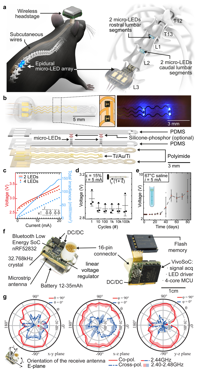
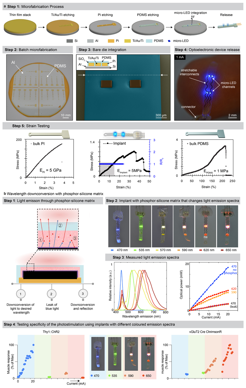
We aimed to design an optoelectronic implant that is resilient to the demands of chronic implantation in the epidural space of mice, yet conformable to the curvilinear morphology of the soft spinal cord (Fig. 1a). To resolve this challenge, we combined thin-film microtechnology, elasticity engineering, microscale light emitting diodes (micro-LED), and dura-like silicone (Fig. 1b, Supplementary Video 1). We selected blue and green (λ = 470 nm, λ = 535 nm) LED in a bare die format of small dimensions (270 x 220 x 50 μm3) that we interfaced with elastic serpentine Ti/Au/Ti (titanium/gold/titanium) interconnects embedded in polyimide film (Extended Data Fig. 2a). Each micro-LED was then coated with a silicone-phosphor composite 23 , before encapsulation of the entire array within a silicone membrane that matched the mechanical compliance of the natural dura mater 24 . This soft optoelectronic implant accommodates elongations (15% strain) that exceeded the physiological range of lumbar spinal cord displacements 18 . Reliable electrical properties for at least 30 days in accelerated ageing conditions suggested that the optoelectronics would survive several weeks in vivo (Fig. 1d, e, Extended Data Fig. 2, Step 5).
Fig. 1. Wireless optoelectronic system for closed-loop photostimulation of the lumbar spinal cord.
a, Schematic overview of optoelectronic system, including a zoom on the insertion of the micro-LED array over the epidural surface of the spinal cord.
b, Photographs of the micro-LED array, including a zoom on the micro-LEDs, and exploded diagram of the array.
c, Optoelectronic characterization under incremental bias (λ = 470 nm).
d, Stretchability. The optoelectronic implant was cycled at 15% strain, which corresponds to the range of motion of the lumbar spinal cord, for 100’000 cycles while continuously emitting light (n = 3, mean±s.e.m.).
e, Accelerated aging. The optoelectronic implant was immersed in 67°C saline to accelerate degradation. The devices start failing around 40 days (n = 4, mean±s.e.m.).
f, Photographs of the electronics embedded in the wireless, head-mounted platform that records physiological signals and power the optoelectronics.
g, In-air antenna radiation characteristics, measured in an anechoic chamber with a battery-operated software-modified version of the headstage wireless device (emitting a carrier) and a linearly polarized receive antenna. Drawn lines represent measurements at centre frequency (2440MHz) while the shades cover the full Bluetooth Low Energy bandwidth based on additional measurements at 2400MHz, 2420MHz, and 2480MHz.
Electronics for recording and photostimulation
When conceiving the electronics to power the micro-LEDs and collect physiological signals, we intended to develop a wearable solution enabling the use of the same electronics in multiple mice and experiments.
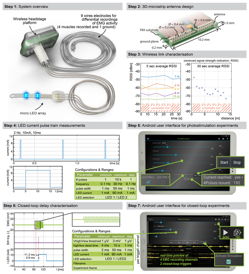
We thus developed an ultraminiaturized, battery powered, wearable, wireless recording and stimulation platform (1.1g, 0.5cm3) that can be easily plugged onto a head-mounted connector interfaced with the micro-LED array. The platform was designed based on a custom integrated circuit system-on-chip for biomedical telemetry applications, termed VivoSoC3 25 (Fig. 1f and Extended Data Fig. 3). The platform enables precise pulsed current control of 2 LED channels and recording from 4 pairs of electrodes. VivoSoC3 features a quad-core microcontroller unit for low-latency on-chip signal processing, which enables automated delivery of photostimulation based on acquired signals from physiological sensors. A 256MB flash chip stores the acquired raw data and stimulation logs for offline analyses. The current delivered to each micro-LED can be configured independently over a broad range of amplitudes (1-60mA), frequencies (0.1-100Hz), pulse widths (1-50ms) and pulse repetitions (1-10,000) with fine resolution (1 mA, 0.1 Hz, 1 ms, 1). Bluetooth communication enables fast, bidirectional and programmable control of each LED channel over distances exceeding 5 meters in standard laboratory settings (Extended Data Fig. 3, Step 3). The platform is operated via a handheld tablet that displays a real-time preview of the acquired physiological signals, the timing of the photostimulation, and a feedback on the accurate delivery of the configured current. The rechargeable battery of the detachable platform lasts for up to 11 hours, including when data are streamed to the tablet in real-time via Bluetooth while photostimulation is controlled in closed-loop. In-between experiments, the platform is plugged onto a USB-powered station to be recharged.
Chronic biointegration of the soft optoelectronic implant
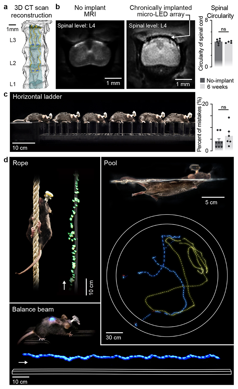
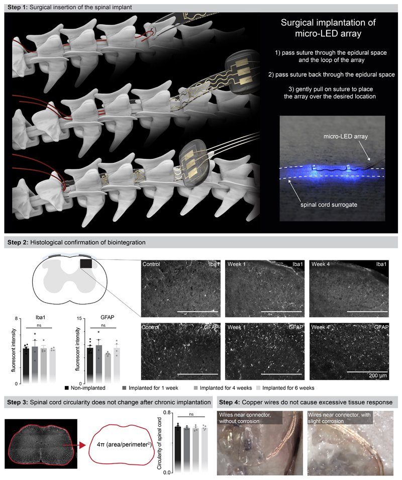
We next evaluated whether the mechanical properties of the micro-LED array met the static and dynamic requirements for long-term implantation in adult mice. The tailored dimensions of the implant (width: 2.5 mm; length: 1.8 cm; height: 100 μm) allowed smooth surgical insertion between the vertebra and spinal cord (width: 4 mm; height: 0.12 mm) using a small laminotomy, i.e. with minimal opening of the intervertebral/interlaminar space and without permanent attachment to the vertebrae (Extended Data Fig. 4, Supplementary Video 1). CT reconstructions and MRI illustrated the conformability of the implant over the curved surface of the lumbar spinal cord (Fig. 2a,b). Quantification of foreign body responses based on the levels of glial fibrillary acidic protein (GFAP) and ionized calcium binding adaptor molecule 1 (Iba1) 20 confirmed the seamless biointegration of the micro-LED array within the spine for up to 6 weeks (Extended Data Fig. 4).
Fig. 2. Long-term biointegration and photostimulation in ecological environments.
a, 3D rendering of the vertebra T13-L3 and micro-LED array reconstructed from high-resolution CT scans
b, MRI of a spinal cord without and with an implanted micro-LED array. The bar graph reports the mean circularity of the spinal cord (n=4-6 mice, two-sided unpaired t-test, p = 0.67, mean±s.e.m.).
c, Chronophotography of a mouse walking freely and with precise paw placement along a horizontal ladder, despite the implanted micro-LED array and wearable platform. The bar plot reports quantification of the percentage of foot falls (n=6-8 mice, two-sided unpaired t-test, p = 0.57, mean±s.e.m.).
d, Chronophotography of mice performing classical behavioural paradigms in ecological environments while receiving continuous photostimulation of the lumbar spinal cord. The paradigms include climbing up a rope, swimming in a large tank of water, and narrow beam walking.
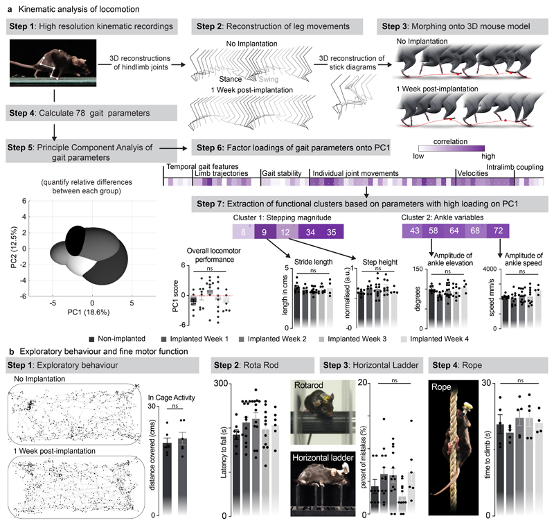
We then conducted a battery of tests to ask whether the spinal implant altered the natural behavior of the mice. We quantified locomotor performances using longitudinal recordings of whole-body kinematics during running and skilled locomotion. Quantification of these high-precision recordings using sensitive multifactorial statistical analyses 26 revealed no measurable changes in gait patterns and balance performance (n = 6, Fig. 2c and Extended Data Fig. 5). Moreover, the micro-LED array had no impact on exploratory behaviors measured in an open field (Extended Data Fig. 5).
Long-term photostimulation in ecological environments
This optoelectronic system enabled real-time photostimulation of the spinal cord in ecological environments without the limitations of tethered electronics or spatial constraints of wireless radio-frequency powering. The mice executed classic behavioral paradigms such as narrow beam walking, swimming in a large tank of water and climbing up a rope (Fig. 2d, Supplementary Video 1) while receiving remotely-controlled photostimulation with millisecond precision (latency < 15 ms). The optoelectronic system remained functional over the entire duration of the experiments (6 weeks). Failure analyses revealed that decline of photostimulation efficacy after longer experiments was not due to issues with the micro-LED array, but to the oxidation of the subcutaneous copper wires connected to the headstage in the neck region. Indeed, X-ray imaging showed that this region undergoes extensive stress constraints during natural behaviors (Extended Data Fig 1). Over time, this continuous stress led to damage of the thin insulation layer (100 μm thick Teflon), and thus erosion of cooper wires (Extended Data Fig 4).
Computational model of light penetration
The grey and white matter of the spinal cord present with dramatically different contents of light-diffracting lipid-rich myelin. Consequently, spinal tissues exhibit region-specific light penetration properties, suggesting that the position of the light-emitting dies may play an important role in the efficiency of photostimulation, especially to reach deeply located regions. We addressed this possibility with computer simulations.
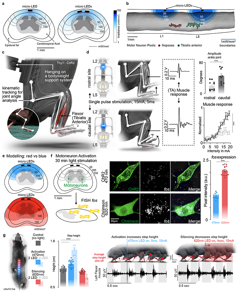
We complemented our anatomical model with finite element models of light penetration within the spinal cord (Fig. 3a, b). Simulations predicted that positioning the micro-LEDs above the dorsal horns would result in the most efficient photostimulation of afferent fibers and spinal interneurons (Fig. 3a). Compared to a die positioned over the midline of the spinal cord, this location minimized the impact of light-diffracting lipid-rich myelin on photon penetration.
Fig. 3. Targeted photostimulation across the entire spinal cord.
a, Simulations showing the penetration of blue light depending on the location of the micro-LED along the mediolateral direction.
b, Simulations predicting the optimal rostrocaudal location of the micro-LED to target activation to tibialis anterior and iliopsoas motoneurons; whose location was identified with intramuscular rabies injections.
c, Experimental setup to measure leg kinematics and muscle responses following targeted photostimulation of the lumbar spinal cord in Thy1-ChR2 mice.
d, Reconstructed leg movements and muscle responses following one pulse photostimulation delivered over the rostral versus caudal lumbar spinal cord. The bar plot reports the mean range of motion induced by the photostimulation (n = 10 mice, two-sided unpaired t-test, ***, p = 0.0021, meanmean±s.e.m.). The plot reports the area under the curve (AUC) of rectified muscle responses following photostimulation (n = 5 mice, ANOVA, ***, p < 0.0001, mean±s.e.m.)
e, Simulations reporting the attenuation of blue (470nm) versus red-shifted (620nm) photostimulation through spinal tissues.
f, Photographs showing the expression of the immediate early gene fos in motoneurons expression ChR2 or Chrimson following blue (470nm) versus red-shifted (620nm) photostimulation. Bar plots reporting the relative expression of fos mRNA following blue (470nm) versus red-shifted (620nm) photostimulation (n=14 /17 motoneurons for 470nm/620nm stimulation, n= 3 mice per group, two-sided unpaired t-test ***, p <0.0001, mean±s.e.m.).
g, Mice expressing ChR2 (470nm) and Jaws (600nm) in vGluT2 ON neurons are stepping on a treadmill while receiving pulses of blue (470nm, 2 LEDs) versus red-shifted (620nm, 2LEDs) photostimulation. Reconstructions of leg movements including foot trajectories and concomitant activity of the tibialis anterior muscles; shaded and empty boxes correspond to stance and swing phases, respectively. Bar graph reporting the step height for each condition (n > 30 steps per condition, n = 2 mice for 2 LEDs 470nm, n = 6 mice for 4 LEDs 470nm, n = 2 mice for 2 LEDs 620nm, n = 8 mice for 4 LEDs 620nm, one-way ANOVA, ***, p < 0.0001, mean±s.e.m.). Shaded bars represent mice that expressed a single opsin over the entire lumbar spinal cord and were activated with 4 LEDs.
Spatially-selective targeted photostimulation
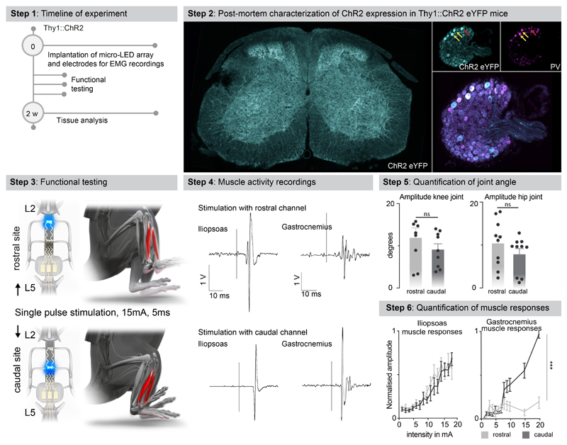
We sought to illustrate the relevance of these simulations to steer the configuration of micro-LED arrays that maximize the spatial selectivity of the photostimulation. Specifically, we asked whether the rostrocaudal location of the micro-LEDs was important to target specific motor pools.
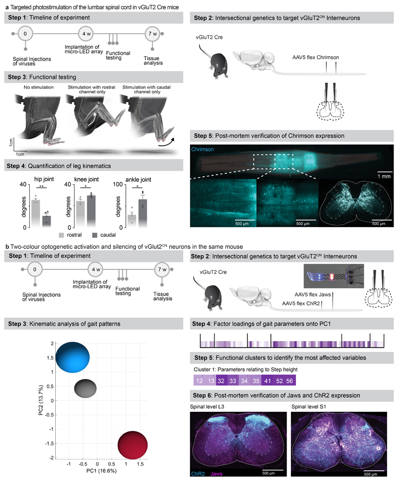
We visualized the anatomical location of tibialis anterior motoneurons using intramuscular PseudoRabies injections (Fig. 3b). Integration of this information into the computational model predicted that micro-LEDs positioned over the dorsal horns of caudal lumbar segments would maximize the photostimulation of neural pathways leading to the activation of motoneurons innervating the tibialis anterior (Fig. 3b-d). We validated these predictions in mice expressing channelrhodopsin (ChR2) in excitatory neurons, including proprioceptive neurons that project directly onto motoneurons (Extended Data Fig. 6). We fabricated a micro-LED array with two channels positioned over the dorsal horns of rostral and caudal lumbar segments. Photostimulation delivered from the LED channel targeting caudal lumbar segments elicited a robust muscle response in the tibialis anterior, which provoked a vigorous dorsiflexion of the foot (Fig. 3d, Extended Data Fig. 6, Supplementary Video 2). The amplitude of muscle responses increased linearly with the intensity of photostimulation (Fig. 3d). In comparison, photostimulation delivered over rostral lumbar segments elicited responses of smaller amplitude, as expected based on the distant location of the motor neurons innervating this muscle (Fig. 3d). These weaker responses were not due to a less efficient photostimulation per se, since the same photostimulation elicited a powerful hip flexion triggered by large muscle responses in the iliopsoas muscle, the motoneurons of which are embedded in the illuminated rostral lumbar segments (Extended Data Fig. 6). We reproduced these observations for the medial gastrocnemius muscle (Extended Data Fig. 6).
Photostimulation over the entire spectrum of light
The rapidly evolving library of experimental opsins is offering a broad repertoire of tools to target cellular mechanisms 27,28 . These opsins are activated by specific wavelengths spanning the entire spectrum of light. To be able to target any opsin with our micro-LED array, we integrated a silicone-phosphor composite coating over the micro-LED, which down-converted the emitted blue light toward the desired wavelengths without compromising the overall biointegration of the micro-LED array (Fig. 1b and Extended Data Fig. 2b).
We asked whether our micro-LED array could activate the red-shifted (590 nm) ChrimsonR opsins 29 from interneurons located in intermediate lamina. We expressed these opsins in vGlut2ON neurons using targeted injections of AAV-syn-flex-ChrimsonR-tdTomato in the spinal cord of vGlut2-cre mice (Extended Data Fig. 7). Activation of red-shifted LED channels positioned over the rostral or caudal lumbar segments elicited robust muscle responses that produced extensive movements of the hip or ankle, respectively (Extended Data Fig. 7, Supplementary Video 2). This spatial specificity mirrored the anatomical location of motoneurons innervating hip flexor muscles versus ankle flexor muscles (Fig. 3b).
Simulations predicted that red-shifted light could penetrate the entire depth of the spinal cord, whereas blue light extinguished rapidly when entering these tissues (Fig. 3e). Therefore, we asked whether red-shifted light allowed to target poorly-accessible motoneurons, which are nested in the deepest lamina of the ventral spinal cord. To test this prediction, we used intersectional genetics to express red-shifted or blue-activated opsins in sparse populations of motoneurons (Fig. 3f). While the limited number of targeted motoneurons was insufficient to elicit muscle contractions, the robust expression of the immediate early gene Fos in motoneurons revealed the sustained activation of these cells following 30 minutes of photostimulation with red-shifted light (Fig. 3f). In contrast, blue light failed to recruit motoneurons, thus confirming the predictions of the computational model (Fig. 3e).
This technology opened the possibility to achieve two-colour optogenetic activation and inhibition of targeted cell populations, which we tested in mice co-expressing ChR2 (470nm) and Jaws 30 (600nm) in vGlut2ON neurons (Fig. 3g and Extended Data Fig. 7). We prepared a micro-LED array with two spectrally-distinct light emission channels at two spatially-distinct rostrocaudal positions. In the same mouse, blue-light activation of vGlut2ON neurons elicited strong muscle responses, whereas inhibition of vGlut2ON neurons with red-shifted light reduced the vigor of locomotor movements (n = 3 mice; Fig. 3g).
Guideline for efficient and safe spinal cord photostimulation
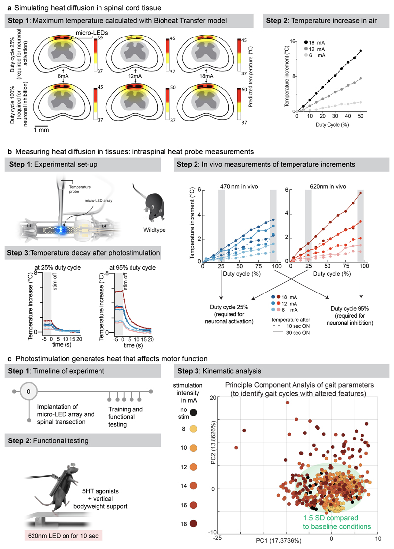
The reliable activation of opsins such as Jaws that drive hyperpolarization in neurons requires the delivery of sustained photostimulation. Duty cycles with extended stimulation-ON times can lead to tissue heating, which alters neuronal responses 22 . We assessed these thermal constraints comprehensively.
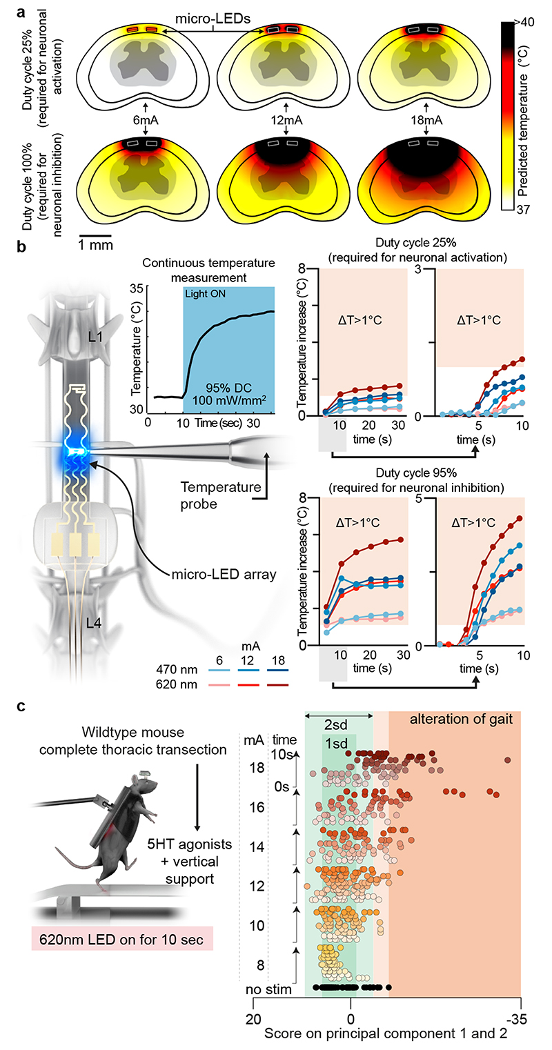
We performed simulations to predict the diffusion of heat in the spinal cord depending on the irradiance and duty cycle of photostimulation (Fig. 4a). Second, we measured the temperature directly within the posterior grey column of the spinal cord across the functional range of current intensities (Fig. 4b, Extended Data Fig. 8, Supplementary Video 3). These simulations and measurements identified time-windows and temporal delays between experiments to avoid alterations of neuronal responses and tissue damage.
Fig. 4. Guideline for effective yet safe spinal cord photostimulation.
a, Simulation of heat diffusion in spinal cord tissue with photostimulation protocols eliciting activation of ChR2 (25% duty cycle) or Jaws (95% duty cycle)
b, In vivo measurement of heat using a temperature probe inserted in the dorsal horn during photostimulation with the settings necessary to target ChR2 (25% duty cycle, wavelength 470nm, 2 LEDs, top) or Jaws (95% duty cycle, wavelength 620nm, 2 LEDs, bottom). The plots (and zoom-in windows) report the changes in temperature over time for three levels of intensity.
c, Wild-type mice with complete spinal cord injury are stepping on a treadmill following the reactivation of the lumbar spinal cord with 5HT agonists. The spinal cord is illuminated for 10 s, at various intensities. Kinematic recordings are conversated into a series of gait feature quantifications that are submitted to a principal component analysis. Locomotor performance is evaluated as the score on principal component 1 and 2. The plot reports the changes in locomotor performance over time for each tested photostimulation intensity (n = 3 mice).
To confirm these findings, we continuously illuminated the spinal cord of opsin-free mice with light of increasing intensity while the animals were stepping on a treadmill. To avoid interferences from volitional modifications of leg movements, we conducted these experiments in mice with complete spinal cord injury. We activated lumbar locomotor centers below the injury with a serotonergic pharmacotherapy that enabled automated stepping without contribution of the brain 31 . Clear locomotor deficits emerged during photostimulation. The extent of these deficits augmented with increasing time and radiant intensity (Fig. 4c, Supplementary Video 3).
These results establish a guideline for light-delivery parameters that enable reliable interrogation of spinal circuits in mice.
Ultrafast closed-loop control of photostimulation
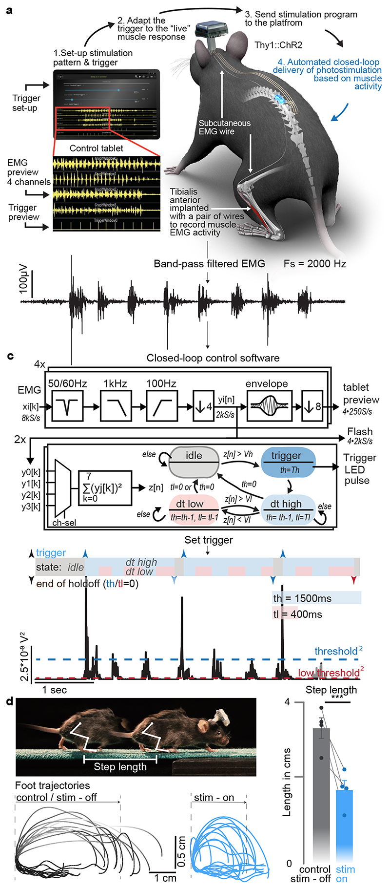
We next sought to illustrate the capabilities of our optoelectronic system for closed-loop photostimulation. We implemented a paradigm typically used in behavioral experiments and neuroprosthetic applications, wherein the onset of a burst of muscle activity instantly triggers photostimulation 32 . We conducted this experiment in Thy1-ChR2 mice, which were implanted with a micro-LED array targeting caudal lumbar segments (Supplementary Video 4).
We interfaced four pairs of thin wires and one reference (ground) wire with the wearable platform to acquire differential recordings of electromyographic (EMG) activity from chronically implanted leg muscles. EMG signals were sampled at 8 kS/s (per channel) with an analog bandwidth of 3.2 kHz (Fig. 5a, b). The signals were then conditioned on-chip to remove mains interference, apply a band-pass filter (100-1000 Hz), and down-sample to 2 kS/s. The processed signals were displayed in real-time on the tablet while the mouse was walking freely along a straight corridor without any constraint (Fig. 5d). The parameters for closed-loop photostimulation were configured on the tablet, but the control algorithm ran on the wearable platform. On-chip operations enabled closed-loop photostimulation with latencies as low as 15 ms (Extended Data Fig. 3). The control algorithm automatically delivered a brief single pulse of photostimulation (10 ms) each time a new burst of EMG activity was detected in the tibialis anterior muscle (Fig. 5c). Ultrafast EMG-triggered photostimulation induced a systematic and reproducible reduction of step length without impeding the continuous progression of the mice (Fig. 5d, Supplementary Video 4).
Fig. 5. Ultrafast closed-loop control of photostimulation to alter movement.
a, Wireless closed-loop optoelectronic system, including recordings of electromyographic signals from pair of wires chronically implanted into selected muscles and photostimulation. A tablet displays the signals and photostimulation events in real-time, and allows to configure the algorithms for closed-loop operations.
b, Conditioned (band-pass filter, mains interference suppression, down-sampling) recording of tibialis anterior activity
c, Signal conditioning and flow-chart of the closed-loop algorithm to determine the timing of photostimulation: The sum of the square values of eight consecutive samples (2kS/s) is taken as a short-term signal power measure z[n]. A stimulation is triggered for z[n]>Vh, then a timer set to th ensures that there is no further stimulation event for th milliseconds – except, if the signal power z[n] falls for longer than tl under Vl. Signal power measure z[n] and algorithm state for given threshold and hold-off times.
d, Thy1::ChR2 mouse walking freely while a single-pulse (10ms) of blue light (470nm, 2 LEDs) is delivered over caudal lumbar segments each time a burst of EMG activity is detected in the tibialis anterior muscle. Successive foot trajectory (toe marker) during walking without and with photostimulation. Bar graph reporting the step length for both conditions (n=4 mice, two-sided paired t-test, *, p < 0.0207, mean±s.e.m.)
Contribution of specific neurons and pathways to movement
We finally deployed a series of in vivo experiments to demonstrate the unprecedented versatility of our wireless optoelectronic system to interrogate key components of the locomotor circuitry in ecological environments or after neurological injury.
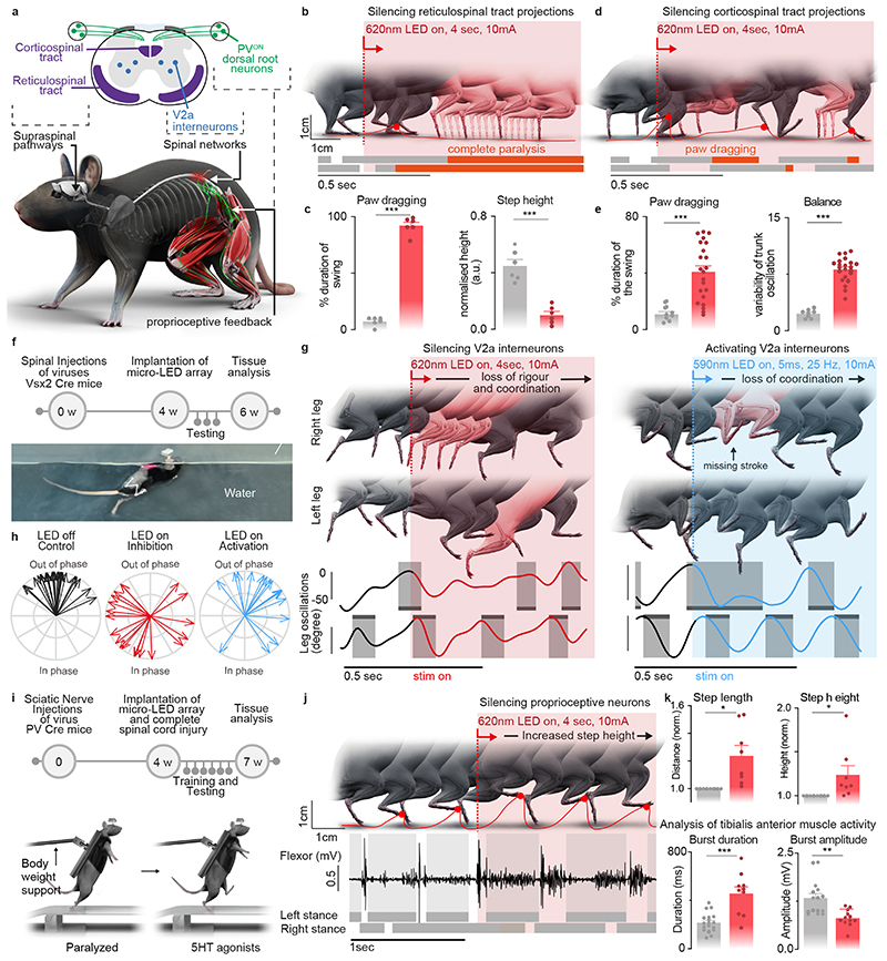
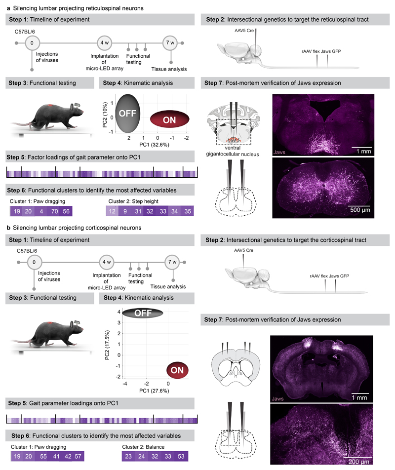
We asked whether the optoelectronic system could modulate descending pathways, even if the axons are confined to poorly accessible regions of the white matter. We used intersectional genetics to express Jaws along the entire extent of axons originating from neurons of the reticular formation that establish synapses within the lumbar grey matter (Extended Data Fig. 9). These axons extend in the poorly accessible lateral and ventral columns of the white matter, and terminate into ventral regions of the spinal cord. The reticular formation contributes to the production of locomotion and regulation of posture 26,33 . Sudden silencing of reticulospinal fibers during unconstrained locomotion arrested leg movements. This interruption lasted as long as the photostimulation was turned on (Fig. 6b-c, Supplementary Video 5). This result was unexpected, since such deficits were not detected when we silenced reticulospinal neurons using chemogenetics, which is a comparatively slow-acting method 26 . Therefore, we sought to replicate these observations when silencing the corticospinal tract (Fig. 6d, Extended Data Fig. 9). Previous studies showed that chemogenetic silencing 26 or ablation 34 of this pathway does not affect basic walking 33 . We found that the silencing of corticospinal tract fibers in the lumbar spinal cord during basic walking induced moderate paw dragging and trunk instability (Fig. 6e, Extended Data Fig. 9, Supplementary Video 5). These deficits resonate with the expected role of the corticospinal tract during walking in humans 35 . Together, these results emphasized the importance of fast perturbation dynamics to interrogate neural circuits.
Fig. 6. Contribution of specific neurons and pathways to movement.
a, Schematic showing the anatomical location of neurons and neural pathways that we targeted using intersectional genetics.
b, Reconstructed sequence of leg kinematics during walking while a red-shifted light (4 LEDs) is delivered over the spinal cord to silence reticulospinal tract projections. The occurrence of stance phases and paw dragging events is displayed for both legs below leg kinematics.
c, Bar plots reporting gait parameters most affected by the silencing of reticulospinal fibers (n = 3 mice, two-sided unpaired t-test***,p <0.0001, mean±s.e.m.)
d, Reconstructed sequence of leg kinematics during walking while a red-shifted light (4 LEDs) is delivered over the spinal cord to silence corticospinal tract projections. The occurrence of stance phases and paw dragging events is displayed for both legs below leg kinematics.
e, Bar plots reporting gait parameters most affected by the silencing of corticospinal tract fibers (n = 3 mice, two-sided unpaired t-test ***, p < 0.0001, mean±s.e.m.)
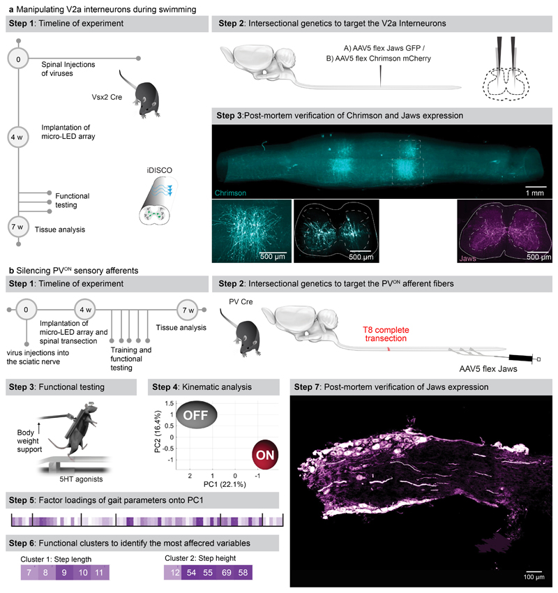
f, Timeline of experiments for targeted expression of Jaws (inhibition) or Chrimson (activation) in V2a interneurons. Photograph shows kinematic recordings during swimming along a water corridor.
g, Reconstructed sequence of left and right leg kinematics during swimming are shown in conjunction with the oscillations of both legs. Grey shared areas indicate the occurrence of a stroke. V2a interneurons were silenced or activated with sudden photostimulation over the lumbar spinal cord (620nm/590 nm, 4 LEDs).
h, Polar plot reporting the coordination between left and right strokes during swimming under the different experimental conditions (n = 3 mice)
i, Timeline of experiments for targeted expression of Jaw in PVON neurons of the dorsal root ganglia in mice.
j, Reconstructed sequence of leg kinematics during stepping together with EMG activity of the tibialis anterior muscle while a red-shifted light (4 LEDs) is suddenly delivered over the spinal cord to silence proprioceptive neurons
k, Bar plots reporting the step length, step height, and features of tibialis anterior EMG activity (n = 3 mice, two-sided unpaired t-test; *, p < 0.05; **, p < 0.01, ***, p<0.001, mean±s.e.m.)
We next aimed to demonstrate the ability of our optoelectronic system to manipulate deeply-located interneurons in ecological conditions. We expressed ChrimsonR or Jaws into Vsx2-expressing interneurons (Extended Data Fig. 10), which are involved in left-right alternation and locomotor vigour 36 . The sudden activation or inhibition of Vsx2-expressing interneurons during unconstrained swimming disrupted interlimb coordination (Fig. 6f-h, Supplementary Video 5).
Sensory feedback pathways are essential components of the circuits that produce locomotion, in particular after injury 37 . To illustrate the ability of the optoelectronic system to modulate these pathways, we expressed Jaws in proprioceptive neurons located in the dorsal root ganglia of mice with complete spinal cord injury (Extended Data Fig. 10). All the paralyzed mice exhibited robust locomotion in response to the serotonergic pharmacotherapy. Sudden silencing of proprioceptive feedback circuits mediated an unexpected augmentation in the vigor of locomotor movements, which led to an increase in step height associated with extended duration of bursts in ankle flexor muscles (Fig. 6k, Supplementary Video 5). These behavioral responses were transient, since the increase in step height only lasted for 6 to 10 steps before the mice collapsed.
Discussion
We resolved the challenges underlying the conception of a chronic optoelectronic system that enables the safe, long-term closed-loop photostimulation of any targeted neurons or pathways throughout the mouse spinal cord under untethered, unrestricted and ecological conditions. We also established a guideline for spinal cord optogenetics in mouse models in order to conform epidural implants to spinal cord statics and dynamics, optimize LED positioning, and avoid tissue heating that alters neuronal responses.
When designing this system, we aimed to include all the desired features of spinal cord optogenetics. We conceived a system wherein a conformable array accommodates tailored configurations of micro-LEDs with customizable emission spectra, allowing concurrent multicolor illuminations of targeted neuronal populations distributed across various locations of the spinal cord, including deep regions. This versatility befits the functional interrogation of any targeted neurons within the dorsal root ganglia or spinal cord, as well as any white matter embedded axons from any targeted neuronal pathways.
With few exceptions, functional interrogation of spinal pathways has been limited to permanent ablations, or slow acting manipulations like chemogenetics 38 (minutes to hours) or conditional cell ablations 39 (weeks or longer). Our system allowed us to perform a series of experiments that revealed the incompatibility of these timescales with the study of dynamic circuit interactions, which emerge within millisecond windows. For example, we previously showed that chemogenetic silencing of excitatory reticulospinal or corticospinal tract neurons had no detectable impact on locomotor control in intact mice 26 . Instead, we found that the sudden silencing of these descending pathways within lumbar segments led to clear gait deficits, which depended on the specifically targeted pathway. The sudden silencing prevents redundant systems from compensating for the missing inputs, which likely occurs during slow-acting interventions 40 . It is also possible that the silencing within the spinal cord leads to incongruent commands, especially from cortical neurons that multiplex executive commands through various descending pathways, in addition to direct inputs to the spinal cord. In the same vein, we observed an unexpected increase in the amplitude of locomotor movements when silencing proprioceptive feedback circuits. This counter-intuitive response could not be predicted from previous genetic ablation experiments of proprioceptive afferents that reported sustained gait deficits after the loss of proprioception 41,42 . While the mechanisms underlying these transient responses require further investigation, our results stress the importance of fast perturbation dynamics to interrogate the function of spinal circuits involved in the production of motor behaviors.
Clinical trials have started assessing the safe use of opsins for treating neurological deficits in patients 43 . Since the spinal cord is a primary target of optogenetic-based therapies, clinical optogenetics will trigger a surge of interest in medical devices capable of illuminating the spinal cord 2 . In this respect, our wireless optoelectronic system obeys the key principles underlying the ecological design of medical devices 44 , thus opening a pathway to develop systems for the human spinal cord.
Methods
Micro-LED array fabrication
The fabrication of the micro-LED array is illustrated in Extended Data Fig. 2a. The fabrication started with the spin-coating of a 2.4 μm-thick layer of polyimide (PI2610, HD Microsystems GmbH) on a 4-inch silicon wafer coated with Ti/Al layers (5/100 nm). Following curing of the polyimide (2 hrs at 300°C in a N2 oven), a Ti/Au/Ti film (5/250/5 nm) was sputtered after O2 plasma surface activation (AC450, Alliance Concept). Photolithography (AZ1512, MicroChemicals) and successive wet and reactive ion etchings patterned the metallization layer. The latter was encapsulated with a second layer of polyimide (2 μm-thick). The polyimide-metal-polyimide stack was next patterned with photolithography (AZ9260, MicroChemicals) and RIE etching. Then, a SiO2 layer (15 nm) was sputtered on the patterned polyimide structures, followed by the spin-coating of a 20 μm-thick layer of PDMS (Sylgard 184, Dow Corning). A 3rd photolithography (AZ40XT, MicroChemicals) and RIE etching of the PDMS revealed the device shape and defined the micro-LED integration sites. Small bumps of solder paste (~50 μm ⌀, SMDLTLFP10T5, Chipquik) were manually deposited on the contact pads. Next, micro-LEDs (TR2227, Cree Inc.) were positioned onto these pads using a pick-and-place equipment (JFP Microtechnic). The wafer was then placed on a hotplate at 165°C to electrically and mechanically bond the micro-LEDs. For hermeticity, a 12 wt% solution of polyisobuthylene (PIB, Oppanol, BASF) in cyclohexane (Sigma-Aldrich) was drop-casted at the die surface via pneumatic printing. To target activation of red-shifted opsins, a PDMS-phosphor composite (50 wt %, OR02 or R620, PhosphorTech) was printed over PIB-covered blue micro-LEDs. A final encapsulating layer of PDMS (60 μm-thick) was printed at the surface of the substrate, placing the interconnect’s metallization layer in the mechanical neutral plane. The circuit pads were soldered to copper wires (CZ 1103, Cooner wires), then sealed with silicone (734, Down Corning). Finally, the micro-LED array was released from the wafer by anodic dissolution of the Al layer (2V bias in a NaCl saturated H2O solution).
Wireless recording and stimulation platform
We used two versions of the platform. The first version, which did not include recording capabilities, has been described in detail previously 12 . The second version is a substantially improved system that includes our custom system-on-chip (SoC) 25 . It incorporates the LED driver of the previously used front-end chip, but extends far beyond in functionality. It features 9 channels for low-voltage (ExG) signal acquisition, 4 current acquisition channels, 32 LED driving channels, 1 complex impedance measurement channel, 6-electrical neural stimulation channels, and a 4+1-core microcontroller unit (MCU). In the wireless unit, the limited pin-count of the small head-mounted connector (16-pin connector, A79113-001, Omnetics) constrained us to interface only 4 differential ExG, 1 differential current sensing, and 2 LED driving channels. The antenna design was revised and is discussed in more detail below. The device further features a 256MB flash storage device (GD5F4GQ4RCYIG, GigaDevice) for long-term recording of raw signals and experiment protocols, and a Bluetooth Low-Energy (BLE) SoC (nRF5283, Nordic Semiconductor) for wireless connection to an Android tablet PC running a dedicated app.
The custom integrated circuit (IC) SoC was fabricated in a 130nm 1P8M CMOS technology with MIM capacitor and SAB resistor options. The 20.8 mm2 chip-die was wire-bonded into a 7·7 mm2 169-pin ball-grid-array (BGA) package and thus compatible with standard electronics assembly and soldering work flows. The printed circuit board (PCB) was manufactured in a standard industrial technology: 6 copper layers in FR4 with 1.0 mm overall thickness, >75 μm features/clearances/drill. Components were placed manually and soldered in a reflow oven (5min, 230°C max.), one side at the time. The system was powered by a 12-35 mAh Li-Ion battery (GMB031009/GMB501113, Guangzhou Markyn Battery Co., Ltd.). This battery enables 3.5 to 11 hours of operations in closed-loop mode, assuming an average delivery of two current pulses per second with a duration of 5 ms and an intensity of 15mA. The headstage can be detached from the mouse and recharged in between experiments. For longevity, the bonds between PCB, connector, and battery were reinforced with epoxy and the whole device encapsulated in silicone (730, Dow Corning).
Design and fabrication of the antenna
We designed a physically small antenna which can be produced in a simple standard industrial PCB technology and thus directly integrated into a PCB design. The 3D-microstrip antenna design is illustrated in Extended Data Fig 3. We started with a λ/4-antenna folded into a square which was realized with 0.4 mm microstrip traces on the top and bottom layers and 0.2 mm/0.4 mm through-vias. A row of vias in a defined distance (0.2mm) from the antenna trace acts as ground plane in the third dimension. It shields the antenna from PCB-design-specific influences and detunes it reproducibly, enabling an electrically smaller antenna. Antenna impedance is matched with a π network to the radio frequency (RF) IC, the exact values for which were found in a series of return loss (S11) measurements and completed with antenna gain measurements in the anechoic chamber. Antenna radiation characteristics measurements are reported in Figure 1g.
Animal models
Experiments were conducted on adult male or female C57BL/6 mice (18-35g body weight, 8-25 weeks of age). Thy1::ChR2 (Jackson Laboratory 12350), vGluT2 Cre (Jackson Laboratory 016963), Parvalbumin Cre (Jackson Laboratory 017320) and Vsx2 Cre (MMMRRC 36672, also called Chx10 Cre) transgenic mouse strains were used and maintained on a mixed genetic background (C57BL/6). Housing, surgery, behavioural experiments and euthanasia were performed in compliance with the Swiss Veterinary Law guidelines. Animal care, including bladder voiding, was performed twice daily for the time of the experiment. All procedures were approved by the Veterinary Office of the Canton of Geneva.
Viruses and virus production
Viruses used in this study were either acquired commercially or produced locally. The following plasmids were used and detailed sequence information is available as detailed or upon request: AAV-Dj-hSyn Flex mGfp 2A Synaptophysin mRuby (Stanford Vector Core Facility, reference AAV DJ GVVC-AAV-100, titre 1.15 x 10^14 GC/ml), AAV pmSyn1-EBFP-Cre (Addgene Plasmid 51507), AAV-Syn-FLEX-ChrimsonR-tdT (Addgene 62723), AAV-CAG-FLEX-Jaws-KGC-GFP-ER2 (Addgene 84445), AAV-EF1a-double floxed-hChR2(H134R)-mCherry (Addgene 20297). All flexed AAV vectors used in the present study showed transgene expression only upon Cre-mediated recombination. Pseudorabies tracing was completed using Bartha strain PRV152 (expressing GFP; 4.9 × 10⁹ pfu per ml, Princeton University). Injection volumes, coordinates and experimental purpose are described below.
Surgical Procedures
General surgical procedures have been described previously in detail 26 . Surgeries were performed under aseptic conditions and under 1-2% isoflurane in 0.5-1 l/min flow of oxygen as general anesthesia. After surgeries, mice were allowed to wake up in an incubator. Analgesia, Buprenorphine (Essex Chemie AG, Switzerland, 0.01-0.05 mg/kg s.c.) or Rimadyl (5 mg/kg), was given twice daily for 2-3 days after surgery.
Implantation of the micro-LED array
The interlaminar spaces between vertebrae T12/T13 and L2/L3 were dissected to expose the exit and entry points, respectively, for the implant. A 6-0 ethilon suture (MPE697H, Ethicon EMEA) was passed through the epidural space from T12/T13 to L2/L3, then through the silicone loop of the implant and back through the epidural space. The implant was slid over the spinal cord by gently pulling both ends of the suture rostrally. The connector of the implant was fixed by suturing paraspinal muscles across the connector. The percutaneous connector (16-pin connector, A79112-001, Omnetics Connector Corporation, USA) and wires were routed subcutaneously to the head. Three screws (PN: AMS120/5B-25, Antrin miniature specialties) were inserted into the skull, surrounding the percutaneous connector. Fresh dental cement was then poured around the screws and connector, and held in place until cured. The wireless recording and stimulation platform can easily be attached and detached to this connector during behavioural experiments.
Spinal injections
For lumbar cord injections, the interlaminar spaces between T13/L1 and L1/L2 were dissected. Injections were performed using a pulled glass pipette driven with the Nanoliter pump (Nanoliter 2010 injector, World Precision Instruments) fixed to a stereotaxic frame. Two injections were made on either side of the spinal cord per interlaminar space. 50 nl at a rate of 100 nl/sec were injected at 0.6 mm and at 0.3 mm below the dorsal surface of the spinal cord.
Brain injections
An incision was made across the skull. For targeting corticospinal neurons in Layer V motor cortex, bregma was identified and a craniotomy 1 mm-2 mm medial and −0.5 mm to 2 mm rostro-caudally was performed with a hand-held drill. 100 nl injections at 3 nl/sec were made bilaterally at medial-lateral 1.2 mm and 1.7 mm, rostro-caudally at 0mm, −0.5mm, −1mm and −1.5 mm, dorso-ventrally at a depth of 0.5 mm from the brain surface. For targeting descending neurons in the reticulospinal formation, bregma was identified and a craniotomy 5 mm-6 mm dorsal and 0 mm-2 mm lateral to Bregma was performed. 100 nl injections at 3 nl/sec were made bilaterally at medial-lateral 0.3 mm, rostro-caudally at −5.8 mm and −6.2 mm, dorso-ventrally at a depth of 5.6 mm from the brain surface.
Muscle and sciatic nerve injections
An incision was made in the skin above the belly of the muscle of interest. 3.5 μl of virus was injected in total per muscle with a 10 μl Hamilton injection syringe. For sciatic nerve injections, an incision was made above the biceps femoris. The muscles overlying the sciatic nerve were blunt dissected until the nerve was exposed. 2 μl of virus was injected into the nerve with a 10 μl Hamilton syringe.
Intersectional virus targeting strategies
For targeting transgene expression to motor neurons, an rAAV pmSyn1-EBFP-Cre was injected into the sciatic nerve and an AAV5 Syn-FLEX-ChrimsonR-tdT or AAV5-EF1a-double floxed-hChR2(H134R)-mCherry into the lumbar spinal cord. For targeting vGlut2 interneurons in the spinal cord, an AAV5 CAG-FLEX-Jaws-KGC-GFP-ER2 and/or AAV5 Syn-FLEX-ChrimsonR-tdT was injected into the lumbar spinal cord. For targeting the reticulospinal or corticospinal tract, an AAV5 pmSyn1-EBFP-Cre was injected into the reticular formation or layer V motor cortex combined with a rAAV CAG-FLEX-Jaws-KGC-GFP-ER2. For targeting V2a interneurons, an AAV5 CAG-FLEX-Jaws-KGC-GFP-ER2 or AAV5 Syn-FLEX-ChrimsonR-tdT was injected into the lumbar spinal cord.
EMG implantation
An incision over the muscle of interest (tibialis anterior, gastrocnemius) was made and if needed the muscle was exposed by blunt dissection of overlying tissue. Bipolar intramuscular electrodes were inserted into the muscle parallel to the muscle fiber orientation. To confirm optimal placing, the wires were electrically stimulated resulting in a muscle. Electrodes were fixed in place by suturing either side of the electrode that exited the muscle 45 . A grounding wire was implanted subcutaneously. Wires were connected to a percutaneous connector (Omnetics Connector Corporation, USA) cemented to the skull.
In vivo temperature measurement
The skin was incised over the thoracic and lumbar spinal cord. A laminectomy at vertebral level T13 and L1 was performed. A suture was passed from the L2/L3 intralaminar space to the exposed spinal cord. The suture was passed through the loop of the spinal micro-LED array and passed back under the lamina to L2/L3. The implant was placed over the spinal cord with the distal end under L2. The temperature probe (MT-4 thermocouple microprobe, physitemp instruments Inc) was inserted and fixed at L1. The spinal cord was photostimulated at 6, 12 and 18mA at increasing duty cycles (5%-100%; intervals of 5%) for 30 seconds at a time. We continuously recorded the temperature in the spinal cord.
Algorithm for closed-loop application
The four EMG signals xi[k] were acquired with 3.2 kHz of analog bandwidth at 8 kS/s. It was then conditioned (mains interference and band-pass filtering) and down-sampled to 2 kS/s, yi[n], on-chip by MCU software. The yi[n] signals were stored to the on-device flash memory and were further processed for both the tablet preview (a low sampling rate envelope) and closed-loop stimulation triggering: the sum of the square values of eight consecutive samples was taken as a short-term signal power measure z[m]. The user can set (via the tablet user interface) various parameters: a higher- Vh and lower Vl threshold value and high- th and low tl dead-times. A stimulation was triggered for z[m]>Vh, then a timer set to th ensures that there is no further stimulation event for th seconds – except, if the signal power z[m] fell for longer than tl under Vl. Separate trigger conditions can be set for the two LED driving channels.
Spinal cord injury model
A laminectomy was made at midthoracic level T7/8. The spinal cord was completely transected with microscissors. To confirm the completeness of the transection, the cut was retraced with a 32G needles. Muscles were sutured over the exposed spinal cord and the skin was sutured.
Training
One week after transection injury, mice were trained daily on a locomotor task. Five minutes before training, the mice received subcutaneous injections of quipazine (5-HT2A/C, 0.2-0.3mg/kg) and intraperitoneal injections of 8-OH-DPAT (5HT1A/7, 0.05-0.2mg/kg). The dose was adjusted based on locomotor performance. Training was conducted bipedally on a treadmill (9cm/sec, Robomedica, USA) with adjustable robotic bodyweight support for 20 minutes daily.
Behavioural assessments
The wireless recording and stimulation platform was gently attached the mouse’s head connector prior to behavioral experiments. Stimulation paradigms for photostimulation required for neuronal activation consisted of 5ms pulses at 50Hz (25% duty cycle) and photostimulation required for neuronal inhibition consisted of 20ms pulses at 50 Hz (100% duty cycle). All other procedures have been described in detail previously 46 . Limb motor movements was evaluated while running on a treadmill, on a horizontal ladder or during swimming across a straight pool of water. Bilateral leg kinematics were captured either with the Simi Reality Motion Systems (combining up to 4 cameras) for markerless tracking with DeepLabCut 47 or with the Vicon Motion Systems, UK (combining 12 infrared cameras) for tracking with reflective markers on the crest, hip, knee, ankle joints and distal toes. The limbs were modelled as an interconnected chain of segments and gait parameters were calculated from those. Electromyographic signals (2kHz) were amplified (1k), filtered (100-1k bandwidth, A-M Systems Differential AC Amplifier Model 1700) and digitalised either with the Vicon System or with the Powerlab system (AdInstruments). The traces were analysed offline with LabChart.
Analysis of kinematic data
A total of 78 gait parameters were computed for each limb for each gait cycle. All parameters are reported in Supplementary Table 1. To evaluate differences between timepoints post-implantation or experimental conditions, as well as to identify the most relevant parameters explaining these differences, we implemented a multistep principal component analysis.
Perfusions
Mice were perfused at the end of the experiments. Mice were deeply anesthetized by an intraperitoneal injection of 0.2 ml sodium pentobarbital (50 mg/ml). Mice were transcardially perfused with PBS followed by 4% paraformaldehyde in PBS. Tissue was removed and post-fixed for 24 hrs in 4% paraformaldehyde before being transferred to PBS or cryoprotected in 30% sucrose in PBS.
Computerized tomography
Once perfused, the mouse was placed in a 50 ml Falcon tube. The mouse was scanned in a micro-CT Quantum GX (Perkin Elmer, Waltham, MA, USA) with a FOV of 25 mm at 90 kV and 80 mA over 360° (Angle 0.45°) using the high-resolution 14-min protocol. The projections obtained were then reconstructed at a voxel size of 50 μm or 20 μm using the Quantum GX software. Segmentation was performed with Analyze 12.0 (AnalyzeDirect, Inc., USA).
Magnetic resonance imaging
The mice were placed in a Falcon tube which was filled with Galden® (Fluorochem, Hadfield, UK) to match the tissue magnetic susceptibility and improve magnetic field homogeneity around the cord. Mouse cords were scanned on a 9.4T MR system (Varian Medical Systems, Palo Alto, CA, USA) equipped with 400 mT/m gradients, using a 3.5-mm diameter birdcage coil for radiofrequency transmission and reception. High-resolution axial anatomical images were acquired using a fast spin-echo sequence (in-plane resolution: 47 x 47 μm2, FOV: 12x12 mm2, matrix size: 192x192 zero-filled to 256x256, slice thickness: 0.5 mm, 20 slices, TE/TR = 13/5000 ms, echo train length: 4, TEeff = 13 ms, 24 averages, scan time = 1h36min).
Computational simulations
An anatomically accurate 3D finite element model of the mouse spinal cord was generated. First, sagittal sections of the grey and white matter were extracted from an atlas of the spinal cord 48 . Secondly, these sections were placed and scaled manually to fit the collected MRI data. In turn, the cerebrospinal fluid and epidural fat were first segmented from the same datasets, then sections were extracted and smoothed. All sections were lofted together to generated 3D volumes (Sim4Life by ZMT). The LEDs were approximated as three-layer rectangular structure consisting of PIB, PDMS and SiC (TR2227, Cree Inc.). The entire geometry was encapsulated into a cylindrical volume to approximate the surrounding tissues as saline. All volumes were imported into COMSOL and discretized into a tetrahedral mesh with extremely fine element size (COMSOL Multiphysics® v. 5.3. www.comsol.com. COMSOL AB, Stockholm, Sweden). Physics-based simulations of the bioheat transfer and the light penetration were applied. For the former the bioheat transfer equations were utilized for which thermal conductivity, density and heat capacity values were exported from an atlas of such values in Sim4Life (https://itis.swiss/virtual-population/tissue-properties/database/thermal-conductivity/). Dirichlet boundary conditions were applied at the outermost surface of the saline volume. A heat source was applied at the appropriate layer for each simulation. The light penetration was calculated with the Helmholtz equations. Scattering and absorption coefficients were taken from various prior publications 49–51 . Optical parameters of the model are reported in Supplementary Table 2. Dirichlet boundary conditions were implemented for the optrode contacts and the outermost surface of the saline volume. A parametric sweep was applied for the power density with the irradiance with values of 50, 100 and 150 mw/mm2.
X-ray videography
To collect high-speed X-ray video data, animals were positioned in a 15 cm x 5 cm x 5.5 cm Plexiglas box oriented perpendicular to the beam of a custom-built X-ray video system (Philips BV 25, 64 kV, 2 mA). The transparent box allowed continuous observation of the mouse with an infrared video camera to trigger the X-ray acquisition at the right moment. The rays were detected by a flat panel detector (196 Hz, Dexela 1207) and acquired with a frame grabber (Matrox Solios eCL-B). Fifteen trials of 10 sec length were acquired per animal. Communication with the detector device, video acquisition, and correction of image distortions were carried out using custom-made software (MATLAB, The MathWorks).
Optical measurements
The optoelectronic devices were laminated on a large photodiode (S170C, Thorlabs) and covered with a custom-built reflective piece. The captured light power was measured using an optical power meter (PM100D, Thorlabs). For measurements involving micro-LEDs covered with phosphor-PDMS composite, the converted light (λ = 590 or 620 nm) and the transmitted blue light (λ = 470 nm) powers were quantified individually using optical filters with cut-off λ = 500 nm (FES0500, FEL0500, Thorlabs).
Accelerated ageing
To assess the long-term functionality of the micro-LED array and the safety of its encapsulation over time, accelerated ageing experiments were conducted. The optoelectronic devices were immersed in PBS with a pH of 7.4 (1X, Gibco), and its test tube was sealed with parafilm. Then, the devices were stored in an incubator at 67°C, resulting in a six-fold acceleration compared to the mouse body temperature (37°C). Measurements were carried at room temperature using a constant current source (Keithley 2400 SourceMeter, i = 5 mA).
Optoelectronic characterization under stretch
In order to evaluate the stable functionality of the micro-LED array under mechanical strain, cycling experiments were performed. The devices were mounted on a custom-built uniaxial stretcher and stretched to 1.15 of their initial length for 100k cycles (1 stretching cycle to maximal strain per second). The voltage was monitored continuously while applying i = 5 mA (Keithley 2400 SourceMeter). The stretcher and the measurement equipment were controlled and synchronized using custom-made software based on LabVIEW 2015 (National Instruments).
Immunohistochemistry
Perfused post-mortem tissue was cryoprotected in 30% sucrose in PBS for 48 hours before being embedded in cryomatrix (Tissue Tek O.C.T, Sakura Finetek Europe B.V.) and freezing. 30 μm thick transverse sections of the spinal cord were cut on a cryostat (Leica), immediately mounted on glass slides and dried. Sections were blocked with 10% bovine serum albumin in PBS for 60 minutes. Then sections were incubated with following primary antibodies diluted in blocking solution at room temperature overnight: rabbit anti-GFAP (1:1000, Dako Z0334), anti-Iba1 (1:1000, FUJIFILM Wako 019-19741). Slides were washed 4 times with PBS before the secondary antibodies (Alexa Fluor Conjugated, Invitrogen) were applied for 90 minutes in blocking solution; Alexa. Slides were washed 4 times with PBS and cover slipped with Mowiol. Immunofluorescence was imaged digitally using a slide scanner (Olympus VS-120 Slide scanner) or confocal microscope (Zeiss LSM880 + Airy fast module with ZEN 2 Black software (Zeiss, Oberkochen, Germany)). Images were digitally processed using ImageJ (ImageJ NIH) software or Imaris (Bitplane, v.9.0.0).
Fluorescence in-situ hybridization
Motor neurons were examined for co-localization of fos mRNA using the RNA labelling kit from Molecular instruments (Molecular instruments, USA). Sections on slides were covered with 5x SSCT (20x SSC buffer, Invitrogen, USA; 10% Tween 20, Applichem, Germany) for 10 min and then pre-hybridized in 30% probe hybridization buffer (Molecular instruments, USA) for 30 min at 37°C. Sections were hybridized overnight at 2 μM probe concentration (for fos or parvalbumin) in 30% probe hybridization buffer at 37°C. Following hybridization, slides were washed in a solution of 30% probe wash buffer (Molecular instruments, USA) and 5x SSCT four times for 15 mins. Sections were then incubated in an amplification buffer (Molecular instruments, USA) for 30min at room temperature. In the meantime, fluorophore-labeled HCR hairpins (Molecular instruments, USA) were snap-cooled (heating at 95°C for 90sec) and cooled down to room temperature. Amplification was performed overnight at room temperature at a concentration of 120 nM per hairpin in the amplification buffer. Following amplification, samples were washed in 5x SSCT for at least 2 times 30 min to remove unbound hairpins. Lastly, sections were air-dried and cover slipped using Mowiol (Calbiochem, USA).
iDisco+ clearing
The mouse spinal cord and brains were processed with the iDisco+ for 3D imaging 52 . The detailed protocol and recommended antibody concentrations can be found on following website: http://www.idsico.info.
3D-imaging of cleared samples
Imaging was performed using a customized MesoSPIM lightsheet microscope 53 . Images were acquired with a 2x objective when using the MesoSPIM. At 2x magnification on the MesoSPIM, the pixel resolution was 3.26 x 3.26 x 3 μm in x-, y-, and z-direction. Image acquisition generated 16-bit TIFF files, and stitching of files was performed using arivis Vision4D (Arivis AG, Munich, Germany). Imaris (Bitplane, v.9.0.0) and arivis Vision4D (Arivis AG, Munich, Germany) were used to generate 3D reconstructions and optical sections of the raw images.
Statistics and Reproducibility
All data are reported as mean values ± s.e.m. unless stated otherwise. Behavioral assays were replicated several times (3 to 10 times depending on the experiments) and averaged per animal. Statistics were then performed over the mean of animals. Statistical analysis was performed in GraphPad Prism (USA) using two-sided paired or unpaired Student’s t-tests, one-way ANOVA for neuromorphological evaluations with more than two groups, and one- or two-way repeated-measures ANOVA for functional assessments, when data were distributed normally. Post hoc Tukey’s or Bonferroni test was applied when appropriate. The significance level was set as p < 0.05. The nonparametric Mann-Whitney or Wilcoxon signed-rank tests were used when comparisons involved less than 5 mice. Fluorescent labelling of structures targeted by viral vector injections were confirmed in every experimental animal. If labelling was absent, mice were excluded from the study. If labelling was present, it was similar across mice.
Extended Data
Extended data Figure 1.
Extended data Figure 2.
Extended data Figure 3.
Extended data Figure 4.
Extended data Figure 5.
Extended data Figure 6.
Extended data Figure 7.
Extended data Figure 8.
Extended data Figure 9.
Extended data Figure 10.
Supplementary Material
Acknowledgements
We are grateful to Dr Bernard Schneider for providing viral vectors; Dr Laura Batti and Dr Stéphane Pagès from the ALICe platform for light sheet imaging. Financial support was provided by a Consolidator Grant from the European Research Council [ERC-2015-CoG HOW2WALKAGAIN 682999], the Swiss National Science Foundation [subsides 310030_130850, CRSII5_183519, BSCGI0 1578000] and the European Union’s Horizon 2020 Framework Programme for Research and Innovation under the Specific Grant Agreement No. 785907 (Human Brain Project SGA2) and the Bertarelli Foundation. C.K. is supported by a Marie Skłodowska-Curie postdoctoral fellowship and HFSP long-term fellowship (LT001278/2017-L). S.S. and C.I.D.Z. are supported by grants from BIG (Erasmus MC), Medical-NeuroDelta, and INTENSE (LSH-NWO).
Footnotes
Author Contributions. C.K., F.M. and P.S. contributed equally to this work. G.C. and S.P.L. contributed equally to this work. F.M. developed and collaborated with V.P. and K.K. for the production of spinal implants. C.K., F.M., I.F., S.S. and T.H.H. carried out the experiments and analysis. P.S., N.B. and Q.H. developed the head-mounted wireless stimulation device. I.J. performed MR imaging. A.P. carried out the high-speed x-ray videography. A.R. and J.G. analyzed imaging data. A.R. and N.A. conducted computational simulations. J.R. generated the figures and conceived the illustrations with contributions of C.K., F.M. and P.S., S.P.L. and G.C. conceived and supervised the study. G.C. and S.P.L. secured funding. G.C. wrote the paper with S.P.L., C.K., F.M. and P.S., and all the authors contributed to its editing.
Competing Interests Statement. The authors declare competing financial interests: G.C. and S.P.L. are founders and shareholders of Onward medical, a company with partial relationship to the present work.
Data Availability
The Source data files can be found with the online supporting information. Further data that support the findings will be made available upon reasonable request to the corresponding authors.
References
- 1.Deisseroth K. Optogenetics. 2011;8:26–29. doi: 10.1038/nmeth.f.324. [DOI] [PMC free article] [PubMed] [Google Scholar]
- 2.Won SM, Song E, Reeder JT, Rogers JA. Emerging Modalities and Implantable Technologies for Neuromodulation. Cell. 2020:1–21. doi: 10.1016/j.cell.2020.02.054. [DOI] [PubMed] [Google Scholar]
- 3.Roy A, et al. Optogenetic spatial and temporal control of cortical circuits on a columnar scale. J Neurophysiol. 2016;115:1043–1062. doi: 10.1152/jn.00960.2015. [DOI] [PMC free article] [PubMed] [Google Scholar]
- 4.Jeong JW, et al. Wireless Optofluidic Systems for Programmable In Vivo Pharmacology and Optogenetics. Cell. 2015 doi: 10.1016/Jcell.2015.06.058. [DOI] [PMC free article] [PubMed] [Google Scholar]
- 5.Kim T, Il, et al. Injectable, cellular-scale optoelectronics with applications for wireless optogenetics. Science (80-) 2013 doi: 10.1126/science.1232437. [DOI] [PMC free article] [PubMed] [Google Scholar]
- 6.Montgomery KL, et al. Wirelessly powered, fully internal optogenetics for brain, spinal and peripheral circuits in mice. 2015;12:3–5. doi: 10.1038/nmeth.3536. [DOI] [PMC free article] [PubMed] [Google Scholar]
- 7.Qazi R, et al. Wireless optofluidic brain probes for chronic neuropharmacology and photostimulation. Nat Biomed Eng. 2019 doi: 10.1038/s41551-019-0432-1. [DOI] [PubMed] [Google Scholar]
- 8.Shin G, et al. Flexible Near-Field Wireless Optoelectronics as Subdermal Implants for Broad Applications in Optogenetics. Neuron. 2017 doi: 10.1016/Jneuron.2016.12.031. [DOI] [PMC free article] [PubMed] [Google Scholar]
- 9.Montgomery KL, Iyer SM, Christensen AJ, Deisseroth K, Delp SL. Beyond the brain: Optogenetic control in the spinal cord and peripheral nervous system. Sci Transl Med. 2016;8:337rv5. doi: 10.1126/scitranslmed.aad7577. [DOI] [PubMed] [Google Scholar]
- 10.Gutruf P, Rogers JA. Implantable, wireless device platforms for neuroscience research. Current Opinion in Neurobiology. 2018 doi: 10.1016/Jconb.2017.12.007. [DOI] [PubMed] [Google Scholar]
- 11.Xue Y, et al. A wireless closed-loop system for optogenetic peripheral neuromodulation. Nature. 2018 doi: 10.1038/s41586-018-0823-6. [DOI] [PMC free article] [PubMed] [Google Scholar]
- 12.Michoud F, et al. Epineural optogenetic activation of nociceptors initiates and amplifies inflammation. Nat Biotechnol. 2020 doi: 10.1038/s41587-020-0673-2. [DOI] [PMC free article] [PubMed] [Google Scholar]
- 13.Caggiano V, Sur M, Bizzi E. Rostro-Caudal Inhibition of Hindlimb Movements in the Spinal Cord of Mice. 2014;9 doi: 10.1371/journal.pone.0100865. [DOI] [PMC free article] [PubMed] [Google Scholar]
- 14.Lu C, et al. Flexible and stretchable nanowire-coated fibers for optoelectronic probing of spinal cord circuits. Sci Adv. 2017;3 doi: 10.1126/sciadv.1600955. [DOI] [PMC free article] [PubMed] [Google Scholar]
- 15.Park S, Il, et al. Soft, stretchable, fully implantable miniaturized optoelectronic systems for wireless optogenetics. Nat Biotechnol. 2015:1–9. doi: 10.1038/nbt3415. [DOI] [PMC free article] [PubMed] [Google Scholar]
- 16.Samineni VK, et al. Fully implantable, battery-free wireless optoelectronic devices for spinal optogenetics. Pain. 2017 doi: 10.1097/Jpain.0000000000000968. [DOI] [PMC free article] [PubMed] [Google Scholar]
- 17.Wang Y, et al. Flexible and fully implantable upconversion device for wireless optogenetic stimulation of the spinal cord in behaving animals. Nanoscale. 2020 doi: 10.1039/c9nr07583f. [DOI] [PubMed] [Google Scholar]
- 18.Montgomery KL, Iyer SM, Christensen AJ, Deisseroth K, Delp SL. Beyond the brain: Optogenetic control in the spinal cord and peripheral nervous system. Science Translational Medicine. 2016 doi: 10.1126/scitranslmedaad7577. [DOI] [PubMed] [Google Scholar]
- 19.Mickle AD, et al. A wireless closed-loop system for optogenetic peripheral neuromodulation. Nature. 2019 doi: 10.1038/s41586-018-0823-6. [DOI] [PMC free article] [PubMed] [Google Scholar]
- 20.Minev IR, et al. Electronic dura mater for long-term multimodal neural interfaces. Science (80-) 2015;347:159–163. doi: 10.1126/science.1260318. [DOI] [PubMed] [Google Scholar]
- 21.Mondello SE, et al. Optogenetic surface stimulation of the rat cervical spinal cord. J Neurophysiol. 2018;120:795–811. doi: 10.1152/jn.00461.2017. [DOI] [PubMed] [Google Scholar]
- 22.Owen SF, Liu MH, Kreitzer AC. Thermal constraints on in vivo optogenetic manipulations. Nat Neurosci. 2019;22:1061–1065. doi: 10.1038/s41593-019-0422-3. [DOI] [PMC free article] [PubMed] [Google Scholar]
- 23.Shin G, et al. Flexible Near-Field Wireless Optoelectronics as Subdermal Implants for Broad Applications in Optogenetics. Neuron. 2017 doi: 10.1016/Jneuron.2016.12.031. [DOI] [PMC free article] [PubMed] [Google Scholar]
- 24.Minev IR, et al. Electronic dura mater for long-term multimodal neural interfaces. Science (80-) 2015;347 doi: 10.1126/science.1260318. [DOI] [PubMed] [Google Scholar]
- 25.Schönle P, et al. A Multi-Sensor and Parallel Processing SoC for Miniaturized Medical Instrumentation. IEEE J Solid-State Circuits. 2018;53:2076–2087. [Google Scholar]
- 26.Asboth L, et al. Cortico-reticulo-spinal circuit reorganization enables functional recovery after severe spinal cord contusion. Nat Neurosci. 2018;21:576–588. doi: 10.1038/s41593-018-0093-5. [DOI] [PubMed] [Google Scholar]
- 27.Deisseroth K HISTORICAL COMMENTARY. Optogenetics : 10 years of microbial opsins in neuroscience. 2015;18:1213–1225. doi: 10.1038/nn.4091. [DOI] [PMC free article] [PubMed] [Google Scholar]
- 28.Zhang F, et al. The microbial opsin family of optogenetic tools. Cell. 2011 doi: 10.1016/Jcell.2011.12.004. [DOI] [PMC free article] [PubMed] [Google Scholar]
- 29.Klapoetke NC, et al. Independent optical excitation of distinct neural populations. Nat Methods. 2014 doi: 10.1038/nmeth.2836. [DOI] [PMC free article] [PubMed] [Google Scholar]
- 30.Chuong AS, et al. Noninvasive optical inhibition with a red-shifted microbial rhodopsin. Nat Neurosci. 2014 doi: 10.1038/nn.3752. [DOI] [PMC free article] [PubMed] [Google Scholar]
- 31.Courtine G, et al. Transformation of nonfunctional spinal circuits into functional states after the loss of brain input. Nat Neurosci. 2009;12:1333–1342. doi: 10.1038/nn.2401. [DOI] [PMC free article] [PubMed] [Google Scholar]
- 32.Wenger N, et al. Spatiotemporal neuromodulation therapies engaging muscle synergies improve motor control after spinal cord injury. Nat Med. 2016:5–7. doi: 10.1038/nm.4025. [DOI] [PMC free article] [PubMed] [Google Scholar]
- 33.Kiehn O, Dougherty K. Neuroscience in the 21st Century: From Basic to Clinical. Springer; New York: 2013. Locomotion: Circuits and physiology; pp. 1209–1236. [DOI] [Google Scholar]
- 34.Bieler L, et al. Motor deficits following dorsal corticospinal tract transection in rats: voluntary versus skilled locomotion readouts. Heliyon. 2018 doi: 10.1016/Jheliyon.2018.e00540. [DOI] [PMC free article] [PubMed] [Google Scholar]
- 35.Barthélemy D, Grey MJ, Nielsen JB, Bouyer L. Involvement of the corticospinal tract in the control of human gait. 2011;192:181–197. doi: 10.1016/B978-0-444-53355-5.00012-9. [DOI] [PubMed] [Google Scholar]
- 36.Crone SA, Zhong G, Harris-Warrick R, Sharma K. In mice lacking V2a interneurons, gait depends on speed of locomotion. J Neurosci. 2009 doi: 10.1523/JNEUROSCi1206-09.2009. [DOI] [PMC free article] [PubMed] [Google Scholar]
- 37.Takeoka A, Vollenweider I, Courtine G, Arber S. Muscle spindle feedback directs locomotor recovery and circuit reorganization after spinal cord injury. Cell. 2014;159:1626–1639. doi: 10.1016/j.cell.2014.11.019. [DOI] [PubMed] [Google Scholar]
- 38.Roth BL. DREADDs for Neuroscientists. Neuron. 2016 doi: 10.1016/Jneuron.2016.01.040. [DOI] [PMC free article] [PubMed] [Google Scholar]
- 39.Ruedl C, Jung S. DTR-mediated conditional cell ablation—Progress and challenges. European Journal of Immunology. 2018 doi: 10.1002/eji201847527. [DOI] [PubMed] [Google Scholar]
- 40.Yizhar O, Fenno LE, Davidson TJ, Mogri M, Deisseroth K. Optogenetics in neural systems. Neuron. 2011;71:9–34. doi: 10.1016/j.neuron.2011.06.004. [DOI] [PubMed] [Google Scholar]
- 41.Takeoka A, Arber S. Functional Local Proprioceptive Feedback Circuits Initiate and Maintain Locomotor Recovery after Spinal Cord Injury. Cell Rep. 2019;27:71–85.:e3. doi: 10.1016/j.celrep.2019.03.010. [DOI] [PubMed] [Google Scholar]
- 42.Takeoka A, Vollenweider I, Courtine G, Arber S. Muscle spindle feedback directs locomotor recovery and circuit reorganization after spinal cord injury. Cell. 2014;159 doi: 10.1016/j.cell.2014.11.019. [DOI] [PubMed] [Google Scholar]
- 43.Yun SH, Kwok SJJ. Light in diagnosis, therapy and surgery. Nature Biomedical Engineering. 2017 doi: 10.1038/s41551-016-0008. [DOI] [PMC free article] [PubMed] [Google Scholar]
- 44.Courtine G, Bloch J. Defining ecological strategies in neuroprosthetics. Neuron. 2015;86 doi: 10.1016/j.neuron.2015.02.039. [DOI] [PubMed] [Google Scholar]
- 45.Capogrosso M, et al. Configuration of electrical spinal cord stimulation through real-time processing of gait kinematics. Nat Protoc. 2018;13 doi: 10.1038/s41596-018-0030-9. [DOI] [PubMed] [Google Scholar]
- 46.Asboth L, et al. Cortico-reticulo-spinal circuit reorganization enables functional recovery after severe spinal cord contusion. Nature Neuroscience. 2018 doi: 10.1038/s41593-018-0093-5. [DOI] [PubMed] [Google Scholar]
- 47.Mathis A, et al. user-defined body parts with deep learning. Nat Neurosci. 2018;21 doi: 10.1038/s41593-018-0209-y. [DOI] [PubMed] [Google Scholar]
- 48.Watson C, Paxinos G, Kayalioglu G, Heise C. The Spinal Cord. 2009. Atlas of the Mouse Spinal Cord. [DOI] [Google Scholar]
- 49.Yaroslavsky AN, et al. Optical properties of selected native and coagulated human brain tissues in vitro in the visible and near infrared spectral range. Phys Med Biol. 2002 doi: 10.1088/0031-9155/47/12/305. [DOI] [PubMed] [Google Scholar]
- 50.Mignon C, Tobin DJ, Zeitouny M, Uzunbajakava NE. Shedding light on the variability of optical skin properties: finding a path towards more accurate prediction of light propagation in human cutaneous compartments. Biomed Opt Express. 2018 doi: 10.1364/boe.9.000852. [DOI] [PMC free article] [PubMed] [Google Scholar]
- 51.Bashkatov AN, et al. Controlling Tissue Optical Properties: Applications in Clinical Study. 2000. In-vitro study of control of human dura mater optical properties by acting of osmotical liquids. [DOI] [Google Scholar]
- 52.Renier N, et al. IDISCO: A simple, rapid method to immunolabel large tissue samples for volume imaging. Cell. 2014 doi: 10.1016/Jcell.2014.10.010. [DOI] [PubMed] [Google Scholar]
- 53.Voigt FF, et al. The mesoSPIM initiative: open-source light-sheet microscopes for imaging cleared tissue. Nat Methods. 2019;16:1105–1108. doi: 10.1038/s41592-019-0554-0. [DOI] [PMC free article] [PubMed] [Google Scholar]
Associated Data
This section collects any data citations, data availability statements, or supplementary materials included in this article.
Supplementary Materials
Data Availability Statement
The Source data files can be found with the online supporting information. Further data that support the findings will be made available upon reasonable request to the corresponding authors.


