Abstract
Laser ablation is routinely performed to infer mechanical tension in cells and tissues. Here we describe our method of two-photon laser ablation at the cellular and tissue level in mouse embryos. The primary outcome of these experiments is initial retraction following ablation, which correlates with, and so can be taken as a measure of, the tensile stress that structure was under before ablation. Several experimental variables can affect interpretation of ablation tests. Pre-test factors include differences in physical properties such as viscoelasticity between experimental conditions. Factors relevant during the test include viability of the cells at the point of ablation, image acquisition rate and the potential for over-zealous ablations to cause air bubbles through heat dissipation. Post-test factors include intensity-biased image registration that can artificially produce apparent directionality. Applied to the closing portion of the mouse spinal neural tube, these methods have demonstrated long-range biomechanical coupling of the embryonic structure and have identified highly contractile cell populations involved in its closure process.
Keywords: Laser ablation, two photon, biomechanics, mouse, neural tube
1.0. Introduction
Primary neurulation is a fundamentally biomechanical event during which the relatively flat neural plate folds to form a closed neural tube (1, 2). The mechanical forces required for this change in shape are generated by embryonic cells, primarily the neuroepithelial cells themselves (3, 4) but also with biomechanical influences from adjacent tissues. Many cellular processes can generate morphogenetic mechanical forces, but the most extensively studied are those mechanisms which require cells to change their own shape through actomyosin contractility. The forces they generate are withstood as mechanical stress (force/area) and deform tissues, causing mechanical strain (change in dimension, e.g. tensile strain is the percentage increase in length) (2).
Numerous techniques have been developed to quantify forces and material properties of cells and tissues (2, 5). The mechanobiological parameter which is most commonly measured experimentally is mechanical tension. At equilibrium, cells withstanding tension are resisting being stretched; that is, they are constricting against the source of tension. This is equivalent to a rubber band stretched between two fingers (see (2) for a more detailed physical model). If, hypothetically, you cut off one of the fingers stretching the rubber band, the band will constrict to a shorter length. In contrast, if you cut the band itself, the two ends will recoil away from each other. The initial velocity at which the cut ends recoil away from each other is proportional to the tension they withstood. The same principles can be applied to embryonic tissues (6). If a cell constricts, it will stretch the cells it is attached to. In mammalian epithelia, these stretching forces are transmitted by cell-cell junctions including adherens and tight junctions (7). If the constricted cell is cut, the stretched cell will retract to a shorter length, and if a stretched cell is bisected its two ends will recoil away from each other.
Many insightful studies have been reported in which cuts were made in embryonic tissues using fine needles (8–10). Over the past decade, high powered laser pulses have been increasingly used to achieve very precise cuts with sub-cellular accuracy. Laser ablation is a destructive assay which can only meaningfully be applied to healthy, living cells or tissues as fixation dissipates tissue tension (4). The physics of plasma-mediated laser ablation of biological tissues are explained elsewhere (11, 12). Many methods have been described to perform highly accurate ablations using pulsed UV lasers in biological contexts (13–15). Two-photon lasers can also be used to perform laser ablations (3, 16), providing the dual benefit of being combined with confocal or two-photon imaging of complex 3D structures. Some two-photon laser ablation protocols are limited by the slower imaging speed of laser-scanning confocal microscopy compared with wide-field imaging, and heat dissipation away from the ablation site as evidenced by formation of air bubbles from boiling (12). These air bubbles can be inconsequential or indeed desirable, for example if attempting to thermally destroy a cell population (17). However, they confound experiments in which the primary endpoint is inference of tension by measuring initial retraction velocity.
Factors which influence retraction velocity include cell-cell and cell-substrate adhesiveness, viscoelasticity and rheological properties (5, 18, 19). Nonetheless, when comparing equivalent cell types, ablation remains the most common method to infer tension in biological systems. We routinely employ two-photon laser ablation to identify tissue load-bearing structures and compare cell border mechanical tensions in mouse embryos. Applying these techniques to study closure of the mammalian neural tube, we have demonstrated that abnormal tension at the neural tube fusion points precedes failure of closure in many (3, 4, 20–22), but not all (22, 23) models of spina bifida. Here we provide detailed descriptions of the methods involved in generating these data. We focus on methods relevant to the study of mouse primary neurulation, specifically closure of the open neural tube in the future spinal region, called the posterior neuropore (PNP).
2.0. Materials
2.1. Dissection materials
Micro-surgical needles, purchased as swaged needles on 11–0 Mersilene (TG140-6; Ethicon) and 10–0 Prolene (BV75-3; Ethicon). Cut away the suture material.
Agarose: regular melting point, molecular biology grade
Stainless steel watchmaker forceps (#5)
5 ml sterile bijou containers with screw caps
50 ml sterile falcon tubes
DMEM buffered with HEPES
Fetal bovine serum (FBS), heat inactivated for 30 min at 56°C
CellMask Deep Red plasma membrane (C10046 Invitrogen)
60 mm cell culture dishes
1.5 ml sterile Eppendorf tubes
3 ml plastic Pasteur pipettes. Cut the end to avoid embryo damage and use for transferring the embryos.
Dissecting stereoscope
10% CO2/20% O2 in nitrogen compressed gas mixture and regulator to allow sample gassing
Water bath or hot block pre-set to 37°C
2.2. Confocal microscope specifications
Upright confocal multiphoton microscope (in our case Zeiss LSM 880) equipped with:
SpectraPhysics Mai Tai eHP DeepSee multiphoton laser 690-1040 nm
Laser lines for excitation including 633 nm
10x/NA0.5 W-Plan Apochromat Water dipping objective. WD 3.7 mm.
20x/NA1.0 Plan Apochromat Water dipping objective with correction collar. WD 2.4 mm.
Temperature controlled chamber at 37°C.
3.0.0. Methods
3.1.0. Before starting the experiment
The day before, prepare agarose plates on which to position the embryos. Microwave 4% w/v agarose powder in PBS, swirling intermittently to prevent excessive bubbling (Note 1). Continue until the agarose is fully dissolved (approximately 5 minutes including swirling to dissolve a 50 ml solution in an 800 W microwave). Pour ~4 ml solution into a 60 mm dish and allow to cool. Using the blunt end of a p20 pipette tip, cut a cylindrical hole in the middle of the dish. Store the dish in PBS to avoid desiccation.
Prior to collecting the embryos, switch on the confocal microscope and the MaiTai multiphoton laser. Set the temperature of the microscope chamber to 37°C. Allow at least an hour for the chamber temperature to equilibrate before use. Set the water bath/hot block to 37°C. This needs to be close to the confocal microscope and is needed to keep the embryos alive before ablations.
For cell border ablations, dilute CellMask 1:500 in DMEM without FBS and transfer the solution to the water bath (Note 2). 500 μl is enough for ~10 embryos.
Prepare all materials for dissection prior to embryo collection and place them next to the stereomicroscope. Prepare 50 ml of dissection medium (10% FBS v/v in DMEM) and pre-warm the medium in a 37°C water bath. Transfer 2 ml of this dissection medium to a 5 ml bijou container.
3.2.0. Embryo collection
After sacrificing the pregnant female (Notes 3, 4), collect the uterus in the 5 ml bijou tube containing pre-warmed dissection medium.
Transfer the uterus and medium to a 60 mm dish and under a stereomicroscope, remove the muscular uterine lining exposing the decidua around each implantation. Then, carefully separate the implantations while keeping them intact. Detailed dissection procedures have been described previously (24).
Place each implantation into an individual 1.5 ml Eppendorf tube containing fresh dissection medium.
Equilibrate each tube with 5% CO2, 20% O2, 75% N2 by flowing the gas mixture over the top of the medium for ~30 seconds. The gas should not be bubbled through the medium.
Place the Eppendorf tubes in the 37 °C water bath/hot block next to the confocal microscope.
3.3.0. Embryo positioning
Immediately before ablation, fill a new 60 mm dish (without agarose) with dissection medium. This will be used to dissect embryos out of their decidua.
Using a disposable Pasteur pipette with the end cut off to provide a suitable size aperture, retrieve an implantation from its 1.5 ml tube and transfer it into the dissection dish.
Under a stereomicroscope, dissect away the decidua, followed by the extraembryonic membranes: the mural trophoblast and attached Reichert’s membrane are removed, to produce embryos that are enclosed within an intact yolk sac, with underlying amnion, and with the ectoplacental trophoblasts attached (Note 5).
Continue with the steps below, which are modified for each type of ablation. The key difference between them is that, for tissue level ablations, the entire embryo is kept intact and alive, whereas for the cell-level ablations the rostral half of the embryo including the beating heart is dissected off immediately before positioning for ablation.
3.3.1. Embryo positioning for cell border ablations
After removing the extraembryonic membranes, use a Pasteur pipette to transfer the embryo to the CellMask solution and stain for 5 min at 37°C. Aim to minimise the volume of dissection medium transferred with the embryo.
Fill an agarose plate with pre-warmed dissection medium and transfer the stained embryo into it.
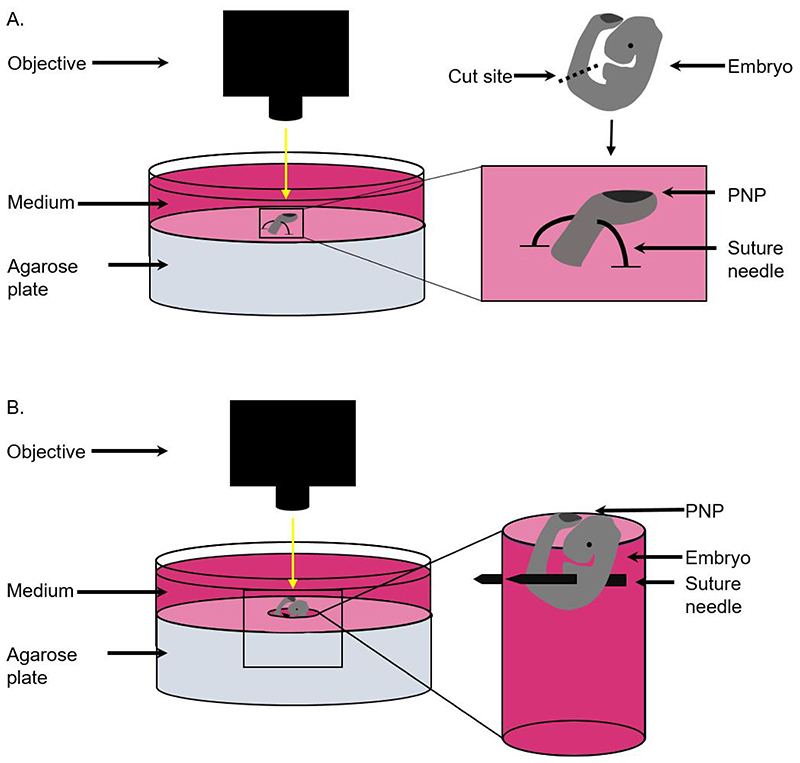
Separate the caudal from the rostral half of the embryo (Figure 1a) and discard the latter or use it for genotyping. This is to remove the effect of the beating heart, which causes too much movement to accurately ablate single cell borders.
Position the caudal region by piercing a curved suture needle through the most ventral part of the tissue (Note 6), ensuring the PNP is pointing upwards. As a guide, aim to insert the needle below the level of the somites (Figure 1a, Note 7), ensuring the neuroepithelium and dorsal surface ectoderm are not touched.
Fix both ends of the needle in the agarose (Figure 1a). This is to ensure there are no sharp metal tips pointing towards the objective.
Figure 1. Schematic to demonstrate positioning of embryos for single cell and tissue laser ablation.
A) For single cell ablations, the caudal region of the embryo is cut using forceps and positioned by piercing the ventral half of the tissue using a curved suture needle. The tissue is then held in place with both ends of the suture needle fixed in the agarose. B) For tissue level ablation, whole embryos are positioned by creating a hole in the agarose and piercing the embryo through the body to the walls of the hole using a suture needle.
3.3.2. Embryo positioning for tissue-level ablations
Use an agarose plate with a central hole and fill it with pre-warmed dissection medium.
After removing the extraembryonic membranes, transfer the embryo to the agarose plate and guide it into the hole (Note 8).
Pin a suture needle dorsal to the heart and into the side of the hole. The embryo should be oriented so that the PNP is visible above the surface of the agarose (Figure 1b). The heart beat should continue steadily throughout the experiment.
If the heart beat interferes with imaging, additional needles can be added to support and stabilise the caudal part of the embryo (Note 9).
3.4.0. Imaging and ablation settings
The imaging and ablation settings need to be optimised for the equipment used. Those described here achieve the desired objectives in our hands. Carefully transfer the agarose dish with the embryo pinned on it into the microscope incubation chamber and place it into an appropriate stage inset, ensuring it does not wobble. Find the part of the embryo to be ablated and continue with the steps below, which are modified for each type of ablation.
3.4.1. Cell border ablations
Image CellMask stained live embryo cell borders with a 20X dipping objective using the 633 nm wavelength, at maximums can speed without averaging. Identify a cell border to ablate and rotate the sample so that border is along the Y axis, such that the laser travels along the X axis (faster).
Zoom in 4x (0.1 x 0.1 μm x/y pixel size, Note 10) and adjust the Z-plane so the border signal is clear in the plane of view. Be careful when focusing to avoid contact between the objective and the embryo/ needle.
Using the microscope (ZEN) software in continuous imaging mode, draw a Region Of Interest (ROI) as a 0.1 μm wide line, which does not overlay other cell borders.
To perform an ablation, adjust the MaiTai multiphoton laser to 710 nm, 80% laser power, 0.34 μs pixel dwell time for 20 iterations. In our hands, these settings reliably ablate superficial cell borders without producing an air bubble.
Image the field of view before and immediately after ablation. You can re-image repeatedly after ablation to generate kymographs of border movement over time.
Only one ablation is analysed per embryo to avoid potential confounding effects of local reactions on nearby cells, although multiple ablations could potentially be performed in different regions.
3.4.2. Tissue-level ablations
For tissue ablations, PNPs are imaged using a 10X dipping objective and reflection mode imaging at 633 nm with a MBS T80/R20 beam splitter (4).
Acquire a pre-ablation Z-stack of the PNP. For embryonic day 9.5 embryos, 150-200 slices of 1.4 μm Z-step are required to go through the whole tissue. With these settings, total acquisition time for each stack is <3 min.
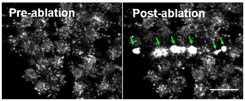
Without changing embryo positioning, adjust the MaiTai multiphoton laser to 800 nm, 100% laser power, 65.94 μs pixel dwell time for 1 iteration. These settings are used to study tissue-level deformation away from the site of ablation as they can produce air bubbles (Figure 4), which are often helpful in ensuring the tissue has been mechanically disrupted.
Using the microscope software, draw a narrow (~2 μm) rectangular ROI ~300-500 μm long along the most recently fused portion of the neural tube.
Ablate the ROI, moving sequentially along the Z (dorso-ventral) axis and re-ablating until the full volume of tissue within the ROI has been ablated.
Immediately after ablation, reload the pre-ablation image acquisition settings and capture a post-ablation z-stack.
Figure 4. Air bubbles (arrows) produced following laser ablation.
These bubbles are visible as brightly reflective surfaces on reflection imaging as shown here. They can also be seen under a stereomicroscope and can be dislodged, causing them to float off the tissue. Bubble formation precludes analysis of cell border recoil adjacent to them. Scale bar = 20 μm.
3.5.0. Image analysis
In all cases, recoil away from the ablation can be calculated by measuring the immediate displacement of cell landmarks perpendicular to the ablation. All images can be analysed using the image analysis software FIJI and in-built plugins (25).
3.5.1. Cell border ablations
Using rigid body registration in the StackReg plugin (26), correct the acquired sequence for any tissue-level drift movement.
Identify a reference point on either side of the ablation (for example cell protrusions, thicker parts of the cell membrane, cell-cell junctions). These reference points need to be visible in both frames.
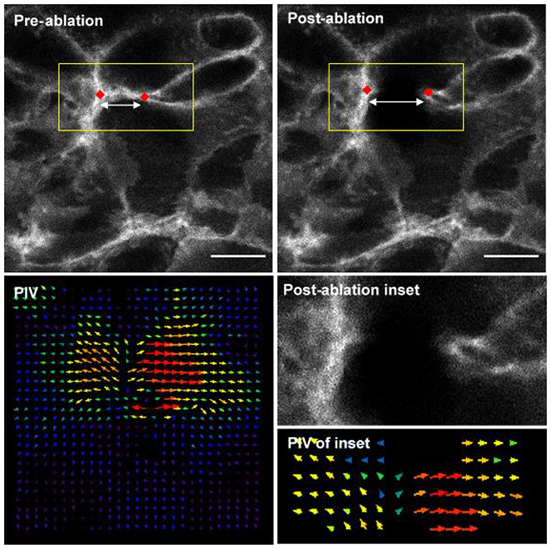
Draw a line connecting the two points in frame 2 and 3 and measure the length of each line in μm. The difference in length of the two lines is the recoil and is a readout of the tension the cell had been withstanding (Notes 11, 12).
Cell-level deformation can be visualised using Fiji’s inbuilt tools such as particle image velocimetry (PIV, Figure 2) (27).
Figure 2. Representative single cell border laser ablation of surface ectoderm rostral to the mouse PNP.
The distance between two reference points (red diamonds) can be compared before and after ablation as a measure of initial recoil. Particle Image Velocimetry (PIV) reveals the extent of movement in the regions around the border. Direction of arrows represent direction of pixel movement. Length and size of arrows represents magnitude of movement. Scale bars = 10 μm.
3.5.2. Tissue-level ablations
Correct the orientation of the PNP in both the pre- and post- ablation z stacks, by reslicing in Y and Z.
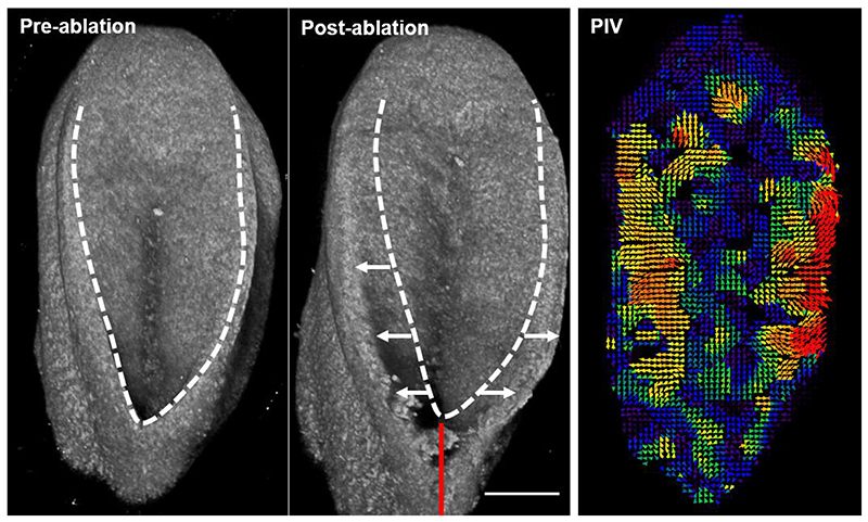
Concatenate the pre- and post- ablation stacks and use the correct 3D drift plugin (28) to correct for any movement. Create a maximum z projection to confirm that registration was successful (Figure 3, Note 13).
Re-slice the concatenated sequence in Z. Go through the resliced sequence and select the frame where the zippering point is visible. Duplicate the frames in both time points so there is one frame for pre- and one for post-ablation.
Identify two reference points on either side of the open neural tube caudal to the ablation site and calculate the recoil as described above.
Tissue-level deformation can be analysed using PIV or previously-published workflows such as the Tissue Deformation and Strain Measurement script, and it may be informative to measure recoil sequentially along the length of the PNP away from the ablation site (4).
Figure 3. 3D projections of representative tissue-level ablation rostral to the mouse PNP fusion point.
The caudal end of the embryo is at the top of the image. The dashed line indicates the outline of the PNP before ablation, white arrows indicate PNP widening due to lateral tissue recoil and the red line indicates the ablated region. Recoil magnitude varies between genotypes and developmental stages (20). PIV analysis enables visualisation of PNP deformation several hundred microns caudal to the ablation site as previously reported (4). Scale bar = 100 μm.
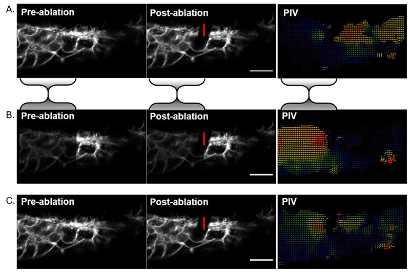
Figure 5. Asymmetrical image brightness alters intensity-based registration output.
A) Cell-level laser ablation registered using rigid body registration. The bulk of the signal is on the left of the image so registration reduces apparent displacement in that portion relative to the right side of the image. This makes it look like the post-ablation recoil was directionally biased to the right in the PIV analysis. B) As an illustrative example, image intensity was halved in the region bounded by the shaded brackets and rigid body registration was repeated. Now the right side of the image is brighter, so its apparent deformation is minimised at the expense of greater discrepancy on the left. PIV shows leftward bias. C) Intensity-independent landmark-based registration suggests the recoil is symmetrical and largely restricted to the region surrounding the ablation. Vertical red lines indicate the ablated border, scale bars = 20 μm.
Notes
Do not use low melting point agarose. When cooled, the gel should be stiff enough to keep a needle upright when pinned into it even at 37°C.
The advantage of using vital cell dyes to visualise cell borders is that embryos do not need to express fluorescent transgenic markers, although such markers may be preferable, if available. We have also stained cell membranes with conjugated wheat germ agglutinin, and other stains may also work. Do not mix CellMask with other vital dyes such as Hoechst as it may precipitate.
We kill all mice using cervical dislocation. While CO2 euthanasia is preferred in many establishments, we have not validated whether the resulting maternal respiratory acidosis has any effects on the embryo.
In order to minimise the risk of secondary changes, embryos are kept warm throughout and we aim to ablate all embryos in the litter within 1.5 hours of killing the dam.
Ideally, have two people in place for these experiments. One person dissects and positions each embryo while the other images and ablates. Once skilled, two people can easily ablate 12 embryos in an hour.
Handling microsurgical needles with watchmaker forceps requires practice. If the needles are pinched at the wrong angle they can ping off the forceps. Handle them with a pair of blunt forceps with broad, flat ends which give you more contact surface than fine-tipped dissection forceps. Providing they are not lost, the same needles can be reused for several years.
Positioning this delicate tissue requires considerable dexterity, yet must be done quickly. Consider practicing on fixed embryos first, then on live embryos and stain them with propidium iodide to confirm cells in your region of interest have not been damaged.
The hole cut in the agarose plate serves two purposes: it gives you a landmark to ensure your embryo is central in the dish and stops the embryo’s head rotating down once pinned. Although the pin in Figure 1b is shown as being straight for simplicity, those specified in the materials section are curved, which facilitates positioning.
We consider the heart beat a desirable indicator of embryo viability which also has the potential to influence embryo hydrostatic properties and tissue-level mechanics. If the embryo becomes unhealthy, for example due to incorrect buffer pH or thermostat malfunction, cellular blebbing becomes apparent and the experiment should cease.
The smaller the field of view, the faster the image can be acquired and cell border recoil should continue for a few seconds after the post-ablation image. Only the first post-ablation image is used to quantify initial recoil, but it is commonplace to show kymographs of recoil over time. Image settings must be kept identical for embryos intended to be compared.
The end point of this analysis is a recoil length, not velocity. Frame acquisition rate is the same between samples, so we report the measured parameter rather than calculating velocity (recoil distance divided by time). Landmarks chosen across the ablated border must be perpendicular to the ablation and should be as close together as possible.
The reproducibility with which changes in length between landmarks are measured improves with imaging quality and analysis experience. It is entirely appropriate to re-measure recoil for each sample multiple times and take an average. Analysis of recoil should be performed blinded to experimental conditions.
Most registration algorithms are based on image intensity. This means that if one half of the image is brighter, registration will be biased towards reducing movement in that region. Be careful not to over-interpret directionality in registered images (Figure 5).
References
- 1.Nikolopoulou E, Galea GL, Rolo A, Greene ND, Copp AJ. Neural tube closure: cellular, molecular and biomechanical mechanisms. Development. 2017;144:552–566. doi: 10.1242/dev.145904. [DOI] [PMC free article] [PubMed] [Google Scholar]
- 2.Vijayraghavan DS, Davidson LA. Mechanics of neurulation: From classical to current perspectives on the physical mechanics that shape, fold, and form the neural tube. Birth Defects Res. 2017;109:153–168. doi: 10.1002/bdra.23557. [DOI] [PMC free article] [PubMed] [Google Scholar]
- 3.Butler MB, et al. Rho kinase-dependent apical constriction counteracts M-phase apical expansion to enable mouse neural tube closure. J Cell Sci. 2019;132 doi: 10.1242/jcs.230300. [DOI] [PMC free article] [PubMed] [Google Scholar]
- 4.Galea GL, et al. Biomechanical coupling facilitates spinal neural tube closure in mouse embryos. Proc Natl Acad Sci U S A. 2017;114:E5177–E5186. doi: 10.1073/pnas.1700934114. [DOI] [PMC free article] [PubMed] [Google Scholar]
- 5.Zulueta-Coarasa T, Fernandez-Gonzalez R. Tension (re)builds: Biophysical mechanisms of embryonic wound repair. Mech Dev. 2017;144:43–52. doi: 10.1016/j.mod.2016.11.004. [DOI] [PubMed] [Google Scholar]
- 6.Hutson MS, et al. Combining laser microsurgery and finite element modeling to assess cell-level epithelial mechanics. Biophys J. 2009;97:3075–3085. doi: 10.1016/j.bpj.2009.09.034. [DOI] [PMC free article] [PubMed] [Google Scholar]
- 7.De Pascalis C, Etienne-Manneville S. Single and collective cell migration: the mechanics of adhesions. Mol Biol Cell. 2017;28:1833–1846. doi: 10.1091/mbc.E17-03-0134. [DOI] [PMC free article] [PubMed] [Google Scholar]
- 8.Cooke J. Control of somite number during morphogenesis of a vertebrate, Xenopus laevis. Nature. 1975;254:196–199. doi: 10.1038/254196a0. [DOI] [PubMed] [Google Scholar]
- 9.Beloussov LV, Dorfman JG, Cherdantzev VG. Mechanical stresses and morphological patterns in amphibian embryos. J Embryol Exp Morphol. 1975;34:559–574. [PubMed] [Google Scholar]
- 10.Panousopoulou E, Green JB. Invagination of Ectodermal Placodes Is Driven by Cell Intercalation-Mediated Contraction of the Suprabasal Tissue Canopy. PLoS Biol. 2016;14:e1002405. doi: 10.1371/journal.pbio.1002405. [DOI] [PMC free article] [PubMed] [Google Scholar]
- 11.Tsai PS, et al. Plasma-mediated ablation: an optical tool for submicrometer surgery on neuronal and vascular systems. Curr Opin Biotechnol. 2009;20:90–99. doi: 10.1016/j.copbio.2009.02.003. [DOI] [PMC free article] [PubMed] [Google Scholar]
- 12.Vogel A, Venugopalan V. Mechanisms of pulsed laser ablation of biological tissues. Chem Rev. 2003;103:577–644. doi: 10.1021/cr010379n. [DOI] [PubMed] [Google Scholar]
- 13.Smutny M, Behrndt M, Campinho P, Ruprecht V, Heisenberg CP. UV laser ablation to measure cell and tissue-generated forces in the zebrafish embryo in vivo and ex vivo. Methods Mol Biol. 2015;1189:219–235. doi: 10.1007/978-1-4939-1164-6_15. [DOI] [PubMed] [Google Scholar]
- 14.Kiehart DP, Galbraith CG, Edwards KA, Rickoll WL, Montague RA. Multiple forces contribute to cell sheet morphogenesis for dorsal closure in Drosophila. J Cell Biol. 2000;149:471–490. doi: 10.1083/jcb.149.2.471. [DOI] [PMC free article] [PubMed] [Google Scholar]
- 15.Farhadifar R, Roper JC, Aigouy B, Eaton S, Julicher F. The influence of cell mechanics, cell-cell interactions, and proliferation on epithelial packing. Curr Biol. 2007;17:2095–2104. doi: 10.1016/j.cub.2007.11.049. [DOI] [PubMed] [Google Scholar]
- 16.Liang X, Michael M, Gomez GA. Measurement of Mechanical Tension at Cell-cell Junctions Using Two-photon Laser Ablation. Bio Protoc. 2016;6 doi: 10.21769/BioProtoc.2068. [DOI] [PMC free article] [PubMed] [Google Scholar]
- 17.Angelo JR, Tremblay KD. Laser-mediated cell ablation during post-implantation mouse development. Dev Dyn. 2013;242:1202–1209. doi: 10.1002/dvdy.24017. [DOI] [PMC free article] [PubMed] [Google Scholar]
- 18.Petridou NI, Heisenberg CP. Tissue rheology in embryonic organization. EMBO J. 2019;38:e102497. doi: 10.15252/embj.2019102497. [DOI] [PMC free article] [PubMed] [Google Scholar]
- 19.Sugimura K, Lenne PF, Graner F. Measuring forces and stresses in situ in living tissues. Development. 2016;143:186–196. doi: 10.1242/dev.119776. [DOI] [PubMed] [Google Scholar]
- 20.Galea GL, et al. Vangl2 disruption alters the biomechanics of late spinal neurulation leading to spina bifida in mouse embryos. Dis Model Mech. 2018;11 doi: 10.1242/dmm.032219. [DOI] [PMC free article] [PubMed] [Google Scholar]
- 21.Hughes A, Greene NDE, Copp AJ, Galea GL. Valproic acid disrupts the biomechanics of late spinal neural tube closure in mouse embryos. Mech Dev. 2018;149:20–26. doi: 10.1016/j.mod.2017.12.001. [DOI] [PMC free article] [PubMed] [Google Scholar]
- 22.Nikolopoulou E, et al. Spinal neural tube closure depends on regulation of surface ectoderm identity and biomechanics by Grhl2. Nat Commun. 2019;10:2487. doi: 10.1038/s41467-019-10164-6. [DOI] [PMC free article] [PubMed] [Google Scholar]
- 23.Mole MA, et al. Integrin-Mediated Focal Anchorage Drives Epithelial Zippering during Mouse Neural Tube Closure. Dev Cell. 2020;52:321–334.:e326. doi: 10.1016/j.devcel.2020.01.012. [DOI] [PMC free article] [PubMed] [Google Scholar]
- 24.Pryor SE, Massa V, Savery D, Greene ND, Copp AJ. Convergent extension analysis in mouse whole embryo culture. Methods Mol Biol. 2012;839:133–146. doi: 10.1007/978-1-61779-510-7_11. [DOI] [PMC free article] [PubMed] [Google Scholar]
- 25.Schindelin J, et al. Fiji: an open-source platform for biological-image analysis. Nat Methods. 2012;9:676–682. doi: 10.1038/nmeth.2019. [DOI] [PMC free article] [PubMed] [Google Scholar]
- 26.Thevenaz P, Ruttimann UE, Unser M. A pyramid approach to subpixel registration based on intensity. IEEE Trans Image Process. 1998;7:27–41. doi: 10.1109/83.650848. [DOI] [PubMed] [Google Scholar]
- 27.Tseng Q, et al. Spatial organization of the extracellular matrix regulates cell-cell junction positioning. Proc Natl Acad Sci U S A. 2012;109:1506–1511. doi: 10.1073/pnas.1106377109. [DOI] [PMC free article] [PubMed] [Google Scholar]
- 28.Parslow A, Cardona A, Bryson-Richardson RJ. Sample drift correction following 4D confocal time-lapse imaging. J Vis Exp. 2014 doi: 10.3791/51086. [DOI] [PMC free article] [PubMed] [Google Scholar]


