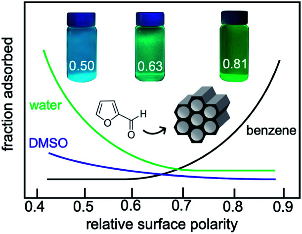
 Adsorption of organic molecules from solution into mesoporous organosilicas is modulated by the relative polarity of the surface.
Abstract
Surface polarity plays a key role in controlling molecular adsorption at solid–liquid interfaces, with major implications for reactions and separations. In this study, the chemical composition of periodic mesoporous organosilicas (PMOs) was varied by co-condensing Si(OEt)4 with organodisilanes, to create a homologous series of materials with similar surface areas, pore volumes, and hydroxyl contents. Their relative surface polarities, obtained by measuring the fluorescence of a solvatochromic dye, cover a wide range. In this series of PMO materials, EPR spectra of tethered nitroxide radicals show monotonically decreasing mobility as larger fractions of the radicals interact strongly with increasingly non-polar surfaces. The surface properties of the materials also correlate with their affinities for organic molecules dissolved in various solvents. The most polar PMO has negligible affinity for phenol, p-cresol, or furfural when these molecules are dissolved in water. However, stronger solute–surface interactions and favor adsorption as the surface polarity decreases. The trend is reversed for furfural in benzene, where weaker solvent–surface interactions result in higher adsorption on polar surfaces. In DMSO, furfural adsorption is suppressed due to the similar strengths of solute-surface and solvent–surface interactions. Thus, the polarity of the surface relative to the solvent is critical for molecular adsorption. These findings show how adsorption/desorption can be precisely and systematically tuned by appropriate choice of both solvent and surface, and contribute to a predictive strategy for the design of catalytic and separations processes.
Introduction
Modulating the polarity of the condensed phase environment by the choice of solvent is a promising strategy to improve the efficiency of emerging energy technologies such as the valorization of biomass, by increasing the activity and selectivity of the catalyst.1–3 For example, the yield of levulinic acid from the acid-catalyzed dehydration of mono- and oligosaccharides is highest in water compared to THF or toluene, since oligomerization side-reactions are suppressed by better solvation of sugars and their dehydration products in the aqueous solution.4 The polarity of an aqueous reaction medium can also be modified by adding co-solvents or salts.5,6
In heterogeneous catalysis, surface polarity can influence catalytic activity by altering the adsorption of molecules at or near the active sites, as well as the activation barriers for reactions at those sites. Thus, Pd nanoparticles supported on a hydrophilic zeolite showed higher activity in furfural conversion and higher selectivity to furan compared to Pd on a hydrophobic zeolite, due to the increased affinity of the polar catalyst support for the reactant relative to the product.7 Although the surface polarity can be changed by modifying the chemical composition of the catalyst,1,2,8 other influential characteristics such as textural properties, the extent of confinement, the number of active sites, and even their identity, can also be affected. The assessment of correlations between surface polarity and catalytic properties is complicated in such cases. For example, the number of strong Brønsted acid sites increases in parallel with surface polarity in zeolites, and in ZrO2.9,10 It is desirable to tune the polarity of the catalyst precisely and independently.
Some catalyst support materials, such as silicas and carbons, are readily modified post-synthesis with varying types and loadings of chemically distinct components.7,11,12 For example, hydrocarbon chains with or without functional groups can be anchored in the pores of periodically-ordered mesoporous silicas (e.g., MCM-41, SBA-15).13,14 However, other synthesis methods do not allow independent control of polarity and textural properties.7,14,15 Co-condensation is a powerful strategy to separate these effects, since two or more different types of (organo)silane precursors can be incorporated in varying amounts, while controlling the morphology through the use of a templating agent.16 Nevertheless, differences in condensation rates can cause significant changes in surface area and/or pore volume, and increase variability in the series of target materials.17,18 In addition, the spatial distribution of the co-condensed organosilanes may be non-random.19
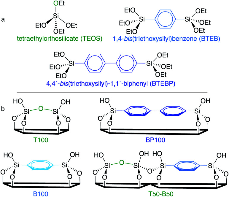
In this work, we synthesized a family of periodic mesoporous organosilicas (PMOs) by co-condensing an inorganic silica source with varying amounts of two organodisilanes (Scheme 1). The resulting hybrid SBA-15-type materials have similar meso- and macrostructures, surface areas and pore volumes, but gradually changing chemical compositions.
Scheme 1. (a) Chemical structures of three silica precursors used in this work, and (b) the surface compositions of some of the resulting SBA-15-type materials.
Relating the effect of compositional changes to adsorption requires a method to quantify surface polarity. While contact-angle measurements and water vapor adsorption isotherms correlate with surface polarity,7,20,21 their interpretation is not straightforward for porous materials or rough surfaces. Instead, we assessed the polarity of each PMO by comparing the fluorescence of an adsorbed solvatochromic dye, Prodan, with its fluorescence in various solvents of known polarity. This technique has been used to estimate the interfacial polarity of MCM-41-type materials with functionalized pore surfaces.13 We also used EPR lineshape analysis to assess changes in the mobility of TEMPO (2,2,6,6-tetramethylpiperidinyloxy) spin labels covalently attached to and interacting with PMO surfaces.22,23 Finally, we explored how the affinity of these materials for representative organic molecules relevant to the upgrading of lignocellulosic biomass is controlled by surface and solvent polarity.
Experimental section
Chemicals
Tetraethylorthosilicate (TEOS, 98%), 1,4-bis(triethoxysilyl)benzene (BTEB, 96%), 4,4′-bis(triethoxysilyl)1-1′-biphenyl (BTEBP, 95%), Pluronic P123, p-cresol (99%), phenol (99%), furfural (99%), anisole (>99%), vanadium oxytrichloride (99%), N-(3-dimethylaminopropyl)-N-ethylcarbodiimide hydrochloride, and N,N-dimethyl-6-propionyl-2-naphthylamine (Prodan) were purchased from Sigma Aldrich. 4-Carboxy–TEMPO and 3-aminopropyldimethylethoxysilane were purchased from Santa Cruz Biotechnology and Gelest, Inc., respectively. Deuterium oxide (99.9%), dimethylsulfoxide-d6 (99.9%) and benzene-d6 (99.5%) were obtained from Cambridge Isotope Laboratories, Inc. All chemicals were used as-received.
Synthesis of PMOs based on TEOS, BTEB, and their mixtures (i.e., T100, B100, and intermediate compositions)
To create a homologous series of porous materials with similar textural properties, we prepared all materials by adapting a literature procedure for the synthesis of SBA-15.24 Pluronic P123 (3.0 g) was dissolved with a stirring in 0.2 M aqueous HCl (106 mL) overnight in a tightly sealed glass flask. The solution temperature was lowered to ∼2 °C with an ice bath. TEOS (30 mmol, 6.68 mL) was added dropwise at a rate of ca. 1 mL min–1 while stirring at 150 rpm. After 1 h, the solution was heated to 40 °C in a water bath and stirred for 23 h. The reaction mixture was transferred to a Parr pressure reactor equipped with a Teflon liner (125 mL). After heating in an oven at 100 °C for 48 h, the resulting suspension was filtered and washed with ∼500 mL water, then dried overnight in air at 100 °C. Residual P123 was removed by ethanol Soxhlet extraction at 110 °C for 24 h. Next, the material was dried at 70 °C in air for 12 h to remove ethanol. Residual P123 was eliminated by calcination at 250 °C in air for 3 h. Organic groups in the framework are expected to be unaffected at this temperature,25 confirmed by TGA (Fig. S1†).
The synthesis procedure must be adjusted to prepare the organosilicas. In general, fully siliceous SBA-15 is synthesized under acidic conditions, with HCl concentrations in the range 1.5–2.0 M (corresponding to a HCl : H2O molar ratio of ca. 0.03). However, when BTEB was injected in this pH range, the hydrothermal reaction at 40 °C for 24 h gave a dense white precipitate and a semi-transparent gel. Since the hydrolysis of the organodisilane is much faster than that of TEOS,26–28 the organosilane condensed rapidly without sufficient interaction with P123, resulting in a poorly ordered structure. The XRD pattern of the powder recovered from the white precipitate lacks the (110) and (220) reflections characteristic of long-range mesopore ordering. A lower HCl : H2O molar ratio (between 10–3 and 10–4) is known to retard the hydrolysis/condensation of the organosilane, although mesoscale ordering is not greatly affected until the isoelectric point (pH ∼ 2) is reached.27,28 Therefore a ten-fold smaller HCl concentration, 0.2 M, was used to prepare the phenylene-bridged organosilica material.
PMO frameworks containing various fractions of phenylene bridging groups were synthesized using mixtures of TEOS and BTEB, adjusting the relative amounts of the precursors as shown in Table S1† to ensure mesostructure formation. The appropriate ratio is determined by the interaction strengths of each silane with P123. The materials are named according to the type(s) of silane precursors (T: TEOS; B: BTEB; BP: BTEBP) and their relative proportions. For example, T50-B50 was synthesized using 50 mol% TEOS and 50 mol% BTEB as silica precursors. The extent of incorporation of each silane was confirmed by thermogravimetric analysis (TGA) to be similar to the composition of the corresponding synthesis mixture (Fig. S1†).
Synthesis of BTEBP-containing PMOs
Well-ordered B75-BP25 was made following the procedure described above, by co-condensing 5.5 mmol BTEB with 1.8 mmol BTEBP. However, the same reaction conditions did not lead to mesophase formation in the fully biphenylene-bridged PMO (BP100). Therefore, BP100 was synthesized using 1-butanol29,30 as a co-surfactant with P123, following the method described by Yang et al.31 First, P123 was dissolved in acidic aqueous solution (0.5 M HCl, 106 mL), then 1-butanol (11 mmol) was added at room temperature. After stirring for 1 h, BTEBP (6.5 mmol) was added and the solution temperature was increased to 40 °C. After 24 h, the reaction mixture was transferred to a Parr pressure reactor (125 mL), where it was aged at 100 °C for 48 h. The surfactant was removed following the procedure described above.
Materials characterization
Powder X-ray diffraction patterns were acquired from 0.5 to 3.0° [2θ], and from 5 to 40° [2θ], using a Rigaku X-ray diffractometer equipped with Cu Kα radiation. N2 sorption isotherms were measured at 77 K using 3 Flex Micrometrics equipment. Before measurement, each material was outgassed at 423 K for 8 h in flowing N2 to remove physically adsorbed water. The apparent surface area was calculated using the Brunauer–Emmett–Teller (B.E.T.) equation, assuming a molecular area of 0.135 nm2 for adsorbed N2.32 The total pore volume was obtained from the amount of adsorbed N2 measured at P/P0 = 0.99. The average pore diameter was calculated by analyzing the adsorption branch of the N2 isotherm, using the Barret–Joyner–Halenda (B.J.H.) method. 13C CP-MAS NMR spectra were acquired at room temperature on a 500 MHz WB Bruker Avance NMR Spectrometer, in an 11.7 T magnetic field. TGA measurements were performed in air with a TA Discovery Thermo-Gravimetric Analyzer in the temperature range from 50 to 720 °C (10 °C min–1).
Silanol group quantification
The number of accessible surface silanol groups was determined via their reaction with VOCl3.33 A Schlenk flask containing a PMO sample (ca. 40 mg) was evacuated at 0.1 mTorr and 170 °C for 7 h to remove physisorbed water, whose absence from the dry PMO was confirmed by IR. Excess VOCl3 vapor (ca. 1 mmol) was transferred under reduced pressure at room temperature and allowed to react for 30 min. The chemisorbed vanadium was extracted from a precisely weighed sample (approx. 10 mg) by stirring in 5 mL of 1 M H2SO4 solution containing H2O2 (0.26 M).33 The resulting solution contains a mixture of red-brown mono- and bis(peroxo)vanadium(v) complexes. The absorbance, measured at 448 nm using a Shimadzu UV-2401 UV-vis spectrophotometer, was compared to a calibration curve prepared using ammonium vanadate under same experimental conditions. The calculation of vanadium content was corrected for the change in PMO mass caused by modification with VOCl3 as follows: for x mg V-modified PMO, and a measured vanadium concentration in the solution of y mmol mL–1, the amount z of unmodified PMO present in the analysis solution (mg mL–1) is z = (x/5) – 136.8y, where 136.8 mg mmol–1 is the difference in molecular weight between [VOCl2] and the proton it replaces. Since the vanadium content is equal to the number of accessible silanols,33 the SiOH surface density (αOH) is y/z mmol mg–1.
Fluorescence measurements
An aqueous solution of Prodan (15 μM) was prepared by vigorous stirring at room temperature for 6 h. Each PMO (20 mg) was stirred with 15 mL Prodan solution for 10 h, then centrifuged at 3000 rpm for 15 min. The supernatant liquid was decanted and the solid was dried at 100 °C for 6 h in air. Emission spectra for the dry powders were recorded with a Horiba FluoroMax 4 spectrometer, using an excitation wavelength of 365 nm. The peak maximum λmax was identified as the zero-crossing of the first-derivative. Spectra were also acquired for each PMO powder dispersed in water. For both types of measurement, relative polarity values were interpolated using the correlation between relative polarity34 and λmax reported for Prodan dissolved in various solvents,35 fitted using a second-order polynomial function.
EPR spectroscopy
For selected PMOs, a small fraction (ca. 1%) of surface silanols were modified with TEMPO (the spin label), using the coupling reaction between tethered propylamine and carboxy-substituted TEMPO, following a slightly modified literature procedure.36,37 Each PMO (20 mg) was suspended in phosphate buffered saline solution (pH 7.4, 2 mL), then 3-aminopropyldimethylethoxysilane (APDMES, 16 μL) was added and the mixture was stirred for 18 h at room temperature. The solid was separated by centrifugation and combined with 4-carboxy-TEMPO (0.5 mL, 10 mM in 2-morpholin-4-ylethanesulfonic (MES) acid buffer, pH 4.5) and N-(3-dimethylaminopropyl)-N-ethylcarbodiimide hydrochloride (1.2 mL, 50 mM in pH 4.5 MES buffer).
After 48 h incubation at room temperature, the mixture was centrifuged at 3000 rpm for 4 min. (Previously, a much shorter reaction time, 30 min, was reported for TEMPO functionalization of amine-modified non-porous silicas.37 We observed that this procedure leads to partial peptide bond cleavage, possibly catalyzed by residual unreacted propylamine groups during the subsequent EPR measurement. Extending the reaction time prevents complication of the EPR spectra by contributions from untethered radicals.) The supernatant liquid was removed and the solid was resuspended in DI water. This step was repeated 10 times to ensure complete removal of unreacted 4-carboxy-TEMPO, as judged by the absence of EPR signals for the untethered radical. No signals for untethered radicals reappeared for the duration of the EPR measurement (ca. 6 h).
The spin-labeled material (ca. 4 μL of a PMO slurry, 40 mg mL–1) was placed in a quartz capillary (0.60 mm I.D., 0.84 mm O.D.). X-band continuous-wave (CW) EPR spectra were recorded on a Bruker EMSplus EPR spectrometer, using a Bruker ER 4119HS-LC high sensitivity resonator at a microwave frequency of ca. 9.3 GHz, with 1 mW irradiation power and 0.4 G modulation width. Spectra were simulated by lineshape fitting using the SimLabel software,38 which relies on the same functions as EasySpin.39
Quantitative adsorption measurements
Each PMO (20 mg) was mixed with a solution containing the desired amount of p-cresol, phenol, or furfural (dissolved in 1.5 mL of the specified deuterated solvent) in a 2 mL centrifuge tube. The slurry was agitated in an IKA Vortex 4 digital mixer at 3000 rpm for 10 h, then centrifuged at 3000 rpm for 8 min to separate the solid. The decanted supernatant was analyzed by solution-state 1H NMR (Varian Unity, 500 MHz), using DMSO as an internal standard. When organic molecules were adsorbed directly from DMSO-d6, the residual solvent peak was used as the standard instead.
Results and discussion
Synthesis and characterization of periodic mesoporous organosilicas (PMOs)
A series of SBA-15-type PMOs was synthesized with uniform morphologies and a range of surface chemical compositions. Three different silanes: tetraethylorthosilicate (TEOS), 1,4-bis(triethoxysilyl)-benzene (BTEB), and 4,4′-bis(triethoxysilyl)-1,1′-biphenyl (BTEBP), were chosen for incorporation in various ratios into the ordered mesoporous SBA-15 framework (Scheme 1a). The fully inorganic TEOS-based material (T100) is expected to have the most polar surface, while the BTEBP-based PMO (BP100) should be the least polar due to its bridging biphenylene groups, Scheme 1b. Intermediate surface polarities are expected for the BTEB-based material (B100), and for co-condensed mixtures of TEOS/BTEB, or BTEB/BTEBP.
SEM images for the PMOs show elongated fibers with diameters of 0.3–0.6 μm and lengths of 2–10 μm (Fig. S2†), consistent with previous studies.24,25 However, BP100 has a distinctive, particulate structure. The incorporation of phenylene and/or biphenylene-bridged groups into the organosilica framework was confirmed by 13C solid-state CP/MAS NMR of selected materials (Fig. S3†). Small- and wide-angle XRD patterns for the various PMOs were recorded after surfactant removal. For all materials except BP100, the appearance of clear d110 and d220 reflections in the low-angle region is evidence for mesopores with a high degree of long-range order. The positions of these d100 reflections are similar for all materials (Fig. S4†), although the displacement of the peak for T100 indicates a slight increase in the unit cell size (from ca. 120 to 130 Å). The wide-angle XRD patterns of B100 and BP100 show reflections characteristic of their molecular periodicity (Fig. S5†).
The small-angle XRD pattern of BP100, whose synthesis required the use of a 1-butanol as co-surfactant to achieve mesophase formation, does not contain clear low-angle peaks, implying less uniformity in its mesopores. In addition, BP100 shows significant interparticle porosity, reflected in a hysteresis loop that extends to very high relative pressures (Fig. S6a†).31 The pore size distribution is significantly broader than for the other PMOs (Table 1 and Fig. S6b†).
Table 1. Comparison of physicochemical properties of various PMO materials.
| PMO | B.E.T. surface area a (m2 g–1) | Mesopore volume b (cm3 g–1) | Pore size c (nm) | Silanol surface density d , αOH (mmol g–1) | OH e per nm2 |
| T100 | 709 | 1.12 | 9.7 ± 0.5 | 2.1 | 1.8 |
| T75-B25 | 668 | 0.99 | 7.6 ± 0.3 | 1.7 | 1.5 |
| T50-B50 | 694 | 1.00 | 7.5 ± 0.7 | 1.7 | 1.5 |
| T25-B75 | 708 | 1.08 | 7.1 ± 0.7 | 2.1 | 1.8 |
| B100 | 721 | 1.08 | 7.7 ± 0.8 | 1.5 | 1.3 |
| B75-BP25 | 719 | 1.01 | 6.3 ± 0.3 | 2.1 | 1.8 |
| BP100 | 728 | 1.18 | 5.0 ± 3.6 | 1.9 | 1.6 |
aCalculated using the Brunauer–Emmett–Teller (B.E.T.) method. The generally accepted measurement error is ±10%.41 The calculations assume an area for adsorbed N2 of 0.135 nm2 per molecule, which is the value appropriate for perpendicular adsorption on oxide surfaces.32 Since N2 adsorbs parallel to the surface on organic materials, occupying a larger area (0.162 nm2), the actual surface areas of the organosilicas may be somewhat higher, but the fractions of parallel vs. perpendicularly adsorbed N2 are not known. Finally, B.E.T. surface areas normalized by mass do not reflect differences in skeletal densities for silicas with different organic fractions.
bMeasured at P/P0 = 0.99, except for BP100, for which P/P0 = 0.95 was used (see Fig. S6).
cCalculated using the Barrett–Joyner–Halenda (B.J.H.) method, using the adsorption branch of the isotherm, and reported as the average pore size and standard deviation.
dThe measurement error associated with these values is estimated to be ±0.1 mmol g–1.
eThe error generated due to the experimental uncertainty in the surface area measurements is ±0.3 nm–2.
The physicochemical properties of all PMOs are compared in Table 1. Their B.E.T. surface areas vary over a relatively small range, from 668 to 728 m2 g–1, as do their B.J.H. pore volumes (0.99 to 1.18 cm3 g–1). Assuming similar wall thicknesses, the slightly higher unit cell size for T100 is consistent with its larger pore size (9.7 nm). Nevertheless, the variability is small compared to materials used in previous comparative studies of surface polarity effects on catalysis (for which reported surface areas, pore sizes or pore volumes varied by factors of 2–4).9,15,40 Thus, the PMOs used in this work appear to be well-suited for isolating the effect of surface polarity on adsorption capacity, while keeping other structural factors mostly constant.
Surface hydroxyl content
Condensation of TEOS and/or organodisilanes, followed by hydrolysis, creates pore surfaces terminated with hydroxyl groups, some of which resist condensation even at very high temperatures.42 Surface polarity is affected by the surface density of these silanols, in addition to the nature and extent of organic content at the interface. The surface silanols present in each PMO were quantified by their reaction with VOCl3.33 The number of VOCl3-accessible surface OH groups is fairly constant, ranging from 1.5 to 2.1 mmol g–1 (1.3–1.8 OH per nm2, Table 1). However, these surface silanol contents are 2–3 times smaller than some previously reported values for SBA-15 (3.5 mmol g–1)43 and MCM-41 (3.6 to 5.3 mmol g–1).43,44 We note that conventional measurement methods count both accessible surface OH groups and inaccessible sub-surface OH groups. A study of the number of such sites that react with trimethylsilyl chloride reported much lower OH contents for SBA-15 and MCM-41 (1.8 and 2.2 mmol g–1, respectively).43 These values are closer to the number of surface OH groups measured here. Thus, SBA-15-type materials synthesized using TEOS, BTEB, and BTEBP precursors have similar numbers of surface silanol groups, and differ significantly only in the type and amount of framework organic groups.
Solvatochromic assessment of gradually varying surface polarity
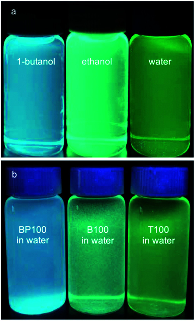
Water affinity (i.e., hydrophilicity) is related indirectly to surface polarity.7,45 For example, water vapor adsorption isotherms were used to obtain qualitative information about the surface wettability of microporous carbons and mesoporous silicas, via comparison of the onset pressures for pore condensation.20,21 However, hydrophilicity and polarity are distinct physical properties. Polarity can be probed more directly using an organic dye such as Prodan, whose electronic energy levels are affected by non-covalent interactions with its surroundings. The wavelength of maximum fluorescence intensity for Prodan depends on the polarity of the solvent in which the dye is dissolved (Fig. 1a). Increasing solvent polarity is associated with a gradual shift in the emission spectrum.11,13,35
Fig. 1. Comparison of Prodan fluorescence: (a) dissolved in the various solvents indicated; and (b) adsorbed on three different PMO materials, all suspended in water.
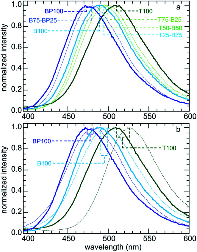
We expect adsorbed Prodan to report on changes in the polarity of PMO surfaces caused by the presence of surface organic groups. Fig. 1b shows the range of emission colors for Prodan adsorbed on three representative PMO powders suspended in water. Emission spectra for Prodan adsorbed on the various dry PMO powders are shown in Fig. 2a. The shortest fluorescence emission wavelength, for BP100 (λmax 473 nm), is consistent with its lower polarity compared to B100 (λmax 489 nm) and T100 (λmax 509 nm, Table S2†). The gradual shift in λmax for intermediate PMO compositions shows that the surface polarity of these materials can be precisely tuned.
Fig. 2. Normalized emission spectra of Prodan: (a) adsorbed on various dry (organo)silica powders; and (b) comparison of selected dry powders (heavier lines) with the same powders suspended in water (lighter lines).
Fluorescence spectra were also recorded for aqueous suspensions of each PMO, following a previously described method.11,13 Fig. 2b compares the spectra for selected materials with those for Prodan adsorbed on the corresponding dry powders. Dispersion of a PMO in water results in a red-shift in the corresponding emission spectrum, consistent with greater surface hydration and hence increased interfacial polarity. However, the magnitude of the shift in λmax is not constant: it is largest (17 nm) for the most polar material (T100), and smallest (9 nm) for the least polar material (BP100). Thus the extent of hydration is higher for the more polar surfaces. This phenomenon, while expected, has implications for adsorption of solutes from aqueous solutions (see below).
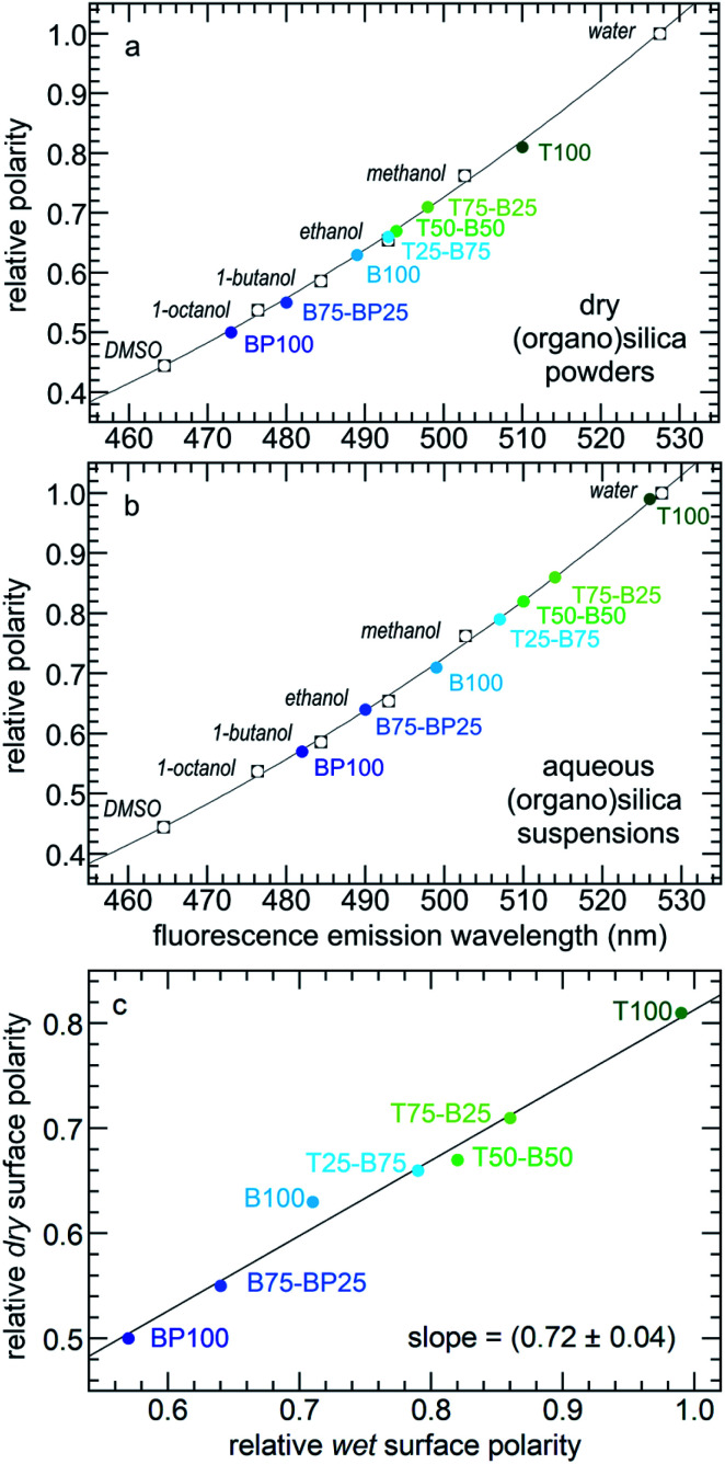
Relative surface polarity values for each PMO were obtained using λmax values for the adsorbed Prodan and interpolating λmax values measured in various solvents of known polarity (Table S3†).35 The results are shown for both dry and wet PMO materials in Fig. 3 and Table S4.† The dry PMO powders have relative surface polarities ranging from 0.50 to 0.81. All values increase when the powders are suspended in water. Thus the relative polarity of dry T100 is similar to that of methanol, while hydrated T100 has a polarity close to that of water. Dry BP100 is less polar than 1-octanol, but wet BP100 has a surface polarity closer to that of 1-butanol. The relationship between pairs of λmax values is linear, although the slope is not unity (Fig. 3c).
Fig. 3. Correlations between the relative polarities of various solvents34 and Prodan fluorescence emission maxima for (a) dry PMO powders, or (b) PMOs suspended in water; and (c) relationship between the relative surface polarities of the dry PMO powders and their aqueous suspensions.
Mobility of adsorbed species
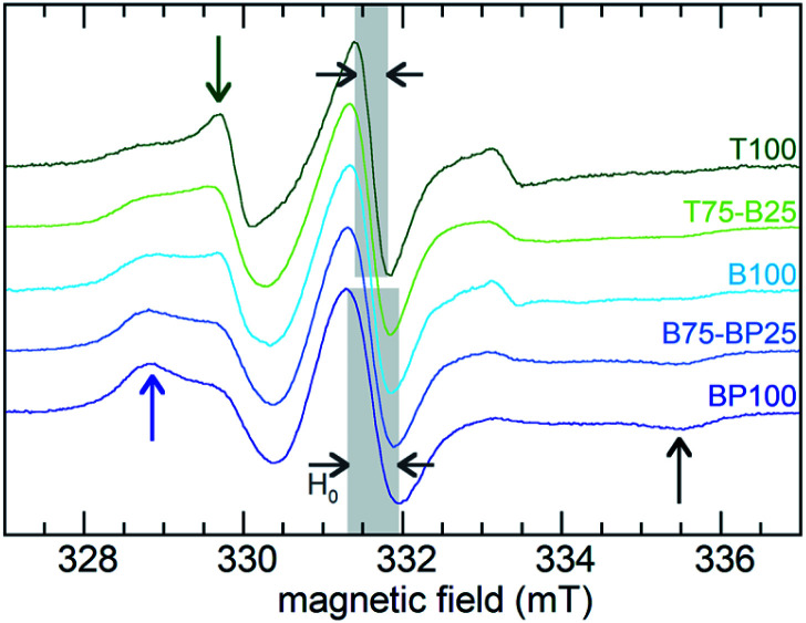
EPR line-shape analysis provides information about the relative mobility of surface-confined spin labels.46–48 It is inversely correlated with the strength of their interaction with the surface. EPR spectra were acquired for TEMPO radicals attached to aminopropylsilane-modified PMOs (Scheme S1†). Low spin concentrations minimize EPR line-broadening effects caused by strong dipolar interactions between neighboring spins,46 therefore only a small fraction (ca. 1%) of surface silanols were functionalized with the nitroxide radical. X-band EPR spectra recorded at room temperature for the spin-labeled PMOs suspended in water are shown in Fig. 4.
Fig. 4. Continuous-wave EPR spectra, recorded at room temperature, for various 4-carboxy-TEMPO-functionalized PMOs suspended in water. Blue and green arrows indicate peaks associated with slower- and faster-moving radicals, respectively. The emergence of a weak peak at high field (black arrow) is also characteristic of an increased fraction of slow-moving radicals.
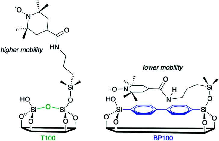
Variations reflect differences in the average local dynamics of the tethered spin-labeled moieties, Scheme 2. Restricted spin motion caused by greater proximity of the tethered radical to the surface results in incomplete averaging of anisotropic terms of the magnetic Hamiltonian. This effect is manifested qualitatively in various types of line broadening and the appearance of distinct spectral features.49,50 First, the line width (H0) of the central peak increases gradually,22,51 from 0.47 to 0.67 mT (grey-shaded region) as the surface polarity decreases from T100 to BP100. The eventual appearance of an outer extremum at 335.5 mT (black arrow) is also a well-established indicator of diminished rotational motion.22,50 In addition, the gradually changing intensities of two partially resolved peaks at 328.8 mT (blue arrow) and 329.7 mT (green arrow) represent varying populations of slow and fast components, respectively. Further line broadening is caused by the increasing fraction of the slow component.
Scheme 2. Two possible orientations of tethered TEMPO spin labels, with different mobilities depending on the extent of their interaction with the PMO surface.
The Azz component of the nitrogen hyperfine tensor element parallel to B0 (i.e., aligned with the z-direction) also varies with local polarity, due to changes in localization of the unpaired electron along the N–O bond axis (perpendicular to the z-axis) modulated by changes in the local electric field.23 In spin-labeled membrane proteins, Azz values were reported to increase from 3.43 to 3.65 mT with increasing polarity of the membrane and the protein micro-environment.23 X-band EPR spectra of suspensions of BP100, B100 and T100, acquired at 120 K, are shown in Fig. S7.† They also show that Azz increases gradually with increasing polarity, from 3.76 to 3.93 mT (Table 2).
Table 2. Characteristics of deconvoluted EPR spectra of TEMPO-modified PMOs.
| Material | A zz a (mT) |
τ
D
b
(ns) |
|
| Faster component | Slower component | ||
| T100 | 3.93 | 2.6 (0.61) | 7.1 (0.39) |
| B100 | 3.83 | 3.3 (0.31) | 7.4 (0.69) |
| BP100 | 3.76 | 3.5 (0.14) | 8.6 (0.86) |
aMeasured at 120 K.
bValues in parentheses represent fractional contributions for each component at room temperature.
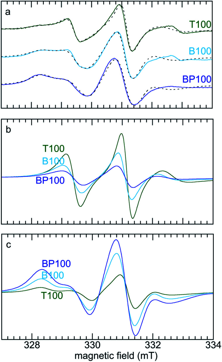
In order to quantify changes in the relative mobilities of tethered TEMPO radicals, the room temperature EPR spectra of T100, B100 and BP100 were deconvoluted. The two components represent faster- and slower-moving populations of the spin label, corresponding to radicals experiencing weaker and stronger interactions, respectively, with the PMO surface. Simulations were performed with the appropriate Azz value for each PMO (measured at low temperature) and a literature value of the g-tensor of the TEMPO radical52 (precise determination of the g-tensor would require lineshape analysis at higher field).53 The simulated EPR spectra and their deconvoluted components are shown in Fig. 5.
Fig. 5. (a) Comparison of experimental (solid lines) and simulated (dashed lines) EPR spectra for three PMOs functionalized with TEMPO, and deconvolution of each EPR spectrum into (b) faster, and (c) slower components. Simulations were performed using g = [2.0097, 2.0064, 2.0025],52 and measured Azz values (Table 2). Values for Axx and Ayy (0.7 and 0.8 mT, respectively) were obtained as global curvefit parameters. The fraction of each component and its correlation time were refined for each fit.
For the most polar material (T100), the correlation times (τD) for the faster- and slower-moving components are 2.6 and 7.1 ns, respectively, with fractional contributions of 61 and 39% (Table 2). For the least polar material (BP100), both correlation times are higher (3.5 and 8.6 ns), as is the fractional contribution of the slower component (86%). These changes are consistent with stronger interactions (and therefore lower mobility) with the less polar surface for a higher fraction of the tethered spin labels.
Effect of surface polarity on molecular partitioning at solid–liquid interfaces
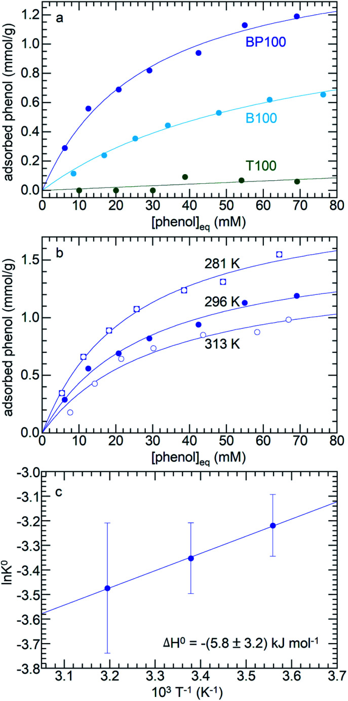
Three different molecules (phenol, p-cresol, furfural) considered representative of common types of functional groups present in lignocellulosic biomass were adsorbed on PMOs across the full range of surface polarities. Fig. 6a shows the adsorption isotherms for three PMOs (T100, B100, and BP100) in contact with aqueous phenol solutions (with initial phenol concentrations from 10 to 85 mM) at 296 K. Although phenol can interact with the surface hydroxyl groups of silica via hydrogen-bonding, its affinity for hydrated T100 is very low. Furthermore, even though all three silicas have similar surface hydroxyl densities (Table 1), the extent of phenol adsorption increases dramatically as the surface becomes less polar. Thus, phenol is much more strongly adsorbed onto B100 and BP100 (maximum values of ca. 0.7 and 1.3 mmol g–1, respectively).
Fig. 6. Equilibrium adsorption of phenol from water, onto: (a) T100, B100 and BP100, all at 296 K, and (b) BP100 at 281, 296, and 313 K. The isotherms (solid lines) represent non-linear curvefits using the Langmuir model (eqn (1)). (c) Van't Hoff plot for determination of adsorption enthalpy.
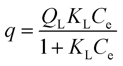
The adsorption isotherms for B100 and BP100 were analyzed with the Langmuir model, assuming monolayer sites. Eqn (1) relates the uptake of the adsorbate, q (in mmol g–1 adsorbent) to the equilibrium concentration in solution, Ce.
 |
1 |
QL is the maximum adsorption capacity. The Langmuir constant KL represents the affinity of the adsorption sites for the adsorbate. Non-linear curvefit parameters are shown in Table 3. The larger values of QL and KL for BP100, compared to B100, confirm that phenol has a higher affinity for the biphenylene-containing surface relative to the phenylene-containing surface. For neutral adsorbates, or adsorbates with small charges, KL is essentially equal to the thermodynamic equilibrium constant K°,54 whose temperature dependence is described by eqn (2).
| ln K° = ΔS°/R – ΔH°/RT | 2 |
Table 3. Langmuir analyses a of phenol adsorption from water onto PMOs.
| Material | T (K) | Q L (mmol g–1) | K L (L mmol–1) |
| B100 | 296 | 1.26 ± 0.11 | 0.015 ± 0.002 |
| BP100 | 313 | 1.45 ± 0.17 | 0.031 ± 0.008 |
| 296 | 1.66 ± 0.10 | 0.035 ± 0.005 | |
| 281 | 2.07 ± 0.10 | 0.040 ± 0.005 |
aBased on non-linear curvefits of the data presented in Fig. 6, using eqn (1).
The enthalpy of phenol adsorption, ΔH°, was obtained by extracting KL from adsorption isotherms recorded at different temperatures (Fig. 6b). According to the Van't Hoff plot in Fig. 6c, the value of ΔH° for phenol adsorption from water onto BP100 is –(5.8 ± 3.2) kJ mol–1, similar to a previously reported value for bentonite clay with intercalated hexadecyltrimethylammonium ions (–10.4 kJ mol–1).55 The values represent the small difference between the much larger enthalpies of phenol and water adsorption, and include the effect of phenol desolvation.56
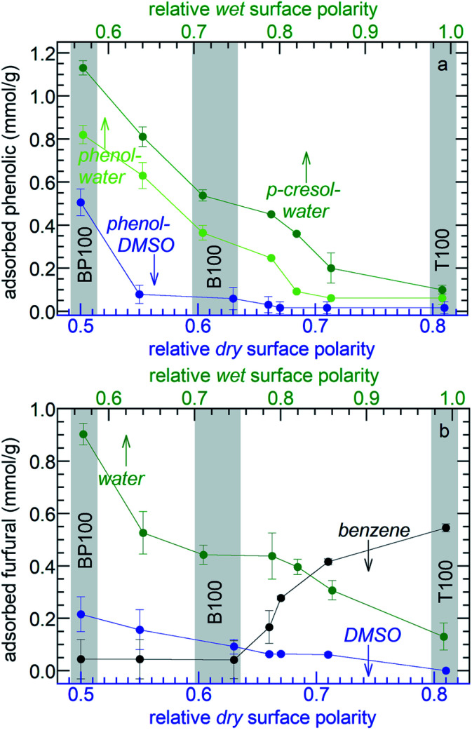
To investigate how systematically changing the surface polarity affects molecular adsorption, the phenol affinities of the entire PMO series were measured. Adsorption from aqueous solution is suppressed on more strongly hydrated polar surfaces (see above). Therefore aqueous solutions of phenol show monotonically decreasing adsorption as the polarity of the PMO increases (Fig. 7a and Table S5†). Formulated in terms of a Born–Haber cycle, the heat of adsorption represents the enthalpy costs to disrupt water–surface and water–phenol interactions, as well as the enthalpy gained in new water–water and phenol–surface interactions.56 Since the water–phenol and water–water contributions are the same for all PMO materials, the higher phenol affinities of the less polar PMOs must result from a combination of weaker water–surface interactions (manifested in the slope of Fig. 3c) as well as stronger phenol–surface interactions. Types of bonding characteristic of aromatic groups, such as H–π and π–π interactions, may contribute to the higher phenol affinities of the less polar PMOs.57
Fig. 7. Effect of PMO polarity on (a) amounts of phenol or p-cresol adsorbed from 40 mM solutions in water and DMSO; and (b) amounts of furfural adsorbed from 40 mM solutions in various solvents. In each experiment, 20 mg PMO was combined with 1.5 mL solution at 296 K.
The importance of solute-surface interactions is evident in the comparison of phenol (relative polarity 0.701) with the slightly less polar p-cresol (relative polarity 0.697).34 The effect of surface polarity on p-cresol affinity is even more pronounced (Fig. 7a). Thus B100 and BP100 adsorb 48 and 38% more p-cresol, respectively, than phenol. Since water–surface interactions are the same for both solutes, these differences are attributed stronger solute-surface interactions, in addition to weaker solvent–solute interactions.
Effect of solvent polarity on molecular partitioning at the solid–liquid interface
The choice of the solvent modulates the effect of surface polarity on molecular adsorption. For example, the phenol affinities of all the PMOs are dramatically lower when DMSO is the solvent instead of water, Fig. 7a. Thus phenol adsorption onto B100 from a DMSO solution decreased by 87%, compared to adsorption from an aqueous solution. Reasoning again in terms of Born–Haber cycles,56 we first note that phenol–surface interactions do not depend on solvent choice. The enthalpy cost to disrupt DMSO–phenol interactions is expected to be higher than for water–phenol interactions, since the dielectric constant of phenol (12)58 is closer to that of DMSO (46) than water (77, all at 30 °C).59 In addition, the enthalpy cost for disrupting interactions between the solvent and B100 is higher for DMSO than for water. Finally, solvent–solvent interactions are stronger for water than for DMSO. All three terms are expected to suppress adsorption of phenol from DMSO. Compared to B100, there is less suppression (38%) of phenol adsorption on BP100 upon changing the solvent from water to DMSO, presumably due to stronger phenol–surface interactions.
The effect of solvent polarity was further explored by comparing furfural adsorption from water, DMSO or benzene (with relative polarities of 1.00, 0.44, and 0.11, respectively). Similar to aqueous solutions of phenol and p-cresol, the affinities of the PMOs for furfural in water increase monotonically as the surface polarity decreases (Fig. 7b and Table S5†). The same trend is observed in less polar DMSO, although the absolute amounts of adsorbed furfural are much lower (for the same reasons described above for phenol adsorption from DMSO). Since the properties of furfural, as measured either by its dielectric constant (42)60 or by its relative polarity according to the solvatochromic dye method (0.43),60 are very close to that of DMSO, solvent and solute adsorption enthalpies are expected to be similar and solute–solvent interactions are presumably strong. The net result is a very weak effect of surface polarity on adsorption. However, the trend is reversed when furfural is dissolved in non-polar benzene. Now, the furfural affinities of the PMOs decrease with increasing surface polarity. Since benzene interacts weakly with furfural and with the more polar surfaces, furfural adsorption is favored. The three distinctly different trends in Fig. 7b illustrate the power of combining surface polarity modulation with appropriate choice of solvent to tune molecular adsorption.
Conclusions
This study sets the stage for design of porous solid catalysts with controlled surface polarity, in conjunction with rational solvent choice, to improve activity and selectivity in liquid-phase reactions by promoting preferential adsorption of reactants and desorption of desired products. The relative surface polarities of periodic mesoporous organosilicas (PMOs) can be tuned over a wide range by varying the chemical composition, independent of the textural properties. The mobility of near-surface molecules and their affinity for the surface are correlated with surface polarity. Tethered nitroxides experience decreased mobility as the surface polarity decreases, reflecting their increasingly strong association with the surface. Moreover, adsorption of organic molecules such as phenol, p-cresol, and furfural from polar solvents become more favorable as the surface polarity decreases. However, the effect can be reversed by changing the solvent polarity: thus such molecules adsorb less favorably from benzene as the surface polarity decreases. When the polarity of the solvent and solute are well-matched, adsorption is minimized. Thus, tuning the extent of adsorption precisely can be achieved by appropriate choices of solvent, surface polarity, and solute polarity.
This systematic study demonstrates how readily achieved variations in the surface polarity of PMO-based materials results in significant changes in adsorption equilibria for classes of molecules relevant to important catalytic reactions. While the consequences of surface and solvent polarity on adsorption are as expected, their rational prediction and ease of modulation suggests ways to design improved catalytic processes. Further refinements should include consideration of specific solute binding modes, such as cation–π interactions, electrostatic interactions, and H-bonding. Work is underway to include modification of PMO materials with active sites such as Brønsted/Lewis acid sites and metal nanoparticles, in order to assess polarity effects on heterogeneous reactivity.
Conflicts of interest
There are no conflicts to declare.
Supplementary Material
Acknowledgments
We are grateful to Jiafan Chen and Dr Jin-Ping Zhang (Suzhou Institute of Nano-Tech and Nano-Bionics) for some of the SEM images. We are grateful to Tarnuma Tabassum for her assistance with low temperature EPR measurements. We acknowledge funding from the U.S. National Science Foundation (NSF), Award No. CBET-1604095 (for materials synthesis and characterization) and CHE-1800596 (for surface spectroscopy). Some experiments made use of the MRL Shared Experimental Facilities, supported by the MRSEC Program of the NSF under Award No. DMR-1720256.
Footnotes
†Electronic supplementary information (ESI) available. See DOI: 10.1039/d0sc00168f
References
- Manayil J., Lee A., Wilson K. Molecules. 2019;24:239. doi: 10.3390/molecules24020239. [DOI] [PMC free article] [PubMed] [Google Scholar]
- Liu F., Huang K., Zheng A., Xiao F.-S., Dai S. ACS Catal. 2018;8:372–391. [Google Scholar]
- Sievers C., Noda Y., Qi L., Albuquerque E. M., Rioux R. M., Scott S. L. ACS Catal. 2016;6:8286–8307. [Google Scholar]
- Hu X., Wang S., Westerhof R. J. M., Wu L., Song Y., Dong D., Li C.-Z. Fuel. 2015;141:56–63. [Google Scholar]
- Mellmer M. A., Sener C., Gallo J. M. R., Luterbacher J. S., Alonso D. M., Dumesic J. A. Angew. Chem., Int. Ed. 2014;53:11872–11875. doi: 10.1002/anie.201408359. [DOI] [PubMed] [Google Scholar]
- Gilkey M. J., Xu B. ACS Catal. 2016;6:1420–1436. [Google Scholar]
- Wang C., Liu Z., Wang L., Dong X., Zhang J., Wang G., Han S., Meng X., Zheng A., Xiao F.-S. ACS Catal. 2018;8:474–481. [Google Scholar]
- Zapata P. A., Faria J., Ruiz M. P., Jentoft R. E., Resasco D. E. J. Am. Chem. Soc. 2012;134:8570–8578. doi: 10.1021/ja3015082. [DOI] [PubMed] [Google Scholar]
- Otomo R., Yokoi T., Tatsumi T. Appl. Catal., A. 2015;505:28–35. [Google Scholar]
- Li L., Yoshinaga Y., Okuhara T. Phys. Chem. Chem. Phys. 1999;1:4913–4918. [Google Scholar]
- Singappuli-Arachchige D., Kobayashi T., Wang Z., Burkhow S. J., Smith E. A., Pruski M., Slowing I. I. ACS Catal. 2019;9:5574–5582. [Google Scholar]
- Manayil J. C., dos Santos V. C., Jentoft F. C., Granollers Mesa M., Lee A. F., Wilson K. ChemCatChem. 2017;9:2231–2238. [Google Scholar]
- Singappuli-Arachchige D., Manzano J. S., Sherman L. M., Slowing I. I. ChemPhysChem. 2016;17:2982–2986. doi: 10.1002/cphc.201600740. [DOI] [PubMed] [Google Scholar]
- Karimi B., Mirzaei H. M. RSC Adv. 2013;3:20655–20661. [Google Scholar]
- Karimi B., Mirzaei H. M., Behzadnia H., Vali H. ACS Appl. Mater. Interfaces. 2015;7:19050–19059. doi: 10.1021/acsami.5b03985. [DOI] [PubMed] [Google Scholar]
- Pirez C., Lee A. F., Jones C., Wilson K. Catal. Today. 2014;234:167–173. [Google Scholar]
- Liu J., Yang J., Li C., Yang Q. J. Porous Mater. 2009;16:273–281. [Google Scholar]
- Yang Y., Sayari A. Chem. Mater. 2008;20:2980–2984. [Google Scholar]
- Kobayashi T., Pruski M. ACS Catal. 2019;9:7238–7249. [Google Scholar]
- Bradley R. H., Rand B. Carbon. 1993;31:269–272. [Google Scholar]
- Mietner J. B., Brieler F. J., Lee Y. J., Fröba M. Angew. Chem., Int. Ed. 2017;56:12348–12351. doi: 10.1002/anie.201705707. [DOI] [PubMed] [Google Scholar]
- Jahnke J. P., Idso M. N., Hussain S., Junk M. J. N., Fisher J. M., Phan D. D., Han S., Chmelka B. F. J. Am. Chem. Soc. 2018;140:3892–3906. doi: 10.1021/jacs.7b06863. [DOI] [PMC free article] [PubMed] [Google Scholar]
- Bordignon E., Brutlach H., Urban L., Hideg K., Savitsky A., Schnegg A., Gast P., Engelhard M., Groenen E. J. J., Möbius K., Steinhoff H.-J. Appl. Magn. Reson. 2010;37:391–403. [Google Scholar]
- Zhao D., Feng J., Huo Q., Melosh N., Fredrickson G. H., Chmelka B. F., Stucky G. D. Science. 1998;279:548–552. doi: 10.1126/science.279.5350.548. [DOI] [PubMed] [Google Scholar]
- Goto Y., Inagaki S. Chem. Commun. 2002:2410–2411. doi: 10.1039/b207825b. [DOI] [PubMed] [Google Scholar]
- Brinker C. J. J. Non-Cryst. Solids. 1988;100:31–50. [Google Scholar]
- Bao X. Y., Zhao X. S., Qiao S. Z., Bhatia S. K. J. Phys. Chem. B. 2004;108:16441–16450. [Google Scholar]
- Bao X. Y., Zhao X. S., Li X., Chia P. A., Li J. J. Phys. Chem. B. 2004;108:4684–4689. [Google Scholar]
- Kleitz F., Solovyov L. A., Anilkumar G. M., Choi S. H., Ryoo R. Chem. Commun. 2004:1536–1537. doi: 10.1039/b403903c. [DOI] [PubMed] [Google Scholar]
- Kim T.-W., Kleitz F., Paul B., Ryoo R. J. Am. Chem. Soc. 2005;127:7601–7610. doi: 10.1021/ja042601m. [DOI] [PubMed] [Google Scholar]
- Yang Y., Sayari A. Chem. Mater. 2007;19:4117–4119. [Google Scholar]
- Jelinek L., Kovats E. S. Z. Langmuir. 1994;10:4225–4231. [Google Scholar]
- Rice G. L., Scott S. L. Langmuir. 1997;13:1545–1551. [Google Scholar]
- Reichardt C. and Welton T., Solvents and Solvent Effects in Organic Chemistry, Wiley-VCH, Weinheim, 4th edn, 2011. [Google Scholar]
- Catalan J., Perez P., Laynez J., Blanco F. G. J. Fluoresc. 1991;1:215–223. doi: 10.1007/BF00865246. [DOI] [PubMed] [Google Scholar]
- Ortony J. H., Cheng C.-Y., Franck J. M., Kausik R., Pavlova A., Hunt J., Han S. New J. Phys. 2011;13:015006. [Google Scholar]
- Schrader A. M., Monroe J. I., Sheil R., Dobbs H. A., Keller T. J., Li Y., Jain S., Shell M. S., Israelachvili J. N., Han S. Proc. Natl. Acad. Sci. U. S. A. 2018;115:2890–2895. doi: 10.1073/pnas.1722263115. [DOI] [PMC free article] [PubMed] [Google Scholar]
- Etienne E., Le Breton N., Martinho M., Mileo E., Belle V. Magn. Reson. Chem. 2017;55:714–719. doi: 10.1002/mrc.4578. [DOI] [PubMed] [Google Scholar]
- Stoll S., Schweiger A. J. Magn. Reson. 2006;178:42–55. doi: 10.1016/j.jmr.2005.08.013. [DOI] [PubMed] [Google Scholar]
- Cubo A., Iglesias J., Morales G., Melero J. A., Moreno J., Sánchez-Vázquez R. Appl. Catal., A. 2017;531:151–160. [Google Scholar]
- Hammes K., Smernik R. J., Skjemstad J. O., Schmidt M. W. I. J. Appl. Geochem. 2008;23:2113–2122. [Google Scholar]
- Zhuravlev L. T. Colloids Surf., A. 2000;173:1–38. [Google Scholar]
- Ide M., El-Roz M., De Canck E., Vicente A., Planckaert T., Bogaerts T., Van Driessche I., Lynen F., Van Speybroeck V., Thybault-Starzyk F., Van Der Voort P. Phys. Chem. Chem. Phys. 2013;15:642–650. doi: 10.1039/c2cp42811c. [DOI] [PubMed] [Google Scholar]
- Gallas J. P., Goupil J. M., Vimont A., Lavalley J. C., Gil B., Gilson J. P., Miserque O. Langmuir. 2009;25:5825–5834. doi: 10.1021/la802688w. [DOI] [PubMed] [Google Scholar]
- Giovambattista N., Debenedetti P. G., Rossky P. J. J. Phys. Chem. B. 2007;111:9581–9587. doi: 10.1021/jp071957s. [DOI] [PubMed] [Google Scholar]
- Lin F., Meng X., Mertens M., Cool P., Van Doorslaer S. Phys. Chem. Chem. Phys. 2014;16:22623–22631. doi: 10.1039/c4cp03778b. [DOI] [PubMed] [Google Scholar]
- Pivtsov A., Wessig M., Klovak V., Polarz S., Drescher M. J. Phys. Chem. C. 2018;122:5376–5384. [Google Scholar]
- Wessig M., Drescher M., Polarz S. J. Phys. Chem. C. 2013;117:2805–2816. [Google Scholar]
- Mason R. P., Polnaszek C. F., Freed J. H. J. Phys. Chem. 1974;78:1324–1329. [Google Scholar]
- McBride M. B., in Advanced Chemical Methods for Soil and Clay Minerals Research, ed. J. W. Stucki and W. L. Banwart, NATO Sci. Ser. C: Springer, Dordrecht, 1980, vol. 63, pp. 423–450. [Google Scholar]
- de Biasi R. S., Fernandes A. A. R. J. Phys. C: Solid State Phys. 1983;16:5481–5489. [Google Scholar]
- Ottaviani M. F., Garcia-Garibay M., Turro N. J. Colloids Surf., A. 1993;72:321–332. [Google Scholar]
- Dzikovski B., Tipikin D., Livshits V., Earle K., Freed J. Phys. Chem. Chem. Phys. 2009;11:6676–6688. doi: 10.1039/b903490k. [DOI] [PMC free article] [PubMed] [Google Scholar]
- Liu Y. J. Chem. Eng. Data. 2009;54:1981–1985. [Google Scholar]
- Ocampo-Perez R., Leyva-Ramos R., Mendoza-Barron J., Guerrero-Coronado R. M. J. Colloid Interface Sci. 2011;364:195–204. doi: 10.1016/j.jcis.2011.08.032. [DOI] [PubMed] [Google Scholar]
- Singh N., Campbell C. T. ACS Catal. 2019;9:8116–8127. [Google Scholar]
- Keiluweit M., Kleber M. Environ. Sci. Technol. 2009;43:3421–3429. doi: 10.1021/es8033044. [DOI] [PubMed] [Google Scholar]
- Haynes W. M., Lide D. R. and Bruno T. J., CRC Handbook of Chemistry and Physics, CRC Press, 97th edn, 2017, pp. 6–217. [Google Scholar]
- Płowaś I., Swiergiel J., Jadżyn J. J. Chem. Eng. Data. 2013;58:1741–1746. [Google Scholar]
- Hoydonckx H. E., Van Rhijn W., De Vos D. E. and Jacobs P. A., in Ullmann’s Encyclopedia of Industrial Chemistry, 2007, vol. 16, pp. 285–313. [Google Scholar]
Associated Data
This section collects any data citations, data availability statements, or supplementary materials included in this article.


