Abstract
Quasi-fractal gold nanoparticles can be synthesized via a modified and temperature controlled procedure initially used for the synthesis of star-like gold nanoparticles. The surface features of nanoparticles lead to improved enhancement of Raman scattering intensity of analyte molecules due to the increased number of sharp surface features possessing numerous localized surface plasmon resonances (LSPR). The LSPR is affected by the size and shape of surface features as well as inter-nanoparticle interactions, as these affect the oscillation modes of electrons on the nanoparticle surfaces. The effect of the particle morphologies on the localized surface plasmon resonance (LSPR) and on the surface-enhancing capabilities of these nanoparticles is explored by comparing different nanoparticle morphologies and concentrations. We show that in a fixed nanoparticle concentration regime, quasi-fractal gold nanoparticles (gold nanocaltrop) provide the highest level of surface enhancement, whereas spherical nanoparticles provide the largest enhancement in a fixed gold concentration regime. The presence of highly branched features enables these nanoparticles to couple with a laser wavelength, despite having no strong absorption band and hence no single surface plasmon resonance. This cumulative LSPR may allow these nanoparticles to be used in a variety of applications in which laser wavelength flexibility is beneficial, such as in medical imaging applications where fluorescence at short laser wavelengths may be coupled with non-fluorescing long laser wavelengths for molecular sensing.
Keywords: Gold nanoparticles, surface-enhanced Raman scattering, localized surface plasmon resonances
1. Introduction
The magnitude of a Raman scattering signal can be improved by several orders of magnitude by having a roughened noble-metal substrate present or close to the sample being studied [1–3]. The enhancement provided by noble metal substrates can be mimicked by nanoparticles and described by their local surface curvature and size [4, 5]. The varied surface features present on some nanoparticle morphologies affects the adsorption of molecules on the nanoparticle as well as the oscillation modes of surface electrons, and hence the interaction of molecules with the local surface plasmons. Thus, a collection of nanoparticles with numerous sharp surface features should provide more surface-enhancement than a collection of similarly sized nanoparticles with smooth surfaces. Explanations of Raman surface-enhancement are based on several phenomena: collective nanoparticle surface plasmons, localized surface plasmons of individual nanoparticle features, and electromagnetic field line crowding (hotspots). The presence of hotspots can in part be due to the surface roughness of nanoparticles, as well as the nanoscale spaces present between nanoparticles [6–8]. Additionally, the local electromagnetic field associated with surface plasmon resonances (SPR) can be increased through the presence of high-curvature surface features, such as sharp tips or points. Nanoparticles with sharp surface features, such as star-like gold nanoparticles (SGN), have a demonstrated sensitivity to changes in the dielectric environment, in addition to a large surface-enhancing potential, as compared with more uniform nanoparticles of similar size [9–11].
The effect of nanoparticle concentration on their ability to provide surface enhancement has also been studied. The sometimes intuitive approach of increasing the number of nanoparticles to increase the signal intensity may prevent molecules from adsorbing on plasmonic nanoparticles because of nanoparticle aggregation, limiting the ability for the molecule’s signal to be enhanced. It has been shown that there are ideal concentrations of plasmonic nanoparticles for use in surface-enhanced Raman spectroscopy (SERS) based on nanoparticle surface geometry and surface plasmon resonance. Ideally, the ratio of nanoparticles to analyte should be kept low enough to establish a monolayer of nanoparticles on a surface, with enough analyte to not completely cover a nanoparticle’s surface [12, 13].
In the present work, we studied the effects of two properties of gold quasi-fractal nanoparticle systems on their Raman signal enhancement: (1) The effect of nanoparticle morphology on their surface-enhancing potential and the relationship between the surface plasmon resonance (SPR) and the morphology and size, and (2) The effect of nanoparticle concentration on a system that possesses varying surface plasmon resonances and differing levels of surface inhomogeneity. These effects were tested using malachite green dye on nanoparticle coated silicon surfaces to allow for identical sample preparation and sample interaction volumes.
2. Materials and Methods
2.1. Nanoparticle syntheses
All chemicals utilized for the nanoparticle syntheses were purchased from Sigma-Aldrich. Ultrapure de-ionized water (18.2 MΩ-cm) was obtained from a Millipore Direct Q3 water system. The star-like and gold nanocaltrop (quasi-fractal) syntheses were performed in a three-neck flask fitted with a Graham type condenser (400 mm) to establish a reflux system. The flask was filled with 10 mL of room temperature deionized water under constant magnetic stirring (500 rpm) and placed in a water bath and allowed to equilibrate. Then, 9 μL of a 0.013 mM solution of HAuCl4 (Sigma-Aldrich Cat. #484385) was added to the flask. After a few minutes of mixing, 100 μL of 11 mg/mL hydroquinone solution (Sigma-Aldrich Cat. #H9003) was added into the flask and mixed for 5 minutes. The synthesis was concluded with the addition of 20 μL of 10 mg/mL sodium citrate tribasic dihydrate (Sigma-Aldrich Cat. #S4641) solution to function as a capping agent for the particles and to increase their stability [9]. The flasks for the syntheses at temperatures of 45ºC and higher were then held in an 8ºC water bath for 15 minutes to quench additional reaction, and then allowed to reach room temperature for UV/Vis measurements.
The spherical gold nanoparticle synthesis follows the method described by Schulz et al., wherein a 15 mL sodium citrate/citric acid buffer solution (Sigma-Aldrich Cat. #S4641 and # 251275) (molar ratio 75:25) is brought to reflux and then mixed with 150 μL of 71.5 mM HAuCl4 solution. Formation of nanoparticles is confirmed by the mixture changing color from dark blue to dark red [14].
2.2. Characterization Techniques
UV/Visible Spectroscopy:
The UV/Visible absorption profiles of the nanoparticle suspensions were acquired with a ThermoFisher Scientific Evolution 220 Ultraviolet-Visible Spectrometer (UV/Vis) over the range of 190-1100 nm at room temperature. Nanoparticle suspensions were stirred vigorously before 1 mL aliquots were deposited into a quartz cuvette.
Electron Microscopy:
Electron microscopy was performed at Brookhaven National Laboratory’s Center for Functional Nanomaterials. Transmission electron microscopy (TEM) was performed on a JEOL JEM-1400 electron microscope at 120.0 kV and scanning electron microscopy (SEM) was performed on a JEOL JSM-7600F field emission SEM at 5.0 kV. To prepare samples, 5 μL of nanoparticle suspensions were deposited on a copper grid (Ted Pella, Formvar/carbon 400 mesh) and allowed to dry. The grids were used for both transmission and scanning electron microscopy. TEM images were used to calculate the isoperimetric ratios of the various nanoparticles using ImageJ software (see Supplemental Material, Figure S1).
Dynamic Light Scattering:
Dynamic light scattering measurements of the nanoparticle hydrodynamic diameters were also carried out at Brookhaven National Laboratory’s Center for Functional Nanomaterials on a Malvern Zetasizer Nano-ZS at 25.0ºC with the refractive index set to 1.400 and the absorption set to 0.100. Three cycles were run to measure the intensity average from which sizes were determined. This was done for three different syntheses to provide an overall data set.
SERS - Sample Preparation:
Samples for surface-enhanced Raman Spectroscopy experiments were produced using pre-cut silicon wafers [p-type (boron)] (Ted Pella, 5×5mm diced). Silicon sections were washed for several minutes in a 1:100 (v/v) solution of 37% HCl with 70% ethanol (both from Fisher Scientific). After rinsing with copious amounts of deionized water and allowed to dry, the clean and dry silicon sections were placed in a 0.01 % (w/v) poly-L-lysine solution (Sigma Aldrich) for 5 minutes. The poly-L-lysine functionalized silicon sections were dried at 60ºC for 1 hour and then removed and cooled to room temperature, followed by 24 hours of incubation in nanoparticle suspensions at room temperature. After being removed and allowed to dry, 15 μL aliquots of 1.12 μM malachite green dye (Sigma-Aldrich Cat.#M6880) solution were then drop cast onto the samples and allowed to dry.
Two sets of samples were prepared: (1) A-set utilized nanoparticles as-prepared with identical initial concentrations of gold precursor, resulting in varied nanoparticle concentrations, and (2) B-set was prepared by diluting the original nanoparticle solutions with deionized water, such that all samples had identical concentrations of nanoparticles, resulting in different total amounts of gold. Theoretical concentrations of nanoparticles (3.8x10⁸ np/mL) were calculated based on total amount of gold and nanoparticle hydrodynamic diameters.
SERS – Raman Setup/Processing:
Raman measurements were performed on a HORIBA XploRA PLUS Raman microscope equipped with a motorized stage. Collection settings were a 638 nm laser (25mW) at 1% laser power, 100X objective, 600 gr/mm grating, 100 μm hole, 50 μm slit, with a 0.5 second acquisition time with 1 acquisition per step. Each sample was mapped three times in random locations, with maps measuring 16x16 μm2 with a step size of 0.2 μm in all directions. The data was truncated to the [150-2000] cm−1 range, and then a background was removed from all of the samples (9th degree polynomial with 256 data points) to account for any heating or fluorescent effects. A square cursor with an area of 5 μm2 was centered on the location where the maximum intensity Raman signal was measured, and all of the spectra contained were averaged. This was repeated for each of the sample’s three maps and then averaged together. In this way, the average Raman enhancement provided by each sample could be demonstrated.
The area for averaging signals was chosen based on previous studies that established that a square area with sides of 5 μm would provide consistent average spectra, despite varied levels of sample aggregation [9]. The signal to noise ratio (SNR) has been employed to measure the quality of the Raman spectra obtained by calculating the weighted value of the heights of spectral peaks of interest to the height of the background noise. As the background noise becomes larger, the SNR decreases, demonstrating the loss of signal quality. The SNR is calculated from the following expression:
where S is the height of the analyte peak above the background and B is the average height of the background peak. The background peak is measured in a region where no Raman signal is present [15]. This is a simplified expression because it does not include dark signal and readout noise because a CCD detector was used.
For quantitative comparisons between the surface-enhancing potential of each nanoparticle candidate, the analytical enhancement factor (AEF) is employed. The AEF is defined by the expression:
where and IRS are the spectral peak heights of malachite green, with and without nanoparticles, respectively, and and are the concentrations of malachite green in samples, with and without nanoparticles, respectively. Since the AEF depends on concentration, it will be strongly affected by the presence of mono- or multi-layers of the analyte molecule in the sample and by the method of analyte deposition. However, if sample preparation is performed identically and dye concentration is limited to provide for sub-monolayer coverage, then the AEF allows for quantitative comparisons across all the samples [16].
3. Results and Discussion
3.1. Nanoparticle surface morphology and sizes
The level of surface inhomogeneity and branching was controlled by modifying the star-like nanoparticle (SGN) synthesis temperature. Nanoparticles with original star-like morphology were synthesized at 25ºC, whereas nanoparticles with branched quasi-fractal morphology, referred to herein as gold nanocaltrops (GNC), could be synthesized at temperatures ≥ 45ºC, with an upper limit not yet established [1]. The particle suspensions exhibited magenta/lavender color at synthesis temperatures < 25ºC, blue color at synthesis temperatures of 25ºC and 35ºC, and were light blue to transparent at temperatures of 45ºC and higher, as shown in Figure 1(a). The color intensity of the suspensions was inversely correlated with the reaction temperature, indicating a decreasing nanoparticle concentration. The synthesis consisted of the reduction of HAuCl4 by hydroquinone at different reaction temperatures, followed by stabilization of the resultiñg nanoparticles with sodium citrate, as shown schematically in Figure 1(b). At temperatures of 25ºC and 35ºC, the synthesis outcome consists of SGN, while at temperatures of 45ºC and higher the synthesis outcome consists of GNC. From a mechanistic point of view, it was important to probe whether uncapped SGN formed at low temperatures could be transformed into GNC upon increasing the suspension temperature to T ≥ 45ºC. If the GNC were formed by the aggregation and crystal rearrangement of the uncapped SGN, then the SGN constitute intermediates in the formation of the GNC. In initial experiments, we first synthesized SGN at 25ºC, followed by the heating the unstabilized (uncapped) suspensions to 65ºC in the same reaction medium. The outcome of the experiments showed that heated, uncapped SGN did not transform into GNC, as shown schematically in Figure 1(b). Moreover, the heated uncapped SGN exhibited a blue-shifted UV-Vis absorption profile, as shown in Figure 1(c). The suppression of the uncapped SGN longitudinal mode at 615 nm is accompanied by an increase and slight blue-shift in the transverse mode, which moved from 545 nm to 534 nm. This may be indicative of a thermally-induced crystal annealing [17–19], leading to smoother, and sphere-like SGN. These results suggest that each synthesis temperature provides for unique kinematics, and that the formation of SGN during the growth of GNC is unlikely.
Figure 1.
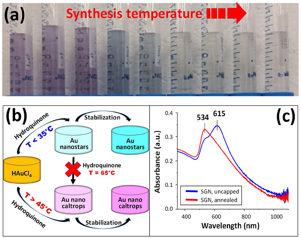
Synthesis scheme and resulting nanoparticle suspension characteristics. (a) Varying shades of magenta, blue, light blue and transparent gold nanoparticle suspensions.Nanoparticle suspensions shown contain the same concentration of gold precursor and varying concentrations of nanoparticles. Sample synthesis temperatures from left to right: 0.5ºC, 3.8ºC, 13.8ºC, 25ºC, 35ºC, 45ºC, 55ºC, 65ºC, and 75ºC. (b) Schematics of the synthesis.The reaction gives rise to star-like nanoparticles in the low temperature regime and to quasi-fractal nanoparticles in the high temperature regime. Note that the heating of unstabilized nanoparticles formed in the low temperature regime does not give rise to morphologies expected in the high temperature regime. (c) Heating of the unstabilized nanoparticles formed in the low temperature regime gives rise to a blue-shifted UV-Vis spectrum, indicating a thermally-induced crystal annealing, leading to a more sphere-like morphology.
The growth dynamics of branched particles with high surface complexity has been shown to be the result of a kinetically-driven growth process, with hydroquinone in particular allowing for the growth of branched structures. Similar to previous observations [9, 10, 20–28], the growth process is driven by the low reduction potential of hydroquinone leading to the combined effects of the modulation of the kinetics of AuIII → AuI → Au0 stepwise reduction, and the preferential deposition of Au0 onto the more reactive planes of the growing gold nanocrystals [20–27].
At low temperatures (and in the absence of seeds), the reaction is dominated by the presence of the AuI intermediates, with a slow transformation into the fully reduced Au0 fragments, which in turn act as seeds for the nanoparticle growth. At higher temperatures, the kinetics of the stepwise reduction reaction increase and generate a sudden high concentration of Au0 fragments, self-catalyzing a faster and more random deposition of Au0 [28]. Moreover, it has been shown that higher temperatures also increase the reactivity of high-order crystaI facets such as the (1 1 1), (2 0 0), (2 2 0), (3 1 1) and (4 1 1) planes [29–31], thus promoting the development of growth anisotropy, resulting in nanoparticles with various morphological surface features. As expected, the X-ray diffraction patters of synthesized gold nanospheres and of samples synthesized at 25ºC and 65ºC exhibited the diffraction peaks from the (1 1 1), (2 0 0), (2 2 0) and (3 1 1) crystal planes [29–31], albeit with slightly different ratios that were not analytically significant (see Supplemental Material Figure S2).
At synthesis temperatures above 35ºC, it is possible that the particles undergo some degree of Ostwald ripening, such that they tend to become larger at the expense of smaller particles that are dissolving [32, 33]. Under these circumstances, there may be a competition between the faster AuI → Au0 reduction by hydroquinone followed by the rapid deposition of Au0, and Ostwald ripening. However, the occurrence and the extent of the Ostwald ripening process on the systems studied here may not be properly assessed, since no time-dependent experiments have been performed. Previous synthesis techniques utilizing the reduction of HAuCl4 demonstrated that at lower synthesis temperatures, Ostwald ripening could be delayed and the distribution of nanoparticle size features could be narrowed [34].
The unique fractal morphology of the GNC occurs at a synthesis temperature of 45ºC and above, with fractal characteristics increasing with temperature, as shown in TEM images in Figure 2 and SEM images in Figure 3. Nanoparticles synthesized at temperatures < 25ºC exhibited a mixed set of multi-faceted, spherical, and oblate morphologies, shown in Figure 2 (a–c), those synthesized at 25ºC exhibited a consistent star-like morphology, shown in Figure 2 (d), while nanoparticles synthesized by the same procedure at temperature ≥ 45ºC exhibited a quasi-fractal shape, shown in Figure 2 (f,g,h,i). The DLS characterization of the nanoparticle hydrodynamic diameters demonstrates an overall increase in size with increasing synthesis temperature, as shown in Figure 4a. Moreover, as may be observed from the TEM and SEM images, the nanoparticle fractal characteristics increase with the increasing synthesis temperature. The extent of fractal features may be evaluated by computing the isoperimetric ratios of the non-overlapping nanoparticles for each temperature. The variations of the measured isoperimetric ratios can be used to demonstrate how much a particular shape deviates from a circle (P = L2/A = 4π2r2/πr2 = 4π = 12.6) and hence, indicate the degree of surface inhomogeneity and fractal character for a particular set of geometries [1]. The isoperimetric ratios for all synthesized nanoparticles are shown in Figure 4b. Similar to the trends observed in the DLS size measurements, nanoparticles synthesized at temperatures ≤ 25ºC possess similar diameters and a similar degree of fractal character, while particles synthesized at 35ºC and higher possess increasing sizes and fractal characteristics. These results suggest that the reaction kinetics may be defined by two different temperature regimes: (1) T ≤ 35ºC and (2) T ≥ 45ºC, consistent with the two regimes observed for the particle size distributions.
Figure 2.
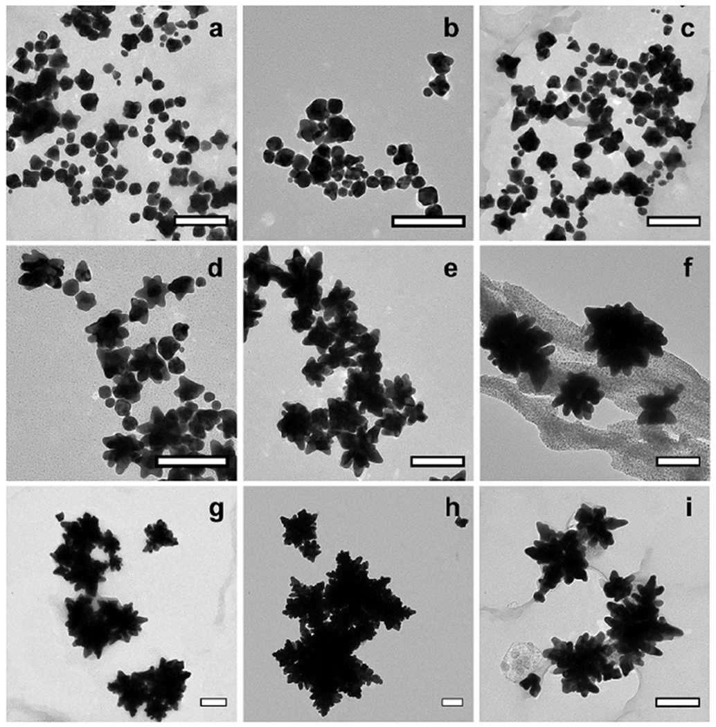
TEM images of nanoparticles synthesized at various temperatures. (a) 0.5ºC, (b) 3.8ºC, (c) 13.8ºC, (d) 25ºC, (e) 35ºC, (f) 45ºC, (g) 55ºC, (h) 65ºC, and (i) 75ºC. Scale bars = 150 nm.
Figure 3.
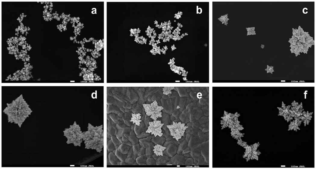
SEM images of synthesized nanoparticles. (a) 25ºC, (b) 35ºC, (c) 45ºC, (d) 55, (e) 65, and (f) 75ºC. Scale bars = 100 nm.
Figure 4:
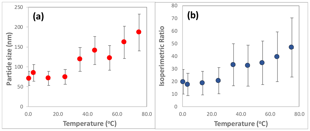
Characteristics of the synthesized gold nanoparticles. (a) Nanoparticle diameters as measured by DLS. (b) The isoperimetric ratios as measured by ImageJ (see Figure S1 in the supplemental material section), and verified by our own Matlab software [1].
3.2. Surface plasmon resonances
The UV/Visible spectra reveal a reduction in surface plasmon resonance intensity and peak broadening, as well as an increasing red-shift in samples synthesized at increasing temperatures, as shown in Figure 5(a). A distinct change in SPR shape and position is observed in nanoparticles synthesized at 35–75ºC, as compared to nanoparticles synthesized at 0–25ºC, indicating a change in the overall nanoparticle morphology from star-like to nanocaltrop. Less pronounced differences in SPR peak shape and position can be also noted between spherical particles synthesized at 0–5ºC and star-like nanoparticles synthesized at 15–25ºC. Precisely, the absorption profile of star-like gold nanoparticles possesses two major peaks in the 500–800 nm region, whereas spherical nanoparticles have a single peak in the 520–575 nm range. The 535 nm peak of star-like nanoparticles is similar to the transverse oscillation mode observed on other gold nanoparticles, such as gold nanorods and nanoparticle dimer assemblies [35, 36], and the second peak at 620 nm is the result of the branch features present on the samples. A similar trend was observed by Bakr et al. [37], who reported that gold nanoparticles with multiple branches resembling the shape of sea urchins demonstrated a shift in the SPR from 585 to 622 nm together with peak broadening due to particle branching. Previous work by Morasso et al. shows similar UV/Vis structures, demonstrating the reproducibility of the morphology synthesized at 25ºC [9].
Figure 5:
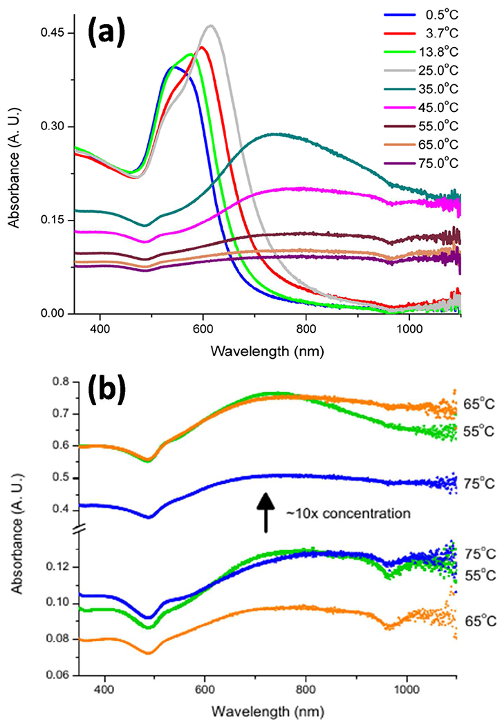
(a) UV/Visible spectra for the as-synthesized nanoparticle suspensions. (b) UV/Visible spectra for gold nanocaltrop samples before and after a ten-fold suspension concentrating. Concentrated samples show no change in absorption profile other than in increase in absorbance. Note the break and change of scale in the absorbance axis.
The decrease of the 620 nm peak intensity and the broadening of the spectra with increased synthesis temperature are believed to result from a contribution of numerous smaller surface features of varying sizes, likely causing multiple absorption peaks and yielding the broad unresolved absorption band. The superposition of all possible absorption bands from the surface features suppress the existence of a single absorption maximum [38–40]. To confirm that the absence of a distinct surface plasmon resonance peak for the GNCs synthesized at ≥ 55ºC is not a concentration effect, the UV/Vis absorption spectra of ten-fold concentrated (via rotary evaporation) suspensions was measured, and shown in Figure 5(b). While the intensity of the absorption spectra increased in concentrated samples, the overall spectral profile remained the same, indicating that the absence of a distinct SPR for the GNC morphologies is independent of sample concentration. This confirms that the broadening of absorption profiles in the studied samples is related to the presence of multiple, non-uniform nanoscale surface features [41].
3.3. Enhancement of Raman scattering
The surface plasmon of the nanoparticle suspensions is typically a strong indicator of their ability to provide surface-enhancement, as the electric field generated via the oscillating surface plasmons is thought to couple with incident photons, providing the signal enhancement characteristic of SERS [5]. Collection of the Raman spectra of malachite green enhanced by the presence of Au nanoparticles are shown in Figure 6.
Figure 6:
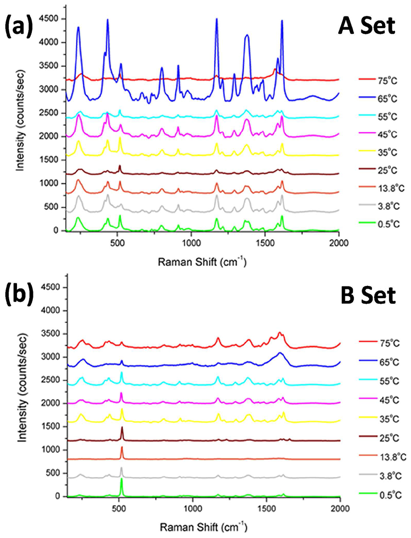
SERS of malachite green on Au nanoparticle substrates. (a) A-set nanoparticle substrates from suspensions with a constant Au atom concentration, (b) B-set nanoparticle substrates from suspensions with constant nanoparticle concentration. Spectra have been shifted by 400 counts/sec each for clarity.
In order to allow for quantitative comparisons of the Raman spectra, sample preparation and Raman measurements were performed under identical conditions. Furthermore, an optical plane (plane of focus that determines the laser interaction volume in the sample) was established across all samples, regardless of material height, to avoid any ambiguity in collecting spectra and altering the signal intensity. The laser was focused on an area devoid of optical sample and then the sample height was varied so as to maximize the 520 cm−1 Si spectral line. The sample height was then locked, and scans were performed in total darkness.
In order to properly assess the main parameters affecting the extent of spectral enhancement of malachite green by the gold nanoparticles, two types of gold suspensions were examined over the broad range of temperatures: (1) Suspension having a fixed concentration of gold atoms, i.e. identical initial concentrations of HAuCl4 precursor (A-set), and (2) Suspensions having identical concentrations of gold nanoparticles (B-set). The A-set represents Raman spectra of malachite green that was deposited on Au nanoparticle substrates that were generated from suspensions with the same concentration of gold atoms, and are shown in Figure 6a. The intensity of the malachite green peaks observed in the various samples indicates an overall increase as a function of synthesis temperature of the nanoparticles but does not provide a conclusive correlation between enhancement and particle morphology. This could be due to the fact that at the higher temperatures, larger and more inhomogeneous nanoparticles are formed, leading to nanoparticle concentrations up to two orders of magnitude lower than at lower temperatures. The concentrations of the original nanoparticle suspensions, their average diameters as measured by DLS, and the required dilution factors required to generate suspensions of equal nanoparticle concentrations are summarized Table 1.
Table 1:
Undiluted nanoparticle concentrations, measured DLS diameters, and dilution factor for B-set samples with a final concentration of 3.8x10⁸ np/mL.
| Synthesis temperature [ºC] and nanoparticle morphology | Concentration of original suspensions [x108 np/mL] | DLS diameter [nm] | Dilution factor |
|---|---|---|---|
| Spheres | 135.8 | 58.7 | 35.55 |
| 0.5ºC | 69.4 | 70.9 | 18.17 |
| 3.8ºC | 41.0 | 84.5 | 10.73 |
| 13.8ºC | 69.6 | 71.2 | 17.97 |
| 25.0ºC / SGN | 60.2 | 74.4 | 15.76 |
| 35.0ºC | 14.8 | 118.7 | 3.87 |
| 45.0ºC / GNC | 8.8 | 141.4 | 2.29 |
| 55.0ºC / GNC | 13.5 | 122.4 | 3.53 |
| 65.0ºC / GNC | 5.8 | 161.8 | 1.53 |
| 75.0ºC / GNC | 3.8 | 186.4 | 1.00 |
The B-set represents Raman spectra of malachite green that was deposited on Au nanoparticle substrates that were generated from suspensions with the same concentration of gold nanoparticles, and are shown in Figure 6b. The intensity of the malachite green peaks observed in the various samples included in the B-set indicates an overall correlation with synthesis temperature as well as nanoparticle morphology. There is a direct correlation between the amount of adsorbed nanoparticles on the Si substrates and their concentration in the parent suspensions [42–45]. The transfer of the Au nanoparticles from their original aqueous suspension (either the A-set or the B-set) is driven by the net change in the Gibbs free energy, which in turn is a function of the equilibrium partition of the Au nanoparticles between the aqueous suspension and the Si surface, according to the following expression:
where is the equilibrium partition coefficient of the Au nanoparticles between the aqueous suspension and the immersed Si substrate, which is defined by the ratio between the concentration of the Au nanoparticles in the aqueous suspension and that on the Si surface, as shown below:
Unfortunately, nanoparticle suspensions are inherently two-phase systems, and even though they can be kinetically stable for long periods, they are far from thermodynamic equilibrium and cannot be equilibrated when exposed to a new phase, such as the Si substrate [46]. Despite the driving force for adsorption due to the electrostatic interaction between the poly-L-lysine coating on the Si surface and the negatively charged Au nanoparticles [45, 47], the translation of concentrations from 3D suspensions to 2D substrates may result in surface concentration errors as high as two orders of magnitude [44, 46, 48, 49]. Hence, the differences between the effects seen with the two types of samples should be viewed in this context.
The three main and most intense characteristic Raman peaks of malachite green chosen for analysis are observed at 1619 cm−1, 1371 cm−1 and 1176 cm−1, corresponding to symmetric ring breathing and C-C stretching of the aromatic rings, the phenyl-N stretch and the symmetric in-plane and out-of-plane bending of the rings, respectively [1, 50]. The A-set samples, characterized by a fixed concentration of gold atoms per sample, has an increasing average particle diameter and an overall decreasing concentration of nanoparticles as a function of increasing synthesis temperature. Conversely, a smaller surface density of nanoparticles in a sample implies a lower probability for interactions between incident photons and the corresponding surface plasmons, fact that would lead to fewer sites involved in surface enhancement. On the other hand, the larger nanoparticles possess a higher degree of surface inhomogeneities, which in turn could generated a higher concentration of high curvature sites that increase surface enhancement. Therefore, while there is an overall enhancement effect observed with the A-set samples, it does not apply consistently to all temperatures. The B-set, by contrast, characterized by a fixed concentration of nanoparticles, clearly demonstrates an increase in the GNC surface-enhancing capability with increasing temperature of nanoparticle synthesis. It is interesting to note that the increased enhancement is generated by particles with red-shifted plasmons, which implies that the main source of the surface enhancement from these samples is not strictly surface plasmon dependent. The surface-enhancing capabilities of these nanoparticles is more closely linked with the localized surface plasmon resonance, which varies on a particle-to-particle basis. The localized surface plasmon produces regions of highly concentrated electric fields, referred to as hot spots, which are affected by the degree of surface branching, and variations in local surface curvature [51,52].
The effect of the localized surface plasmon resonance contribution is highlighted by the low-concentration of the 65.0ºC/GNC sample in the A-set, which provided large relative surface enhancement across three separate maps, compared to the other samples. The conclusion is that despite the larger nanoparticles having a surface plasmon resonance wavelength greater than 780 nm (see Figure 5), which is greater than the excitation laser wavelength of 638 nm, the more fractal gold nanocaltrops provide better enhancement. In particular, morphologies that possess a high density of regions where curvature and branching are increased can provide numerous loci where molecules can interact with the localized-surface plasmon hot-spots, greatly enhancing their Raman spectra. This finding reinforces the idea that the ideal nanoparticle candidate for SERS does not necessarily need to have a surface plasmon resonance with the same wavelength as the excitation laser, as long as there exists local surface plasmons that are resonant with the laser wavelength and whose anisotropic features allow for strong electromagnetic field line crowding [53].
The increasing fractal nature of the star-like and nanocaltrop samples has also been compared with spherical gold nanoparticles, as shown in Figure 7. As previously reported, the enhancement provided by the spherical nanoparticles should be smaller than that provided by the star-like gold nanoparticles. The reported samples use fixed volumes of nanoparticle dispersions, but do not account for nanoparticle concentration [9]. The established nature of nanoparticle concentration and their effect on localized surface plasmons is exemplified in the A-set of spherical gold nanoparticles. The spherical nanoparticle dilution contained 1.35x10¹⁰ nanoparticles/mL compared to 6.02x10⁹ nanoparticles/mL for the 25.0ºC/SGN sample and 5.84x10⁸ nanoparticles/mL for the 65.0ºC/GNC samples. As may be noted in Figure 4a, the signal enhancement from the spherical nanoparticles is greater than those of the 25.0ºC/SGN and 65.0ºC/GNC samples, most likely due to the higher concentration of enhancers. Conversely, when nanoparticle concentrations are fixed in the parent suspensions, as shown in Figure 6b, the quasi-fractal nanoparticles exhibit the largest enhancement, as expected.
Figure 7:
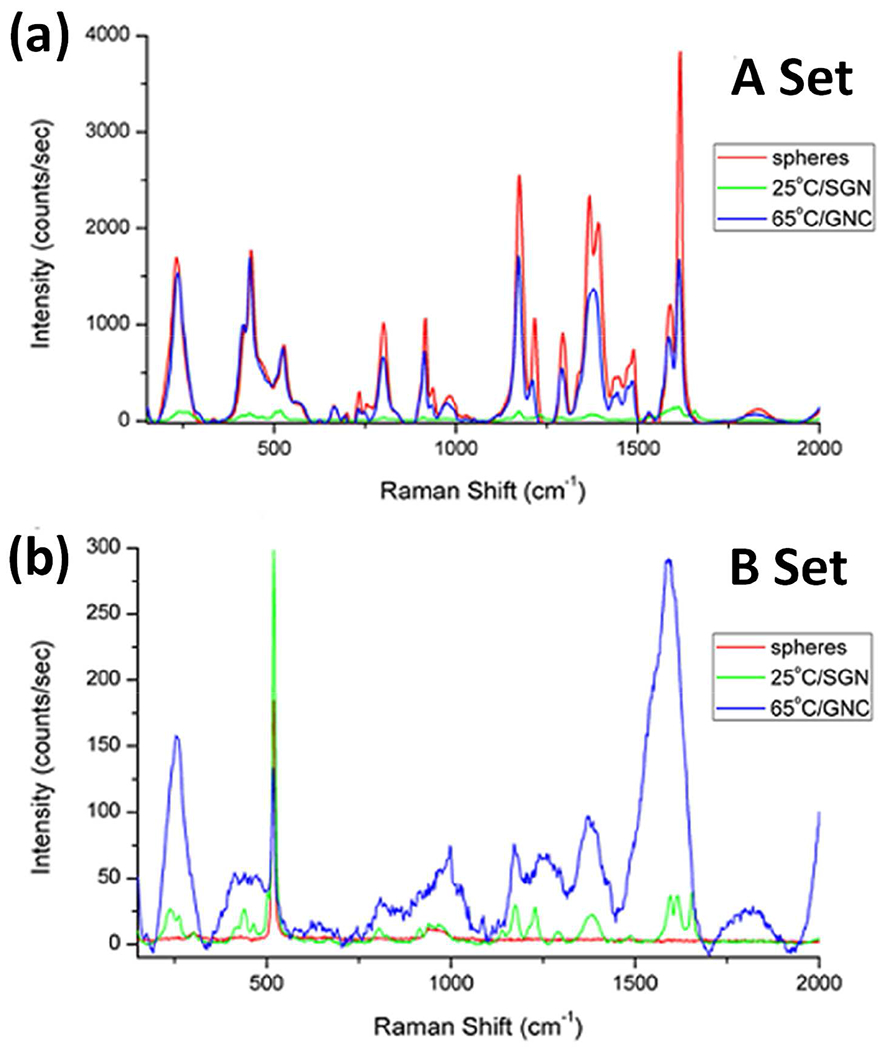
SERS Raman spectra of malachite green in the presence of spherical, star-like (at 25ºC), and quasi-crystal (at 65ºC) Au nanoparticle morphologies. (a) A-set (fixed concentration of gold atoms), and (b) B-set (fixed nanoparticle concentration).
The spherical nanoparticle plasmon (520 nm) is farther upfield from the excitation laser wavelength (638 nm) than the 25.0ºC star-like nanoparticle plasmon (625 nm). The spherical nanoparticle A-set sample possesses an order of magnitude more particles than the star-like and two orders of magnitude more particles than the nanocaltrop. Conversely, the spherical nanoparticle A-set sample possesses two orders of magnitude more AEF than the star-like but only one order of magnitude more than the nanocaltrop. This increased concentration allows for two conditions: (1) more localized plasmon modes due to the increased chance for grouped nanoparticle clusters, whose effects would resemble the high concentration of surface features present on the larger nanocaltrop, and (2) more regions with surface plasmon oscillations to couple with the laser wavelength, providing more surface-enhancing potential.
The various enhancement scenarios explored in this paper may be quantitatively assessed by calculating the AEF for each sample. The results are summarized in Table 2.
Table 2.
Calculation of the AEF values based on the I1619 malachite green peak for all nanoparticles in the A-set samples and The B-set samples.
| Synthesis Temperature and Nanoparticle Morphology | Equal Concentration of Au Atoms | Equal Concentration of Au Nanoparticles | ||
|---|---|---|---|---|
| I1619 [counts/s] | AEF (x104) | I1619 [counts/s] | AEF (x104) | |
| Spheres | 3828.6 | 209.4 | 2.7 | 0.1 |
| 0.5ºC | 322.4 | 17.6 | 53.3 | 2.9 |
| 3.8ºC | 357.3 | 19.5 | 66.6 | 3.6 |
| 113.8ºC | 259.1 | 14.0 | 19.3 | 1.1 |
| 25.0ºC / SGN | 142.5 | 7.8 | 36.6 | 7.8 |
| 35.0ºC | 249.0 | 13.6 | 216.5 | 11.8 |
| 45.0ºC / GNC | 431.6 | 23.6 | 103.3 | 5.6 |
| 55.0ºC / GNC | 158.1 | 8.6 | 114.6 | 6.3 |
| 65.0ºC / GNC | 1672.1 | 91.4 | 230.8 | 12.6 |
| 75.0ºC / GNC | 154.8 | 8.5 | 253.9 | 13.9 |
Calculation of the AEF values required an evaluation of the malachite green concentration on the sample substrates, both with and without the presence of nanoparticles. The molecule was assumed a sphere and its van der Waals volume was approximated by Chem2D as 8.23 Å. Its projection on the substrate would then be a circle of the same diameter. However, if a space-filling model is employed, then the area of the malachite green molecule may be approximated by a square with sides 8.23 Å, resulting in an area of 67.73 Å2. Using the total sample area of 25 mm2, we find that only 8.41·1011 malachite green molecules were present on the surface, which is about two orders of magnitude less than the 3.7 x10¹³ molecules required for complete monolayer coverage, Hence, it can be approximated that , and the expression for the calculation of AEF reduces to .
As may be noted from Table 2, the AEF for the samples containing Au spheres in the A set group outperformed the other morphologies, whereas in the B-set group, the AEF of the samples containing 75.0ºC/GNC exhibited the largest level of enhancement. For non-spherical Au nanoparticles, the degree of surface branching and variations in local surface curvature directly impact the presence of hot spots, which in turn are responsible for the surfaceenhancing capabilities of these nanoparticles. However, the expression for the calculation of AEF used to calculate the values in Table 2 does not include a term that would provide a quantitative dependence on surface morphology. To do so, we scaled the calculated AEF values by the term P/4π, which is the normalized isoperimetric ratio (where P/4π for a sphere is 1), and plotted the results side by side with the original AEF values, as shown in Figure 8. When comparing the enhancement efficiency for the samples with a constant initial gold concentration (Figure 8a), we find that when the geometry of the particles is taken into consideration, the samples containing the 65.0ºC/GNC particles exhibited the largest level of enhancement (Figure 8b). Similar results are also obtained for the enhancement of the other two main absorption bands of malachite green, i.e. 1371 cm−1 and 1176 cm−1. It is interesting to note that the degree of enhancement for these additional bands is not identical to that of the 1619 cm−1 band. This could be attributed to the fact that both the 1371 cm−1 and 1176 cm−1 bands represent directional bonds and hence are susceptible to the position of the molecule with respect to the hot spot electrical field vector.
Figure 8:
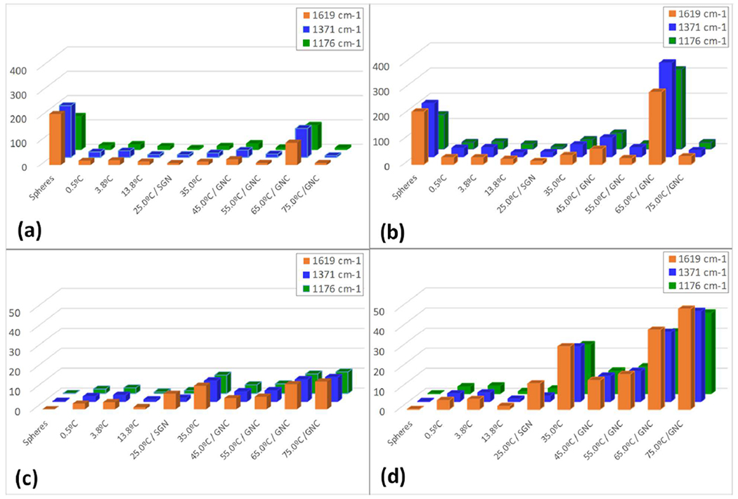
Compilation of calculated AEF values for the three analytical Raman bands of Malachite Green at 1619 cm−1, 1371 cm−1 and 1176 cm−1. (a) AEF of A-set samples without taking into account particle surface morphology, (b) AEF of A-set samples incorporating the normalized isoperimetric ratios, thus accounting for particle surface morphology. (c) AEF of B-set samples without taking into account particle surface morphology, (d) AEF of B-set samples incorporating the normalized isoperimetric ratios, thus accounting for particle surface morphology.
Similar analysis was also performed on the samples with equal nanoparticle concentrations in the aqueous suspensions, shown in Figures 8c and 8d. For this set of samples, the extent of surface enhancement is noticeably dependent on the synthesis temperature and as a result on nanoparticle surface morphology. These results demonstrate the synergistic importance of both nanoparticle concentration and nanoparticle morphology on their ability to provide surface-enhancement.
Other SERS studies conducted with nanoparticles possessing intricate surface features similarly found that increased surface morphologies increased the surface-enhancing potential of nanoparticles. This was attributed to the hot spots formed by the surface features of the nanoparticles, resulting in an increased density of local electromagnetic field lines [9, 10, 54, 55], as demonstrated by electron energy loss spectroscopy [56–58]. Hence, the observed SERS spectra for these nanoparticles can be predicted from their electron imaging based on similar work with other nanoparticles that possess a high degree of surface features [59, 60]. In light of previous work [51–53], the SERS activity of the nanoparticles presented in this work can be understood in terms of their increasingly complex nanoscale surface features, leading to an increased fractal character.
4. Conclusions
In this work, we examined the physical characteristics of novel gold nanoparticles having quasi-fractal morphology (GNC), focusing in particular on their efficacy as enhancers of Raman scattering signals. This highly branched nanoparticle morphology was achieved by the temperature modulation of the synthesis procedure previously used for the production of starlike gold nanoparticles (SGN). The kinetically-driven high degree of surface roughness in GNC was facilitated through a combination of the presence of hydroquinone as the reducing agent and higher synthesis temperatures. As a result of their high-curvature, sharp and irregular surface features, these nanoparticles exhibited marked enhancement of Raman signals of the reporter dye malachite green when compared with similar nanoparticles that possess less overall surface roughness, such as SGN. We also showed that despite the lower concentration of the GNC, the increased presence of sharp surface features provides more enhancement of Raman signals of the reporter dye when compared with similar concentrations of nanoparticles that possess lower degrees of surface features. Hence, we realized that the extent of the Raman signal enhancement by these quasi-fractal nanoparticles was not necessarily correlated to their surface plasmon resonance, but rather to the degree of their surface inhomogeneity
Two main phenomena were observed with the samples that were studied: (1) A decrease in nanoparticle concentration decreases the SERS activity, and (2) More complex surface morphology increases SERS activity. Hence, the SERS enhancement constitutes a combination of the effects of both on the morphology and on the concentration of the nanoparticle suspensions. Therefore, we have found that the calculated analytical enhancement factors (AEF), which represents the quantitative evaluation of the enhancement efficacy of the various nanoparticle samples, must include not only a concentration-dependent term, but also a morphology-dependent term. Based on our results, we concluded that the quasi-fractal nanoparticles might provide higher resolution and higher sensitivity for the detection of low concentration analyte molecules, and as such, may potentially be useful in imaging modalities that require high signal response and resolution. Their ability to couple with laser wavelengths that are non-resonant with their collective SPR allows for laser wavelength flexibility without need to tailor nanoparticle geometries for the required laser wavelength.
Supplementary Material
Acknowledgments
The authors thank Fran Adar of HORIBA for her insightful discussions, recommendations, and guidance. This research was funded in part through set-up funds from Stony Brook University to Prof. Tannenbaum and through the Stony Brook Scholars in Biomedical Sciences Program awarded to Dr. Darienzo during his PhD work in the Tannenbaum lab. This research used resources of the Center for Functional Nanomaterials, which is a U.S. DOE Office of Science Facility, at Brookhaven National Laboratory under Contract No. DE-SC0012704.
Footnotes
The authors declare that they have no competing financial interests.
References
- 1.Darienzo RE, Mironava T, Tannenbaum R, J. Nanosci. Nanotechnol, 2019, 19 (1–7), to appear. Preliminary version: https://chemrxiv.org/articles/Quasi-fractalGold Nanoparticles for Sers Effect of Nanoparticle Morphology and Concentration/7482098 [DOI] [PMC free article] [PubMed] [Google Scholar]
- 2.Fleischmann M, Hendra PJ, McQuillan AJ, Chem. Phys. Lett, 1974, 26, 163–166. 10.1016/0009-2614(74)85388-1. [DOI] [Google Scholar]
- 3.Jeanmaire DL, Van Duyne RP, J. Electroanal. Chem, 1977, 121, 1–20. 10.1016/S0022-0728(77)80224-6 [DOI] [Google Scholar]
- 4.Moskovits M, J. Chem. Phys, 1978, 69, 4159–4161. 10.1063/T437095 [DOI] [Google Scholar]
- 5.Haynes CL, McFarland AD, Van Duyne RP, Anal. Chem, 2005, 77, 338A–346A. 10.1021/ac053456d [DOI] [Google Scholar]
- 6.Liao PF, Wokaun A, J. Chem. Phys, 1982, 76, 751–752. 10.1063/1.442690 [DOI] [Google Scholar]
- 7.Moskovits M, Phys. Chem. Chem. Phys, 2013, 15, 5301–5311. 10.1039/C2CP44030J [DOI] [PubMed] [Google Scholar]
- 8.Kneipp K, Kneipp H, Itzkan I, Dasari RR, Feld MS, J. Phys. Condens. Matter, 2002, 14, R597–R624. 10.1088/0953-8984/14/18/202 [DOI] [Google Scholar]
- 9.Morasso C, Mehn D, Vanna R, Bedoni M, Forvi E, Colombo M, Prosperi D, Gramatica F, Mater. Chem. Phys, 2014, 143, 1215–1221. 10.1016/j.matchemphys.2013.11.024 [DOI] [Google Scholar]
- 10.Li J, Wu J, Zhang X, Liu Y, Zhou D, Sun H, Zhang H, Yang B, J. Phys. Chem. C, 2011, 115, 36303637 10.1021/jp1119074 [DOI] [Google Scholar]
- 11.Nehl CL, Liao H and Hafner JH, Nano Lett, 2006, 6, 683–688. 10.1021/nl052409y [DOI] [PubMed] [Google Scholar]
- 12.Link S, El-Sayed MA, J. Phys. Chem. B, 1999, 103, 4212–4217. 10.1021/jp984796o [DOI] [Google Scholar]
- 13.Santos J, Toma S, Corio P, Araki K, J. Ram. Spectrosc, 2017, 48, 1190–1195. 10.1002/jrs.5203 [DOI] [Google Scholar]
- 14.Schulz F and Homolka T and Bast NG{\’u}s and Puntes V and Weller H and Vossmeyer T, Langmuir, 2014, 30, 10779–10784. 10.1021/la503209b [DOI] [PubMed] [Google Scholar]
- 15.McCreery RL, Raman Spectroscopy for Chemical Analysis, in Chemical Analysis: A Series of Monographs of Analytical Chemistry and its Applications, Winefordner JD, Ed., Wiley Interscience; 2000, Vol. 157, p. 63–64. [Google Scholar]
- 16.Le Ru EC, Blackie E, Meyer M, and Etchegoin PG, J. Phys. Chem. C, 2007, 11, 13794–13803. 10.1021/jp0687908 [DOI] [Google Scholar]
- 17.José-Yacamán M, Gutierrez-Wing C, Miki M, Yang D-Q, Piyakis KN, Sacher E, J. Phys. Chem. B 2005. 109 19 9703–9711. 10.1021/jp0509459 [DOI] [PubMed] [Google Scholar]
- 18.Link S, Wang ZL, El-Sayed MA, J. Phys. Chem. B 2000. 104 33 7867–7870. 10.1021/ip0011701 [DOI] [Google Scholar]
- 19.Hua Y, Chandra K, Dam DHM, Wiederrecht GP, Odom TW, J. Phys. Chem. Lett 2015. 6 (24) 4904–4908. 10.1021/acs.ipclett.5b02263 [DOI] [PubMed] [Google Scholar]
- 20.Vigderman L, Zubarev ER, Chem. Mater 2013, 25, 1450–1457. 10.1021/cm303661d [DOI] [Google Scholar]
- 21.Lim B, Xia Y, Angew. Chem. Int. Ed 2011, 50, 76–85. 10.1002/anie.201002024 [DOI] [PubMed] [Google Scholar]
- 22.Polte J, Erler R, Thunemann AF, Sokolov S, Torsten Ahner T, Rademann K, Emmerling F, Kraehnert R, ACS Nano 2010, 4 (2), 1076–1082. 10.1021/nn901499c [DOI] [PubMed] [Google Scholar]
- 23.Polte J, Torsten Ahner T, Delissen F, Sokolov S, Emmerling F, Thünemann AF, Kraehnert R, J. Amer. Chem. Soc 2010, 132 (4), 1296–1301. 10.1021/ja906506j [DOI] [PubMed] [Google Scholar]
- 24.Gentry ST, Fredericks SJ, Krchnavek R, Langmuir 2009, 25 (5), 2613–2621. 10.1021/la803680h [DOI] [PubMed] [Google Scholar]
- 25.Yuan H, Khoury CG, Hwang H, Wilson CM, Grant GA, Vo-Dinh T, Nanotechnology 2012, 23 (7), 075102 10.1088/0957-4484/23/7/075102 [DOI] [PMC free article] [PubMed] [Google Scholar]
- 26.Sajitha M, Vindhyasarumi A, Gopiab A, Yoosaf K, RSC Adv. 2015, 5, 98318–98324. 10.1039/C5RA19098C [DOI] [Google Scholar]
- 27.Morasso C, Picciolini S, Schiumarini D, Mehn D, Ojea-Jimeriez I, Zanchetta G, Vanna R, Bedoni M, Prosperi D, Gramatica F, J. Nanopart. Res 2015, 17, 330 10.1007/s11051-015-3136-9 [DOI] [Google Scholar]
- 28.Tran M, DePenning R, Turner M, Padalkar S, Mater. Res. Express, 2016, 3, 105207 10.1088/2053-1591/3/10/105027 [DOI] [Google Scholar]
- 29.Su D, Dou S, Wang G, NPG Asia Materials 2015, 7, e155 10.1038/am.2014.130 [DOI] [PMC free article] [PubMed] [Google Scholar]
- 30.Kundu S, J. Mater. Chem. C 2013, 1 (4) 831–842. 10.1039/C2TC00315E [DOI] [Google Scholar]
- 31.Kundu S, Jayachandran M, RSC Adv. 2013, 3 (37) 16486–16498. 10.1039/C3RA42203H [DOI] [Google Scholar]
- 32.Patungwasa W, Hodak JH, Mater. Chem. Phys 2008, 108 (1), 45–54. 10.1016/j.matchemphys.2007.09.001 [DOI] [Google Scholar]
- 33.Shields SP, Richards VN, Buhro WE, Chem. Mater 2010, 22 (10), 3212–3225. 10.1021/cm100458b [DOI] [Google Scholar]
- 34.Bastds NG, Comenge J, Puntes V, Langmuir, 2011,27, 11098–11105. 10.1021/la201938u [DOI] [PubMed] [Google Scholar]
- 35.Shajari D, Bahari A, Gill P, Mohseni M, Opt. Mater, 2017, 64, 376–383. 10.1016/j.optmat.2017.01.004 [DOI] [Google Scholar]
- 36.Babaei F, Javidnasab M, Rezaei A, Plasmonics, 2018, 13, 1–7. 10.1007/s11468-018-0803-6 [DOI] [Google Scholar]
- 37.Bakr OM, Wunsch BH, Stellacci F, Chem. Mater, 2006, 18, 3297–3301. 10.1021/cm060681i [DOI] [Google Scholar]
- 38.Niu J, Zhu T, Liu Z, Nanotechnology 2007, 18, 325607 10.1088/0957-4484/18/32/325607 [DOI] [Google Scholar]
- 39.Nehl CL, Hafner JH, J. Mater. Chem 2008, 18, 2415–2419. 10.1039/B714950F [DOI] [Google Scholar]
- 40.Hao E, Bailey RC, Schatz GC, Hupp JT, Li S, Nano Lett. 2004, 4 (2), 327–330. 10.1021/nl0351542 [DOI] [Google Scholar]
- 41.Li N, Zhao P, Astruc D, Angew. Chem. Intl. Ed 2014, 53, 1756–1789, 10.1002/anie.201300441 [DOI] [PubMed] [Google Scholar]
- 42.Freger V, Ben-David A, Anal. Chem 2005, 77(18), 6019–6025. 10.1021/ac050689w [DOI] [PubMed] [Google Scholar]
- 43.Kuncicky DM, Christensen SD, Velev OD, Appl. Spectrosc 2005, 59 (4), 401–409. http://as.osa.org/abstract.cfm?URI=as-59-4-401 [DOI] [PubMed] [Google Scholar]
- 44.Ha Y, Katz LE, Liljestrand HM, Environ. Sci. Technol, 2015, 49 (24), 14546–14553. 10.1021/acs.est.5b03339 [DOI] [PubMed] [Google Scholar]
- 45.Lei S, Tahara K, De Schryver FC, Van der Auweraer M, Tobe Y, De Feyter S, Angew. Chem. Int. Ed 2008, 47 (16), 2964–2968. 10.1002/anie.200705322 [DOI] [PubMed] [Google Scholar]
- 46.Praetorius A, Tufenkji N, Goss K-U, Scheringer M, von der Kammerd F, Elimelech M, Environ. Sci.: Nano 2014, 1 (4), 317–323. 10.1039/C4EN00043A [DOI] [Google Scholar]
- 47.Stobiecka M, Hepel M, Biomaterials 2011, 32 (12) 3312–3321. 10.1016/j.biomaterials.2010.12.064 [DOI] [PubMed] [Google Scholar]
- 48.Ko H, Singamaneni S, Tsukruk VV, Small 2008, 4 (10), 1576–1599. 10.1002/smll.200800337 [DOI] [PubMed] [Google Scholar]
- 49.Cialla D, März A, Böhme R, Theil F, Weber K, Schmitt M, Popp J, Anal. Bioanal. Chem 2012, 403 (1), 27–54. 10.1007/s00216-011-5631-x [DOI] [PubMed] [Google Scholar]
- 50.Gu GH and Suh JS, J. Raman Spectrosc 2010, 41,624–627. 10.1002/jrs.2487 [DOI] [Google Scholar]
- 51.Mayer KM and Hafner JH, Chem. Rev 2011, 111, 3828–3857. 10.1021/cr100313v [DOI] [PubMed] [Google Scholar]
- 52.Willets KA and Van Duyne RP, Annu. Rev. Phys. Chem 2007, 58, 267–297. 10.1146/annurev.physchem.58.032806.104607 [DOI] [PubMed] [Google Scholar]
- 53.Eustis S and El-Sayed MA, Chem. Soc. Rev 2006, 35, 209–217. 10.1039/B514191E [DOI] [PubMed] [Google Scholar]
- 54.Pazos-Pérez N, Barbosa S, Rodríguez-Lorenzo L, Aldeanueva-Potel P, Pérez-Juste J, Pastoriza-Santos I, Alvarez-Puebla RA, Liz-Marzán LM, J. Phys. Chem. Lett 2010, 1,24–27. 10.1021/jz900004h [DOI] [PubMed] [Google Scholar]
- 55.Rodríguez-Lorenzo L, Álvarez-Puebla RA, Pastoriza-Santos I, Mazzucco S, Stéphan O, Kociak M, Liz-Marzán LM, García de Abajo FJ, J. Am. Chem. Soc 2009. 13 (11) 34616–34618. 10.1021/ja809418t [DOI] [PubMed] [Google Scholar]
- 56.Nelayah J, Kociak M, Stéphan O, Javier García de Abajo F, Tencé M, Henrard L, Taverna D, Pastoriza-Santos I, Liz-Marzán LM, Colliex C, Nat. Phys, 2007, 3, 348–353. 10.1038/nphys575 [DOI] [Google Scholar]
- 57.Hohenester U, Ditlbacher H, Krenn JR, Phys. Rev. Lett, 2009, 103, 106801 10.1103/PhysRevLett.103.106801 [DOI] [PubMed] [Google Scholar]
- 58.Barrow SJ, Rossouw D, Funston AM, Botton GA, Mulvaney P, Nano Lett, 2014, 14, 3799–3808. 10.1021/nl5009053 [DOI] [PubMed] [Google Scholar]
- 59.Lv W, Gu C, Zeng S, Han J, Jiang T, Zhou J, Biosensors 2018, 8, 113, 10.3390/bios8040113 [DOI] [PMC free article] [PubMed] [Google Scholar]
- 60.Indrasekara ASDS, Meyers S, Shubeita S, Feldman LC, Gustafsson T, Fabris L, Nanoscale 2014, 6 (15) 8891–8899. 10.1039/C4NR02513J [DOI] [PubMed] [Google Scholar]
Associated Data
This section collects any data citations, data availability statements, or supplementary materials included in this article.


