Abstract
Despite advances in biomaterials research, there is no ideal device for replacing weight-bearing soft tissues like menisci or intervertebral discs due to poor integration with tissues and mechanical property mismatch. Designing an implant with a soft and porous tissue-contacting structure using a material conducive to cell attachment and growth could potentially address these limitations. Polycarbonate urethane (PCU) is a soft and tough biocompatible material that can be 3D printed into porous structures with controlled pore sizes. Porous biomaterials of appropriate chemistries can support cell proliferation and tissue ingrowth, but their optimal design parameters remain unclear. To investigate this, porous PCU structures were 3D-printed in a crosshatch pattern with a range of in-plane pore sizes (0 to 800 μm) forming fully interconnected porous networks. Printed porous structures had ultimate tensile strengths ranging from 1.9 – 11.6 MPa, strains to failure ranging from 300 – 486%, Young’s moduli ranging from 0.85 to 12.42 MPa, and porosity ranging from 13 – 71%. These porous networks can be loaded with hydrogels, such as collagen gels, to provide additional biological support for cells. Bare PCU structures and collagen-hydrogel-filled porous PCU support robust NIH/3T3 fibroblast cell line proliferation over 14 days for all pore sizes. Results highlight PCU’s potential in the development of tissue-integrating medical implants.
Keywords: 3D-printing, porous, polycarbonate urethane, hydrogel, collagen
Introduction
There is great interest in the fabrication of devices that can better integrate with host tissues, a strategy that has already been proven useful in orthopedic [1], maxillofacial [2], cardiovascular [3] and dental implants [4]. Some devices like catheters or external fixators should be in contact with the body for as little time as possible; many other devices, including hip and knee implants, stents, and fusion cages become a permanent part of a patient’s anatomy. Achieving an appropriate response from host tissues to implanted materials is key for their success, with failure having the potential to be catastrophic [5]. This is exemplified by poor integration of tissue into implants used for cervical disc replacement. Migration or instability of the implant is the most common cause of reoperation for this procedure, accounting for 19% of cases that result in removal of the implant and subsequent anterior cervical decompression and fusion [6]. Compared to primary spinal fusion, a revision of disc replacement to spinal fusion is technically more difficult and results in increased cost, length of stay, infection risk, neurologicalcomplications and dysphagia [7].
Lack of integration is not the only limitation of implants, particularly when trying to replace or repair weight-bearing soft tissues like hyaline cartilage or spinal disks. Materials currently used for this goal, such as polyether ether ketone [8], ultra-high molecular weight polyethylene [9] and titanium [10] are much stiffer than these soft tissues. This produces a mismatch in mechanical properties and can lead to degradation of surrounding structures; subsidence of disc replacement devices into the adjacent vertebrae is a well-known example of complications arising from mechanical mismatch [11]. A porous structure made of a softer material would be an ideal tool to overcome both problems, as it could facilitate cellular ingrowth and tissue formation [12], and could simultaneously avoid mechanical stiffness mismatch. Nevertheless, the use of soft porous structures is still limited by a lack of adequate strength and ill-defined design parameters to guide pore network geometry [13]. Controversy exists with respect to how porosity, pore size and degree of pore interconnectivity impacts cellular behavior; past research has yielded inconclusive or contradictory results. For example, reported optimal average pore size values for cell proliferation range from 20 to 1500 μm [14]. This disparity in results may be caused by poorly controlled pore size and interconnectivity. Most techniques used to produce pores, such as salt leaching [15] and gas foaming [16] result in porous materials with a wide range of pore sizes and interconnectivity, limiting their utility for the elucidation of the relationship between design parameters and cellular response. New processing methods capable of producing tightly controlled architectures are valuable tools that overcome this problem [13].
One such method is 3D-printing, also referred to as additive manufacturing. Customization, reproducibility, rapid prototyping and production of complex geometries, both internal and superficial, make it ideal for manufacturing porous materials with narrow distributions of pore sizes and well-defined interconnectivity [17] [18]. This uniformity is key to fully evaluate the effect these features have on cell behavior. Furthermore, 3D-printing is compatible with a variety of biomaterials, including polylactic acid [18], polycaprolactone [19], titanium [20] and, as recently described, polycarbonate urethane (PCU) [21].
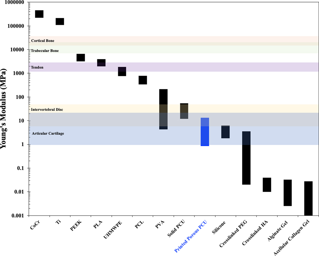
PCU is a polymer with a combination of biological, chemical and mechanical properties that make it appealing for certain medical applications [22]. PCU is currently used in orthopedic applications including spinal disk replacements along with meniscus and acetabular cup replacements [23]. This polymer fills a niche in medicine not currently occupied by other materials; metals and hard plastics, such as titanium and polyether ether ketone, are commonplace [24] but their high elastic modulus limits their applicability in softer musculoskeletal tissues like cartilage, tendons, and spinal discs [25]. PCU is both strong and soft [23]; its lower modulus of elasticity brings it closer to these soft tissues, being the strongest synthetic elastomer already implanted in the human body [26]. By comparison, PCU has only half the strength of PEEK but a modulus that is 300 times lower. This can be beneficial, as matching the host tissue mechanical properties can help diminish stress shielding and stress concentrations at the device-tissue interface (Figure 1).
Figure 1.
Young’s modulus of various relevant biomaterials and tissues: cobalt chrome (CoCr) [10], titanium alloy (Ti) [10] polyether ether ketone (PEEK) [8], polylactic acid (PLA) [30], ultra-high-molecular-weight polyethylene (UHMWPE) [9] polycaprolactone (PCL) [31], polyvinyl acetate (PVA) [32], solid PCU (95a) [26], silicone [33], polyethylene glycol (PEG) [34], crosslinked hyaluronic acid (HA) [35], articular cartilage [36], intervertebral disc [37], tendon [38] [39], trabecular bone [40] and cortical bone [41].
Motivated by PCU’s potential as a platform for soft tissue medical devices, we evaluated 3D-printed porous PCU’s ability to support cell attachment and proliferation, and sought to optimize its design parameters. We produced several different porous PCU structures with a range of pore sizes, from 100 to 800 μm, and assessed effects on cell proliferation and distribution. Importantly, all structures had a fully interconnected pore network and narrowly distributed pore sizes. We hypothesized that cell proliferation would be improved by combining the synthetic material with natural products found in the extracellular matrix, such as collagen. Filling the void space of our porous PCU with a collagen hydrogel (Figure 2) may provide cell adhesion cues [27], and create a more physiologically relevant 3D environment for cells to thrive in contrast to the two-dimensional regime that they experience when growing on the surface of a material [28].
Figure 2.
Production of PCU porous structures with a range of tightly controlled in plane pore size (IPPS) (100, 200, 400, 600 or 800 μm) by fused deposition modeling, a 3D printing technique. Cell proliferation, distribution and viability for every IPPS were studied for two different groups. One group was seeded with cells suspended in an aqueous solution. The other group was seeded with cells suspended in a collagen solution, which was thermally gelled inside the porous structure after seeding.
On their own, hydrogels have mechanical properties that are insufficient to meet certain demands of musculoskeletal tissues. On the other hand, PCU, while biomechanically compatible has not been extensively studied as a cell supportive material. Therefore, a composite of both materials might provide the mechanical support for functional replacement of damaged tissue while creating an optimal environment for its regeneration. Nevertheless, a conflict arises when considering this hybrid system, as increasing the proportion of void space in the construct comes at the cost of diminished mechanical properties. Increasing the porosity of PCU, while not impacting tensile failure strain, decreases the tensile failure stress and stiffness of the structure [29]. Conversely, decreasing the porosity can limit both mass transport and the ingrowth of tissue. With this in mind, we sought to understand this trade-off between biological activity and mechanical properties, both of which are essential for engineering an ideal platform for tissue integration.
Materials and Methods
PCU
95A PCU pellets (Carbothane AC-4095, Lubrizol) were extruded into 3 mm filament following manufacturer’s instructions. The filament was baked at 105 °C and 25 in Hg vacuum for 24 h to remove moisture.
Printing PCU porous structures
105 × 55 × 1.66 mm rectangular prisms were modeled in Fusion360. The .stl file was exported into Simplify3D to generate gcode. All structures were printed on the same Taz 5 printer (Lulzbot) with a 0.4 mm nozzle. Bed temperature was set to 40 °C, and printing speed was set to 360 mm/min. The first layer was designed as a solid (representing a macroscopic medical device) and printed in a diagonal pattern. Porosity was created in the next 4 layers using a rectilinear infill pattern (representing a porous outer layer for a medical device). A strut size of 400 μm was created by setting extrusion width to 400 μm and extrusion multiplier to 0.75. Layer height was set to 333 μm to ensure proper adhesion between layers. The infill percentage was tuned to create the varying in-plane pore size (IPPS), defined as the minimum distance between struts on a XY plane. To create the 0 μm, 100 μm, 200 μm, 400 μm 600 μm and 800 μm IPPS used in this study, the infill percentage was set to 100, 80, 67, 50, 40 and 33 % respectively. The nozzle temperature was tuned to optimize printing for each group. For the 0 μm group, the nozzle was set to 220 °C. For the 100 μm, and 200 μm group, the nozzle was set to 220 °C for the first layer and 215 °C for the following four layers. For the 400 μm, 600 μm and 800 μm group, the nozzle was set to 220 °C for the first layer and 212 °C for the following four layers. A hotter nozzle for the first layers helps the struts fuse to make a solid sheet and a cooler nozzle prevents the struts from sagging between larger gaps. The edge of porous sheet was trimmed, and the sheet was cut into 1 cm squares.
Light Microscopy and Micro-CT characterization of sample
Representative samples from each group were analyzed with Olympus SZ61 microscope and pictures were taken with Olympus SC50 camera. A representative sample from each group was saved for a batch micro-CT scan (Nikon XTH 225 ST). The samples were secured to plastic containers with double sided tape. The plastic containers were stacked in the scanner. The power for X rays was set to 105 kV and current was set to 119 uA. Raw data was reconstructed using CT Pro 3D software (Nikon) and analyzed using AvizoLite (FEI). Orthogonal slices were created on the YZ and XY plane. IPPS was determined by measuring the shortest distance between struts on the XY plane. Five measurements were made for each porous layer. 3D reconstructions shown in Figure 2 were made by limiting the volume of interest to exclude the tape and plastic container. The volume was then turned into surface to measure solid volume and surface area of the structure. The bottom of the porous structure was not included in surface area calculation as a cell would not have access to it. Void volume was calculated by subtracting the volume of the smallest rectangular prism that can encompass the porous part of the structure by the measured solid volume.
Tensile Testing
Samples shaped as dog bones were printed to match the pore geometry of each group of porous PCU structures. The maximum length x width x height of dog bones were 63.5 × 9.5 × 2 mm respectively. The minimum length x width x height at gauge was 4.9 × 3.2 × 2 mm. (Supplementary Figure 1a). Printing parameters were the same except dog bones had no solid layer, and therefore the entire print was done at one nozzle temperature and strut orientation was set to 45°and −45° relative to the long axis of the dog bone (Supplementary Figure 1b). Tensile testing was done to create stress-strain curves for each group (n=3). The gauge section of each dog bone was measured with calipers before testing. Dog bones were clamped to test frame (TR830) in a 37°C water bath. Samples were strained at a rate of 10 mm min-1 until failure. Ultimate tensile strength (UTS) was determined by the maximum stress the sample withstood. Strain to failure (STF) was determined to be the maximum strain of the sample before it failed. Young’s Modulus was determined by calculating the slope of the least squares regression line of the stress-strain curve from 5% to 10% strain. In order to make mechanical properties data applicable to a broad range of loading mechanism, the dog bones were tested in their weakest configuration. The internal crosshatch pattern was oriented at 45° and −45° so there were no struts in line with the force applied (Supplementary Figure 1b).
Cell culture
NIH 3T3 fibroblasts were cultured at 37 ºC and 5% CO2 in Dulbecco’s Modified Eagle’s Medium (DMEM, 4.5 g/L D-Glucose, Corning) supplemented with fetal bovine serum (final concentration of 10% v/v) (Atlanta Biologicals) and penicillin/streptomycin (final concentration of 1% v/v) (VWR). Cells were grown in 75 cm2 culture flasks and passaged at 70–80% confluency using 0.25% trypsin and 2.21 mM EDTA (Corning).
Seeding of the porous PCU structures
PCU squares were sterilized via autoclaving, transferred to a 24-well plate, soaked in 70% ethanol (1 h) and washed twice with deionized water (30 min each). NIH 3T3 cells at the logarithmic growth phase were detached using 0.25% trypsin and 2.21 mM EDTA (Corning), centrifuged at 200 g for 5 min, resuspended in culture medium and counted.
For the collagen-PCU group, a 2 mg ml-1 solution of bovine type I collagen was prepared from a stock solution of 3 mg ml-1 (PureCol®, Advanced BioMatrix) according to the manufacturer’s instructions. 1 part of sterile 10X phosphate buffer saline (PBS) was added to 8 parts of 3 mg ml-1 collagen solution. The pH of the solution was then neutralized using 1 part sterile 0.1 M NaOH. Final volume was adjusted with the appropriate amount of cell suspension and culture medium to obtain a final density of 106 cells/ml. Immediately after the washing steps, 100 μl of cell suspension was pipetted onto each structure. Gelation was achieved by incubation at 37 ºC for 90 min. Finally, they were transferred to a new 24-well plate, covered with complete culture medium and kept in a 37 ºC, 5% CO2 incubator.
Another cell suspension was adjusted to a final density of 106 cells ml-1 using sterile 1X PBS. 100 μl of the adjusted suspension was pipetted onto the structures to obtain the bare PCU group, which was treated analogously to the collagen-PCU group.
Cell proliferation
The content of dsDNA in the structures was used as a marker of cell proliferation. Samples were washed twice with pre-warmed 1X PBS and incubated for 90 min at 37 ºC, in a 0.5 mg ml-1 solution of collagenase (C2674, Sigma) prepared in 1x PBS containing 0.36 mM Ca2+. The resulting cell suspension was collected, and the structures were washed twice with 1X PBS. The cell suspension obtained from the digestion and washing steps was centrifuged, and the cells were resuspended in 1 ml of sterile 1X PBS. Samples obtained from the previous step underwent three freeze-thaw cycles (−80 ºC freezer for 90–120 min and 37 ºC water bath for 10–15 min) for cell lysis. A PicoGreen® (ThermoFisher Scientific) assay was performed to quantify the amount of dsDNA in the structure, according to the manufacturer’s instructions. Standards were created by serial dilution of lambda phage DNA included in the PicoGreen® assay kit. Fluorescence intensity was measured using a TECAN M200 INFINITE plate reader (ex/em 485/535 nm).
Fluorescence Staining
After the corresponding time in culture, media was removed and both groups were incubated in Live/Dead staining solution (ThermoFisher Scientific) prepared according to manufacturer’s instructions. A solution of 4 μM ethidium homodimer-1 and 2 μM calcein-AM in sterile 1X PBS was prepared (stock solution concentrations: 4 mM and 2 mM, respectively). Samples were incubated in this solution for 40 minutes at room temperature and imaging was performed using a Zeiss Axiovert 135 epifluorescence microscope (ex/em: Calcein AM 480/535 nm (Live); Ethidium homodimer, 500/645 nm (Dead)).
Results
Production and Characterization of Porous PCU
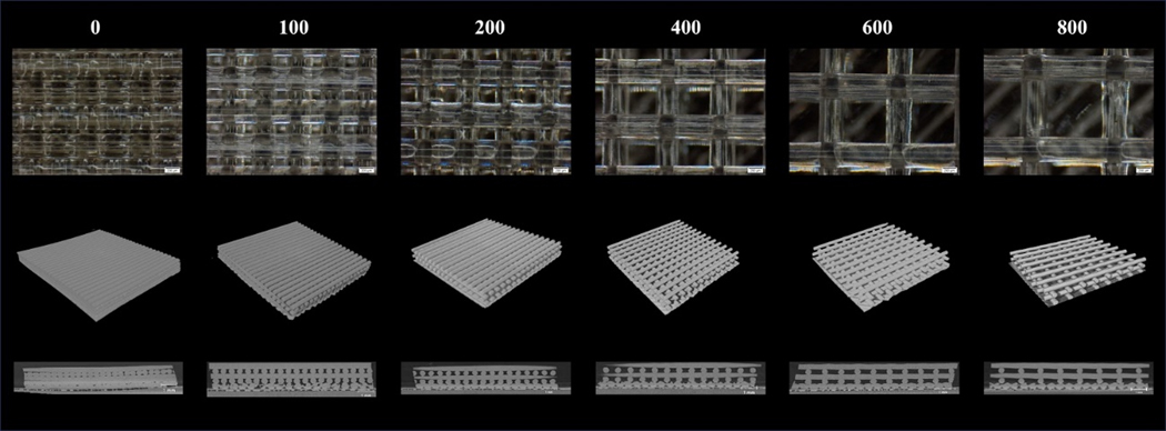
Porous PCU was successfully printed in a crosshatch pattern. Light microscopy showed struts were printed consistently and that the IPPS were reliably varied from 100 to 800 μm (Figure 3a). The 3D reconstruction of the porous structures demonstrated that the printed pattern created an interconnected porous network with precisely engineered geometries (Figure 3b). The YZ section from the micro-CT scan illustrate that the struts were extruded on their defined plane without sagging into the pore space (Figure 3c).
Figure 3.
Representative images of porous PCU with increasing IPPS. a) Image of porous structures taken with a light microscope. b) 3D reconstruction of the porous structures from a micro-CT scan. c) Cross section of the porous structures on the YZ plane.
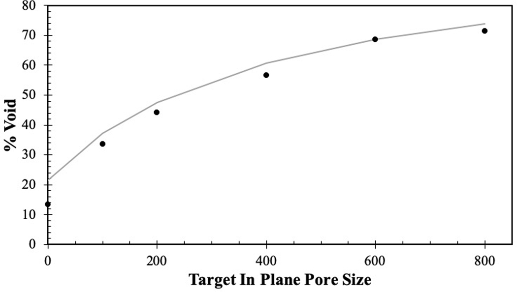
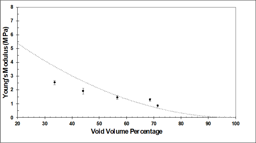
Quantitative measures of pore geometries were obtained via micro-CT. The measurements on PCU porous structures demonstrated that printed IPPS were relatively precise and accurate (Table 1). The range of the 95% confidence interval was below 30 μm for each group. The printed IPPS values were slightly larger than intended; however, the target size was within 15 μm of the 95 % confidence interval for each group. The void volume fraction measured by micro-CT showed that as IPPS increased, the void volume fraction increased as expected (Table 1). The theoretical void volume fraction was calculated by modeling the struts as an oval rod with the major axis equal to extrusion width and minor axis equal to layer height. Using this model, experimentally measured void volume fractions were found to be in good agreement with the theoretical calculations (Figure 4).
Table 1.
Measurements of IPPS, void volume fraction and available surface area taken from micro-CT data. Available surface area per volume refers to surface area that cells could grow on divided by volume or rectangular prism porous region occupies. It excludes the bottom of the structure that contacts bottom of well plate and is inaccessible to cells.
| Target In Plane Pore Size (IPPS) [μm] | 95 % Confidence Interval of Measured In Plane Pore Size (IPPS) [μm] | Void Volume Fraction [%] | Available Surface Area per Volume [mm2 mm−3] |
|---|---|---|---|
| 0 | [7.17 – 23.4] | 13.3 | 2.57 |
| 100 | [101.50 – 116.97] | 33.56 | 5.67 |
| 200 | [195.56 – 217.93] | 44.11 | 4.44 |
| 400 | [382.96 – 403.33] | 56.56 | 3.95 |
| 600 | [601.69 −621.60] | 68.59 | 3.03 |
| 800 | [811.75 – 828.95] | 71.44 | 2.95 |
Figure 4.
Illustration of how the theoretical void percentage compares (gray curve) to the experimentally measured void fraction (black dots).
Mechanical Testing
Representative stress-strain curves showed a clear difference in mechanical properties between groups (Figure 5). The peak of each curve was used to determine the Ultimate Tensile Strength (UTS) and Strain to Failure (STF) for each group of samples. Young’s modulus was determined by calculating the slope of the line of best fit between 5% and 10% strain. UTS, STF and Young’s modulus were compared to both the IPPS and void volume fractions. These data cannot determine if changes in mechanical properties were primarily due to pore size or void volume fraction as these two inputs are a function of each other.
Figure 5.
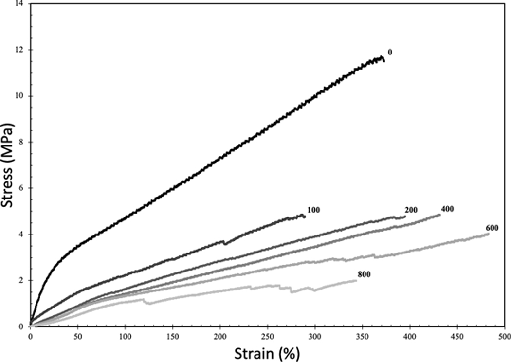
Representative stress-strain curves of 3D-printed samples created with the same crosshatched geometry as the porous structures. Number at the end of each curve represents the target IPPS.
There was a sharp decrease in strength when separation between struts was introduced, as expected (Figure 5). By changing porosity, UTS varied 5-fold among the different groups tested (Figure 6a). In contrast, STF did not vary significantly between the different groups (Figure 6b). The extreme ends of the porous groups, 100 and 800 μm, exhibited the lowest STF. The 100 and 800 μm pore samples, with the lowest STF, were the most difficult to print. In the case of the 100 μm porous sample, the UTS is clipped by the early strain to failure, as this stiffer sample was headed towards a higher UTS in theory. The lower than expected values for UTS and STF in the 100 μm porous sample are likely due to limitations to the printing process and not pore geometry. Similar to UTS, the Young’s modulus decreased sharply after strut separation was introduced but exhibited a gradual decline as porosity increased (Figure 6c). By tuning the modulus over this wide range, the stiffness of the implant can be modified to match that of the original tissue. By doing so, implants mitigate the problem of stress shielding and stress concentrations. A comparison of Young’s modulus for various materials used in healthcare shows PCU stiffness is in the range of cartilage and intervertebral discs (Figure 1b). Silicone also falls into this range, but its weak UTS makes PCU a preferable material candidate. Reported UTS of solid silicone in commercial maxillofacial prosthetic devices is 2.53–8.36 MPa [42]. Tensile testing of solid, injection molded PCU in the literature showed UTS and Young’s modulus reaching 56 MPa and 19 MPa respectively [21]. The decrease in mechanical properties in this study was due to void space in the samples. Despite the IPPS being near 0 for the strongest group, there was 13.3% void space as printing parameters were not optimized to create a solid part. The struts were printed as ovals with the widest dimension used to determine IPPS leaving void space above and below the measured plane.
Figure 6.
a) UTS compared to IPPS. b) STF of compared to IPPS. c) UTS compared to void volume fraction. Results are presented as the mean± standard error (S.E.) (n=3 per group).
Cell Proliferation in Porous PCU structures
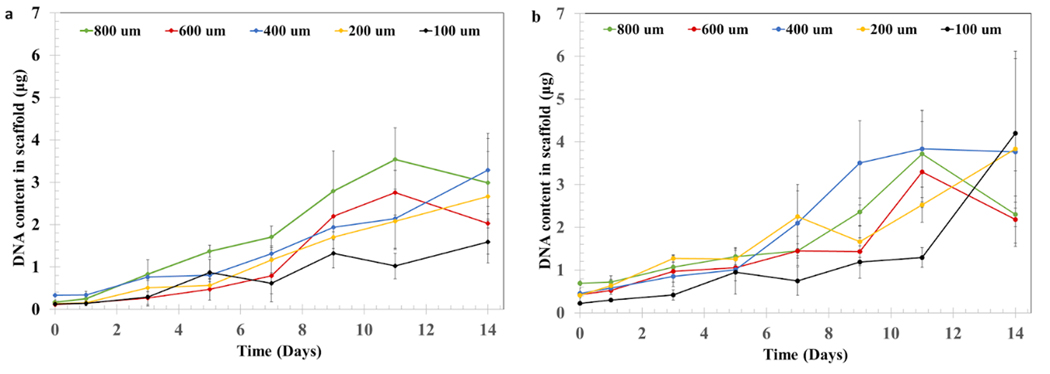
Porous PCU was seeded with cells at a density of 106 cells ml-1, either in an aqueous suspension (Figure 7a) or suspended in type I collagen (2 mg ml-1) (Figure 7b). NIH/3T3 fibroblast proliferation was evaluated by measuring the DNA content in the structure over 14 days of culture. Our results indicate that all conditions supported robust cell proliferation. Interestingly, we did not find marked differences in the content of DNA between the bare PCU and the structures filled with collagen. Similarly, we did not find a clear quantitative effect of IPPS on cell proliferation.
Figure 7.
Cell proliferation assay of NIH/3T3 cells. DNA content in the porous PCU structures was measured for a) cells cultured on bare PCU or b) cells cultured on PCU combined with a collagen hydrogel. DNA content in the structures at days 0, 1, 3, 5, 7, 9, 11 and 14 was measured using a PicoGreen assay. Results are presented as the mean± S.D (n=4).
Cell Distribution and Viability in porous PCU structures
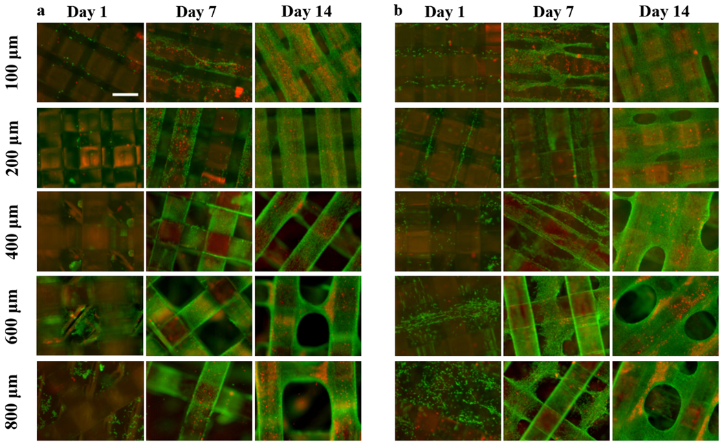
Live/Dead staining was used to determine the biocompatibility of the porous structures and the distribution of NIH/3T3 cells inside them. Cell-loaded porous structures were incubated with calcein AM, which labels live cells (green fluorescence) and ethidium bromide, which is a membrane impermeable dye and thus can only label cells that have sustained membrane damage (red fluorescence). While the quantitative DNA concentration data did not show marked differences between conditions, fluorescence staining demonstrates qualitative differences in cell distribution depending on IPPS and the seeding method.
Bare PCU supported cell growth, with cells covering the material by day 14 and cellular bridges connecting the struts in the porous structures with the smallest IPPS (Figure 8a). The same situation was found for the collagen-PCU system, with cells growing throughout the interconnected collagen-filled space by day 7 (Figure 8b). Marked cellular bridging between struts was visible by day 14, being present for all IPPSs. Significant bridging was only present for the collagen-filled, cell-seeded structures. Bridging or any similar defects was never observed when imaging acellular scaffolds, so we are certain that the cells are bridging and not the struts. Cell death was visually more prominent in the bare PCU group, which showed more necrotic zones than in the collagen-PCU combined material.
Figure 8.
Representative Live/Dead (Green = calcein AM in live cells, red = ethidium homodimer in dead cells)) staining images of NIH/3T3 cells, performed at days 1, 7 and 14 for a) bare and b) collagen filled porous structures, illustrating differences in cell distribution between groups. Scale bar = 400 μm.
Discussion
In this work, we successfully 3D printed homogeneously porous PCU structures with a wide range of IPPS. Four-layered porous structures with IPPSs of 100, 200, 400, 600 and 800 μm were produced. All conditions had tightly controlled IPPS and a completely interconnected porous network across the layers. This is the first report that studies the biological effect of 3D printed PCU structures with tightly controlled geometry. PCU offers several potential advantages over currently used materials for soft tissue repair and replacement. Stiffness mismatch between the device and host tissues as well as stress shielding are detrimental to the performance of orthopedic devices. These factors can lead to stress concentration at the device-tissue interface and a perturbation in the normal loading of surrounding bone, which ultimately leads to loss of bone density [43][44]. Subsidence of metallic intervertebral disc replacement devices, where the implant penetrates the lower vertebral body, is a well-known complication that can arise from stiffness mismatch [45]. Reported rates of subsidence can be as high as 21% [46], underscoring the need for better options in weight-bearing soft tissue replacement materials. The low elasticity modulus of PCU can help ameliorate these problems. Unlike other materials with low elasticity modulus, such as silicone, PCU has high strength [33]. Moreover, it can withstand physiologically relevant loads for several million loading cycles with reduced wear compared to the widely used UHMWPE [47] [48]. We were successful in 3D-printing a device with tunable mechanical properties by varying IPPS, effectively providing a way to match the stiffness of native weight-bearing soft tissues. The decrease in stiffness seen as the void volume increased is consistent with the literature. There are scaling laws that describe how the mechanical properties of open cell foams change with porosity. The scaling equation for Young’s modulus is [49]:
E is the theoretical Young’s modulus, S is the scaling factor for different materials that can range from 0.1 to 4, EEss is the Young’s modulus of a solid material and 𝑉𝑉𝑓𝑓is the void volume fraction. Figure 9 shows the theoretical Young’s modulus for the porous PCU constructs. The equations assumes the sample is an ideal foam with uniformly disturbed pore space with perfect isotropy. The deviations from the curve are due to PCU constructs having non-random and geometrically defined pores, and being manufactured with potential printing defects. Furthermore, the PCU constructs are anisotropic due to specific strut orientation and were tested in the worst-case scenario where none of the struts were in line with tension force.
Figure 9:
Comparison of experimentally determined Young’s modulus for 3D printed PCU constructs with varying porosity (solid dots) compared to the theoretical relationship between Young’s modulus and porosity for an ideal open cell foam with a scaling factor set at S=.3 (dotted line). Experimental results are presented as the mean± standard error (S.E.) (n=3 per group).
As we show here, 3D printing allows for the manufacturing of devices with porous outer layers that can be filled with hydrogel. This can potentially be useful for improving the integration of the device with host tissues and decrease the risk of fusion failure, which is a known limitation of the solid PCU currently used in orthopedics [50]. However, the effect of pore size in macroporous structures (pore sizes of tens to hundreds of microns) on cell behavior is still unclear, with the notion of an optimal pore size being based on studies that used systems with poorly controlled pore architectures and interconnectivity [13]. Given the precise control achieved over the pore architecture for every targeted IPPS in our structures, we hypothesized they could be used as a way of obtaining rigorous information of the effect of pore architecture and interconnectivity on cell growth, as well as determining the optimal design parameters for mechanical and biological functions. Furthermore, it is now well established that cell behavior can change drastically in 2D versus 3D environments, with the latter typically being regarded as more physiologically relevant [28]. Motivated by this, we combined the 3D-printed porous PCU structures with a cell-laden collagen solution; thermally gelled it inside the porous structure, filling the void space; and studied this combination for each IPPS. We observed substantial cell growth in the structures regardless of the IPPS chosen or the addition of collagen. This combination of porous PCU and a hydrogel can be envisioned as a method to modify cellular response to the material and warrants further studies.
Supplementary Material
Supplementary Figure 1. a) Dimensions of dog bones used for monotonic tensile testing. Measurements are in mm. b) Orientation of crosshatch pattern and direction of tension.
Acknowledgements
Research reported in this publication was supported by the National Center for Advancing Translational Sciences of the National Institutes of Health under Award Number TL1 TR002555. The content is solely the responsibility of the authors and does not necessarily represent the official views of the National Institutes of Health. This work was performed in part at the Duke University Shared Materials Instrumentation Facility (SMIF), a member of the North Carolina Research Triangle Nanotechnology Network (RTNN), which is supported by the National Science Foundation (Grant ECCS-1542015) as part of the National Nanotechnology Coordinated Infrastructure (NNCI). Duke Innovation Co-Lab provided space, instruments and expertise that supported research in this publication. A.A.C would also like to everybody in the West Lab for their support, as well as Fulbright Spain and Fundación MAPFRE. for their funding and support.
Contributor Information
Bijan Abar, Department of Mechanical Engineering and Materials Science, Duke University, 701 W Main St suite 420, Durham, NC 27701.
Alejandro Alonso-Calleja, Department of Biomedical Engineering. Duke University 140 Science Drive, Gross Hall Rm 390, Durham, NC 27708, USA..
Alexander Kelly, Department of Mechanical Engineering and Materials Science, Duke University, 701 W Main St suite 420, Durham, NC 27701.
Cambre Kelly, Department of Mechanical Engineering and Materials Science, Duke University, 701 W Main St suite 420, Durham, NC 27701.
Ken Gall, Department of Mechanical Engineering and Materials Science, Duke University, 701 W Main St suite 420, Durham, NC 27701.
Jennifer L. West, Department of Biomedical Engineering. Duke University 140 Science Drive, Gross Hall Rm 390, Durham, NC 27708, USA.
References
- [1].Lewallen EA, Riester SM, Bonin CA, Kremers HM, Dudakovic A, Kakar S, Cohen RC, Westendorf JJ, Lewallen DG, Van Wijnen AJ. Biological strategies for improved osseointegration and osteoinduction of porous metal orthopedic implants. Tissue Eng - Part B Rev. 2015. [DOI] [PMC free article] [PubMed] [Google Scholar]
- [2].Khorasani M, Janbaz P, Rayati F. Maxillofacial reconstruction with medpor porous polyethylene implant: A case series study. J Korean Assoc Oral Maxillofac Surg. 2018. [DOI] [PMC free article] [PubMed] [Google Scholar]
- [3].Gersak B, Fischlein T, Folliguet TA, Meuris B, Teoh KHT, Moten SC, Solinas M, Najm HK… Glauber M. Sutureless, rapid deployment valves and stented bioprosthesis in aortic valve replacement: Recommendations of an international expert consensus panel. Eur J Cardio-thoracic Surg. 2016. [DOI] [PubMed] [Google Scholar]
- [4].Alghamdi HS. Methods to improve osseointegration of dental implants in low quality (type-IV) bone: An overview. J Funct Biomater. 2018. [DOI] [PMC free article] [PubMed] [Google Scholar]
- [5].Apostu D, Lucaciu O, Berce C, Lucaciu D, Cosma D. Current methods of preventing aseptic loosening and improving osseointegration of titanium implants in cementless total hip arthroplasty: a review. J Int Med Res. 2018. [DOI] [PMC free article] [PubMed] [Google Scholar]
- [6].Skeppholm M, Henriques T, Tullberg T. Higher reoperation rate following cervical disc replacement in a retrospective, long-term comparative study of 715 patients. Eur Spine J. 2017 [DOI] [PubMed] [Google Scholar]
- [7].Park JB, Chang H, Yeom JS, Suk KS, Lee DH, Lee JC. Revision surgeries following artificial disc replacement of cervical spine. Acta Orthop Traumatol Turc. 2016. [DOI] [PMC free article] [PubMed] [Google Scholar]
- [8].Evans NT, Torstrick FB, Lee CSD, Dupont KM, Safranski DL, Chang WA, …, Gall K. High-strength, surface-porous polyether-ether-ketone for load-bearing orthopedic implants. Acta Biomater. 2015. [DOI] [PMC free article] [PubMed] [Google Scholar]
- [9].Malito LG, Arevalo S, Kozak A, Spiegelberg S, Bellare A, Pruitt L. Material properties of ultra-high molecular weight polyethylene: Comparison of tension, compression, nanomechanics and microstructure across clinical formulations. J Mech Behav Biomed Mater. 2018 [DOI] [PubMed] [Google Scholar]
- [10].Navarro M, Michiardi A, Castaño O, Planell JA, Interface JRS, Navarro M, Michiardi A, Castan O. Biomaterials in orthopaedics Biomaterials in orthopaedics. J R Soc Interface. 2008 [DOI] [PMC free article] [PubMed] [Google Scholar]
- [11].Fujibayashi S, Takemoto M, Neo M, Matsushita T, Kokubo T, Doi K, Ito T, Shimizu A, Nakamura T. A novel synthetic material for spinal fusion: A prospective clinical trial of porous bioactive titanium metal for lumbar interbody fusion. Eur Spine J. 2011. [DOI] [PMC free article] [PubMed] [Google Scholar]
- [12].Chan BP, Leong KW. Scaffolding in tissue engineering: General approaches and tissue-specific considerations. Eur Spine J. 2008. [DOI] [PMC free article] [PubMed] [Google Scholar]
- [13].Hollister, Engineering Scaffold Mechanical and Mass Transport Properties. Comprehensive Biomaterials II 2017, Vol 5, 18–40 [Google Scholar]
- [14].Loh QL, Choong C. Three-dimensional scaffolds for tissue engineering applications: Role of porosity and pore size. Tissue Eng - Part B Rev. 2013. [DOI] [PMC free article] [PubMed] [Google Scholar]
- [15].Lee SB, Kim YH, Chong MS, Hong SH, Lee YM. Study of gelatin-containing artificial skin V: Fabrication of gelatin scaffolds using a salt-leaching method. Biomaterials. 2005. [DOI] [PubMed] [Google Scholar]
- [16].Chen W, Zhou H, Tang M, Weir MD, Bao C, Xu HHK. Gas-foaming calcium phosphate cement scaffold encapsulating human umbilical cord stem cells. Tissue Eng - Part A. 2012. [DOI] [PMC free article] [PubMed] [Google Scholar]
- [17].Egan. Integrated Design Approaches for 3D Printed Tissue Scaffolds: Review and Outlook. Materials (Basel). 2019 [DOI] [PMC free article] [PubMed] [Google Scholar]
- [18].Buj-Corral I, Bagheri A, Petit-Rojo O. 3D printing of porous scaffolds with controlled porosity and pore size values. Materials (Basel). 2018. [DOI] [PMC free article] [PubMed] [Google Scholar]
- [19].Abbah SA, Lam CXL, Hutmacher DW, Goh JCH, Wong HK. Biological performance of a polycaprolactone-based scaffold used as fusion cage device in a large animal model of spinal reconstructive surgery. Biomaterials. 2009 [DOI] [PubMed] [Google Scholar]
- [20].McGilvray KC, Easley J, Seim HB, Regan D, Berven SH, Hsu WK, Mroz TE, Puttlitz CM. Bony ingrowth potential of 3D-printed porous titanium alloy: a direct comparison of interbody cage materials in an in vivo ovine lumbar fusion model. Spine J. 2018. [DOI] [PMC free article] [PubMed] [Google Scholar]
- [21].Miller AT, Safranski DL, Smith KE, Sycks DG, Guldberg RE, Gall K. Fatigue of injection molded and 3D printed polycarbonate urethane in solution. Polymer. 2017. [Google Scholar]
- [22].Fernández-D’Arlas B, Rueda L, Fernández R, Khan U, Coleman JN, Mondragon I, Eceiza A. Inverting polyurethanes synthesis: Effects on nano/micro-structure and mechanical properties. Soft Mater. 2011. [Google Scholar]
- [23].Elsner JJ, McKeon BP. Orthopedic Application of Polycarbonate Urethanes: A Review. Tech Orthop. 2017. [Google Scholar]
- [24].Seaman S, Kerezoudis P, Bydon M, Torner JC, Hitchon PW. Titanium vs. polyetheretherketone (PEEK) interbody fusion: Meta-analysis and review of the literature. J Clin Neurosci. 2017. [DOI] [PubMed] [Google Scholar]
- [25].Jeuken RM, Roth AK, Peters RJRW, van Donkelaar CC, Thies JC, van Rhijn LW, Emans PJ. Polymers in cartilage defect repair of the knee: Current status and future prospects. Polymers (Basel). 2016. [DOI] [PMC free article] [PubMed] [Google Scholar]
- [26].Miller AT, PhD Thesis, Georgia Institute of Technology 2017. [Google Scholar]
- [27].Ma Z, Gao C, Gong Y, Ji J, Shen J. Immobilization of natural macromolecules on poly-L-lactic acid membrane surface in order to improve its cytocompatibility. J Biomed Mater Res. 2002 [DOI] [PubMed] [Google Scholar]
- [28].Duval K, Grover H, Han LH, Mou Y, Pegoraro AF, Fredberg J, Chen Z. Modeling physiological events in 2D vs. 3D cell culture. Physiology. 2017. [DOI] [PMC free article] [PubMed] [Google Scholar] [Research Misconduct Found]
- [29].Miller AT, Safranski DL, Wood C, Guldberg RE, Gall K. Deformation and fatigue of tough 3D printed elastomer scaffolds processed by fused deposition modeling and continuous liquid interface production. J Mech Behav Biomed Mater. 2017. [DOI] [PubMed] [Google Scholar]
- [30].Kamthai S, Magaraphan R. Thermal and mechanical properties of polylactic acid (PLA) and bagasse carboxymethyl cellulose (CMC B) composite by adding isosorbide diesters. AIP Conf Proc 2015. [Google Scholar]
- [31].Ragaert K, Cardon L. Bulk mechanical properties of thermoplastic poly-ε-caprolactone. J Mater Sci Mater Med. 2009. [Google Scholar]
- [32].Karimi A, Navidbakhsh M, Haghi AM. An experimental study on the structural and mechanical properties of polyvinyl alcohol sponge using different stress-strain definitions. Adv Polym Technol. 2014. [Google Scholar]
- [33].Schneider F, Fellner T, Wilde J, Wallrabe U. Mechanical properties of silicones for MEMS. J Micromechanics Microengineering. 2008. [Google Scholar]
- [34].Nguyen QT, Hwang Y, Chen AC, Varghese S, Sah RL. Cartilage-like mechanical properties of poly (ethylene glycol)-diacrylate hydrogels. Biomaterials. 2012. [DOI] [PMC free article] [PubMed] [Google Scholar]
- [35].Tavsanli B, Okay O. Mechanically strong hyaluronic acid hydrogels with an interpenetrating network structure. Eur Polym J. 2017. [Google Scholar]
- [36].Raub CB, Putnam AJ, Tromberg BJ, George SC. Predicting bulk mechanical properties of cellularized collagen gels using multiphoton microscopy. Acta Biomater. 2010. [DOI] [PMC free article] [PubMed] [Google Scholar]
- [37].Yang H, Jekir MG, Davis MW, Keaveny TM. Effective modulus of the human intervertebral disc and its effect on vertebral bone stress. J Biomech. 2016. [DOI] [PMC free article] [PubMed] [Google Scholar]
- [38].Maganaris CN, Paul JP. In vivo human tendon mechanical properties. J Physiol. 1999. [DOI] [PMC free article] [PubMed] [Google Scholar]
- [39].Bennett MB, Ker RF, Imery NJ, Alexander RMN. Mechanical properties of various mammalian tendons. J Zool. 1986. [Google Scholar]
- [40].Hart NH, Nimphius S, Rantalainen T, Ireland A, Siafarikas A, Newton RU. Mechanical basis of bone strength: Influence of bone material, bone structure and muscle action. J Musculoskelet Neuronal Interact. 2017. [PMC free article] [PubMed] [Google Scholar]
- [41].Rho JY, Ashman RB, Turner CH. Young’s modulus of trabecular and cortical bone material: Ultrasonic and microtensile measurements. J Biomech. 1993. [DOI] [PubMed] [Google Scholar]
- [42].Aziz T, Waters M, Jagger R. Development of a New Poly(Dimethylsiloxane) Maxillofacial Prosthetic Material. J Biomed Mater Res - Part B Appl Biomater. 2003. [DOI] [PubMed] [Google Scholar]
- [43].Fernandez-Vicente M, Calle W, Ferrandiz S, & Conejero A (2016). Effect of infill parameters on tensile mechanical behavior in desktop 3D printing. 3D printing and additive manufacturing, 3(3), 183–192. [Google Scholar]
- [44].Shi L, Shi L, Wang L, Duan Y, Lei W, Wang Z, Li J, Fan X, Li X, Li S, Guo Z. The Improved Biological Performance of a Novel Low Elastic Modulus Implant. PLoS One. 2013. [DOI] [PMC free article] [PubMed] [Google Scholar]
- [45].Heary RF, Parvathreddy N, Sampath S, Agarwal N. Elastic modulus in the selection of interbody implants. J Spine Surg. 2017. [DOI] [PMC free article] [PubMed] [Google Scholar]
- [46].Noordhoek I, Koning MT, Jacobs WCH, Vleggeert-Lankamp CLA. Incidence and clinical relevance of cage subsidence in anterior cervical discectomy and fusion: a systematic review. Acta Neurochir (Wien). 2018. [DOI] [PMC free article] [PubMed] [Google Scholar]
- [47].Grieco PW, Pascal S, Newman JM, Shah NV., Stroud SG, Sheth NP, Maheshwari AV. New alternate bearing surfaces in total hip arthroplasty: A review of the current literature. J Clin Orthop Trauma. 2018. [DOI] [PMC free article] [PubMed] [Google Scholar]
- [48].St. John K, Gupta M. Evaluation of the wear performance of a polycarbonate-urethane acetabular component in a hip joint simulator and comparison with UHMWPE and crosslinked UHMWPE. J Biomater Appl. 2012. [DOI] [PubMed] [Google Scholar]
- [49].Ashby Mic Ashby, Michael F, et al. Metal foams: a design guide. Elsevier, 2000hael F., et al. Metal foams: a design guide. Elsevier, 2000. [Google Scholar]
- [50].Reeks J, Liang H. Materials and their failure mechanisms in total disc replacement. Lubricants. 2015. [Google Scholar]
Associated Data
This section collects any data citations, data availability statements, or supplementary materials included in this article.
Supplementary Materials
Supplementary Figure 1. a) Dimensions of dog bones used for monotonic tensile testing. Measurements are in mm. b) Orientation of crosshatch pattern and direction of tension.


