Abstract
In Electrical Impedance Tomography (EIT) the coaxial cables used to connect the electrodes to the electronics have long been a concern due to their impact on system performance. Driving the shield of the cable is useful, since it mitigates the shunt capacitance. However, this approach introduces complexity and, sometimes, stability issues. Using “active electrodes”, i.e. placing the front end of the electronics at the electrode end of the cables, is also helpful but can introduce packaging and hygiene problems. In this paper, a new type of high-precision current source is described and its performance is studied when driving loads through a coaxial cable. This new current source adjusts its current output to compensate for current lost in any shunt impedance to ground, including the shunt losses in the cable. Experimental results for frequencies up to 1 MHz are provided, comparing performance with resistive and complex loads connected without a cable, with 1 m of RG-174 coaxial cable with a driven shield, and 1 m of RG-174 coaxial cable with a grounded shield. The results for all 3 cases are similar, demonstrating that the source can provide satisfactory performance with a grounded-shield cable.
I. INTRODUCTION
EIT is a promising technology for medical applications that produces images of the interior of the body from electrical measurements made on its surface. These images map the electrical conductivity and permittivity of the body. Currents are injected by placing a certain number of electrodes on the body’s surface, with between 16 to 256 being common numbers of electrodes [1]. Some advantages of using EIT are that it is noninvasive, radiation-free, has no harmful side effects, and is suitable for patients of any age. These advantages make EIT useful as a continuous monitoring device in clinics and ICUs. One example of EIT usage is the real-time assessment of lung structure and function [2].
In many EIT systems, the current sources are connected to the electrodes on the body through shielded cables to reduce interference. With passive shielding the cable shield is grounded. Nevertheless, this configuration is not always the most suitable solution in some applications due to the effects of the parasitic capacitance of the cable. This capacitance can introduce gain and phase errors, which can be a significant problem in bio-electric impedance measurements [3].
The most common approach for reducing the effect of the cable capacitance is driving (guarding) the cable shield [4],[5]. In this technique, the shield is simply connected to the output of a voltage follower driven with the signal in the inner conductor of the cable. Ideally, the driver should cancel out all the capacitance in the cable but an opamp for each shield is needed, introducing more analog hardware [4]. Although the voltage follower is simple and generally practical as a shield driver, it can become unstable when driving a highly-capacitive cable, requiring additional complexity to provide compensation [6].
Another approach uses “active electrodes” to move the cables away from the sensitive location between the electrodes and current sources. With this technique, the front-end electronics of the EIT system, the current source and the voltage buffer, are placed on the electrodes connected to the patient [7],[8],[9]. The direct attachment of electronics on the electrodes causes the input signals of the current sources and the output signals of the measured voltages to have a low source impedance. As a result, the influence of stray capacitance can be neglected [7].
The use of active electrodes has several advantages compared with the passive electrode architecture. First, it reduces the sensitivity to interference and cross-talk between cables. Also, it reduces complexity by removing the need for active shielding. Besides, it stabilizes the input impedance of each electrode [10]. The main limitations of the active electrode approach is the hygiene requirements, as the electrodes belt need to be washed or sterilized after each patient use, and the inconvenience and cost of having circuit boards at the patient. Washable electronics are still under research, so a single-use electrodes belt is recommended which significantly increases the system cost [8].
In the current source described here and in [11], the signal that is applied to the current source is adjusted to increase the output current by the amount that will flow into the output impedance of the current source and any stray impedance to ground from the connecting cables, printed circuit board (PCB), or wires, making the desired current flow into the load. This current source performs most of the processing digitally, requiring low-complexity and adjustment-free analog hardware. Also, by using digital signal processing, the processing can be implemented with the desired precision and is not subject to variations with time and temperature, as are analog circuits. This new current source is able to achieve a high output impedance and compensate for high capacitance loads. The main focus of this paper is the study of the performance of this new current source when driving a resistive load through a RG-174 coaxial cable with both driven and grounded shields to determine whether it can be used in an EIT system with grounded shields. The paper is organized as follows, Section II reviews the design and operation of the new current source. Section IV discusses the experimental setup and the results. Finally, Section V summaries the work done.
II. CURRENT SOURCE
The performance of and EIT system is highly dependent on the quality of the current source, particularly its output impedance. A high output impedance is required throughout the operating frequency range to deliver the desired current to the electrodes over a range of loads. Ideally, the output impedance should be infinite [11]. One of the main challenges in EIT systems is delivering the desired current to the load because of the finite current source output impedance and the stray shunt impedance that arises from the cables connecting the source to the patient or the PCB capacitance [12].
To implement a high precision current source, i.e., create a high output impedance, various methods can be used to reduce the shunt capacitance. One approach uses a negative impedance converter (NIC) in parallel with the output of the current source [13]. The NIC is configured to create a negative capacitance that cancels the undesired capacitance. Another approach uses a generalized impedance converter (GIC) circuit in parallel with the output of the current source to implement an inductance that creates a parallel LC circuit having an infinite impedance at its resonant frequency [14]. In both cases, the compensation is applied to the output of the current source and acts to cancel out the output impedance present due to the current source itself and other effects. Both circuits have their drawbacks, including complexity and stability in high-frequency operation [13], [14].
A diagram of the current source of [11] is shown in Fig.1. A sinusoid of a desired amplitude and phase is generated using a digital processor, output through a DAC, and fed to a voltage-to-current (V-I) converter, shown as a Howland circuit [15]. The output of the V-I converter drives the load and the voltage created on the load is processed by an ADC and fed into the digital processor. The sinusoid applied to the V-I converter is adjusted to make the V-I output current I0 equal to the desired load current IL plus the current flowing in the combination of the V-I converter output impedance and the stray impedance to ground I. The V-I converter output impedance and stray impedance, shown as C0 and R0 in Fig.1, are measured and stored during a calibration process. During operation, the measured voltage and the stored impedance are used to determine the magnitude and phase of the required current adjustment and this information, along with the value of the desired load current, is fed to the sinusoidal generator. The current adjustments are made continuously, tracking voltage variations [16].
Fig. 1:
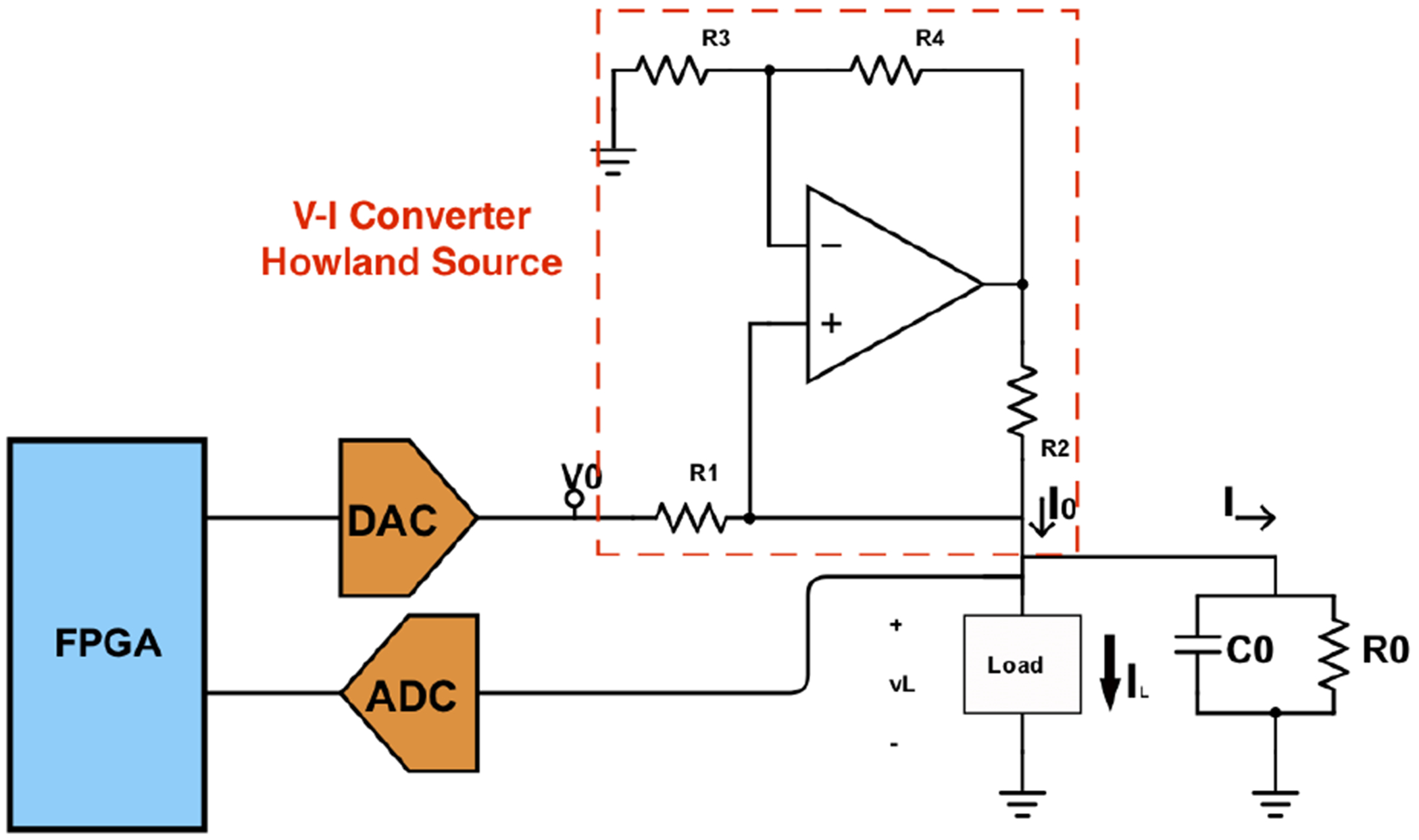
New current source block diagram.
III. Test System
A. Current Source
The prototype implementation used to generate the results for this paper uses the components shown in Table. I. The ADC has 16 bits of precision and operates at 1.2 MSPS and the DAC has 16 bits and operates at 24 MSPS. The Artix 7 FPGA is on a Digilent CMOD-A7-35T module.
TABLE I:
Implemented System Components
| Components | Parts |
|---|---|
| OpAmp | AD8033 |
| Resistors | 0.1% |
| DSP | Artix 7 FPGA |
| DAC | LTC1668, 50 MSPS |
| ADC | AD4002, 2 MSPS |
Although it is not shown in the diagram, a 100 kΩ resistor is placed from the output of the I-V converter to ground. This resistor limits the output impedance of the source but simplifies the calibration process.
B. Coaxial Cable
RG-174 cable, a relatively small diameter (2.79 mm) coaxial cable that is commonly used with EIT systems, is used to evaluate the performance of the current source. Table II shows the datasheet parameters for the cable.
TABLE II:
Cable Parameters
| Parameter | Value |
|---|---|
| Nominal cond. DCR | 97 Ω/1000ft |
| Nominal Capacitance | 30.8 pF/ft |
| Nominal Inducatnce | 0.077 μH/ft |
| Nominal shield DCR | 10.7 Ω/1000ft |
| Characteristic Impedance | 50 Ω |
A 1 m length of cable will be used in the experiments. This length is a small fraction of a wavelength for frequencies up to 1 MHz, meaning that the cable can be accurately modeled using a simple lumped-parameter model as shown in Fig. 3 which shows the cable between the current source and a parallel RC load. The current source is shown with an output impedance represented by the parallel combination of R0 and C0. The current source is connected to the load through the cable that is shown using the simple series RLC lumped model [17] whose parameters can be obtained from Table II. The cable will be terminated with a leaded resistor, which usually will have approximately 0.5 pF of parallel capacitance and is represented with RL, CL. The proposed adaptive current source can compensate for all the fractional current through the parallel source output impedance and any stray impedance to ground, including the cable impedance.
Fig. 3:

Electrical model of a current driven load
C. Shield Driver
Performance will be compared with and without a driven shield. The compensated voltage follower shown in Fig. 4 is used to achieve stability with a large capacitive load [18]. Proper selection of Rcomp and Ccomp significantly improves the driver stability. However, the existence of Rcomp can reduce the output swing. The shield driver was implemented using AD8066 low noise, high-speed opamp. Rcomp and Ccomp are 10 Ω. and 10 pF, respectively.
Fig. 4:
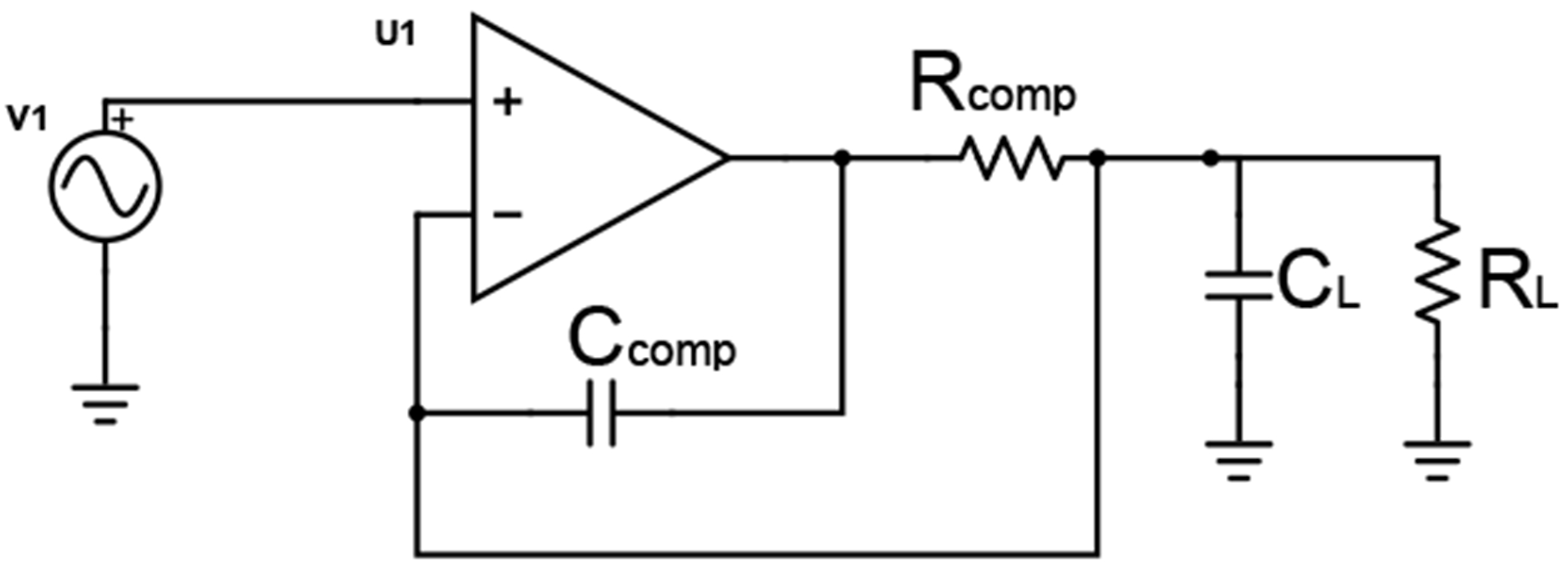
Shield driver schematic
IV. EXPERIMENTS AND RESULTS
For performance evaluation, the current source was first tested with a resistive load connected in 3 ways: directly to the source output, through 1 m of RG-174 cable with the cable shield grounded, and through 1 m of RG-174 cable with the cable shield driven through the driver of Fig. 4.
Fig. 5 shows the measured load resistance and capacitance (modelled as a parallel RC) when delivering current to a 1 kΩ axial leaded resistor with excitation frequency up to 1 MHz and with no cable included. Since the main idea of using active electrodes is to move the electronics to the load side of the cable, the measurements in Fig. 5 can be seen as the performance that would be obtained using an active electrode.
Fig. 5:
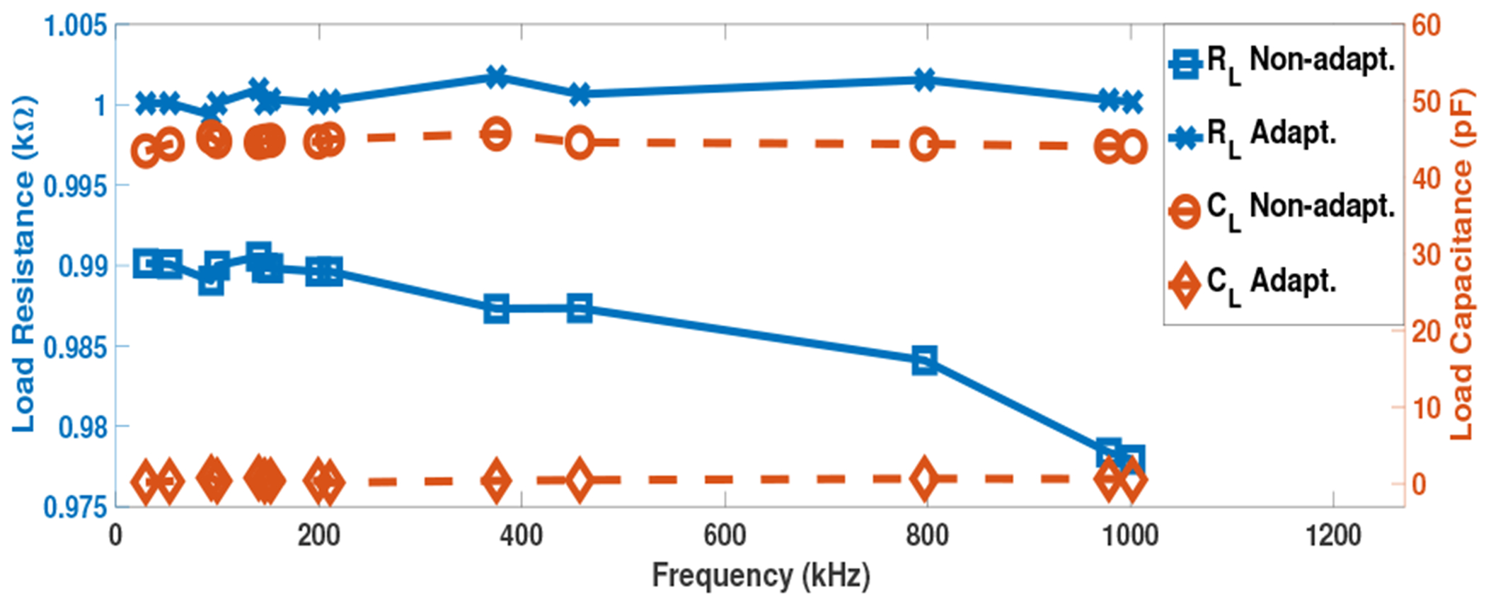
System response across 1 MHz band for 1 kΩ load with no cable
In the “Non-adapt” case, the current source is operating without correction, i.e. the source does not supply additional current to compensate for the output and shunt impedance. For the “adapt” case, this compensating current is supplied. Without correction, the load is approximately 43 pF in parallel with a 990 Ω resistance which drops slightly with increasing frequency. This resistance value is expected due to the 100 kΩ resistor that is at the current source output, i.e. 1 kΩ ‖100 kΩ = 990 Ω.
In the “adapt” case, the measured resistance is near the actual 1 kΩ and the capacitance is below 1 pF. Since an axial leaded resistor has about 0.5 pF of parallel capacitance, the measured capacitance is not expected to become zero.
Fig. 6 shows the measured open circuit capacitance values seen by the current source with and without the cable. Without a cable, the value is approximately 43 pF which is consistent with Fig. 5. The value with the 1 m cable with the shield grounded is approximately 140 pF, a reasonable value given the 100 pF/m capacitance of the cable. The capacitance drops to approximately 50 pF when the shield is driven, which is 7 pF above the 43 pF without the cable, meaning that the use of the shield driver removes over 90% the cable capacitance.
Fig. 6:
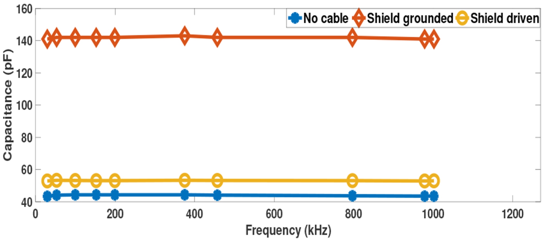
Open circuit capacitance measurements
Fig. 7 shows the experimental results for the current source when driving the 1 kΩ load through the 1 m cable with its shield grounded or driven and with the current source providing compensation. The results without a cable from Fig. 5 are repeated for comparison. The resistance and capacitance measurements for each case are very similar, with neither case with a cable showing a consistent advantage across the frequency range, indicating that the current source can operate equally-well without a shield driver with this 1 m cable. Using a cable does introduce a small increase in the measured load capacitance.
Fig. 7:
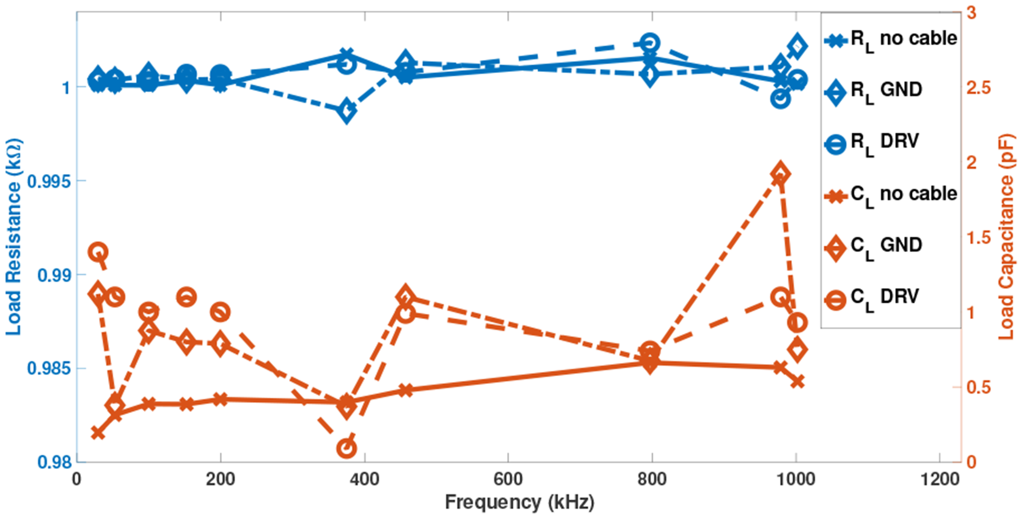
Current source with shield grounded/driven response
Fig. 8 shows results for a complex impedance load that is representative of the impedance presented by a biological load. This Cole-Cole load consists of two parallel circuit branches, one with a 750 Ω resistance in series with 2.2 nF capacitance while the other with a 680 Ω resistance [15]. The figure shows the reactive part of the measured impedance as a function of the real part, for the ideal (computed) case and the measured values without a cable and with a grounded-shield cable. The strong agreement between the cable and no-cable results further demonstrates the ability of the current source to operate effectively with a grounded-shield cable.
Fig. 8:
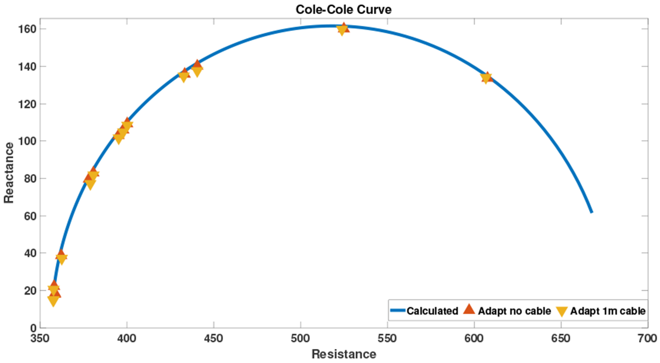
Adaptive Cole-Cole load
V. Discussion and Conclusions
The experimental results using the new current source show a high performance in driving a load connected through a coaxial cable with a nominal capacitance of about 100 pF/m. The overall system performance was nearly the same without a cable and with cable shield grounded and driven, indicating that the source can compensate for the large cable capacitance over a broad frequency range. These results show that it is possible to operate well without shield drivers, resulting in a simpler system with fewer analog components. This approach creates a viable alternative to the active electrode approach where the analog hardware and switches are directly attached to the electrodes and the human body and which may not be convenient for all patients. The grounded shield system showed a similar performance to active electrodes as the effect of the cable capacitance was removed without the need to place active electronics on the electrode itself.
Fig. 2:
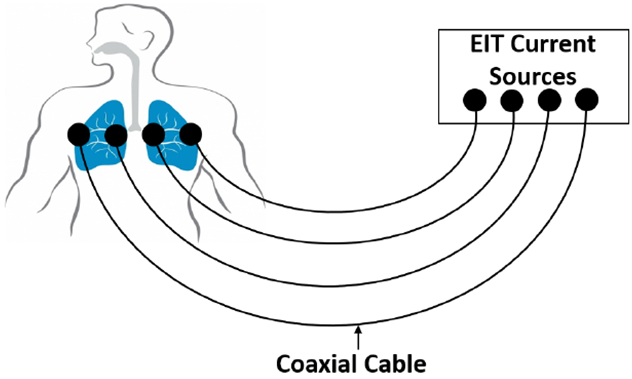
Conventional passive electrodes EIT system.
Acknowledgments
Research reported in this paper was supported by the National Institute of Biomedical Imaging and Bioengineering of the National Institutes of Health under award number 1R01EB026710-01A1. The content is solely the responsibility of the authors and does not necessarily represent the official views of the National Institutes of Health.
References
- [1].Saulnier GJ, Blue RS, Newell JC, Isaacson D, and Edic PM. Electrical impedance tomography. IEEE Signal Processing Magazine, 18(6):31–43, November 2001. [Google Scholar]
- [2].Frerichs I, Hinz J, Herrmann P, Weisser G, Hahn G, Quintel M, and Hellige G. Regional lung perfusion as determined by electrical impedance tomography in comparison with electron beam CT imaging. IEEE Transactions on Medical Imaging, 21(6):646–652, 2002. [DOI] [PMC free article] [PubMed] [Google Scholar]
- [3].Dai T and Adler A. In vivo blood characterization from bioimpedance spectroscopy of blood pooling. IEEE Transactions on Instrumentation and Measurement, 58(11):3831–3838, November 2009. [Google Scholar]
- [4].Metting van Rijn C, Peper A, and Grimbergen C. High quality recording of bioelectric events. part 1. interference reduction, theory and practice. Medical biological engineering computing, 28:389–97, 10 1990. [DOI] [PubMed] [Google Scholar]
- [5].Alnasser E. The stability analysis of a biopotential measurement system equipped with driven-right-leg and shield-driver circuits. IEEE Transactions on Instrumentation and Measurement, 63(7):1731–1738, July 2014. [Google Scholar]
- [6].Spinelli EM and Reverter F. On the stability of shield-driver circuits. IEEE Transactions on Instrumentation and Measurement, 59(2):458–462, February 2010. [Google Scholar]
- [7].Li JH, Joppek C, and Faust U. Fast EIT data acquisition system with active electrodes and its application to cardiac imaging. Physiological Measurement, 17(4A):A25–A32, November 1996. [DOI] [PubMed] [Google Scholar]
- [8].Gaggero P, Adler A, Brunner J, and Seitz P. Electrical impedance tomography system based on active electrodes. Physiological measurement, 33:831–47, 05 2012. [DOI] [PubMed] [Google Scholar]
- [9].de Camargo EDLB de Moura FS Santos TBR. Lima RG Hamilton SJ Muller PA Alsaker M Mellenthin MM Mueller JL. The ACE1 electrical impedance tomography system for thoracic imaging. IEEE Transactions on Instrumentation and Measurement, 68:3137–3150, 2019. [DOI] [PMC free article] [PubMed] [Google Scholar]
- [10].Guermandi M, Cardu R, Franchi Scarselli E, and Guerrieri R. Active electrode IC for EEG and electrical impedance tomography with continuous monitoring of contact impedance. IEEE Transactions on Biomedical Circuits and Systems, 9(1):21–33, February 2015. [DOI] [PubMed] [Google Scholar]
- [11].Saulnier GJ, Abdelwahab A, and Maysha F. DSP-based adaptive current source for EIT applications. In 20th International Conference on Biomedical Applications of Electrical Impedance Tomography (EIT 2019), July 2019. [Google Scholar]
- [12].Holder D. Electrical Impedance Tomography: Methods, History and Applications, volume 32, pages 67–69. 01 2005. [Google Scholar]
- [13].Cook RD, Saulnier GJ, Gisser DG, Goble JC, Newell JC, and Isaacson D. ACT3: a high-speed, high-precision electrical impedance tomograph. IEEE Transactions on Biomedical Engineering, 41(8):713–722, August 1994. [DOI] [PMC free article] [PubMed] [Google Scholar]
- [14].Ross AS, Saulnier GJ, Newell JC, and Isaacson D. Current source design for electrical impedance tomography. Physiological Measurement, 24(2):509–516, April 2003. [DOI] [PubMed] [Google Scholar]
- [15].Santos S, Schlebusch T, and Leonhardt S. Simulation of a current source with a Cole-Cole load for multi-frequency electrical impedance tomography. Conference proceedings : … Annual International Conference of the IEEE Engineering in Medicine and Biology Society. IEEE Engineering in Medicine and Biology Society. Conference, 2013:6445–6448, 07 2013. [DOI] [PubMed] [Google Scholar]
- [16].Saulnier Gary J, Ahmed Abdelwahab, and Omid Rajabi Shishvan. DSP-based current source for electrical impedance tomography. Physiological Measurement, to be published. [DOI] [PMC free article] [PubMed] [Google Scholar]
- [17].Glover JD and Sarma MS. Power System Analysis and Design. Thomson, 2008. [Google Scholar]
- [18].STMicroelectronics. “operational amplifier stability compensation methods for capacitive loading applied to TS 507”. Geneva, Switzerland, 2007. [Google Scholar]


