Abstract
Background:
Mouse models are beneficial to understanding neural networks given a wide array of transgenic mice and cell-selective techniques. However, instrumentation of mice for neurophysiological studies is difficult. Often surgery is prolonged with experimental error arising from non-concurrent and variable implantations.
New method:
We describe a method for the rapid, reproducible and customizable instrumentation of mice. We constructed a headplate that conforms to the mouse skull surface using script-based computer aided design. This headplate was then modified to enable the friction-fit addition of instrumentation prior to surgery and printed at high-resolution resin-based 3D printing. Using this approach, we describe an easily customized headplate with four dural screws for electroencephalography (EEG), electromyogram (EMG) electrodes, a cannula hole and two independent microdrives for local field potential (LFP) microwire electrodes.
Results:
Implantation of the headplate reliably takes less than 40 minutes, enabling a cohort of eight mice to be implanted in one day. Good quality recordings were obtained after surgical recovery and the headplate was stable for at least four weeks. Microwire electrode placement was found to be accurate.
Comparison with existing methods:
While similar approaches with microelectrodes have been used in rats before, and related approaches exist for targeting tetrodes to one brain region, we do not know of similar headplates for mice, nor a strictly source-code and easily reconfigurable approach.
Conclusions:
3D printing and friction-fit pre-assembly of mouse headplates offers a rapid, easily reconfigurable, consistent, and cost-effective way to implant larger numbers of mice in a highly reproducible way, reducing surgical time and mitigating experimental error.
Keywords: EEG recording, 3D printing, mouse surgery, neural networks, chronic recording, headplate
1. Introduction
Mouse models are crucial to understanding certain aspects of neuroscience, being most amenable to cell-targeted technologies. One major drawback in using mice is the relative difficulty and limitations of instrumentation, particularly for neurophysiology. Depending on the complexity of instrumentation, surgery to implant two cortical screws and electromyogram (EMG) electrodes pre-soldered to a plug can take as little as 20 minutes, but it can take three hours or more when additional items, particularly precisely placed microwire electrodes, are added. The size of the mouse skull has been a significant obstacle to these complex implantations, as well as the maximum weight a mouse can maintain on its head, about 4 g (Voigts et al. 2013). These problems become particularly apparent when it is necessary to record from a larger group of mice with low inter-individual variability in implantation, as well as matching the day or time of surgery.
While more sophisticated multielectrode arrays have been developed for mice (Choi et al. 2010; Voigts et al. 2013; Brunetti et al. 2014; Jun et al. 2017; Hultman et al. 2018), there is still a need for simpler implantations with dural screws and microwire electrodes suitable for monitoring large numbers of mice, particularly in studies of sleep-wake (Anaclet et al. 2015; Pedersen et al. 2017) and epilepsy (Hernan et al. 2017; Kadam et al. 2017). Furthermore, recently developed multi-electrode array approaches in mice generally target one brain region and are less suitable for examining sleep-wake or cortical background electroencephalography (EEG) changes. We sought a simpler way of performing recordings of the type used in sleep-wake and epilepsy studies, where a pre-assembled implant could be used to provide screw electrodes for electrocorticography (ECoG), EMG and two microwire electrodes on microdrives to record hippocampal local field potentials (LFP). We aimed to produce a technology that is cheap, light in weight, easily reproducible, as well as easily reconfigured through script-editing, permitting us to record ECoG, LFP and EMG. We modeled a skull-conformal headplate to which several instruments can be added, creating a modular device that can serve multiple purposes, with some resemblance to an approach taken in rats (Headley et al. 2015). This technology was to permit the inexpensive assembly of identical headplates for rapid and stereotyped implantation, including of a whole cohort of mice (e.g. eight mice) in one day, permitting better-controlled experiments.
2. Material and methods
2.1. Design intent
We sought to develop a headplate that was flexible, based on experimental needs, was reliable, resulted in highly stereotyped implantations, had low electrode impedance, and enabled the rapid implantation of a whole cohort of eight mice in one surgical day. The headplate needed to be inexpensive, geometrically accurate, light in weight, and assembled prior to surgery (preferably without soldering). We also sought to use software that enabled rapid revisions or reconfiguration.
2.2. Headplate design
We attempted to create a surface that was conformal to the mouse skull using SolidWorks, Fusion 360, Blender, and found that it was typically time consuming to add and remove headplate features and that Cartesian coordinates could not be easily used. We settled on using OpenSCAD (v 2015.3, www.openscad.org) for these reasons and also because it is a script-based CAD package that could be rapidly modified by changing Boolean variables/logic and by adjusting the Cartesian coordinates of an object’s features. Fifty Cartesian points from the dorsal aspect of the mouse skull, produced from cranial 7.0 Tesla MRI of 40 male and female C57Bl/6J mice aged 12 weeks (Dorr et al. 2008) (https://wiki.mouseimaging.ca/display/MICePub/Mouse+Brain+Atlases), were used to model a skull-conformal polyhedron using OpenSCAD software. To this, a planar top surface was added with the necessary geometry to accommodate the friction-fit assembly of instrumentation. To meet our recording needs, and those common to sleep and epilepsy laboratories, we added four screw holes, two hippocampal microwire electrode holes with microdrive units that have the correct travel for the intended target (e.g. the perforant path overlying the dentate gyrus), a cannula hole, two EMG holes, and eight raised receptacles for an eight-pin plug (Mill-Max connector) (Figure 1, Table 1) (stereolithography (.stl) file available upon request for non-commercial use). The headplate can be modified for different mouse strains, which is essential given substantial intra-stain variability in skull morphology in mice (Wahlsten et al., 1975). This would require adjustment of the cartesian coordinates describing the underside of the headplate in the OpenSCAD script used to generate the headplate model.
Figure 1. Headplate CAD Model.
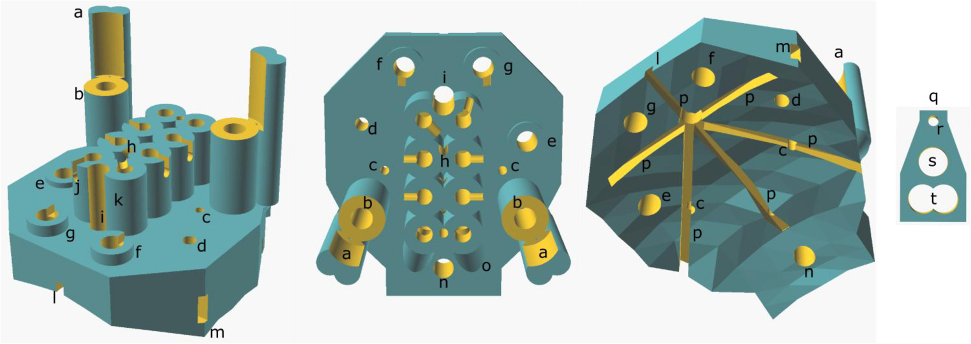
(Left) Diagonal view from above and anterior to the headplate, (middle) from above and (right) from below, showing the skull-conformal polygon base. (a) Microdrive guide post, (b) microdrive screw housing, (c) microwire hole, (d) cannula hole, (e) parietal screw electrode hole, (f) frontal screw hole, (g) ground screw hole, (h) reference wire tunnel entrance, (i) Bregma siting hole, (j) example of wire notch, (k) Mill-Max connector receptacle, (l) anterior glue furrow, (m) lateral glue furrow exit, (n) reference screw hole, (o) EMG wire tunnel outer housing, (p) glue furrows, (q) microdrive platform, (r) microwire hole, (s) microdrive screw hole and (t) the hole for the microdrive guide post.
Table 1.
Size and Location of Holes on Headplate
| Hole | Diameter (mm) | Location (mediolateral, Bregma) |
|---|---|---|
| Screw Hole 1 (Ground) | 0.7 | (1.3, 1.0) |
| Screw Hole 2 (Frontal) | 0.7 | (−1.3, 1.0) |
| Screw Hole 3 (Reference) | 0.7 | (0, − 6.0) |
| Screw Hole 4 (Parietal) | 0.7 | (2.8, − 1.5) |
| Bregma Sighting Hole | 0.5 | (0, 0) |
| Lambda Sighting Hole2 | 0.3 | (0, − 4.21) |
| Hippocampal Microwire Electrode Hole (right) | 0.25 | (2, − 2.53, depth −1.8) |
| Hippocampal Microwire Electrode Hole (left) | 0.25 | (−2, − 2.53, depth −1.8) |
| Cannula Hole (targets amygdala) | 0.45 | (−2.75, − 0.94) |
| EMG Hole (right) | 0.5 | n/a |
| EMG Hole (left) | 0.5 | n/a |
| Mill-Max connector Pin Holes | 0.45 | n/a |
2.3. Headplate printing
A high-resolution Asiga PICO2 printer (PICO2 UV 39 μm, Asiga, Australia) was used to print the headplates (Figure 2). Wall thicknesses and vertical lumens of 250 μm was easily achieved, with the least evidence of light scatter and loss of detail at 50 μm slice thickness. A mUVe 3D printer was also tested (mUVe 3D DLP UltiPro, mUVe3d LLC, Grand Rapids, MI), enabling very high resolution, but daily use, calibration, and obtaining precise feature sizes were more difficult.
Figure 2. Headplate Printing.
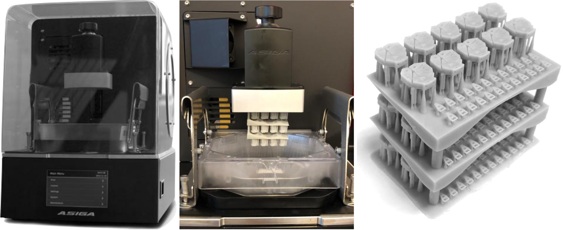
(Left) Asiga PICO2 printer. (Center) Completed print of a three-layered stack of headplates on the build platform of the printer. (Right) The completed print after sonication with isopropyl alcohol, drying and UV curing.
PlasGray (Asiga, Australia, supplier ProtoProducts, TN), a dyed methyl-methacrylate resin with UV photoactivation, provided higher resolution than clear GR1 or GR10 resins (Pro3dure, Germany), in part due to oxygen inhibition of polymerization during final photocuring of the GR materials. Many of the holes on the headplate that were smaller than 0.25 mm diameter were filled in by the resin and were not patent. PlasClear proved to be a better clear resin choice than GR1 or GR10, but it did not reliably provide the high resolution of PlasGray necessary for small lumens in the headplate.
The 3D model was exported as a stereolithography file (.stl) file and opened in Asiga Composer. Supports were generated by default options with manual adjustment to ensure that small holes were not obscured by support material. After addition of support material, the headplate was cloned into a 2 by 5 array and twenty microdrive platforms were then added using the same approach. To increase the number of headplates printed at one time, the ‘multistacking’ function can be used (Figure 2). Four layers can be printed within the build volume allowing for 50 headplates and 100 microdrive platforms to be printed at once. Adherence to the baseplate was best with a 300 μm base plate and 4 burn-in layers, with good detail obtained with a slider speed of 10 mm/s.
After printing, objects were cured in UV light to complete polymerization. Objects were removed from the build plate and rinsed with 100% isopropyl alcohol to remove excess resin. Then they were placed in a beaker filled with clean isopropyl alcohol and sonicated for five minutes (Vevor 1.3L, Shanghai-Sishun, Los Angeles, CA). The objects were rinsed with more isopropyl alcohol and placed back into the sonicator for two more minutes. Some prints were rinsed and sonicated for a further two minutes if resin still occluded some of the microwire electrode holes. The objects were dried with gentle compressed air and then UV cured for nine minutes, flipped at 4.5 minutes for better overall UV exposure (Pico Flash, Asiga, Australia). Note that the propellants added to many canned air canisters interact with the resin and should be avoided. A “workbench block” that would hold headplates during instrumentation and a stereotaxic holder for the headplate were printed. Each were designed on OpenSCAD and printed with the same parameters used for the headplates (.stl files available upon request for non-commercial use). Ten headplates were 3D printed in about 60 minutes. Post-printing procedures took an additional 15 minutes.
2.4. Headplate assembly
Headplate assembly is detailed and takes some practice. Assembly is performed using a stereo-microscope with a bright LED light (SM-3TZZ-144S-B, AmScope, Chino, CA) and a magnetic mat (IF145-167-4, iFixit, San Luis Obispo, CA) that prevents the loss of magnetic parts dropped during assembly. Smaller parts and consumables are listed in Table 3b. To fully assemble a batch of 8 headplates took just over 5 hours.
Headplates were carefully removed from the printed supports and the printed base and placed in an individual well of the workbench block (Figure 3a).
A 1 cm length of non-insulated 0.005” diameter stainless steel wire was fed down the diagonal tunnel found on the anterior seam of the pin holes corresponding to the two microwire electrodes (Figure 1h) so that it reached into the reference hole over the cerebellum (Figure 1n).
The wire is bent upwards into the hole by sticking a slotted 0.6 mm screwdriver from the underside of the headset through the hole.
A M0.8×3 stainless steel pan head screw was selected with forceps (serrated fine tip) and the first 1 mm of the thread of the screw were dipped into premium carbon conductive grease. A very light coating on the screw was ensured. Excess was dabbed off with a Kimwipe.
Using the phillips #000, the screw was screwed into the reference hole until the bottom of the screw was flush with the bottom of the headplate, such that the wire was held in place by the screw but did not extend past the bottom of the screw.
The wire was cut to an appropriate length and the wire was then inserted into the pin hole corresponding with the screw (in our case based on the montage shown in Figure 4). The wire typically extended about 1.5 mm into the pin hole, ensuring that it would stay in place.
A 1 mm hook at the end of a 1 cm length of non-insulated 0.005” diameter wire was made using forceps (#5 forceps). The hook was then placed into one of the remaining three screw electrode holes (Figure 1efg).
Steps 4–6 were repeated for that screw electrode; steps 7 and then 4–6 were applied to the remaining two screw electrodes (Figure 3b).
Two 1.9 cm lengths of the insulated 0.005” diameter wire were then cut. Using a cigarette lighter, the insulation was then burned to remove 2 mm of coating from one end of the wire.
Burn side up, the wires were inserted into the microwire electrode holes (Figure 1c).
Two microdrive platforms were carefully removed from the printed base and slid onto the wires and onto the microdrive towers.
Wires were checked to be all the way down against the bench block. The tops of the microdrive platforms needed to be flush with the top of their respective towers and parallel to the surface of the headplate (Figure 3c). The workbench is turned sideways so that the anterior side of the headplate faces up to avoid the microdrive platforms falling down the microdrive guide-post.
Using a 0.5 mL syringe, the smallest bead of glue on the tip of syringe was placed on the apex of both microdrive platforms at the location of the groove and inserted microwire on both the dorsal and ventral sides of the platform.
Using another 0.5 ml syringe, a bead of Insta-Weld Activator was placed over all superglue to expedite setting. Especial care is taken not to apply glue to the microdrive platform at its contact with the microdrive guide-posts. Glue that runs into the screw hole of the platform, however, is easily removed with the 0.6 mm slotted screwdriver.
The microdrive platform is then removed to test the strength the bond between microelectrode and platform by holding the platform with forceps and gently tugging on either end of the wire with a second pair of forceps. This step is worth practicing to determine the traction tolerated by the platform, which should break before the wire is dislodged.
A M0.8 × 3 stainless steel pan screw was placed and screwed down into the microdrive towers, ensuring that the microdrive platform did not travel during screw insertion (Figure 3h). This was repeated for the other tower.
The wire was bent forward, and forceps (#5 forceps) were used to place the stripped end of the wire as deep as possible into the corresponding pin hole. The wire was bent outwards into the grooves of the pin holes to ensure that they would stay out of the way. This was repeated for the other wire (Figure 3d).
Two EMG wires with pads were cut to 1 cm (including entire EMG pad). Then 1 mm of wire was stripped from the end using a wire stripper (WireFox, Phoenix Contact, Middletown, PA).
EMG leads were then lightly dipped in conductive grease and fed from the posterior side of the headplate up to the EMG wire tunnels into the corresponding pin holes. They were oriented so that the pads lay flat.
Silver conductive epoxy with a 4-hour set rate, in case revision was needed, was prepared by mixing the two chemicals in equal parts, before coating pins of the connector plug by dipping the pins in the mixture then removing the excess with a sharpened wooden handle of a cotton swab applicator. A light coat was ensured and care was taken that none of the pins were bridged together. If there was too much epoxy on the pins, fine forceps (serrated) were also used to remove the excess and immediately washed clean.
The Mill-Max connector was placed into the pin holes, but only depressed to half of the length of pins. It was important at this step to ensure all wires were in their corresponding holes.
The Mill-Max connector was pushed in all the way down while holding the EMG wires in place to ensure that they wouldn’t get pushed back out (Figure 3e).
Using a multimeter (Fluke 115, Everett, WA), every screw and EMG pad connection was verified. One end of the multimeter was placed at the electrode and the other at the pin that corresponded to its connection. Shorts were identified by checking for electrode connections to all non-corresponding pins. If there was no connection where needed, or unwanted shorts, the headplate was disassembled and fixed to ensure proper connection.
Using the multimeter in DC resistance mode, resistance was checked. Screw connections should be under 2.5 Ohms and EMG under 15 Ohms. If the resistance was too high, the headplate was disassembled and fixed to ensure proper connections. The resistance of the microwire electrode wires was not checked but were found to provide good signal. Interelectrode resistance was greater than 40 MOhms (limit of device).
The headplates were sterilized via ethylene gas sterilization at 37˚C in preparation for surgery. Higher temperatures seemed to make the headplate more brittle.
Figure 3. Friction-Fit Assembly of the Headplate.
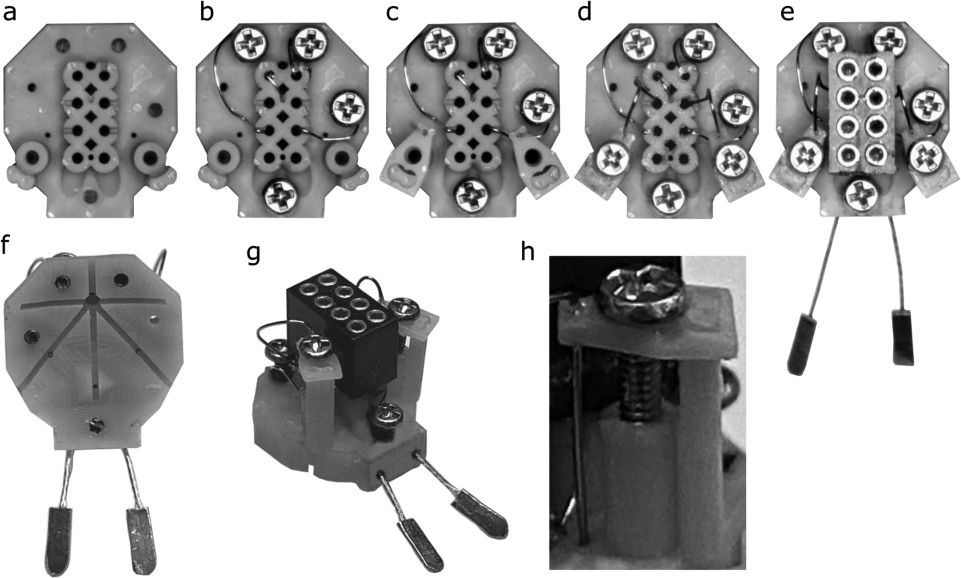
The (a) blank headplate is placed in the 3D printed ‘workbench’ to hold it steady under a stereomicroscope (cut from image for clarity). First, (b) wires are inserted into the screw holes, screw electrodes are placed, and the opposite end of the wires are fed into their corresponding pin holes. (c) Microdrive platforms are added before (d) microwire electrode wires are glued in place onto the platforms, insulated microelectrode wire are inserted into pin holes and platforms are stabilized by screws inserted into microdrive units. Finally, (e) EMG wires are inserted and the Mill-Max connector, with conductive epoxy on the pins, is pushed into the plug receptacle to complete the headplate. The completed headplate shown from (f) below and (g) an oblique view. Note that none of the electrodes or screws protrudes below the bottom surface of the headplate. The assembled microdrive assembly (h) with M0.8×3 machine screw, microdrive platform at the top of the microdrive pole and an electrode glued in place.
Figure 4. Wiring diagram of the headplate as used in our recording.
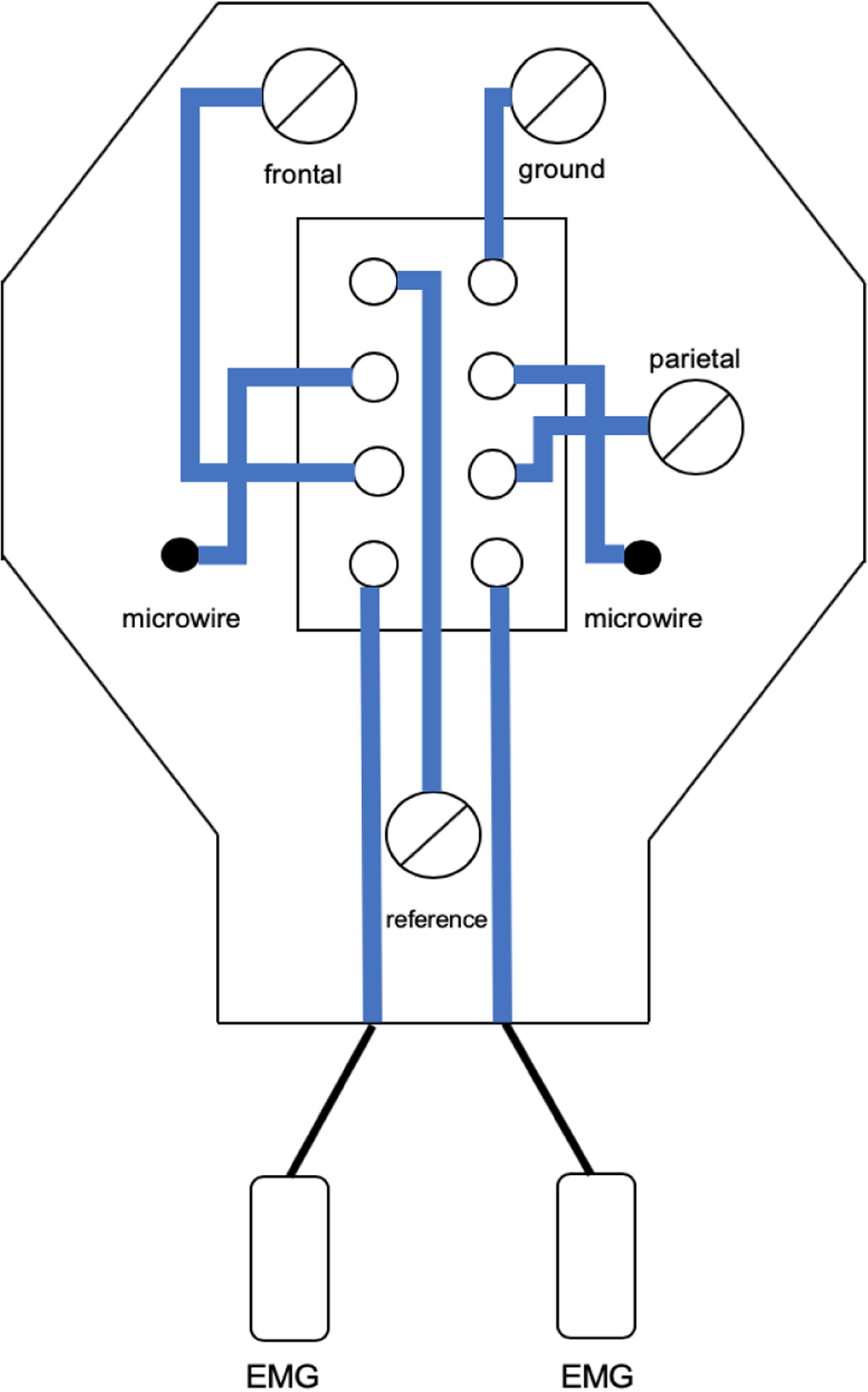
Wiring was designed for a Pinnacle Technologies preamplifier but can be reconfigured.
2.5. Headplate implantation
Mice (12–26 weeks old) with C57bl/6J background and of either sex were used for these studies, in accord with the Emory Institutional Animal Care and Use Committee. While the brain has reached its adult size by 8 weeks (Hammelrath et al., 2016), we chose mice aged 12 weeks given that this is the age of C57 used in the Paxinos and Franklin atlas (2004) and that skull thickening is more complete. Headplates were implanted as follows (see Figure 5), with the assistance of a binocular operating microscope:
Figure 5. Surgical Implantation of Headplates.
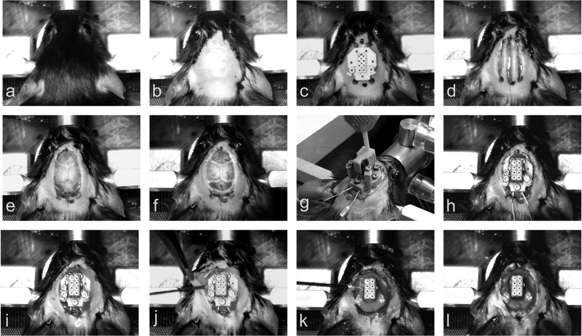
(a) Mouse placed in Cartesian stereotaxic frame. (b) Implantation site cleared of hair and sanitized. (c) Sterile headplate used as a template for the markings of skin to be excised. (d) Three incisions made with the central incision extending ~ 2mm more anterior and more posterior than the lateral incision. (e) Skin removed, EMG tunnels created by blunt dissection between neck muscles and skin, and skull crosshatched. (f) Screw and microwire holes drilled. (g) Placement of headplate onto the skull using the stereotaxic frame. (h) Screw electrodes screwed into the skull. (i) Microwire electrodes screwed to the bottom of travel and EMG wires tucked into subcutaneous tunnels made in step (e). (j) Injection of cyanoacrylic adhesive into Bregma siting hold and of dental cement underneath the skin. (k) Injection of dental cement onto the headplate. (l) Sutures sewn into the skin, if needed, and completed surgery.
Mice were induced with ketamine (100 mg/kg) and xylazine (10 mg/kg) diluted in normal saline and administered by intraperitoneal injection (0.1 mL per 10 g). In addition, 5 mg/kg of meloxicam in saline up to 1 cc was administered by intrascapular subcutaneous injection.
When mice were anesthetized, judged by no righting reflex and ability to be handled, they were placed in a Cartesian stereotaxic frame (Cartesian Instruments now Model 1900, Kopf, Tujunga, CA) on a heated mat with monitoring of blood oxygen concentration, respiratory rate (CO2 sensor in gas outflow line) and body temperature (Somnosuite and Physiosuite, Kent Scientific, Torrington, CT) (Figure 5a).
Anesthesia was maintained with 0 – 1.5% isoflurane delivered in 100% oxygen through a nose-cone connected to a small rodent anesthesia machine (Somnosuite, Kent Scientific, Torrington, CT).
Ophthalmic ointment was applied to the eyes with a cotton swab to keep the eyes moisturized and to prevent depilatory cream from irritating them.
Depilatory cream was applied to the area from the nasal bone to the occiput and extending to the ears, to ensure that the surgical field was free of fur. After leaving this in place for 3 minutes, hair was wiped from the skin with a Kimwipe.
Skin was cleaned with three passes of 70% isopropanol wipes, alternated with an iodine wipe (Figure 5b).
Lidocaine (2% in saline) was instilled subcutaneously using a 0.5 ml syringe at the side of incision and where burr holes were to be placed.
Using a sterile headplate as a template, a sterile surgical marker was used to mark out the region of skin to be excised. Three marks near the top of the headplate and three marks near the bottom of the headplate were made (Figure 5c).
Using a scalpel, three incisions from the top of the headplate area to the bottom of the headplate were made (Figure 5d), such that the lateral incisions were about 2–3 mm shorter than the midline incision.
Using curved surgical scissors, the skin defined by the ends of the two shorter lateral incisions was removed.
The skull was then cleaned with hydrogen peroxide on a sterile saturated cotton swab stick and all periosteal tissue was removed by firm rubbing with the swab.
The back of the scalpel blade was used to score the exposed portion of the skull in a crosshatch pattern (Figure 5e). Care is taken not to apply too much pressure particularly over the sutures where bleeding can then occur.
The planned course of the EMG electrodes over the neck muscles was then blunt dissected, in the tissue plane between skin and muscle. Intramuscular insertion of wires is not necessary in the mouse.
The mouse head was then leveled using the leveling device of the Cartesian frame.
Using the Cartesian stereotaxic frame and its sighting instrument, the location of Bregma on the skull was located, and the digital stereotaxic reader was zeroed (or note can be made of the skull surface measurement on the stereotaxic vertical axis in Vernier-based systems).
Holes were drilled into the skull at locations corresponding to the coordinates of each electrode (Table 1) (Figure 5f). To minimize skull fragments and damage to vessel and brain immediately below the skull, we found a pear-shaped dental burr to be optimal (inverted cone drill bits tend to result in depression fracture of bone chips from the inner table of the skull and spherical burrs are more likely to damage underlying tissue or not create a cylindrical screw hole). Bleeding can occur, particularly over the cerebellar screw hole. Hydrogen peroxide and gelfoam can assist blood coagulation. Suction, through a blunt fill needed, that is not directly applied to the hole can clear the hole enough to examine the cause of bleeding with an operating microscope and diathermy can also be used when bleeding is arising from the skull. Excess gelfoam and blood is removed from the hole before screw insertion to ensure good contact with the cerebellar dural surface.
The headplate was attached to the Cartesian stereotaxic frame using the stereotaxic adaptor that is centered on Bregma (Figure 5g). The headplate was then lowered onto the skull -- the headplate was leveled and aligned with Bregma. Leveling of the skull is critical for contact to be close at all edges of the headplate. This step can also be performed without a stereotaxic holder if care is taken under an operating microscope to align the headplate with screw holes.
With the headplate level on the skull of the mouse, screw electrodes were screwed down into their corresponding holes, starting with the posterior reference screw; lugs on the headplate prevent the screws from descending into the brain, so all screws can be completely lowered. The stereotaxic adaptor was then removed from the headplate (Figure 5h).
The EMG electrodes were tucked underneath the skin in the blunt dissected tunnels. Care is taken to ensure that the EMG paddles are not sitting up from the muscle (this can result in erosion through the overlying skin).
Next, the microwire electrode platforms were screwed down (Figure 5i).
Cyanoacrylic adhesive was dipped into a 0.5 ml insulin syringe (with the plunger out), the plunger replaced, air bubbles removed, and glue gently injected into the Bregma siting hole (Figure 1i) to run into the glue furrows (Figure 1p) and on to the skull under the headplate. Typically, about 20 μl of glue is needed, injected such that glue can be seen in the glue furrows at the side of the headplate.
Dental cement, mixed to slightly more than watery viscosity, is drawn into a syringe with a 20-gauge blunt fill needle. The skin was retracted to ensure that the dental cement would run under the skin (Figure 5j) and that skin would not regrow underneath the headplate – the major reason for headplate loss is pressure created by skin healing under the headplate. Enough dental cement was placed, in layers, to cover the headplate fully up until the top of the Mill-Max connector – it was ensured that no dental cement covered the top of the connector. The surrounding skin was pulled away from the dental cement (Figure 5k).
Using silk 5–0 reverse cutting sutures, one suture was placed both at the back and at the front of the headplate to oppose the skin surrounding the dental cement and affix it with cyanoacrylic adhesive, again ensuring that skin will not grow under the headplate (Figure 5l).
Given that the headplate is screwed in place, then mouse can be immediately carefully removed to a heated pad for recovery. When the mouse is ambulatory, they are placed in our recording chambers. The use of a home cage with a wire top should be avoided for the first day to allow curing of dental cement, but we have found the headplate to be stable with a wire-top cage after that time.
2.6. Recovery
Mice recover for 4 full days before connection to the tether and commutator, permitting 72 hours of habituation before recording commences at 1 week after surgery. Mice were singly housed after surgery in recording barrels (130 oz. clear acrylic container, Oggi Corporation, Anaheim, CA) with drill holes for a drink bottle (Choco Nose H125, Haywood, CA, one steel ball removed, affixed with 3d-printed adaptor, https://3dprint.nih.gov/discover/3DPX-011069) and, in the center of the lid, for the commutator (plate 3D filament printed to hold Pinnacle Commutator and a 1 megapixel day/night dome USP security camera, ELP, Shenzhen, China, https://3dprint.nih.gov/discover/3DPX-011070).
2.7. Mouse Recording
The headplate was designed to be easily modified for use with any recording system, but the montage shown below is designed for commercially available components. We created the montage to fit with a Pinnacle preamplifier (8406-SE31M, 100x gain), commutator (model 8408) and analogue adapter (8442-PWR), with synchronized video-EEG/EMG recorded using a Cambridge Electronic Design Power 1401 A-D converter with a 16-channel top-box with an additional 10x gain, using Spike2 (Version 9.04b, Cambridge Electronic Design, Cambridge, UK). Data was sampled at 2 kS/s without online filtering. Recordings were automatically both saved and restarted every 12 hours with the Spike2 automation feature. Up to four synchronized video streams can be acquired with Spike2, so four mice were recorded per computer. Data was filtered with typical filter settings (EMG high-pass 5 Hz 2nd order Butterworth and LFP/EEG band-pass 1–70 Hz 4th order Butterworth, digital filters, Spike2 version 9.04b) with no line-frequency (60 Hz) notch filter.
2.8. Re-Validation of Use
A cohort of 8 mice (aged 26 weeks) were implanted to give a specific real-world description of headplate performance with the final design, taking an average of 38 minutes per mouse with a surgeon and an assistant to prepare mice. This validation was performed with an inverted cone drill and we have since found that use of the pear-shaped drill tip speeds surgery further given that there is no need to remove bone chips and the need to control bleeding is lessened (see also surgical step 16 above). Another mouse with spontaneous seizures after intra-amygdala kainic acid injection (Almeida Silva et al. 2016) was also recorded to demonstrate use in this setting and to show the independence of hippocampal microwires.
An additional mouse was injected with kainic acid (0.3 μg in 200 nl) over 5 minutes, by ~ 30 μm tip glass capillary (Nanoject III, Drummond Scientific, Broomall, PA) under isoflurane anesthesia before headplate placement. Status epilepticus, typically appearing after isoflurane cessation, was terminated 40 minutes after seizure onset with diazepam (5 mg/kg i.p.). Recording commenced at 72 hours and continued until post-operative day 21.
2.9. Histology
After recording, mice were deep anesthetized with intraperitoneal pentobarbital (150 mg/kg) then transcardially perfused with saline (~ 30 ml) and 10% formalin in neutral PBS (~ 100 ml). After 4–6 hours of post-fixation, the brain was then placed in 30% sucrose in PBS for at least 48 hours before sectioning a 1:3 series at 35 μm. Sections were mounted and then Nissl-stained before review under a microscope to localize microelectrode placement.
3. Results
3.1. The overall design intent was satisfied
Overall, the design intent was achieved. The components and consumables for the headplate cost about US $30 per headplate. The headplate is very light, even with dental cement, weighing about 0.7 g. Overall, headplates rarely needed repair after impedance testing and, if they were fully tested during assembly, did not fail at the time of implantation. Given the lugs to prevent excess screw travel, brain injury was minimal. Rapid implantation was also achieved. We were able to place headsets in less than 40 minutes from the time of induction to placing the mouse on the recovery mat. We think that this time could be further shortened, perhaps making isoflurane maintenance anesthesia needless. The use of isoflurane also enabled us to prolong surgery for the stereotaxic microinjection of vector prior to headplate placement. Recording quality was excellent.
3.2. Reliable recording were obtained
Good quality recordings were stable over at least four weeks of continuous recording (after one week of recovery for a total of five weeks). We expect that much longer times will be achievable: Headplates did not come off prior to euthanasia for perfusion and one mouse was recorded for 16 weeks. Characteristic field potential recordings, electrocorticography and EMG recordings were obtained. Up to four mice were recorded with synchronized video, all with excellent signal on each channel. Given good quality signals, sleep-wake staging was clear (see Figures 6 and 7).
Figure 6. Recording from the headplate.
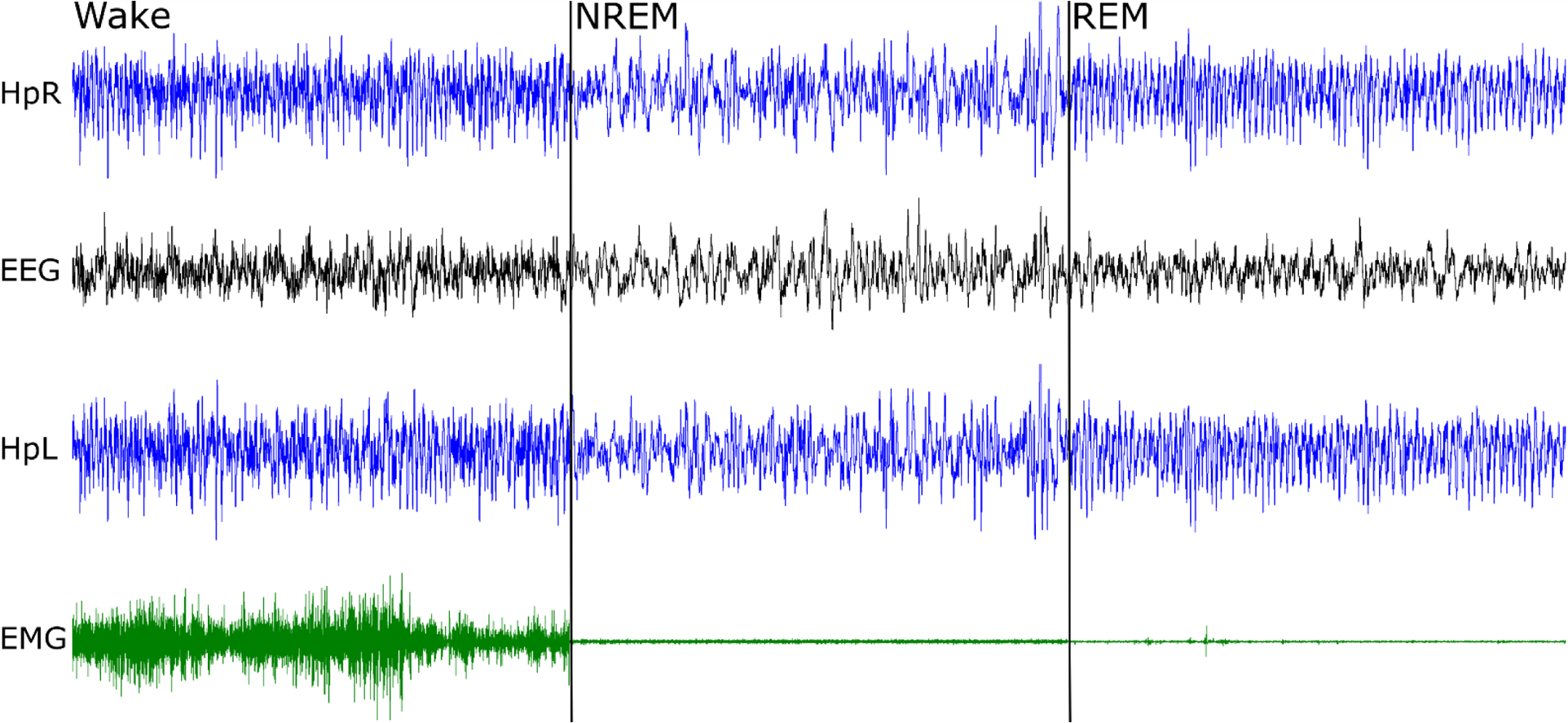
Right hippocampus (HpR), electroencephalogram (EEG), left hippocampus (HpL) and electromyogram from the neck muscle (EMG) were recorded. The total duration of the panel is 30 seconds, with 10 second examples of wake, non-REM sleep and REM sleep. Note sequential fall of EMG amplitude and prominent theta activity (here ~9 Hz), best seen in hippocampal electrodes during REM sleep.
Figure 7. Example of four simultaneously recorded mice (M1–4).
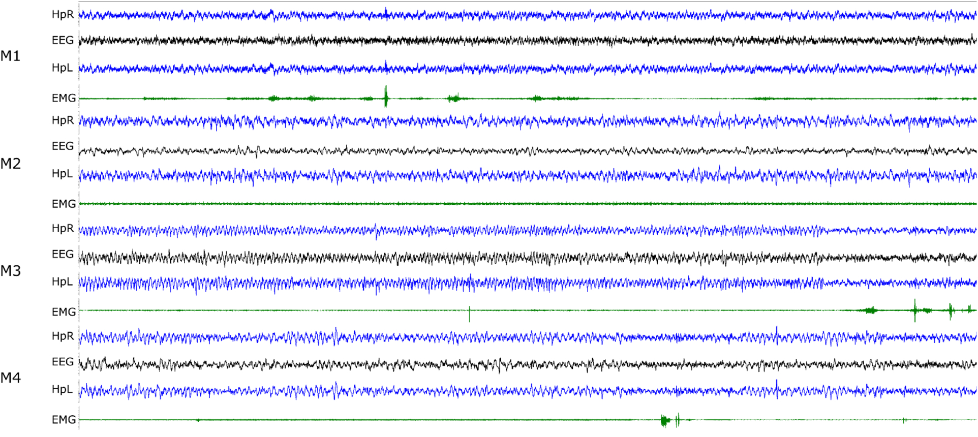
Right hippocampal (HpR), left hippocampal (HpL), ECoG (EEG) and neck EMG traces are shown. The duration of the segment is 30 seconds and the typical range for the LFP/EEG traces is ± 10–20 μV and EMG is ± 200–500 μV. Mouse M1 is awake; M2 and M4 are in NREM sleep with brief arousals for M4 at about 20 and 27 seconds; mouse M3 is in REM sleep for the first 25 seconds with an arousal following.
3.3. Headplate use in the intra-amygdala kainic acid model of epilepsy
The headplate was designed for chronic use and is suited to recording in sleep-wake and spontaneous seizure models. We show an example (Figure 8, Figure 9 for electrode tip location) of headplate use with the intra-amygdala kainic acid model to illustrate the electrophysiological independence of hippocampal microwires. Discharges appear interictally ipsilateral to the kainic acid injection (left) without propagation or volume conduction to the contralateral hippocampus (right).
Figure 8. A spontaneous seizure in the mouse intra-amygdala kainic acid model of medial temporal lobe epilepsy.
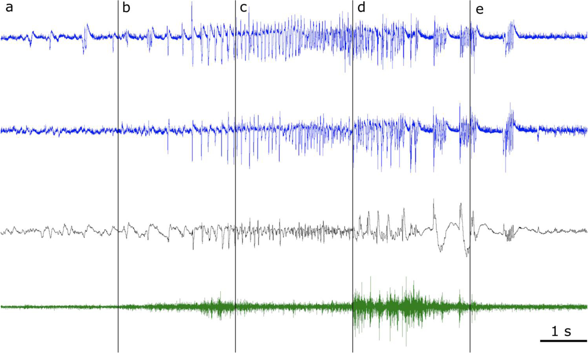
Pre-ictal baseline (a) with epileptiform discharges of the left hippocampus (blue, top) that are not propagated or volume conducted to the right hippocampus (blue, second from top) and have low amplitude or no correlate in the cerebral cortex (black, third row from the top), demonstrating that the microwires record local activity. Seizure onset with periodic hippocampal spiking (b), evolution (c), progression to the clonic phase (d) with prominent cortical discharges and (e) seizure cessation. Neck muscle EMG is shown in the bottom trace (green).
Figure 9. Anatomical drawing showing the location of microwire electrode tips.
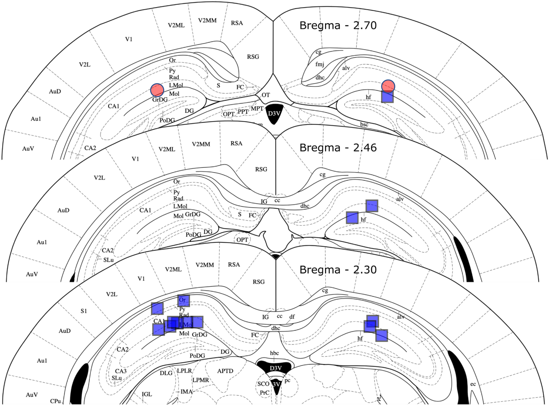
The location of the tip of the electrode is shown for a cohort of eight mice (blue squares) and one mouse with spontaneous seizures after intra-amygdala kainic acid injection (red circles). In two mice, one right-sided electrode failed to deploy. In all cases, the electrode tip was in the hippocampal formation and near the perforant path target above the dorsal blade and of the dentate gyrus, in most cases the electrode was above the hippocampal fissure as intended. See the text for accuracy of electrode tip location. Figure adapted from Paxinos and Franklin, 2004).
3.4. Accuracy of microelectrode placement
Histological examination of Nissl-stained 60 μm sections was performed to determine microelectrode tip location in all mice (see Figure 9). In our re-validation cohort of eight mice, 14 of 16 microelectrodes deployed (both in six mice, one in two mice). The electrode tip target was Bregma −2.53, ± 2 mediolateral and 1.8 mm dorsoventral. Left-sided electrodes mean stereotaxic coordinate was Bregma −2.30 (± 0 S.E), - 1.79 (± 0.08) lateral and 1.62 (± 0.06) mm below the skulls surface; right-sided mean tip locations were Bregma −2.42 (± 0.06), - 1.74 (± 0.06) lateral and 1.82 (± 0.05) mm ventral. Mean 3-dimensional error was thus 423 (± 0.06) and 360 (± 0.03) μm for left and right, respectively, amounting to 2–3 electrode tip diameters. The variance for error in each dimension was low, suggesting that moving the electrode hole and depth by modifying the headplate would correct much of this error. However, all electrodes provided a signal of large amplitude and consistent with hippocampal field potential with most in the perforant path. The two electrodes that failed to deploy were due to omission of testing of the strength of this bond prior to implantation, as described in assembly step 15 above.
4. Discussion
Overall, this approach resulted in several significant time efficiencies and moved intraoperative time to time for headplate assembly. This should result in in better tolerated surgery and enable matching a small cohort of eight mice to one surgical day. This work adds to the growing body of 3D printed laboratory equipment and is intended for wider use in the neuroscience community. We are presently working on a newly designed matching preamplifier and data analysis pipeline for chronic recording for sleep-wake and epilepsy research that we also plan to make generally available. The strong theta activity obtained from hippocampal electrodes will make this headplate suited to automatic sleep scoring (Gao et al. 2016), dependent on high theta differentiation in each sleep-wake state, that probably has higher accuracy using hippocampal LFP than with cortical EEG (Costa-Miserachs et al. 2003).
Three-dimensional printing techniques are increasingly useful in biomedical research, printers are now affordable enough to provide rapid in-house prototyping, speeding development by comparison to commercial printing. Three-dimension printing has been applied to printing of electrode, optical fiber and other neuroscience instrumentation for rodents. There is no device equivalent to our headplate in design intent or function for mice, with most devices aimed at mini-microscopes, single unit or single locus microwire or silicon probe recording (Voigts et al. 2013; Brunetti et al. 2014; Chung et al. 2017; Liang et al. 2017; Delcasso et al. 2018; Aharoni et al. 2019). One exception for rats permits distributed recording of multiple brain regions in the rat (Headley et al. 2015). Our headplate was intended to be used for chronic recording in mice for sleep-wake, hippocampal EEG and seizure analysis, where the conventional approach is implantation of screws and electrodes separately resulting in longer surgical times and reducing the number of mice that can be implanted in one surgical session. Another simpler and commercially available system that includes a template with screw holes does not include microwires.
5. Conclusion
This approach provides for complex implantations in the limited space available on the head of the mice, with more instrumentation than otherwise available for hardware for EEG recording. This approach permits the inexpensive, rapid, and highly reproducible implantation of mice for work that requires large cohorts of mice. Given that we have used a script-based CAD, the headplate can be adapted to other purposes. Other strains of mice, as well as the incorporation of changes to the montage or addition of other instruments such as cannulae, additional microelectrodes and optical fibers can be accommodated (please contact the authors).
Table 2.
Materials Used.
| a. Printing | ||||
|---|---|---|---|---|
| Item | Cat. # | Quantity | Company | Location |
| 500 mL plastic cup containers | 1 | Lock and Lock | South Korea | |
| Isopropyl alcohol | ES602 | 1 gal | Azer Scientific | Morgantown, PA |
| Methyl methacrylate resin | Plasgray V2.0 | 1 liter | Asiga | Sydney, Australia |
| b. Assembly (quantities per headplate) | ||||
| Item Name | Cat. # | Quantity | Company | Location |
| Stainless Steel Wire (uninsulated) | 793800 | 6 cm | A-M Systems | Sequim, WA |
| Stainless Steel Wire (insulated) | 005SW-30S WIRE 37365 S-S 0.005in | 3 cm | Plastics One | Roanoke, VA |
| Screwdriver, slotted 0.6 mm | S0501B | 1 | Armway | |
| Screwdriver, Phillips #000 | 51-1775 | 1 | Moody Tools from Amazon | Seattle, WA |
| Dumont Forceps #5 | EAN 0752423634583 | 1 | Vetmed USA, from Amazon | Seattle, WA |
| McIndoe Style serrated fine forceps | Splinter forceps, fine point, 4.5 inch, stainless, serrated | 1 | Tamsco, from Amazon | Seattle, WA |
| Screws | M08-30-M-SS-P | 6 | US Microscrew, Amazon | Seattle, WA |
| Carbon grease | #8481-1 | As needed | MG Chemicals | Canada |
| Lint-Free tissues | Kimwipes, Kimtech | As needed | Kimberly-Clark | Irving, TX |
| Lighter | Lighter | 1 | BIC | Shelton, CT |
| Cyanoacrylic adhesive | Superglue | As needed | Super Glue Corp. | Canada |
| 0.5 mL 28G Insulin syringe | 8881500014 | 2 | Covidien | Mansfield, MA |
| Cyanoacrylic activator | Insta-Weld Activator | As needed | Polyvance | Rainsville, AL |
| Silver conductive epoxy | #8331-14G | As needed | MG Chemicals | Canada |
| Cotton swab applicator | 25-806 | 1 | Puritan | Guilford, ME |
| EMG Pads on wire | E363-76-NS-SPC Elect 0.125” PAD0-socket 0.010” wire | 2 | Plastics One | Roanoke, VA |
| 8 pin Mill-Max connector | 853-43-008-10-001000 | 1 | MillMax | Oyster Bay, NY |
| Wire Stripper | WireFox | 1 | Phoenix Contact | Middletown, PA |
| c. Surgery | ||||
| Item | Cat. # | Quantity | Company | Location |
| Ketamine | NDC 50989-161-06 | 100 mg/kg | Vedco | Saint Joseph, MO |
| Xylazine | NDC 50989-149-11 | 10 mg/kg | Vedco | Saint Joseph, MO |
| Meloxicam | NDC 0010-6013-01 | 5 mg/kg | Boehringer Ingelheim | Germany |
| 0.9% NaCl Solution | 5257 | 1 cc | CareFusion | San Diego, CA |
| 1 mL Sub-Q Syringe | DG518206 5000029607 | 3 | Becton, Dickinson, and Company | Franklin Lakes, NJ |
| Isoflurane | NDC 66794-017-25 | As needed | Piramal | India |
| Vaseline | As needed | Unilever | United Kingdom | |
| Puralube VET ointment | As needed | Dechra | United Kingdom | |
| Nair | As needed | Church and Dwight | United Kingdom | |
| Lint-Free tissues | Kimwipes, Kimtech | As needed | Kimberly-Clark | Irving, TX |
| 70% isopropanol wipes | Webcol 2 ply, large | 3 | Covidien | Mansfield, MA |
| Povidone-Iodine USP medium prep pad | 3 | Medline | Northfield, IL | |
| Viscot Skin Marker Fine Tip XL | 1 | Viscot Medical | East Hanover, NJ | |
| Scalpel blade #15 | 0297 | 1 | Integra LifeSciences | |
| Scalpel Handle No. 3 | 10604 | 1 | Defender from Amazon | Seattle, WA |
| Curved surgical scissors | 6627010 | 1 | DDP from Amazon | Seattle, WA |
| Drill bit, 0.6 mm pear | FG 329 | 1 | NeoBurr from Microcopy | Kennesaw, GA |
| Cotton swab stick | 25–806 10WC | As needed | Puritan | Guilford, ME |
| Gelfoam | As needed | Phamacia and Upjohn | Kalamazoo, MI | |
| Screwdriver, Phillips #000 | 51–1775 | 1 | Moody Tools from Amazon | Seattle, WA |
| Cyanoacrylic adhesive | Vetbond | As needed | 3M from Amazon | Seattle, WA |
| 0.5 mL insulin syringe | 8881500014 | 1 | Covidien | Ireland |
| Clear Dental cement | 1330 | As needed | Lang Dental | Wheeling, IL |
| 20-gauge blunt fill needle | 305183 | 1 | Becton, Dickinson, and Company | Franklin Lakes, NJ |
| Needle Holder (Olsen Hegar) | AS-042 | 1 | ARTMAN, from Amazon | Seattle, WA |
| PERMA-HAND silk 18” 5–0 reverse cutting sutures | 1 | Ethicon Medical | Cornelia, GA | |
HIGHLIGHTS.
High resolution 3D printing can be used to create mouse headplates for neurophysiology
3D printed headplates allow for consistent and rapid surgical implantation
Using a script-based CAD, headplates can easily be reconfigured to suit the research question
Acknowledgements
We thank Dr. Claire-Anne Gutekunst, Emory Neurosurgery, and Drs. Wenyi Wang, Asheebo Rojas and Ray Dingledine, Emory Pharmacology, for feedback about use of the headplate, including earlier iterations of the design.
Funding: Research reported in this publication was supported by the National Institute of Neurological Disorders and Stroke of the National Institutes of Health under Award Number K08NS105929 (to NPP). The content is solely the responsibility of the authors and does not necessarily represent the official views of the National Institutes of Health; Laboratory Support was also provided by the Woodruff Foundation (NPP); KJZ was supported by an Alfred H. Gibeling Family Research Fund Award and a Georgia Institute of Technology President’s Undergraduate Research Aware (PURA, 2018).
Abbreviations:
- EEG
Electroencephalogram
- ECoG
Electrocorticogram
- EMG
Electromyogram
- CAD
Computer-aided design
- LFP
Local field potential
- MRI
Magnetic resonance imaging
- NREM
Non-rapid eye movement (sleep)
- REM
Rapid-eye movement (sleep)
- UV
Ultraviolet
Footnotes
Conflicts of interest: Emory University has a pending patent for this headplate, but .stl files and headplate redesign instructions are available for non-commercial academic use (please contact npeders@emory.edu). The authors have no other conflicts of interest.
References
- Aharoni D, Khakh BS, Silva AJ, Golshani P. All the light that we can see: a new era in miniaturized microscopy Nature Methods. Nature Publishing Group; 2019. January;16(1):11–3. [DOI] [PMC free article] [PubMed] [Google Scholar]
- Almeida Silva LF, Engel T, Reschke CR, Conroy RM, Langa E, Henshall DC. Distinct behavioral and epileptic phenotype differences in 129/P mice compared to C57BL/6 mice subject to intraamygdala kainic acid-induced status epilepticus. Epilepsy Behav. 2016. November;64(Pt A):186–94. [DOI] [PubMed] [Google Scholar]
- Anaclet C, Pedersen NP, Ferrari LL, Venner A, Bass CE, Arrigoni E, et al. Basal forebrain control of wakefulness and cortical rhythms. Nature Communications. 2015;6:8744. [DOI] [PMC free article] [PubMed] [Google Scholar]
- Brunetti PM, Wimmer RD, Liang L, Siegle JH, Voigts J, Wilson M, et al. Design and Fabrication of Ultralight Weight, Adjustable Multi-electrode Probes for Electrophysiological Recordings in Mice. JoVE. 2014;(91):1–10. [DOI] [PMC free article] [PubMed] [Google Scholar]
- Choi JH, Koch KP, Poppendieck W, Lee M, Shin H-S. High resolution electroencephalography in freely moving mice. Journal of Neurophysiology. 2010. September;104(3):1825–34. [DOI] [PubMed] [Google Scholar]
- Chung J, Sharif F, Jung D, Kim S, Royer S. Micro-drive and headgear for chronic implant and recovery of optoelectronic probes Sci Rep. Springer US; 2017. June 5;7(1):73–10. [DOI] [PMC free article] [PubMed] [Google Scholar]
- Costa-Miserachs D, Portell-Cortés I, Torras-Garcia M, Morgado-Bernal I. Automated sleep staging in rat with a standard spreadsheet. J Neurosci Methods. 2003. November 30;130(1):93–101. [DOI] [PubMed] [Google Scholar]
- Delcasso S, Denagamage S, Britton Z, Graybiel AM. HOPE: Hybrid-Drive Combining Optogenetics, Pharmacology and Electrophysiology. Front Neural Circuits. Frontiers; 2018;12:41. [DOI] [PMC free article] [PubMed] [Google Scholar]
- Dorr AE, Lerch JP, Spring S, Kabani N, Henkelman RM. High resolution three-dimensional brain atlas using an average magnetic resonance image of 40 adult C57Bl/6J mice. NeuroImage. 2008. August 1;42(1):60–9. [DOI] [PubMed] [Google Scholar]
- Gao V, Turek F, Vitaterna M. Multiple classifier systems for automatic sleep scoring in mice. J Neurosci Methods. 2016. May 1;264:33–9. [DOI] [PMC free article] [PubMed] [Google Scholar]
- Headley DB, DeLucca MV, Haufler D, Paré D. Incorporating 3D-printing technology in the design of head-caps and electrode drives for recording neurons in multiple brain regions. Journal of Neurophysiology. 2015. April 21;113(7):2721–32. [DOI] [PMC free article] [PubMed] [Google Scholar]
- Hernan AE, Schevon CA, Worrell GA, Galanopoulou AS, Kahane P, de Curtis M, et al. Methodological standards and functional correlates of depth in vivo electrophysiological recordings in control rodents A TASK1-WG3 report of the AES/ILAE Translational Task Force of the ILAE. French JA, Galanopoulou AS, O’Brien TJ, Simonato M, editors. Epilepsia; 2017. November 6;58(Suppl. 4):28–39. [DOI] [PMC free article] [PubMed] [Google Scholar]
- Hultman R, Ulrich K, Sachs BD, Blount C, Carlson DE, Ndubuizu N, et al. Brain-wide Electrical Spatiotemporal Dynamics Encode Depression Vulnerability. Cell. 2018. March 22;173(1):166–180.e14. [DOI] [PMC free article] [PubMed] [Google Scholar]
- Jun JJ, Steinmetz NA, Siegle JH, Denman DJ, Bauza M, Barbarits B, et al. Fully integrated silicon probes for high-density recording of neural activity Nature. Nature Publishing Group; 2017. November 8;551(7679):232–6. [DOI] [PMC free article] [PubMed] [Google Scholar]
- Kadam SD, D’Ambrosio R, Duveau V, Roucard C, Garcia-Cairasco N, Ikeda A, et al. Methodological standards and interpretation of video-electroencephalography in adult control rodents A TASK1-WG1 report of the AES/ILAE Translational Task Force of the ILAE. French JA, Galanopoulou AS, O’Brien TJ, Simonato M, editors. Epilepsia; 3rd ed 2017. November 6;58(Suppl. 4):10–27. [DOI] [PMC free article] [PubMed] [Google Scholar]
- Liang L, Oline SN, Kirk JC, Schmitt LI, Komorowski RW, Remondes M, et al. Scalable, Lightweight, Integrated and Quick-to-Assemble (SLIQ) Hyperdrives for Functional Circuit Dissection Front Neural Circuits. Frontiers; 2017;11(e51675):8. [DOI] [PMC free article] [PubMed] [Google Scholar]
- Pedersen NP, Ferrari L, Venner A, Wang JL, Abbott SBG, Vujovic N, et al. Supramammillary glutamate neurons are a key node of the arousal system. Nature Communications. 2017. November 10;8(1):1405. [DOI] [PMC free article] [PubMed] [Google Scholar]
- Voigts J, Siegle JH, Pritchett DL, Moore CI. The flexDrive: an ultra-light implant for optical control and highly parallel chronic recording of neuronal ensembles in freely moving mice. Front Syst Neurosci. 2013;7:8. [DOI] [PMC free article] [PubMed] [Google Scholar]


