

Abstract
Genetically engineered mouse model(GEMM) that develops pancreatic ductal adenocarcinoma(PDAC) offers an experimental system to advance our understanding of radiotherapy(RT) for pancreatic cancer. Cone beam CT(CBCT)-guided small animal radiation research platform(SARRP) has been developed to mimic the RT used for human. However, we recognized that CBCT is inadequate to localize the PDAC growing in low image contrast environment. We innovated bioluminescence tomography(BLT) to guide SARRP irradiation for in vivo PDAC. Before working on the complex PDAC-GEMM, we first validated our BLT target localization using subcutaneous and orthotopic pancreatic tumor models. Our BLT process involves the animal transport between the BLT system and SARRP. We inserted a titanium wire into the orthotopic tumor as the fiducial marker to track the tumor location and to validate the BLT reconstruction accuracy. Our data shows that with careful animal handling, minimum disturbance for target position was introduced during our BLT imaging procedure(<0.5mm). However, from longitudinal 2D bioluminescence image(BLI) study, the day-to-day location variation for an abdominal tumor can be significant. We also showed that the 2D BLI in single projection setting cannot accurately capture the abdominal tumor location. It renders that 3D BLT with multiple-projection is needed to quantify the tumor volume and location for precise radiation research. Our initial results show the BLT can retrieve the location at 2mm accuracy for both tumor models, and the tumor volume can be delineated within 25% accuracy. The study for the subcutaneous and orthotopic models will provide us valuable knowledge for BLT-guided PDAC-GEMM radiation research.
Keywords: pancreatic cancer, small animal irradiator, bioluminescence tomography, image-guided radiation therapy
1. INTRODUCTION
Pancreatic cancer is the 7th leading cause of cancer death worldwide1. Current treatment approaches are ultimately ineffective, and novel treatment strategies are desperately needed. The role of radiation therapy (RT) for pancreatic cancer has traditionally been assigned to palliation. Recently, the new approach of radio-immunotherapy where high dose stereotactic body radiation therapy is used to elicit systemic treatment via immunotherapy agents has stimulated tremendous excitement and inspired several clinical trials to treat pancreatic cancer2–4.
The possibility of developing radio-immunotherapy as a systemic treatment has cast the use of radiation into a pivotal role in the management of pancreatic cancer. Given the early clinical studies, there is a compelling need to establish a clinically relevant experimental system to further advance our understanding of the role of RT. Most promising is the use of genetically engineered mouse models (GEMMs) that spontaneously develop pancreatic ductal adenocarcinoma (PDAC) along with a competent and fully intact immune system. The generation of a pancreas specific autochthonous GEMM could provide an innovative resource to understand potential treatment option for pancreatic cancer.
As for the important pre-clinical research to study treatment response of this PDAC-GEMM, the research setting needs to mimic the RT used for human. Such advanced technology is now available in the form of the small animal radiation research platform (SARRP) pioneered at our institution5, 6. The SARRP is equipped with CBCT to guide radiosurgery-like delivery with an accuracy of 0.2 mm using beams as small as 1 mm in diameter7. While CBCT provides the valuable irradiation guidance8–11, it is inadequate for localizing the PDAC growing in a low imaging contrast tissue environment. Because of its strong soft tissue contrast, non-ionizing features and free of background noise, bioluminescence imaging (BLI) has been extensively applied in pre-clinical oncology studies12–14, and it provides an attractive solution to localize soft tissue target. However, because optical transport from an internal light source is highly susceptible to the irregular torso and tissue optical properties, the two-dimension (2D) BLI from object surface cannot be used reliably to infer the internal source location for radiation guidance15, 16. With the employment of a forward model of light propagation through tissue to the skin surface, in conjunction with an optimization algorithm, three-dimension (3D) bioluminescence tomography (BLT) can reconstruct the underlying 3D source distribution16–20, by minimizing the difference between calculated and measured surface BL signals. Therefore, we propose the 3D BLT to guide SARRP irradiation for in vivo PDAC.
Before working on the complex PDAC-GEMM, we planned to validate our BLT target localization using subcutaneous and orthotopic pancreatic tumor models. The subcutaneous model has the advantage of easy access to the tumor position and volume, which can be used to validate the accuracy of BLT target localization initially. Compared to the spontaneous PDAC, the orthotopic tumor can grow as single focus, which allows us to test our BLT guidance in a less complicated tumor environment. These two models therefore serve as the initial step for us to characterize the BLT-guided system for pancreatic tumor localization.
To establish the subcutaneous model, we injected bioluminescent pancreatic tumor cells into the flank of a nude mouse subcutaneously. For the orthotopic model, we harvested the subcutaneous tumor that reached around 10 mm in diameter, and then surgically implanted a fraction of the tumor at 3 mm in diameter into the pancreas of another nude mouse. We also inserted a titanium wire into the orthotopic tumor as a fiducial marker to track the tumor location and to validate the BLT reconstruction accuracy. Since the pancreas is subject to daily abdominal movement, we demonstrated the variation of the tumor location by longitudinal BLI. Our results also indicate that conventional 2D BLI especially in single projection setting does not provide accurate tumor growth and location, and 3D quantitative BLT is necessary for precise in vivo radiation study. The initial results of the BLT reconstruction for both tumor models were also shown in this work.
2. METHODS AND MATERIALS
2.1. BLT system configuration
A commercial system MuriGlo (Figure 1a; Xstrahl, Suwanee, GA), developed together by our group and industrial partner Xstrahl Inc, was used for the BLT study. Briefly, the MuriGlo consists of an optical assembly and a transportable mouse bed. The optical assembly (Figure 1b) includes a charge-coupled device camera (1024 × 1024 sensor, 13 μm/pixel), a 50-mm f/1.2 lens, a filter wheel with selected band-passed filters (λ = 590, 610, 630, 650 nm, full width at half maximum = 20 nm, transmission > 90%), a free-space optical transmission setting including a motorized 3-mirror system and a stationary mirror (protected silver coating, 98% reflectivity), four blue LED sources (peak at 468 nm), and a light-tight enclosure. The optical path from the imaging plane through the mirrors to the front surface of the lens is 45 cm, and the depth of imaging field is approximately 18 mm. For BLI, the BL signals emitted from the animal surface is directed by the mirror setting, filtered by the selected filter, and captured by the lens-camera setup (Figure 1b). The band-passed filters enable multi-spectral BLI acquisition to improve BLT reconstruction accuracy21, 22. The 3-mirror system can rotate 360° around imaged object and capture multi-projection images23. Based on the orientation in Figure 1a, the inferior-to-superior direction is regarded as 0° projection, and the right-to-left direction is regarded as 90° projection. The pixel size at 1 × 1 binning of optical image is about 0.10 mm at the image plane approximately 13 mm above the animal bed. To balance the image acquisition time and BLT reconstruction accuracy, we use 4 × 4 or 8 × 8 binning (at 0.40 and 0.80 mm/ pixel size, respectively) for BLI acquisition. For BLT workflow, we first imaged the animal in the MuriGlo system, and transported the animal to SARRP for CBCT followed by BLT reconstruction. The BLT reconstructed target volume can be used for radiation guidance.
Figure 1.
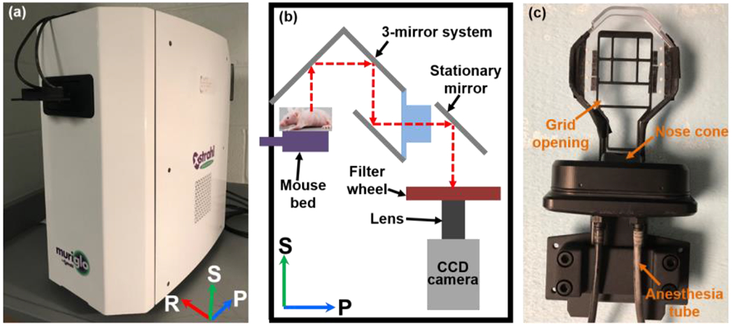
The (a) photo and (b) schematic of MuriGlo; the BL signal emitted from mouse is directed by a motorized 3-mirror and then a stationary mirror to the filter and lens-camera setup. The filters enable multi-spectral BLI acquisition. The 3-mirror system can rotate 360° around animal and capture multi-projection images. (c) The photo of transportable mouse bed; the grid opening is designed for acquisition of BL signal at 180°. Abbreviation: S = superior, P = posterior, R = right for a mouse at supine position placed on the mouse bed.
To transfer the animal between BLT system and SARRP, we used a transportable mouse bed (Figure 1c) consisting of a bed base with grid opening, eight ball bearings (BBs), a nose cone, and two anesthesia tubes. The grid opening on the bed base allows the BL signals passing through the mouse bed, which can be captured by the 3-mirror system at 180°. Two anesthesia tubes are connected to the nose cone, allowing the animal to be anesthetized during imaging, irradiation, and transportation between the systems. For BLI session, the bed is docked into the light-tight enclosure. For SARRP CBCT imaging and irradiation, the bed is fixed on the SARRP animal couch. Because the SARRP CBCT is used to generate tetrahedral mesh of imaged animal for BLT reconstruction and define the coordinate for radiation, the multi-projection BLIs were mapped onto the animal surface of the CBCT image and used as the input data for the BLT reconstruction. We used a pinhole camera model to establish the geometrical relationship between CBCT and 2D BLIs at a given projection23. The eight BBs attached on mouse bed can be identified in optical image, at −60°, −30°, 0°, 30° and 60° projections, with the LED as well as and in CBCT image to register the optical and CBCT coordinates. The BLT system was operated in close proximity (within 2 m) to the SARRP to minimize the potential disturbance of the animal position during the transport between systems.
2.2. Subcutaneous tumor model
The in vivo procedures were carried out in accordance with the Johns Hopkins Animal Care and Use Committee. Nude mouse (NCr nude, female, 6-8 weeks old; Taconic Biosciences, Rensselaer, NY) was anesthetized with intraperitoneal (IP) injection of Ketamine (100 mg/mL, 90 mg/kg dosage per mouse; KetaVed®; Vedco Inc., St. Joseph, MO) and Xylazine (100 mg/mL, 10 mg/kg dosage per mouse; XylaMed™; Bimeda, Inc., Le Sueur, MN) mixture or isoflurane (Fluriso™, VETOne®; MWI Animal Health, Boise, ID) starting at 3-5% for induction and then 1-3% during subcutaneous injection. To establish the subcutaneous tumor, 5 × 10⁵ BxPC3-Red-FLuc (PerkinElmer, Waltham, MA) cells suspended in 100 μL of phosphate buffer solution (PBS) were subcutaneously injected into the right flank of nude mouse.
2.3. Orthotopic pancreatic tumor model
For the orthotopic pancreatic tumor implantation, a tumor fraction was cut from a subcutaneous tumor described in Sec. 2.2. To ensure we had enough tumor tissue for the implantation, we let the subcutaneous tumor grow until the tumor reached around 10 mm in diameter.
To prepare the orthotopic tumor implantation, we euthanized the mouse bearing subcutaneous tumor, immediately harvested the tumors from the mouse flank, cut them into small fractions at 3 mm in diameter (Figure 2a), and temporarily preserved the tumor fractions in cold PBS (kept in ice) for the implantation. A small piece of titanium wire (34 gauge; TEMCo Industrial, Fremont, CA) was inserted into the center of the tumor fraction.
Figure 2.
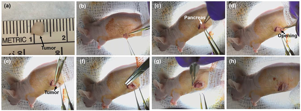
The surgical steps of orthotopic pancreatic tumor implantation; (a) a fraction of tumor tissue at approximately 3 mm in diameter was cut from a subcutaneous tumor. (b) The openings of skin and peritoneum were made on the left flank of mouse in sequence. (c) The spleen and pancreas were gently exteriorized, and the pancreas was spread out on the skin. (d) A small pocket was created in the pancreatic parenchyma. (e) The tumor fraction was inserted into the pancreas pocket. (f) A 7-0 suture was used for stitching the tumor fraction firmly inside the pancreas pocket and closing the pocket. (g) The spleen and pancreas were placed back into the abdominal cavity. (h) The incisions on the peritoneum and skin were closed in sequence.
The animal was subject to analgesia, Buprenorphine-SR LAB (1 mg/mL, 1 mg/kg dosage per mouse; Zoopharm, Windsor, CO), and then was anesthetized by IP injection of Ketamine and Xylazine (90mg/kg and 10 mg/kg) mixture or with isoflurane starting at 3-5% for induction purpose and at 1-3% during the surgical procedure. The surgical site was located at the skin on animal left flank, around spleen position, which is posterior to the last rib. Prior to incision, the surgical site was sterilized with povidone-iodine solution (10%, 1% available iodine; Dynarex, Orangeburg, NY), and reflexes were tested by paw-pinch to determine if the mouse was well-under sedation. An 8-12 mm transverse incision was made on the skin at the surgical site, and another 8-12 mm transverse incision was made on the peritoneum right under the skin incision (Figure 2b). The spleen and pancreas were gently exteriorized, and the pancreas was spread out on the skin (Figure 2c). A small pocket was created in the pancreatic parenchyma (Figure 2d), and a tumor fraction was inserted into the tissue pocket (Figure 2e). We used 7-0 suture (Nylon; Aros Surgical Instruments Corp., Newport Beach, CA) to stitch the tumor fraction in between two layers of pancreatic parenchyma, and closed the tissue pocket (Figure 2f). After placing the pancreas and spleen back into the abdominal cavity (Figure 2g), we closed the incisions on the peritoneum and skin using a 4-0 suture (Nylon; Ethicon Inc., Somerville, NJ) (Figure 2h). The procedure of the orthotopic pancreatic tumor implantation is available at https://www.youtube.com/watch?v=bWjDVhXJ_xY.
2.4. In vivo 2D BLI and 3D BLT
For the subcutaneous model, mice were prepared with imaging session at 2, 3 and 5 weeks after cell injection. For the orthotopic model, we conducted the imaging session at 0.5, 1, 1.5, 2, 3, 4, 5 and 7 weeks after the tumors were implanted. To investigate the potentiality of the orthotopic tumor movement during animal transport between the MuriGlo and SARRP system, two SARRP CBCT images were acquired before and after the BLI acquisition at each designated imaging time points. The titanium wire placed in the tumor was used as the marker to investigate any potential tumor movement during the image course.
For BLI, D-luciferin (120 μL, 30 mg/mL, PerkinElmer, Waltham, MA) was administrated via IP injection. For the subcutaneous tumor BLI, we fixed the animal at prone position, and the subcutaneous tumor was orientated towards 0° projection direction. Since the orthotopic pancreatic tumor is closer to the surface of abdomen than that of dorsum, we chose the supine position for BLI. Multi-projection and multi-spectral BLIs were acquired for both tumor models. The published method using unfiltered image in between the spectral images for recording time-resolved BL signal curve to correct temporal signal variation in vivo was applied for the BLI acquisition16. For multi-projection acquisition, we linked the time-resolved curves between two projections by extrapolating the light intensity from the first curve to the time point when the first unfiltered image at the second projection was measured. Due to the locations of subcutaneous and orthotopic tumors, only weak or no signal were detected at 90° projection. We acquired the projection image in the order of 0°, −90°, 180°, 90°, and for cases without the 90° projection signal, we used 3 projections 0°, −90°, 180° for reconstruction instead. At each projection, four BLIs at 590, 610, 630, and 650 nm were acquired. The first BLI was acquired 10 min after the D-luciferin injection. The BLIs were corrected by the normalized spectral weights of the BxPC3-RedFluc cells (0.67, 1, 0.85, and 0.51 for 590, 610, 630, and 650 nm, respectively). To eliminate the need of modeling light propagation from the animal surface to the camera in our non-contact imaging geometry, we applied a recently published spectral derivative reconstruction algorithm24 for target volume reconstruction. Due to the use of surface images ratio at adjacent wavelengths for reconstruction, the calibration for the intensity non-uniformity from lens-camera setup was not required. Since the signal at 590 nm was only around 1/4 of that at other wavelengths for orthotopic model, the use of four wavelengths data with spectral derivative algorithm will cause the failure of reconstruction. Therefore, we used three wavelengths (610, 630, and 650 nm) data for the orthotopic tumor BLT reconstruction. In contrast, the signal at 590 nm from the subcutaneous model did not suffer the strong optical absorption as we seen from the orthotopic model. We therefore used four wavelengths (590, 610, 630, and 650 nm) data for the subcutaneous tumor reconstruction.
3. RESULTS
For the case of subcutaneous tumor model (Figure 3), a mouse imaged with BLT at the 3rd week after cell injection was used as the representative case to demonstrate the BLT reconstruction. We used a threshold of 10% maximum of the BLT reconstruction value to confine the reconstructed tumor volume. As shown in Figure 3, the BLT volume is 47 mm3, and the CBCT volume is 38 mm3. The difference between these two volumes is 24%. The deviation between the CoMs of BLT and CBCT volumes is 1.6 mm.
Figure 3.

Mouse was proceeded with BLT at the 3rd week after cell injection. We used four wavelengths (590, 610, 630, and 650 nm) for the reconstruction, and applied 10% threshold to determine the BLT volume. The BLT-reconstructed volume was overlapped on SARRP CBCT image at (a) coronal, (b) sagittal, and (c) transverse views.
Three mice were used to investigate the position of the orthotopic pancreatic tumor during our imaging process, where animal transport and potential internal organ movement were involved. We first imaged the animal using SARRP CBCT, transported the animal to MuriGlo for BLI, and then reimaged the animal using SARRP CBCT, which involves animal transport from SARRP to MuriGlo then back to SARRP. The length of the total process is in between 10 to 30 minutes mainly depending on the BLI acquisition time. It is worthwhile to mention that there is an additional animal transport process from SARRP to MuriGlo, compared to normal BLT imaging process which only requires the animal transport from MuriGlo to SARRP. It renders that we may introduce additional animal position disturbance in this test. The titanium wire was used to track the tumor location. Figure 4(a–b) shows a representative result of the titanium wire position, at ventral-to-dorsal (VD) view, shown in the SARRP CBCT images before and after the BLI acquisition, respectively. The deviation of center of mass (CoM) location of the titanium wire, taken as the tumor location, during the animal transport is 0.32 ± 0.09 mm. This result was acquired from the data 1.5 week after tumor implantation. The analysis will be extended to wider range of imaging time points after tumor implantation and large number of animals.
Figure 4.
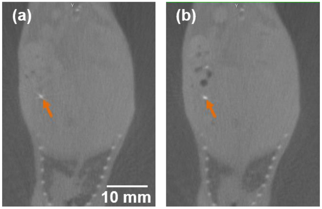
SARRP CBCT images at VD view (a) before and (b) after the BLI acquisition; the titanium wire (orange arrow) centered at the orthotopic pancreatic tumor was used as the marker to identify the tumor location.
The longitudinal 2D BLIs (n = 3) for orthotopic pancreatic tumors are shown in Figure 5. To minimize the effect of in vivo time-resolved signal variation, we use the first unfiltered images, 10 mins after the luciferin injection, cross all the mice and data points for the Figure 5 demonstration. To further compare the BLIs at different time points for a given mouse, we normalized the images with the corresponding image acquisition time. In general, we observed not only the intensity of BL signal increased, but also the area of BL pattern expanded along with the time of tumor growth. However, we also noted significant decreases of BL signals at 0° projection (e,g. Figure 5b5–b6, 5c3–c6). This phenomenon could be attributed to the tumor moving into different abdomen region, which makes it challenging to monitor the tumor growth using the 2D BLI at single projection. Figure 6 shows the unfiltered BLIs of Mouse #2 at 3 and 4 weeks after tumor implantation at 0 and 180° projections (at different amplitude scale, corresponding to Figure 5b5–b6). It clearly demonstrates that between each image session at different days, abdominal tumor can move to different location. Therefore, 2D BLI is not an ideal image modality to quantity the tumor growth/volume monitoring.
Figure 5.
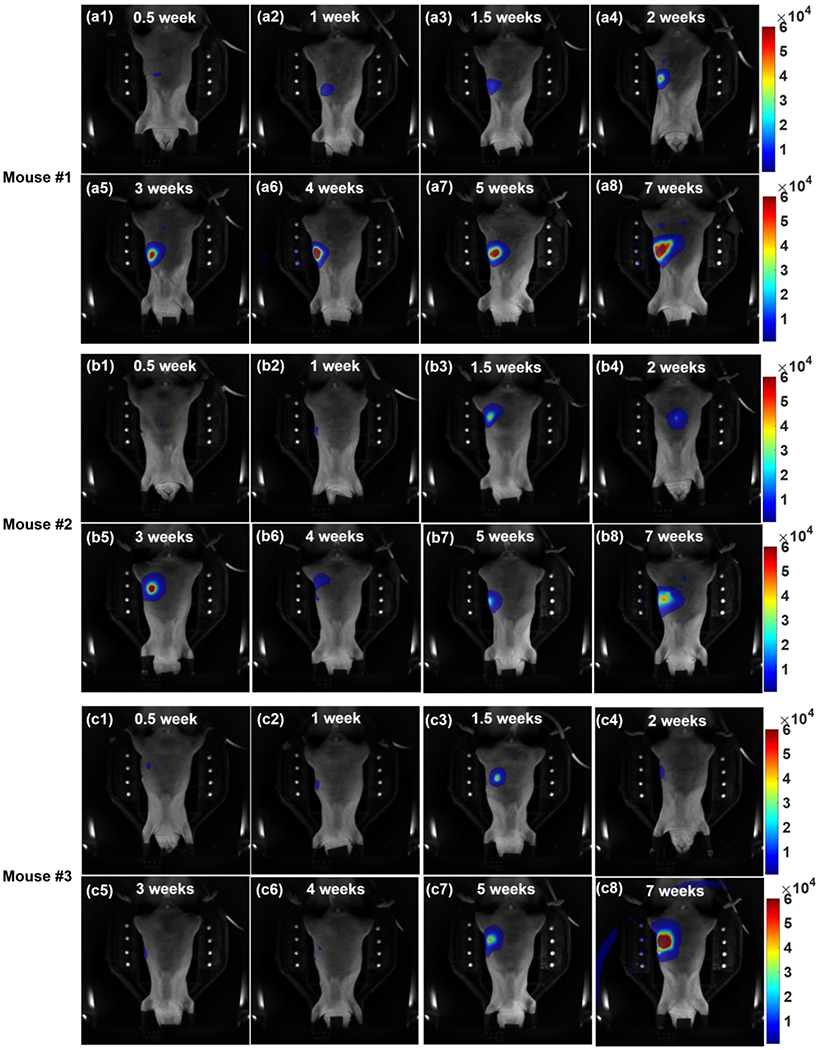
The unfiltered BLIs of three mice (a1-8, #1; b1-8, #2; c1-8, #3) at 0° projection; The images are arranged in the order of (1) 0.5, (2) 1, (3) 1.5, (4) 2, (5) 3, (6) 4, (7) 5, and (8) 7 weeks after the tumor implantation. The intensity of BL signal increased and the area of BL pattern expanded overtime. Because the pancreatic tumor could move to different positions around the abdomen region, it would affect the intensity and the pattern of BL signal at the 0° projection image (b5-b6, and c3-c6). The artifact due to strong BLI signal is seen in Figure 5c8.
Figure 6.

The unfiltered BLIs of Mouse #2 at (a) 3 and (b) 4 weeks after the tumor implantation at (a1 and b1) 0 and (a2 and b2) 180° projections; it clearly shows that the tumor can move to different locations and multi-projection BLT is necessary to quantify the tumor location in 3D.
Figure 7 demonstrates our initial study of BLT reconstruction for orthotopic pancreatic tumor. The mouse at 1.5 weeks after tumor implantation was used as the representative case. The BLI of surface emission was mapped on the mesh of mouse body generated from SARRP CBCT image (Figure 7a). The BLT-reconstructed tumor volume subject to a threshold of 60% maximum of the BLT reconstruction value is 17 mm3 (Figure 7b). Since the tumor likely went through angiogenesis after implantation, we hypothesized that it would not grow significantly before the imaging. Therefore, we used the tumor size at the time of implantation (14mm3) as the approximated volume to validate the BLT volume. The difference between these two volumes is 21%. Further tumor size estimation will be based on the ongoing MRI study. The deviation between the CoMs of BLT-reconstructed tumor volume and titanium wire is 2.2 mm.
Figure 7.

Initial study of BLT reconstruction for the orthotopic pancreatic tumor model (mouse #1 1.5 weeks after the tumor implementation); (a) multi-projection BLI at 630 nm mapped on the mesh of mouse body; (b) VD view of the mouse body mesh overlapped with the BLT-reconstructed tumor volume and titanium wire; we used the data of three wavelengths (610, 630, and 650 nm) for the reconstruction, and applied a threshold of 60% maximum to determine the BLT volume. The titanium wire was used for identifying the tumor location.
4. DISCUSSION
The integration of clinically-relevant autochthonous PDAC-GEMM with advanced BLT-guided SARRP irradiation will greatly enhance the progress of pre-clinical oncology research on the development of new treatment options for PDAC, and offer unique opportunities to start important animal trials closely related to clinic studies. This is particularly important at present when radiation is being tested not only for its efficacy for local control but also as an effective modulator of other therapeutic mechanisms, such as immunotherapy.
Before working on the complex PDAC-GEMM, we planned to validate our BLT target localization using subcutaneous and orthotopic pancreatic tumor models. In this work, we have demonstrated the process of establishing the subcutaneous and orthotopic pancreatic tumor model (Figure 2). Despite the limited data points, our current data shows that with careful animal immobilization and handling, minimum target position disturbance was introduced during our imaging procedure (< 0.5 mm, Figure 4) which involves the animal transport between systems. This uncertainty of target position during our imaging process can be considered as part of radiation margin design for the BLT-guided irradiation. However, the day-to-day location variation for an abdominal tumor can be significant (e.g. Figure 5b5–b6, 5c3–c6, and 6). It renders that 3D BLT with multiple-projection is needed to accurate quantity the tumor volume and location, particular to guide irradiation for precise radiation research. Nevertheless, a systematic study is needed to further study the pancreatic tumor movement.
The BLT reconstruction studies for the subcutaneous (Figure 3) and orthotopic (Figure 7b) models show the BLT localization of pancreatic tumor can be resolved at approximately 2 mm accuracy, and the tumor volume can be delineated within 25% difference compared with the ground truths. The development of reconstruction algorithm and threshold method are still on going to improve our BLT reconstruction for the pancreatic tumor.
In conclusion, we established subcutaneous and orthotopic pancreatic tumor models, investigated the movement of the orthotopic tumor during our imaging process, longitudinally monitored the orthotopic tumor growth with 2D BLI, and reconstructed the 3D BLT volume for both models. Completion of the study for subcutaneous and orthotopic models will offer us valuable knowledge for BLT-guided PDAC-GEMM radiation research.
5. ACKNOWLEDGEMENTS
The authors would like to thank the funding support from NIH/NCI, R21CA223403, R37CA230341, R01CA240811, and P30CA006973.
REFERENCES
- [1].Bray F, Ferlay J, Soerjomataram I, Siegel RL, Torre LA, and Jemal A, “Global cancer statistics 2018: GLOBOCAN estimates of incidence and mortality worldwide for 36 cancers in 185 countries,” CA-Cancer J. Clin 68(6), 394–424 (2018). [DOI] [PubMed] [Google Scholar]
- [2].“Chemoimmunotherapy and radiation in pancreatic cancer (CRIT),” ClinicalTrials.gov. Identifier: NCT01903083.
- [3].“Pancreatic tumor cell vaccine (GVAX), low dose cyclophosphamide, fractionated stereotactic body radiation therapy (SBRT), and FOLFIRINOX chemotherapy in patients with resected adenocarcinoma of the pancreas,” ClinicalTrials.gov. Identifier: NCT01595321.
- [4].“Immune checkpoint inhibition (Tremelimumab and/or MEDI4736) in combination with radiation therapy in patients with unresectable pancreatic cancer,” ClinicalTrials.gov. Identifier: NCT02311361.
- [5].Wong J, Armour E, Kazanzides P, Iordachita U, Tryggestad E, Deng H, Matinfar M, Kennedy C, Liu ZJ, Chan T, Gray O, Verhaegen F, McNutt T, Ford E, and DeWeese TL, “High-resolution, small animal radiation research platform with X-ray tomographic guidance capabilities,” Int. J. Radiat. Oncol. Biol. Phys 71(5), 1591–1599 (2008). [DOI] [PMC free article] [PubMed] [Google Scholar]
- [6].Matinfar M, Ford E, Iordachita I, Wong J, and Kazanzides P, “Image-guided small animal radiation research platform: Calibration of treatment beam alignment,” Phys. Med. Biol 54(4), 891–905 (2009). [DOI] [PMC free article] [PubMed] [Google Scholar]
- [7].Ford EC, Achanta P, Purger D, Armour M, Reyes J, Fong J, Kleinberg L, Redmond K, Wong J, Jang MH, Jun H, Song HJ, and Quinones-Hinojosa A, “Localized CT-Guided Irradiation Inhibits Neurogenesis in Specific Regions of the Adult Mouse Brain,” Radiat. Res 175(6), 774–783 (2011). [DOI] [PMC free article] [PubMed] [Google Scholar]
- [8].Herter-Sprie GS, Korideck H, Christensen CL, Herter JM, Rhee K, Berbeco RI, Bennett DG, Akbay EA, Kozono D, Mak RH, Makrigiorgos GM, Kimmelman AC, and Wong KK, “Image-guided radiotherapy platform using single nodule conditional lung cancer mouse models,” Nat. Commun 5, 5870 (2014). [DOI] [PMC free article] [PubMed] [Google Scholar]
- [9].Chandra A, Lin T, Tribble MB, Zhu J, Altman AR, Tseng WJ, Zhang YJ, Akintoye SO, Cengel K, Liu XS, and Qin L, “PTH1-34 alleviates radiotherapy-induced local bone loss by improving osteoblast and osteocyte survival,” Bone 67, 33–40 (2014). [DOI] [PMC free article] [PubMed] [Google Scholar]
- [10].Seifert L, Werba G, Tiwari S, Ly NNG, Nguy S, Alothman S, Alqunaibit D, Avanzi A, Daley D, Barilla R, Tippens D, Tones-Hemandez A, Hundeyin M, Mani VR, Hajdu C, Pellicciotta I, Oh P, Du K, and Miller G, “Radiation therapy induces macrophages to suppress T-cell responses against pancreatic tumors in mice,” Gastroenterology 150(7), 1659–1672 (2016). [DOI] [PMC free article] [PubMed] [Google Scholar]
- [11].Sievert W, Stangl S, Steiger K, and Multhoff G, “Improved overall survival of mice by reducing lung side effects after high-precision heart irradiation using a small animal radiation research platform,” Int. J. Radiat. Oncol. Biol. Phys 101(3), 671–679 (2018). [DOI] [PubMed] [Google Scholar]
- [12].Thorne SH, and Contag CH, “Using in vivo bioluminescence imaging to shed light on cancer biology,” Proc. IEEE 93(4), 750–762 (2005). [Google Scholar]
- [13].O’Neill K, Lyons SK, Gallagher WM, Curran KM, and Byme AT, “Bioluminescent imaging: A critical tool in pre-clinical oncology research,” J. Pathol 220(3), 317–327 (2010). [DOI] [PubMed] [Google Scholar]
- [14].Close DM, Xu TT, Sayler GS, and Ripp S, “In vivo bioluminescent imaging (BLI): Noninvasive visualization and interrogation of biological processes in living animals,” Sensors 11(1), 180–206 (2011). [DOI] [PMC free article] [PubMed] [Google Scholar]
- [15].Yu JJ, Zhang B, Iordachita II, Reyes J, Lu ZH, Brock MV, Patterson MS, Wong JW, and Wang KKH, “Systematic study of target localization for bioluminescence tomography guided radiation therapy,” Med. Phys 43(5), 2619–2629 (2016). [DOI] [PMC free article] [PubMed] [Google Scholar]
- [16].Zhang B, Wang KKH, Yu JJ, Eslami S, Iordachita I, Reyes J, Malek R, Tran PT, Patterson MS, and Wong JW, “Bioluminescence tomography-guided radiation therapy for preclinical research,” Int. J. Radiat. Oncol. Biol. Phys 94(5), 1144–1153 (2016). [DOI] [PMC free article] [PubMed] [Google Scholar]
- [17].Zhang B, Wong JW, Iordachita II, Reyes J, Nugent K, Tran PT, Tuttle SW, Koumenis C, and Wang KKH, “Evaluation of on- and off-line bioluminescence tomography system for focal irradiation guidance,” Radiat. Res 186(6), 592–601 (2016). [DOI] [PMC free article] [PubMed] [Google Scholar]
- [18].Shi J, Udayakumar TS, Wang Z, Dogan N, Pollack A, and Yang Y, “Optical molecular imaging-guided radiation therapy part 1: Integrated x-ray and bioluminescence tomography,” Med. Phys 44(9), 4786–4794 (2017). [DOI] [PubMed] [Google Scholar]
- [19].Shi J, Udayakumar TS, Xu K, Dogan N, Pollack A, and Yang Y, “Bioluminescence Tomography Guided Small-Animal Radiation Therapy and Tumor Response Assessment,” Int. J. Radiat. Oncol. Biol. Phys 102(4), 848–857 (2018). [DOI] [PubMed] [Google Scholar]
- [20].Deng Z, Xu X, Garzon-Muvdi T, Xia Y, Kim E, Belcaid Z, Luksik A, Maxwell R, Choi J, Wang H, Yu J, Iordachita I, Lim M, Wong JW, and Wang KK-H, “In Vivo Bioluminescence Tomography Center of Mass-Guided Conformal Irradiation,” Int. J. Radiat. Oncol. Biol. Phys (2020), DOI: 10.1016/j.ijrobp.2019.11.003. [DOI] [PMC free article] [PubMed] [Google Scholar]
- [21].Kuo C, Coquoz O, Troy TL, Xu H, and Rice BW, “Three-dimensional reconstruction of in vivo bioluminescent sources based on multispectral imaging,” J. Biomed. Opt 12(2), 024007 (2007). [DOI] [PubMed] [Google Scholar]
- [22].Dehghani H, Davis SC, Jiang SD, Pogue BW, Paulsen KD, and Patterson MS, “Spectrally resolved bioluminescence optical tomography,” Opt. Lett 31(3), 365–367 (2006). [DOI] [PubMed] [Google Scholar]
- [23].Zhang B, Iordachita I, Wong JW, and Wang KKH, “Multi-projection bioluminescence tomography guided system for small animal radiation research platform (SARRP),” Proc. SPIE 9701, 97010J (2016). [Google Scholar]
- [24].Dehghani H, Guggenheim JA, Taylor SL, Xu XK, and Wang KKH, “Quantitative bioluminescence tomography using spectral derivative data,” Biomed. Opt. Express 9(9), 4163–4174 (2018). [DOI] [PMC free article] [PubMed] [Google Scholar]