

Abstract
We investigated the adsorption of three related cyano‐functionalized tetraphenyl porphyrin derivatives on Cu(111) by scanning tunneling microscopy (STM) in ultra‐high vacuum (UHV) with the goal to identify the role of the cyano group and the central Cu atom for the intermolecular and supramolecular arrangement. The porphyrin derivatives studied were Cu‐TCNPP, Cu‐cisDCNPP, and 2H‐cisDCNPP, that is, Cu‐5,10,15,20‐tetrakis‐(p‐cyano)‐phenylporphyrin, Cu‐meso‐cis‐di(p‐cyano)‐phenylporphyrin and 2H‐meso‐cis‐di(p‐cyano)‐phenylporphyrin, respectively. Starting from different structures obtained after deposition at room temperature, all three molecules form the same long‐range ordered hexagonal honeycomb‐type structure with triangular pores and three molecules per unit cell. For the metal‐free 2H‐cisDCNPP, this occurs only after self‐metalation upon heating. The structure‐forming elements are pores with a distance of 3.1 nm, formed by triangles of porphyrins fused together by cyano‐Cu‐cyano interactions with Cu adatoms. This finding leads us to suggest that two cyano‐phenyl groups in the “cis” position is the minimum prerequisite to form a highly ordered 2D porous molecular pattern. The experimental findings are supported by detailed density functional theory calculations to analyze the driving forces that lead to the formation of the porous hexagonal honeycomb‐type structure.
Keywords: coordinated networks, cyano functionalization, density functional theory calculations, porphyrins, scanning tunneling microscopy
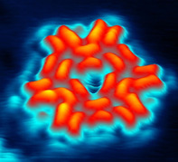
Snowflake‐shaped porphyrins: Twelve doubly cyano‐functionalized Cu‐tetraphenylporphyrins form a snowflake‐like structure around a macropore, as observed by scanning tunneling microscopy at room temperature.
Introduction
It is still an ongoing challenge to organize matter on the molecular or even atomic scale. In this regard, the topic of self‐assembled supramolecular networks of organic molecules on noble‐metal surfaces developed as a vivid research field over the last two decades. Molecular self‐assembly, based on molecular recognition concepts in supramolecular chemistry,1 aims at design, synthesis, and understanding of the assembly of a discrete number of molecular entities into larger ensembles. In the new supramolecular entities with larger shapes and sizes, the spatial organization of the functional building blocks is controlled by intermolecular forces such as hydrogen bonding,2 π–π stacking,3 dipolar coupling,4 metal coordination,5 and dispersion forces, all of which are weaker than covalent bonding. Molecular self‐assemblies and their properties on surfaces not only depend on the intermolecular interactions but also on the adsorbate‐substrate interactions; therefore they can be tuned by modifications within the molecules6 and by the choice of the underlying substrate.7
If it comes to the directed self‐assembly toward functional molecular architectures, porphyrins8 appear to be a particularly suitable class of molecules, since they are omnipresent in nature, for example in chlorophyll (Mg‐center)9 and heme (Fe‐center).10 Porphyrins consist of a tetrapyrrolic macrocycle with a central cavity, which can coordinate a variety of metal atoms.9, 10, 11 Owing to these properties, porphyrins adsorbed at metal surfaces offer a rich playground for the detailed investigation and manipulation of desired systems. Recently, the attachment of one or more cyano‐functionalized groups to porphyrins turned out to be particularly interesting, because the negatively charged N‐atoms can interact through different bonding motifs with neighboring molecules. Notably, cyano groups cannot only contribute in hydrogen bonding and dipolar coupling, but also can coordinate to different metals.4, 12 Furthermore, it was shown that the electron withdrawing effect of the peripheral cyano groups significantly influences the self‐metalation of corresponding metal‐free porphyrin derivatives on Cu(111).12a
In addition to the already reported individual molecules (0D)12d and molecular chains (1D)12b of cyano‐functionalized porphyrins, we herein report the formation of peculiar porous networks (2D), which is again triggered by the functional cyano groups. Previously, 2D molecular porous networks were reported using different classes of organic molecules on single crystal metal surfaces.13 These 2D molecular porous networks are especially interesting, since they have a high potential as “host template” for functional guest molecules, for example, to study the dynamics of guest binding within the pore or to localize them even at elevated temperatures for the manipulation by an STM tip. Moreover, the pores may also serve as nanoreactors.14
Generally, the self‐assembly of ordered supramolecular networks depends on the nature and functionality of the corresponding molecular building blocks, the choice of the substrate and the applied conditions. For example, the porous networks formed by trimesic acid (TMA) and its larger relative 1,3,5‐benzene‐tribenzoic acid (BTB) have been studied on surfaces like HOPG15 and Au(111).16 Moreover, the porous networks stabilized by metal coordination captured increasing attention due to metal‐ligand bonding, and thus its stability is stronger than usual hydrogen‐bonded porous networks. More often, for the formation of metal‐organic networks Fe, Co, Ni, or Cu atoms are introduced as linker metals for co‐adsorbed organic molecules. Aside from directly introduced transition metal atoms, adatoms from the surface, onto which molecules are deposited, can be used for metal‐organic coordination. Recently, examples for this type of interactions have been reported by Lepper et al. on Cu(111)12b and by Gottardi et al. on Au(111).17
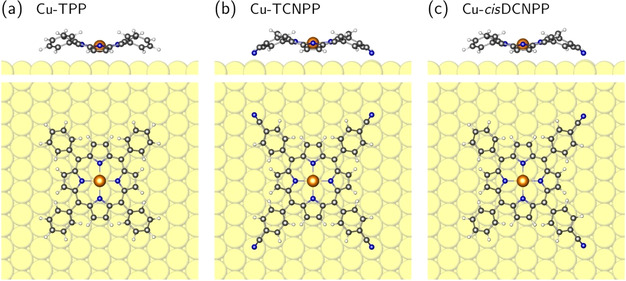
Figure 1 depicts the chemical structures of Cu‐TCNPP, Cu‐cisDCNPP, and 2H‐cisDCNPP, in which fourfold and twofold (cis)‐cyano‐phenyl groups are attached to the meso‐position of the porphyrin core. In this contribution, we will show that the depicted metalated species tend to self‐assemble into a peculiar well‐ordered porous commensurate array, which is stable at RT. We will discuss the importance of the cyano‐cis conformation as a prerequisite for the latter structure as well as the role of the metalated center.
Figure 1.
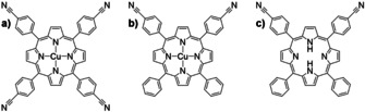
Chemical structure of different cyano‐functionalized porphyrins: (a) Cu‐TCNPP, (b) Cu‐cisDCNPP, and (c) 2H‐cisDCNPP.
The adsorption of the different molecules was studied by scanning tunneling microscopy (STM) and density functional theory (DFT) calculations. The DFT calculations are based on a modified dispersion correction scheme, which gave very accurate results for binding energies and structures of aromatic molecules on Cu and Ag surfaces in a recent benchmark study.18, 19 Details of the methods and the synthesis of the molecules are provided in the Supporting Information.
Results and Discussion
Cu‐TCNPP on Cu(111):
Figure 2 a depicts an STM image of Cu‐TCNPP deposited on Cu(111) at RT, with an average coverage of 0.0084 ML (1 ML refers to one adsorbate molecule per surface atom). One can clearly distinguish two prominent molecular ordering patterns, namely a 2D hexagonal honeycomb‐type motif and a 1D linear double‐row motif. The self‐assembled supramolecular ordered islands are often connected to step edges, which indicates that the steps are energetically favored adsorption sites, which act as nucleation centers.11e While no isolated Cu‐TCNPP species could be imaged at RT, we observe clear indications for the existence of very mobile molecules on the surface, for example, attaching and detaching molecules and noisy streaks appearing in the fast scanning direction of the STM. The latter observation is attributed to fast Cu‐TCNPP moving molecules, which can be interpreted as a two‐dimensional (2D) gas phase.11a Similar observations have been reported for copper(II)‐tetraphenylporphyrin (Cu‐TPP) on Cu(111) at RT.11a In addition to the described behavior, we observe an individual molecule diffusing towards and away from the hexagonal honeycomb‐type pattern in Figure 2 a (indicted by an arrow; see also Figure S1 in the Supporting Information). This molecule moves along one of the high‐symmetry crystallographic directions of the Cu(111) surface and is identified as 2H‐TCNPP,12b which is a residue stemming from the synthesis of Cu‐TCNPP. The 2H‐TCNPP molecule appears as four bright lobes in the periphery and two dominating protrusions in the center. The diffusion of individual isolated metal‐free porphyrins along high‐symmetry crystallographic directions at RT is a common observation on Cu(111).11b, 11e
Figure 2.
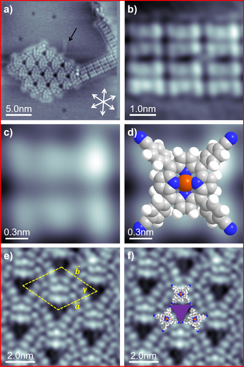
(a) Average frame of an STM movie (15 consecutively recorded images) of Cu‐TCNPP, deposited and measured at RT, showing a 1D linear parallel motif and a 2D porous hexagonal honeycomb‐type motif (30×30 nm2, U bias=−1 V, I set=28.8 pA). (b) Short 1D parallel molecular chains (5×5 nm2, U bias=−1 V, I set=28.8 pA). (c) High resolution STM image of a single Cu‐TCNPP molecule with six protrusions, which are ascribed to the two iminic pyrrole groups (center) and the 4 phenyl (peripheral) groups (1.5×1.5 nm2, U bias=−1 V, I set=28.8 pA). (d) Single Cu‐TCNPP molecule overlaid with a molecule model (1.5×1.5 nm2, U bias=−1 V, I set=28.8 pA). (e) STM image of the highly ordered 2D porous honeycomb‐type pattern with the lattice vectors of the unit cell indicated as dashed yellow lines, respectively (10×10 nm2, U bias=−1 V, I set=29 pA). (f) STM image of (e) is overlaid with scaled models of Cu‐TCNPP molecules.
In the following, we will discuss the appearance of individual Cu‐TCNPP molecules in the two motifs. The molecules in the 1D linear double‐row motif are shown in Figure 2 b and 2c on enlarged scales; they appear as six distinguishable, clearly recognizable protrusions, which are arranged in two parallel groups of three. By comparison with the chemical structure (c.f. Figure 1 a) and STM reports concerning metallo‐porphyrins in literature,8, 9, 10, 11 the outer four protrusions are assigned to the peripheral phenyl substituents, and the two central ones to the slightly bent up pyrrole groups; this is evident from Figure 2 d, where the STM image from Figure 2 c is overlaid with a scaled molecule model. The overall intramolecular conformation can be described as saddle‐shape conformation with the pyrrole groups tilted out of the macrocyclic plane.20 The elongated depression (dark line) between two parallel groups of three protrusions is referred to as molecular axis; it is aligned to one of the high‐symmetry crystallographic directions of the Cu(111) substrate.
Generally, the intramolecular conformation of TPPs on a surface is determined by a subtle balance between molecule‐surface and molecule‐molecule interactions as well as steric forces within the molecule. The saddle‐shape conformation is common for TPPs and slightly modified TPPs on a variety of surfaces. In contrast, metal‐free 2H‐TPP21 and the corresponding cyano‐functionalized species 2H‐(5‐mono‐(p‐cyanophenyl))‐(10,15,20‐triphenyl)‐porphyrin (2H‐MCNPP), 2H‐cisDCNPP, and 2H‐TCNPP12a, 12b exhibit a very peculiar “inverted” structure on Cu(111), which is characterized by direct N−Cu bonds and two nearly upright pyrrole groups.22
Next, we analyze the supramolecular arrangement in the 2D hexagonal honeycomb‐type motif in detail. Figure 2 e shows a high resolution image clearly resolving the sub‐molecular features and the highly ordered network with regular triangular pores. The structure can be described with a primitive hexagonal unit cell (γ=60°±2°) containing 3 molecules and lattice vectors of 3.0±0.15 nm. In order to further elucidate the supramolecular structure and the intermolecular network, the STM image is overlaid with scaled models of Cu‐TCNPP in Figure 2 f. From this comparison, it is evident that neighboring cyano groups face each other at the corners of the triangular pores. Notably, the molecules enclosing the triangular pores are aligned along the three high‐symmetry crystallographic directions of the Cu(111) surface.
The arrangement of the cyano groups at the corners of the triangular pores indicates that the observed supramolecular network of Cu‐TCNPP on Cu(111) is not due to the mutual stabilization via attractive intermolecular interactions, which was proposed for the metal‐free 2H‐TCNPP on Ag(111).12b Considering the polarity of the cyano groups, a direct CN−NC interaction is not expected to be energetically favorable. Furthermore, we interpret that the commonly observed T‐type and π–π intermolecular stacking of porphyrin derivatives are not in line with the relatively large distance of peripheral cyano groups.3, 4, 23 For the same reasons, we also rule out the known binding interaction for cyano groups, namely, via hydrogen bonds and dipolar coupling.4, 12d, 12e, 18
We rather propose that the terminating C−N groups are linked through native Cu adatoms. Indeed, the lone pair electrons provided by the N atoms of the functionalized cyano end groups possess high binding affinity towards transition metals.24 This mechanism has been reported frequently for N‐terminated organic molecules for metal‐organic network formation, since the Cu(111) surface is known to offer adequate native adatoms.12d, 25 We suggest that the native adatoms at the corners of the triangles fuse together two porphyrins by cyano‐Cu‐cyano interactions, and thereby stabilize the ordered 2D porous honeycomb‐type networks (for details see DFT calculations below). Three Cu‐TCNPP molecules are rotated by 60° with each other forming the regular triangular pores. The fact that the adatoms located at the corners of the triangular cavities are not visible in the STM images has been reported before for 3d‐block transition metals within 2D porous networks on metal surfaces.12b, 12d, 24, 26
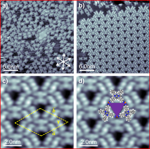
After analyzing the appearance of individual Cu‐TCNPPs and their supramolecular arrangement, we performed annealing experiments to probe the stability of the different phases. Figure 3 a shows the STM image acquired at RT after annealing at 400 K. Interestingly, we find a complete transformation to the monomodal appearance of the 2D hexagonal honeycomb‐type pattern, with no 1D linear double‐row motifs left.
Figure 3.
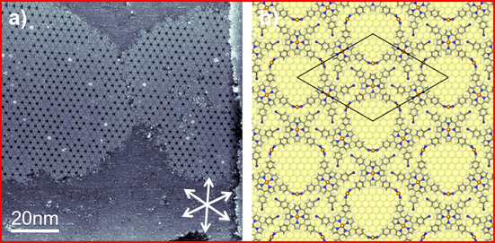
(a) A 100×100 nm2 STM image depicts the full monomodal transformation of Cu‐TCNPP after annealing at 400 K (U bias=−1 V, I set=30 pA); the high‐symmetry crystallographic <110> substrate directions are indicated as white double arrows. (b) DFT‐optimized structure of the porous honeycomb‐type network showing a hexagonal (7√3×7√3)R30° superstructure, in which the molecules are linked through Cu adatoms on Cu(111).
The observation of the extended long‐range ordered structure, which is perfectly aligned along the high symmetry directions of the substrate allows for further insights. The perfect alignment and the absence of any moiré pattern is a strong indication that the superstructure is commensurate with the underlying substrate. The driving force likely is that the linking Cu adatoms have a well‐defined adsorption site on the Cu(111) surface. In Figure 3 b, we depicted a structural model, which is based on the STM image in Figure 3 a, and on the detailed DFT calculations presented below. Note that since we are not able to determine the exact positions of the Cu‐TCNPP molecules on the Cu(111) lattice from our STM images, this information solely stems from the calculations. The primitive hexagonal unit cell corresponds to a (7√3×7√3)R30° superstructure, with a length of the lattice vector of 3.09 nm. In this structure, the porphyrins adsorb on bridge sites and the connecting Cu adatoms occupy threefold hollow sites (see below).
Further annealing to 450 K results in a loss of the long‐ranged ordered structure, and the observation of randomly oriented individual molecules, which display four pronounced protrusions; see Figure S2 in the Supporting Information. We tentatively assign our observations to the formation of intramolecular C−C bonds between the phenyl groups and the porphyrin core, after dehydrogenation of the corresponding carbon atoms.11a Similar reactions have been proposed for 2H‐TPP on Ag(111) after heating to above 525 K,6b, 27 for 2H‐TPP on Cu(111)28 and for 2H‐TCNPP on Pd/Cu(111).29 Moreover, from STM, we find that there is no long‐range order any more, but most of the reacted molecules are still aligned along one of the high symmetry substrate directions. This likely is due to specific interactions of the cyano groups with the substrate Cu atoms.
Cu‐cisDCNPP on Cu(111):
To gain deeper insight into the formation of 2D porous networks and in particular into the role of the cyano‐functionalized phenyl groups, we varied the number of cyano‐functionalized substitutions from four to two in cis‐configuration. Figure 4 a depicts an STM image of Cu‐cisDCNPP deposited and measured at RT on Cu(111) with an average coverage of 0.0067 ML. We observe characteristic structures with one or more pores, which show a large similarity to the 2D hexagonal honeycomb‐type motif observed for Cu‐TCNPP (see above). We distinguish triangular “monoflakes” with one pore, “biflakes” with two pores and “multiflakes” with more than 2 pores. The molecularly resolved image of a monoflake in Figure 4 b shows that the individual molecules within the flakes are characterized by two parallel elongated protrusions, which indicates a saddle‐shape conformation,21b identical to that proposed for Cu‐TCNPP. Notably, also a small number of monomers and dimers are visible, which are assigned to metal‐free 2H‐cisDCNPP molecules, which are most likely present in the Cu‐cisDCNPP material as residues of the synthesis process.
Figure 4.
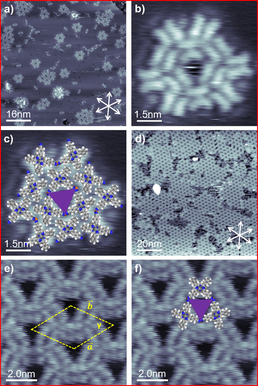
(a) A 80×80 nm2 STM image showing Cu‐cisDCNPP deposited and measured at RT (U bias=−1.02 V, I set=28.8 pA). (b, c) High resolution STM image showing a monoflake with molecular model superimposed (7.5×7.5 nm2, U bias=−1.02 V, I set=28.8 pA). (d) A 100×100 nm2 STM image depicts 2D porous network formation after a 400 K annealing step (U bias=−1.01 V, I set=29.5 pA). (e, f) Close‐up STM image with unit cell and tentative molecule model overlayed (10×10 nm2, U bias=−1.02 V, I set=28.8 pA).
In Figure 4 c, the STM image of the monoflake shown in Figure 4 b is superimposed with scaled models of Cu‐cisDCNPP. Three molecules, rotated to each other by 60°, form the central triangular pore of the monoflake. From the tentative overlay, it becomes apparent that the neighboring cyano groups face each other at the corners of the triangular pore, which is the identical arrangement as for Cu‐TCNPP (see above). Again, the three sides of the triangular pores reflect the three main high‐symmetry crystallographic directions of Cu(111). Along the lines discussed for Cu‐TCNPP, we propose that native Cu adatoms from the substrate stabilize the structure through local CN‐Cu‐NC motifs.
As a next step, we annealed the adsorbed layer to 400 K for 60 min. Figure 4 d depicts the STM image acquired at RT after annealing. Interestingly, the triangular porous “monoflakes”, “biflakes” and “multiflakes” are not observed anymore, but instead have undergone a transformation towards a long‐range‐ordered 2D porous hexagonal honeycomb‐type pattern. Its structure is within the margins of error identical to the one observed for Cu‐TCNPP. The comparison to Figure 3 a shows smaller domains, with areas of uncovered substrate in between. This observation is likely due to the low mobility of the larger flakes, which serve as nucleation centers for the larger long‐range‐ordered domains. Interestingly, all pores in Figure 4 d and 4 e are empty, which is in contrast to Figure 3 a, where some of the pores are filled by unidentified contaminations, which could originate from the synthesis process.
2H‐cisDCNPP on Cu(111):
To obtain further information on the formation of the observed long‐range ordered porous networks and in particular to evaluate the role of the central Cu atom, we also studied the adsorption of the metal‐free 2H‐cisDCNPP on Cu(111) at RT with an average coverage of 0.0168 ML. Figure 5 a depicts an STM image of 2H‐cisDCNPP deposited and measured at RT on Cu(111). The molecules do not form any long‐range ordered network, but are adsorbed as individual species. Each molecule appears as four bright lobes in the periphery, and two dominating protrusions in the center; the latter are hardly resolved and mostly appear as one longish protrusion. The molecular appearance and the general adsorption behavior is very similar to that of 2H‐TCNPP on Cu(111),12b where the intramolecular conformation is described by the so‐called “inverted” structure.21b In this structure, two opposite pyrrole rings are oriented perpendicular to the Cu surface, yielding the two bright central protrusions in the sub‐molecularly resolved STM image, similar as seen in Figure 5 a. The molecules are aligned along one of the high‐symmetry crystallographic directions of the substrate, which is due to a strong attractive site‐specific interaction between the iminic nitrogens of the macrocycle and the Cu atoms of the Cu(111) surface.21 In a previous study of 2H‐cisDCNPP on Cu(111) at much lower coverages, but otherwise similar conditions, the formation of dimers connected through native Cu adatoms was reported, along with self‐metalation at 400 K.12a At the high coverage studied here, we do observe some dimers, but neither extended 1D chains nor 2D porous networks are evident.
Figure 5.
(a) A 40×40 nm2 STM image showing 2H‐cisDCNPP deposited and measured at RT (U bias=−1 V, I set=30.3 pA). (b) Annealing at 400 K results in conversion of 2H‐cisDCNPP into Cu‐cisDCNPP (30×30 nm2, U bias=−1.22 V, I set=29.4 pA). (c, d) Close‐up STM image with unit cell and tentative molecule model overlayed (10×10 nm2, U bias=−1.22 V, I set=29.4 pA).
As a next step, we annealed the adsorbed layer to 400 K for 300 min. After heating, we observe almost complete transformation of the individually adsorbed molecules into a perfectly ordered 2D hexagonal honeycomb‐type porous structure, as depicted in Figure 5 b. Obviously, the prolonged heating step leads to the formation of this thermodynamically more favorable long‐range ordered structure. Notably, within the islands no single defect or adsorbed contaminations are observed. In the sub‐molecularly resolved image in Figure 5 c, the molecules appear as six clearly distinguishable protrusions, which are arranged in two parallel rows of three protrusions. This appearance is identical to that observed for Cu‐TCNPP (see Figure 2), which is a strong indication that upon heating self‐metalation of 2H‐cisDCNPP with Cu atoms from the Cu(111) surface occurred, yielding Cu‐cisDCNPP.11a, 11e, 30
The detailed analysis of the molecularly resolved STM images in Figure 5 c reveals that the ordered 2D network has the identical structure with triangular pores as described above for Cu‐cisDCNPP and Cu‐TCNPP, within the margin of error. The STM image overlaid with scaled models of Cu‐cisDCNPP molecules in Figure 5 d shows that neighboring cyano groups face each other at the corners of the triangular pore. Again, three molecules rotated by 60° to each other and oriented along the three main high‐symmetry crystallographic directions of Cu(111) form the triangular pores. In analogy to the observations for Cu‐cisDCNPP and Cu‐TCNPP, we propose that the driving force for the formation of the observed porous pattern is a linking through native adatoms at the corners of the triangular pore, that is, the Cu‐cisDCNPP molecules fuse together by CN‐Cu‐NC interactions as illustrated in Figure 5 d.
Notably, 2H‐TCNPP on Cu(111)12b did not show the transition to the porous structure upon annealing at elevated temperatures, which was observed here for 2H‐cisDCNPP. This behavior is attributed to the significantly larger activation barrier for metalation for 2H‐TCNPP.12a
Theoretical calculations
To analyze the driving forces that lead to the formation of the porous hexagonal honeycomb‐type structure of the adsorbed porphyrins, we performed extensive density functional theory (DFT) calculations. In a first series of calculations, we determined the preferred adsorption site of the CN‐functionalized Cu porphyrins on the Cu(111) surface. The corrugation of the energy landscape, which is obtained when a Cu porphyrin is translated over the surface, is rather weak (about 0.35 eV in the case of Cu‐TPP, see Figure S5 b in the Supporting Information), which leads to fast diffusion on Cu(111), as observed by STM. Nevertheless, there is one single site, which is clearly preferred by the porphyrins, independent of a CN functionalization. This site is determined by the interaction of the N atoms of the porphyrin core with Cu atoms of the substrate. The central porphyrin Cu atom is in a bridging position and the N atoms are roughly on‐top of surface Cu atoms (see Figure 6). This position of the porphyrin core simultaneously guarantees that terminal CN groups point to on‐top sites of the Cu(111) surface (see Figure 6 b, c and Figure S6 a, b). Only the on‐top sites show an attractive interaction with the CN groups, the hollow and the bridge sites are repulsive.12b Furthermore, Figures S6 c, d and S7 b, c demonstrate that the terminal CN groups can easily incorporate Cu adatoms, which sit preferentially in fcc or hcp hollow sites.
Figure 6.
Side and top view of the relaxed structure of (a) Cu‐TPP, (b) Cu‐TCNPP and (c) Cu‐cisDCNPP molecules on Cu(111) at their most favorable adsorption sites. In all cases, the saddle shape of the porphyrin is visible. The downward‐tilted pyrrole rings (with slightly higher N atoms) are oriented along the densely‐packed Cu rows. Cu, C, N and H atoms are shown in yellow, black, blue and white, respectively. The same color code is used in all figures.
All Cu porphyrins with and without CN functionalization maintain their gas‐phase saddle‐shape configuration upon adsorption on Cu(111). The downward‐tilted pyrrole rings give rise to a dark line in the STM contrast. The calculations predict that in the preferred orientation of the Cu porphyrins the dark line is aligned with the densely‐packed Cu rows, which is in agreement with the experimental STM observation (see Figure 2 c).
Next we performed a detailed analysis of the molecule‐molecule interactions of the porphyrin molecules on the Cu(111) surface. Six configurations of Cu porphyrin molecules with and without CN functionalization as well as with and without Cu adatoms were considered, which will be discussed in the following step‐by‐step. Calculations were done with a (7√3×7√3)R30° surface unit cell containing three Cu porphyrin molecules. The experimentally observed honeycomb‐type structure is characterized by two different types of molecular contacts: three molecules form a triangle with a large pore in the middle and CN groups facing each other at the corners. Subsequently, the triangles are densely packed and their outer rim connect in another triangular motif, in which the phenyl rings are roughly oriented in a T‐shaped stacking (see Figure S8 in the Supporting Information). In the following we will refer to these two types of molecule‐molecule interactions as the “pore” and the triangular “rim” contact.
The first important observation is that three porphyrin molecules can be arranged in a (7√3×7√3)R30° unit cell in such a way that (1) the pore and rim contacts proposed by the analysis of the STM images can be established, (2) the structure maintains a 3‐fold symmetry and, most important, (3) all porphyrins adopt their preferred adsorption site, thereby gaining the largest possible adsorption energy.
We start by building this structure with the non‐functionalized Cu‐TPP porphyrins without CN groups (Figure 7 a, c, structure 1; this structure is calculated as a hypothetical reference to evaluate the contributions of the different interactions). The centers of the pore and the triangular rim contact are hollow sites on the Cu(111) surface (see Figure 7 a, c and Figure S8 in the Supporting Information). Without the terminal CN, the pore is “open”, i.e., the phenyl rings are far enough apart that they do not interact. On the other hand, the rim contact is fully “closed” (see Figure 7 a, c), i.e., the distance between the Cu‐TPPs on Cu(111) (measured between the central Cu atoms) of 16.265 Å is close to the gas‐phase value of 15.385 Å, which was obtained by a structure optimization of the Cu‐TPP triangle without substrate (note that in the gas‐phase calculation the phenyl rings are more upright‐oriented with respect to the porphyrin plane than on the surface, which allows the molecules to come closer together).
Figure 7.
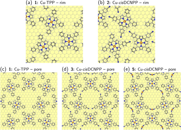
Atomic structure of the triangular contact at the rim, (a) without and (b) with terminal CN groups. (c) Open pore structure, (d) with terminal CN groups interacting with neighboring Cu atoms of the substrate, and (e) with terminal CN groups connected by Cu adatoms.
By comparing the binding energy per molecule of this structure with the value for the single, well‐separated molecule we can determine the strength of the molecule‐molecule interaction for the rim contact. Since no “pore interaction” is present, is given by the difference of the two binding energies. The rim interaction is attractive with about 0.11 eV per molecule (see Table 1). Since we do not observe that the Cu‐TPP molecules are pulled out of their bridge position, the dispersion interaction across the rim is close to its optimum and cannot be increased further by bringing the Cu‐TPP molecules closer together.
Table 1.
Calculated binding energy per molecule of Cu porphyrins on Cu(111) for the 6 porous honeycomb‐type structures discussed in the text. All calculations were done with a (7√3×7√3)R30° unit cell containing three porphyrin molecules. is the binding energy of a single, well‐separated porphyrin molecule as given in Table S1. The difference ΔE b between the two binding energies describes the on‐surface molecule‐molecule interaction.
|
Porphyrin |
|
|
ΔE b [eV] |
||
|---|---|---|---|---|---|
|
1: Cu‐TPP |
3.50 |
3.39 |
+0.11 |
||
|
2: Cu‐cisDCNPP |
3.61 |
3.60 |
+0.01 |
||
|
3: Cu‐cisDCNPP |
3.68 |
3.60 |
+0.08 |
||
|
4: Cu‐TCNPP |
3.67 |
3.79 |
−0.12 |
||
|
5: Cu‐cisDCNPP+Cuad |
4.06 |
3.44 |
+0.62 |
||
|
6: Cu‐TCNPP+Cuad |
4.17 |
3.69 |
+0.48 |
The next three structures 2–4 were obtained by adding CN groups to structure 1 (see Figure S9). Structure 2 consists of Cu‐cisDCNPPs with CN groups in the rim area while still maintaining an “open” pore (see Figure 7 b). The N atoms of the terminal CN groups coordinate to surface Cu atoms as in the case of well‐separated adsorbates (see Figure 6 b) and do not establish hydrogen bonds with the neighboring pyrrole rings. The lower‐lying CN groups basically do not interact with the higher‐lying pyrrole rings of the neighboring molecules. Consequently, the binding energy per molecule in the network structure is basically unchanged compared to the isolated adsorbate (i.e. is almost zero, see Table 1). This shows that the same packing of “pore triangles” can be achieved with and without CN groups at the outer rim.
Structure 3 is also built of Cu‐cisDCNPPs, but now the CN groups are pointing to the pore (see Figure 7 d and Figure S9). These CN groups connect to neighboring Cu atoms on the Cu(111) surface. In previous studies, it was speculated that such an adsorption on neighboring sites could lead to an attractive interaction induced by a small lift of the Cu atoms out of the surface plane.31 However, in our previous calculations12b we could not confirm the presence of an attractive interaction but found a small repulsion instead. Also here, the inspection of the binding energies points toward the absence of a significant attractive interaction between neighboring CN‐Cu sites. Structure 3 exhibits the same rim contact as structure 1 together with a pore contact consisting of terminal CN groups interacting with neighboring substrate Cu sites. The rim contact should give at least the same gain in binding energy ΔE b of 0.11 eV as observed in structure 1. However, for structure 3 we only observe a gain of 0.08 eV (see Table 1). The difference of 0.03 eV per Cu‐cisDCNPP molecule stems from the pore interaction and is repulsive.
The absence of a significant attractive interaction of CN−Cu contacts involving neighboring Cu surface sites is furthermore demonstrated by repeating the calculations of the structural motif 3 with a larger (8√3×8√3)R30° unit cell, in which we can systematically open and close the pore and the rim contact (see Figure S10). No significant change in energy is observed when the CN−Cu sites are pulled apart by one Cu−Cu distance.
Also structure 4 (Figure S9 d) of the porphyrins with four terminal CN groups (Cu‐TCNPP) indicates a repulsive interaction for the pore contact. The binding energy per molecule is reduced with respect to the separated molecules. In the first place, the rim contact has become slightly repulsive since the porphyrins cannot be displaced anymore from their bridge sites (compare to structure 2 in Figure 7 b and d), but obviously this is not compensated by a strong attractive pore interaction.
In summary, in the triangular pore motif, a strong repulsion between facing CN groups of neighboring porphyrin molecules is avoided by a bending‐down of the CN groups and the formation of CN−Cu contacts with neighboring Cu surface atoms. However, this binding motif does not lead to a significant attractive interaction between the porphyrins. The experimentally observed dominant formation of the triangular pore structure and its thermal stability therefore cannot be explained by this binding motif.
On the other hand, Cu adatoms can mediate a strong attraction. If Cu adatoms are added to structure 3 (the result is structure 5, see Figure 7 e and Figure S11), the binding energy per molecule increases by 0.65 eV compared to separated molecules (see Table 1). Subtracting the contribution of the rim contact of 0.11 eV (see structure 1), we find a strong attractive pore interaction of 0.54 eV per molecule. The origin of the attraction is that now two instead of only one CN group connect to a Cu adatom (or, in other words, less Cu adatoms for a given number of CN groups have to be created). The strong attractive pore interaction is also confirmed by adding Cu adatoms to structure 4 (giving structure 6; see Figure 3 b), where we find a value of 0.48 eV for the molecule‐molecule interaction in the pore (assuming that the rim interaction is about zero, see structure 2).
The overall larger binding energy for the network structures with Cu adatoms also implies that they are the thermodynamic ground state. This is in contrast to single molecules, where the DFT calculations predict a decomposition of adatom structures into molecules adsorbed on the terrace and a condensation of the Cu atoms at zero temperature (see Supporting Information).
Conclusions
We investigated the adsorption of three related cyano‐functionalized tetraphenyl porphyrin derivatives on Cu(111) by scanning tunneling microscopy (STM) in ultra‐high vacuum (UHV) combined with detailed density functional theory (DFT) calculations. The goal was to identify the role of the cyano group and the central Cu atom for the intermolecular and supramolecular arrangement. The porphyrin derivatives studied were Cu‐TCNPP, Cu‐cisDCNPP, and 2H‐cisDCNPP. Cu‐TCNPP, with four cyano groups, forms a hexagonal honeycomb‐type pattern with triangular pores, which coexists with 1D molecular double chains at room temperature (RT). Annealing to 400 K yields a complete transformation to a hexagonal honeycomb‐type structure with pronounced long‐range order. Cu‐cisDCNPP, with two cyano groups in “cis” position, forms monoflakes with a triangular pore, along with bi‐ and multiflakes at RT, which all transform to the hexagonal honeycomb‐type structure at 400 K. The metal‐free 2H‐cisDCNPP shows no order at RT, but self‐metalates upon heating to 400 K and transforms into the same perfectly ordered hexagonal honeycomb‐type structure as the other two porphyrins. The ordered flakes and the hexagonal honeycomb‐type structures all contain the same structure‐forming element, namely triangles of porphyrins fused together by cyano‐Cu‐cyano interactions with native Cu adatoms. These three molecules are rotated to each other by 60° and are aligned parallel to the substrate high‐symmetry directions; this alignment is enforced by the preferential adsorption arrangement of the porphyrins and it is stabilized by the linking Cu adatoms at threefold sites at the corners of the pores. These site‐specific interactions with the Cu surface also make the long‐range ordered structure commensurate. The DFT calculations provide detailed insights into the various energetic contributions that lead to the observed long‐range ordered hexagonal honeycomb‐type structure with triangular pores. Looking at the internal structure of the unit cell, one gets the impression that interactions of the other two porphyrin ligands (with CN groups for Cu‐TCNPP, and without CN ligands for Cu‐cisDCNPP and 2H‐cisDCNPP) do not play a major role for the formation of the long‐range order. This finding leads us to suggest that the twofold cyano‐functionalized porphyrin with “cis” conformation is the minimum prerequisite to form a highly ordered 2D porous molecular pattern that might grant protocols as a nanoscaled template. To conclude, our findings suggest that the cyano groups as functional groups participate in directed attractive interactions, which will allow for the rational design and construction of a wide range of nano‐scaled supramolecular architectures adsorbed to surfaces.
Conflict of interest
The authors declare no conflict of interest.
Supporting information
As a service to our authors and readers, this journal provides supporting information supplied by the authors. Such materials are peer reviewed and may be re‐organized for online delivery, but are not copy‐edited or typeset. Technical support issues arising from supporting information (other than missing files) should be addressed to the authors.
Supplementary
Acknowledgements
The authors gratefully acknowledge funding by the German Research Foundation (DFG) through Research Unit FOR 1878 (funCOS) and the Collaborative Research Center SFB 953 (project number 182849149) at the Friedrich‐Alexander‐Universität Erlangen‐Nürnberg. Open access funding enabled and organized by Projekt DEAL.
R. Adhikari, G. Siglreithmaier, M. Gurrath, M. Meusel, J. Kuliga, M. Lepper, H. Hölzel, N. Jux, B. Meyer, H.-P. Steinrück, H. Marbach, Chem. Eur. J. 2020, 26, 13408.
Contributor Information
Prof. Dr. Bernd Meyer, Email: bernd.meyer@fau.de.
Prof. Dr. Hans‐Peter Steinrück, Email: hans-peter.steinrueck@fau.de.
References
- 1. Anderson S., Anderson H. L., Bashall A., McPartlin M., Sanders J. K., Angew. Chem. Int. Ed. 1995, 34, 1096–1099; [Google Scholar]; Angew. Chem. 1995, 107, 1196–1200. [Google Scholar]
- 2.
- 2a. Barth J. V., Weckesser J., Cai C., Günter P., Bürgi L., Jeandupeux O., Kern K., Angew. Chem. Int. Ed. 2000, 39, 1230–1234; [DOI] [PubMed] [Google Scholar]; Angew. Chem. 2000, 112, 1285–1288; [Google Scholar]
- 2b. Llanes-Pallas A., Matena M., Jung T., Prato M., Stöhr M., Bonifazi D., Angew. Chem. Int. Ed. 2008, 47, 7726–7730; [DOI] [PubMed] [Google Scholar]; Angew. Chem. 2008, 120, 7840–7844; [Google Scholar]
- 2c. Theobald J. A., Oxtoby N. S., Phillips M. A., Champness N. R., Beton P. H., Nature 2003, 424, 1029. [DOI] [PubMed] [Google Scholar]
- 3. Beniwal S., Chen S., Kunkel D., Hooper J., Simpson S., Zurek E., Zeng X. C., Enders A., Chem. Commun. 2014, 50, 8659–8662. [DOI] [PubMed] [Google Scholar]
- 4. Yokoyama T., Yokoyama S., Kamikado T., Okuno Y., Mashiko S., Nature 2001, 413, 619. [DOI] [PubMed] [Google Scholar]
- 5. Barth J. V., Surf. Sci. 2009, 603, 1533–1541. [Google Scholar]
- 6.
- 6a. Auwärter W., Seufert K., Bischoff F., Ecija D., Vijayaraghavan S., Joshi S., Klappenberger F., Samudrala N., Barth J. V., Nat. Nanotechnol. 2012, 7, 41; [DOI] [PubMed] [Google Scholar]
- 6b. Wiengarten A., Lloyd J. A., Seufert K., Reichert J., Auwärter W., Han R., Duncan D. A., Allegretti F., Fischer S., Oh S. C., Chem. Eur. J. 2015, 21, 12285–12290. [DOI] [PubMed] [Google Scholar]
- 7. Zhang L., Lepper M., Stark M., Menzel T., Lungerich D., Jux N., Hieringer W., Steinrueck H.-P., Marbach H., Phys. Chem. Chem. Phys. 2017, 19, 20281–20289. [DOI] [PubMed] [Google Scholar]
- 8. Auwärter W., Écija D., Klappenberger F., Barth J. V., Nat. Chem. 2015, 7, 105. [DOI] [PubMed] [Google Scholar]
- 9. Fleming I., Nature 1967, 216, 151. [Google Scholar]
- 10. Castro C. E., J. Theor. Biol. 1971, 33, 475–490. [DOI] [PubMed] [Google Scholar]
- 11.
- 11a. Xiao J., Ditze S., Chen M., Buchner F., Stark M., Drost M., Steinrück H.-P., Gottfried J. M., Marbach H., J. Phys. Chem. C 2012, 116, 12275–12282; [Google Scholar]
- 11b. Ditze S., Stark M., Drost M., Buchner F., Steinrück H. P., Marbach H., Angew. Chem. Int. Ed. 2012, 51, 10898–10901; [DOI] [PubMed] [Google Scholar]; Angew. Chem. 2012, 124, 11056–11059; [Google Scholar]
- 11c. Stark M., Ditze S., Drost M., Buchner F., Steinrück H.-P., Marbach H., Langmuir 2013, 29, 4104–4110; [DOI] [PubMed] [Google Scholar]
- 11d. Röckert M., Ditze S., Stark M., Xiao J., Steinrück H.-P., Marbach H., Lytken O., J. Phys. Chem. C 2014, 118, 1661–1667; [DOI] [PubMed] [Google Scholar]
- 11e. Marbach H., Acc. Chem Res. 2015, 48, 2649–2658. [DOI] [PubMed] [Google Scholar]
- 12.
- 12a. Lepper M., Köbl J., Zhang L., Meusel M., Hölzel H., Lungerich D., Jux N., de Siervo A., Meyer B., Steinrück H. P., Angew. Chem. Int. Ed. 2018, 57, 10074–10079; [DOI] [PubMed] [Google Scholar]; Angew. Chem. 2018, 130, 10230–10236; [Google Scholar]
- 12b. Lepper M., Schmitt T., Gurrath M., Raschmann M., Zhang L., Stark M., Hölzel H., Jux N., Meyer B., Schneider M. A., J. Phys. Chem. C 2017, 121, 26361–26371; [Google Scholar]
- 12c. Reichert J., Marschall M., Seufert K., Ecija D., Auwärter W., Arras E., Klyatskaya S., Ruben M., Barth J. V., J. Phys. Chem. C 2013, 117, 12858–12863; [Google Scholar]
- 12d. Fendt L. A., Stöhr M., Wintjes N., Enache M., Jung T. A., Diederich F., Chem. Eur. J. 2009, 15, 11139–11150; [DOI] [PubMed] [Google Scholar]
- 12e. Stöhr M., Boz S., Schär M., Nguyen M. T., Pignedoli C. A., Passerone D., Schweizer W. B., Thilgen C., Jung T. A., Diederich F., Angew. Chem. Int. Ed. 2011, 50, 9982–9986; [DOI] [PubMed] [Google Scholar]; Angew. Chem. 2011, 123, 10158–10162. [Google Scholar]
- 13.
- 13a. Fan Q., Wang C., Liu L., Han Y., Zhao J., Zhu J., Kuttner J., Hilt G., Gottfried J. M., J. Phys. Chem. C 2014, 118, 13018–13025; [Google Scholar]
- 13b. Steiner C., Yang Z., Gliemann B. D., Meinhardt U., Gurrath M., Ammon M., Meyer B., Kivala M., Maier S., Chem. Commun. 2018, 54, 11554–11557; [DOI] [PubMed] [Google Scholar]
- 13c. Tao Z., Wang T., Wu D., Feng L., Huang J., Wu X., Zhu J., Chem. Commun. 2018, 54, 7010–7013. [DOI] [PubMed] [Google Scholar]
- 14. Piot L., Bonifazi D., Samori P., Adv. Funct. Mater. 2007, 17, 3689–3693. [Google Scholar]
- 15. Lackinger M., Heckl W. M., Langmuir 2009, 25, 11307–11321. [DOI] [PubMed] [Google Scholar]
- 16. Iancu V., Braun K.-F., Schouteden K., Van Haesendonck C., Langmuir 2013, 29, 11593–11599. [DOI] [PubMed] [Google Scholar]
- 17. Gottardi S., Müller K., Moreno-López J. C., Yildirim H., Meinhardt U., Kivala M., Kara A., Stöhr M., Adv. Mater. Interfaces 2014, 1, 1300025. [Google Scholar]
- 18. Klein B. P., Morbec J. M., Franke M., Greulich K. K., Sachs M., Parhizkar S., Bocquet F. C., Schmid M., Hall S. J., Maurer R. J., Meyer B., Tonner R., Kumpf C., Kratzer P., Gottfried J. M., J. Phys. Chem. C 2019, 123, 29219–29230. [Google Scholar]
- 19. Kachel S. R., Klein B. P., Morbec J. M., Schöniger M., Hutter M., Schmid M., Kratzer P., Meyer B., Tonner R., Gottfried J. M., J. Phys. Chem. C 2020, 124, 8257–8268. [Google Scholar]
- 20.
- 20a. Weber-Bargioni A., Auwärter W., Klappenberger F., Reichert J., Lefrancois S., Strunskus T., Wöll C., Schiffrin A., Pennec Y., Barth J. V., ChemPhysChem 2008, 9, 89–94; [DOI] [PubMed] [Google Scholar]
- 20b. Brede J., Linares M., Kuck S., Schwöbel J., Scarfato A., Chang S.-H., Hoffmann G., Wiesendanger R., Lensen R., Kouwer P. H., Nanotechnology 2009, 20, 275602. [DOI] [PubMed] [Google Scholar]
- 21.
- 21a. Albrecht F., Bischoff F., Auwärter W., Barth J. V., Repp J., Nano Lett. 2016, 16, 7703–7709; [DOI] [PubMed] [Google Scholar]
- 21b. Lepper M., Köbl J., Schmitt T., Gurrath M., de Siervo A., Schneider M. A., Steinrück H.-P., Meyer B., Marbach H., Hieringer W., Chem. Commun. 2017, 53, 8207–8210. [DOI] [PubMed] [Google Scholar]
- 22. Moreno-López J. C., Mowbray D. J., Perez Paz A., de Campos Ferreira R. C., Ceccatto dos Santos A., Ayala P., de Siervo A., Chem. Mater. 2019, 31, 3009–3017. [Google Scholar]
- 23.
- 23a. Lepper M., Zhang L., Stark M., Ditze S., Lungerich D., Jux N., Hieringer W., Steinrück H.-P., Marbach H., J. Phys. Chem. C 2015, 119, 19897–19905; [DOI] [PubMed] [Google Scholar]
- 23b. Grimme S., Angew. Chem. Int. Ed. 2008, 47, 3430–3434; [DOI] [PubMed] [Google Scholar]; Angew. Chem. 2008, 120, 3478–3483. [Google Scholar]
- 24. Henningsen N., Rurali R., Limbach C., Drost R., Pascual J., Franke K., J. Phys. Chem. Lett. 2011, 2, 55–61. [DOI] [PubMed] [Google Scholar]
- 25. Heim D., Ecija D., Seufert K., Auwärter W., Aurisicchio C., Fabbro C., Bonifazi D., Barth J. V., J. Am. Chem. Soc. 2010, 132, 6783–6790. [DOI] [PubMed] [Google Scholar]
- 26. Baker Cortés B. D., Schmidt N., Enache M., Stöhr M., J. Phys. Chem. C 2019, 123, 19681–19687. [DOI] [PMC free article] [PubMed] [Google Scholar]
- 27. Di Santo G., Blankenburg S., Castellarin-Cudia C., Fanetti M., Borghetti P., Sangaletti L., Floreano L., Verdini A., Magnano E., Bondino F., Chem. Eur. J. 2011, 17, 14354–14359. [DOI] [PubMed] [Google Scholar]
- 28. Röckert M., Franke M., Tariq Q., Ditze S., Stark M., Uffinger P., Wechsler D., Singh U., Xiao J., Marbach H., Chem. Eur. J. 2014, 20, 8948–8953. [DOI] [PubMed] [Google Scholar]
- 29. Ceccatto dos Santos A., de Campos Ferreira R. C., Moreno-López J. C., Barreto L., Lepper M., Landers R., Steinrück H.-P., Marbach H., de Siervo A., Chem. Mater. 2020, 32, 2114–2122. [Google Scholar]
- 30. Stark M., Ditze S., Lepper M., Zhang L., Schlott H., Buchner F., Röckert M., Chen M., Lytken O., Steinrück H.-P., Chem. Commun. 2014, 50, 10225–10228. [DOI] [PubMed] [Google Scholar]
- 31. Tseng T.-C., Urban C., Wang Y., Otero R., Tait S. L., Alcamí M., Écija D., Trelka M., Gallego J. M., Lin N., Nat. Chem. 2010, 2, 374–379. [DOI] [PubMed] [Google Scholar]
Associated Data
This section collects any data citations, data availability statements, or supplementary materials included in this article.
Supplementary Materials
As a service to our authors and readers, this journal provides supporting information supplied by the authors. Such materials are peer reviewed and may be re‐organized for online delivery, but are not copy‐edited or typeset. Technical support issues arising from supporting information (other than missing files) should be addressed to the authors.
Supplementary