

Abstract
Dynamical systems that evolve unidirectionally with respect to time provide a natural mechanism for implementing a time-domain, near-zero-threshold energy rectifier. In this paper we implement such a dynamical system using a pair of differential, leaky floating-gates and demonstrate that the circuit can sense and record signals of interest while compensating for environmental variations. A Fowler-Nordheim (FN) tunneling current has been used to implement the leakage process, which we experimentally show can be modulated by signals at energy levels below femtojoules. At this level of energy, the proposed FN-system could be self-powered using different types of biopotential energy sources like intra-cellular potentials, a feature that was not possible with previously reported recorders. Furthermore, the degree of modulation is shown to be a function of the input intensity as well as time-of-occurrence, which opens up the possibility of using reconstruction techniques to reconstruct the input signal from measurement of multiple sensing devices. Using devices fabricated in a 0.5 μm standard CMOS process, we demonstrate recording of 6 mV events with retention capability lasting over 30 minutes.
I. Introduction
Self-powered sensors harvest their operational energy directly from the signal being sensed [1], As a result, these type of sensors are attractive for long-term and autonomous monitoring applications [2] where the use of batteries or remote powering is considered to be impractical. All implementations of self-powered sensors require some form of rectification and therefore its sensitivity is typically limited by the threshold of the rectifying element. For instance, the self-powered sensor that was reported in [3] and used for monitoring biomechanical activity was shown to be limited by the minimum 4.2V activation voltage required to initiate hot-electron injection. For other self-powered sensor/systems the diode threshold or the transistor operational limits determines the system sensitivity, and the state-of-the-art implementations can only self-power at voltage-levels above 35 mV ([4]–[6]). A novel approach to reduce this energy/voltage threshold is to implement the rectification operation in time-domain using a dynamical system that unidirectionally evolves with respect to time. For example, leakage of charge stored in a capacitor is a dynamical process that thermodynamically evolves in one direction with respect to time and without any need for external powering. This leakage process can be easily modulated by coupling an external signal (through a coupling capacitor) of arbitrarily small magnitude.
However, the challenge in implementing such a dynamical system on silicon is to achieve long-term operation (process evolving over duration of a few years) and reliability/robustness to fabrication and noise artifacts. Such a dynamical system was first reported in [7] and since then has been used for numerous time-keeping applications including time-stamping of sensing events [8]. In this paper, we configure this time-keeping device as a differential self-powered sensor that is robust against environmental variations and can be used to detect/record signals down to 6mV. As a result, the proposed sensor can self-power itself using biopotentials recorded using standard electrodes, as shown in Fig. 1. The long-term statistics recorded by the sensor could then be retrieved using a read-out module that can be asynchronously powered. This “sense-now retrieve-later” operating paradigm has been extensively used in other types of self-powered sensors as well [9].
Fig. 1. Sense now, retrieve later paradigm:
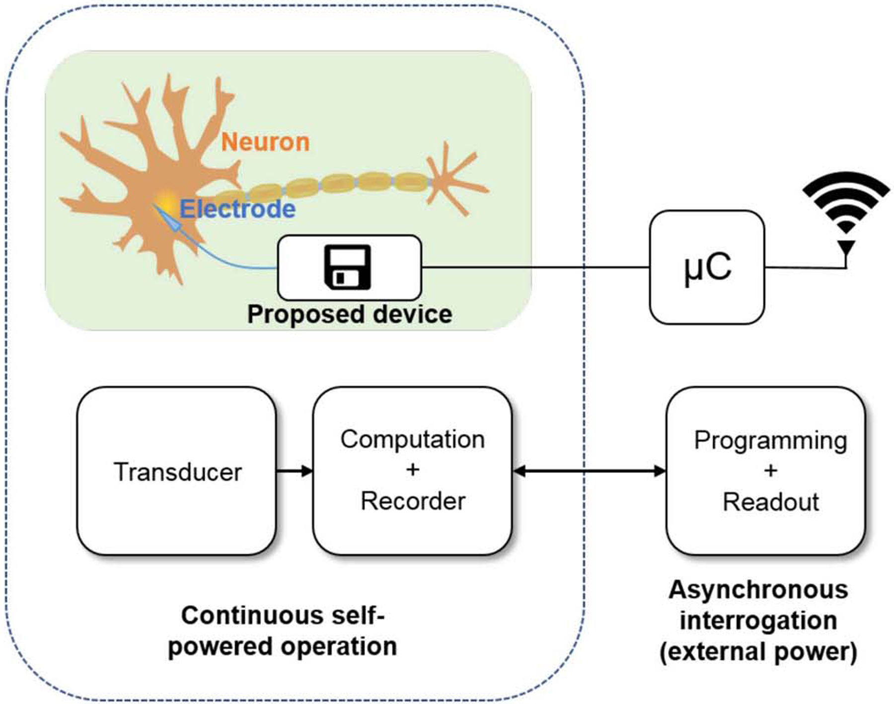
Signal is sensed and recorded using energy from the signal; which is retrieved later asynchronously through conventional means like RF or ultrasound. Neural recording as a target application for the proposed device is shown.
II. Principle of operation
At the core of the proposed dynamical system is leakage process that is driven by FN tunneling of electrons through a triangular gate-oxide barrier, as shown in Fig. 2a. The equivalent circuit model of this system is shown in Fig. 2b using a voltage-dependent current density JFN(Vfg) that discharges the capacitor Cfg. FN tunneling current density (J) across a triangular barrier can be expressed as a function of the electric field (E) across the barrier [10]:
| (1) |
where α and β are device parameters.
Fig. 2.
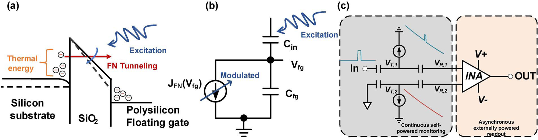
a) Dynamical system based on FN tunneling of electrons. Excitation signal changes the barrier shape and modulates the rate of tunneling. b) Equivalent circuit model of the proposed sensor. c) Differential implementation to compensate for environmental variations.
To use this device as a sensor, a coupling capacitor is added to the system (Cin, as shown in Fig. 2b), that allows the input signal to modulate the electric field and thus the tunneling current. The modulated electric field for an input signal with potential X(t) can now be estimated as:
| (2) |
where EFG is the field due to charge on the floating gate, tox is the oxide thickness and c is the coupling ratio due to capacitive divider formed by Cin and Cfg. For an arbitrary input signal, the above equation is not tractable. For the special case where there is no external signal, it can be analytically solved and floating gate voltage can be expressed as a function of time (t):
| (3) |
where k0, k1 k2 are model parameters estimated from the device form factors and Vsub is the equivalent voltage drop at the substrate of the device. As VFG(t) is a function of only time, this model can be exploited for self-powered time keeping as reported in [7]. In contrast, here we look at the deviation from the modeled response to detect events in the input signal history.
In [11], it was shown that a 1V modulation signal can change the modeled timer response by 10 mV. However, many signals of interest might be much smaller and the change in timer response would be on the order of microvolts. However the timer response is susceptible to environmental variations, like temperature and there can be a an error on the order of 1% (or few millivolts over a period of days) in timer response because of environmental factors [7]. In such cases, microvolt responses would be impossible to recover. To compensate for these noises, we designed a differential architecture (Fig. 2c), by introducing another timer, the input of which is connected to a reference or ground. The first timer acts as a sensing and storage element, while the second timer (matched to the first) acts as a reference. Both timers are initially synchronized such that their discharge rates are equal. During the presence of a signal, sensing timer’s operating point is shifted; it’s discharge rate changes and it becomes desynchronized with the reference timer. A measurement made before the timers resynchronize, will contain information about the sensor signal.
III. Circuit Implementation
A top level schematic of the timer-based sensor circuit is shown in 3. The sensor and reference branches have identical circuits. In each branch, there is a floating gate node with FN tunneling junction. The floating gate accepts input through an input capacitor (2.5 pF), which is connected to the signal source in the sensor branch or to ground in the reference branch. This node is decoupled from the readout interface by a decoupling capacitor (CD). Primary reason for doing this was that the tunneling node acts in the region of 7.5 – 8.5V, and reading out these higher voltages would have introduced a possibility of charge injection into the floating gate node. The floating gate programming module controls the charge on each floating gate node independently through tunneling (coarse) and hot electron injection (fine) mechanisms. Finally, a source follower buffers the readout voltage to a digital multimeter.
Above circuit was implemented on 0.5μ CMOS process (micrograph of chip shown in Fig. 3a) through MOSIS Education Program. The floating gates were created on PMOS transistors. The FN tunneling junctions of the two branches were interdigitated and they shared the same substrate to ensure they were exposed to similar micro-environments. An instrumentation amplifier was also fabricated; however results from the amplifier are not reported here. Instead, raw voltages at the readout nodes (VR,1 and VR,2) are buffered and measured.
Fig. 3.
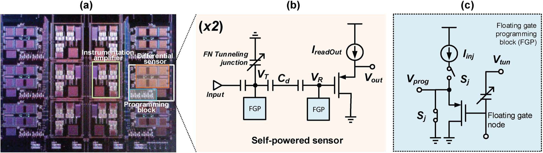
a) Micrograph of the timer array integrating 6 pairs of differential timers and instrumentation amplifiers. Each timer pair occupies 310×245 μm2 b) Schematic of the EN-timer based sensor circuit c) Floating gate programming block
IV. Results
In a real-world deployment, programming of floating gate nodes and the asynchronous retrieval of sensor outputs would be done using an external power source, while the actual operation would be completely self-powered. Since our goal here is to demonstrate the sensing and storage of signals, the system was continuously powered. For each run, tunneling voltage of 21V was applied to bias the timers in the region of 9V, and were then allowed to discharge. Timer responses were continuously measured, and an initial synchronization point was estimated where two timers had the same discharge rate. The timers were programmed to this point by applying an external DC signal. This was considered to be the starting point of the experiment. A square pulse with variable magnitude (0 – 20 mV) and duration = 120 seconds was set to occur 30 minutes after the start of the experiment. In a second set of experiments the magnitude was fixed to 20 mV while the time of occurrence was varied from 10 minutes to 40 minutes.
A. Synchronization of matched timers
Though the response of a timer can be modeled accurately, it experiences errors in time keeping due to environmental factors like temperature variation. In [7], 1% modeling and time keeping accuracy was reported. We observed similar results in our set of experiments (Fig. 4a). We compared the reference timer’s output over 5 trials of 1500 seconds. It was initialized to the same starting point and it experienced a voltage drop of 20mV over a period of the experiment. There was a deviation of 200μV from the mean response. It was also observed that the deviation had a monotonic trend that tended to increase with time. In contrast, the matched timers (Fig. 4b) were more synchronized. The reference and sensing timers had similar drifts, and thus their deviations from baseline were compensated. In our experiment, the difference between their voltage changes (ΔVz) were bounded to 50μV (< 0.25%)for the same time period. Also there was no discernible drift in the difference.
Fig. 4.
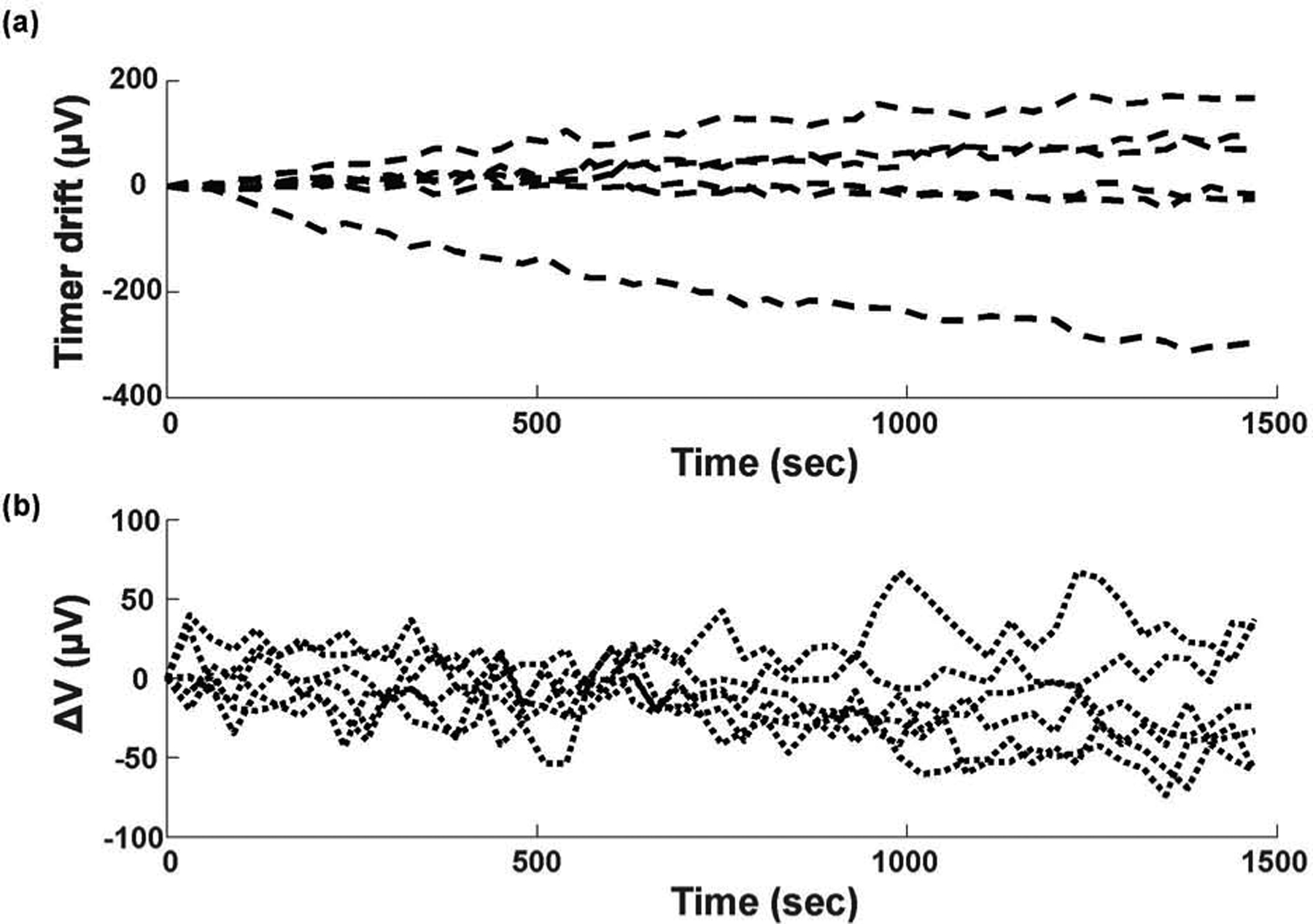
a) Deviation of a single timer response for each of the five trials from the mean response of the five trials b) Difference between responses of the two matched timers for five trials. Note that the matched pairs are more synchronized.
B. Timer as a sensor
This section describes the behavior of the self-powered sensor when a single square pulse is applied to the sensing timer. As previously described, the timers were initialized so that they have the same discharge rates. After 30 min, a pulse of 20 mV was applied for 120 seconds (Fig. 5a). Because of the capacitive divider formed by the input capacitor, decoupling capacitor and parasitic capacitances, 9.3 mV signal is seen at the readout node. The input signal causes the timing node’s rate of FN tunneling to increase, according to eqn. 1. If the difference between timers’ change from the initial point is calculated, the effect of the modulation is clearly visible. After the pulse, a 155μV deviation in ΔVz was observed. The effect lasted for the remainder of the experiment, which implies that the sensor retained memory of the event for at least 30 minutes. This memory is semi-volatile as the sensor tries to resynchronize. But since ΔVz is small, its effect on the tunneling rate is smaller compared to the modulation signal of 20 mV. How long does the memory last and at what resolution needs to be studied in greater detail.
Fig. 5.
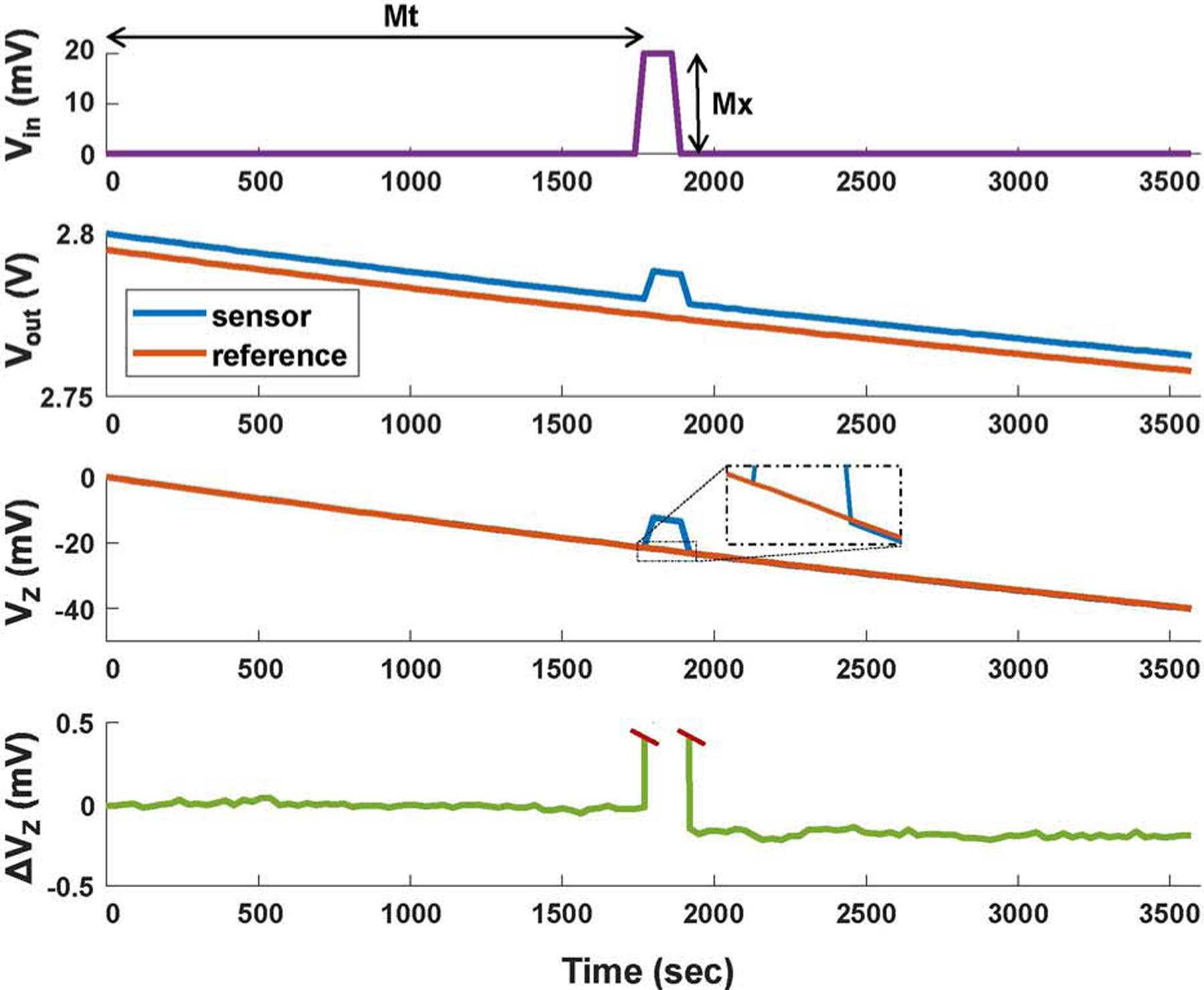
Demonstration of the principle of operation. a)Input signal - square pulse with magnitude Mx occurring at time Mt b) Raw output from the two branches c) Change from the starting point obtained by subtracting the initial value from the raw output of (b) d) Difference between the two outputs
C. Sensitivity of the self-powered sensor
In this set of experiments, we looked at how small a signal can our system sense and how does the response change with varying signal strength. We conducted multiple experiments according to protocol described in previous section. We varied the modulation voltage (Mx) from 0 mV to 20 mV in steps of 2 mV and three trials were carried out for each run. Though the system did not show a robust response for 2 mV and 4 mV signals, there was a significant response for the 6 mV signal (Fig. 6a).
Fig 6.

a) Effect of modulation magnitude (Mx) on sensor response b) Effect of time of occurrence of modulation signal (Mt) on sensor response
These experiments do not indicate the absolute sensitivity of timer-based sensing approach, as the sensitivity can be altered by changing device parameters (capacitance, tunneling junction area, oxide thickness etc) or even by varying the operating point of the same device. If the timer is biased in high tunneling region, its sensitivity will be higher, which drops as time elapses. Finally the noise performance of readout circuits and measurement instruments limit the sensitivity of the system. The energy required in charging and discharging the equivalent input capacitance of 1 pF by 6 mV is on the order of 10−17W, which can be provided by most signals that are being measured. Thus such a system has the potential of being deployed without any external power source for a wide range of applications. Though the sensor’s response is inherently non-linear, a linear model could be fit to the sensor with reasonable accuracy (R2 = 0.87) at the low modulation levels studied here.
D. Temporal dependence
We are proposing to utilize the self-powered sensor in a sense-now retrieve-later approach to sensing; wherein the system is monitoring continuously without external power source and measurements are made asynchronously. The previous section showed that if the timer response is deviated from its baseline, we can estimate whether an event occurred and its intensity; but not when the event occurred. An event can be time-stamped only if the system’s response is a function of time. As the timer dynamics are non-linear in the time domain, it is expected that the modulation response would be a function of time. To test out this hypothesis, we subjected the sensor to the same event at different time instances and measured the response (Fig. 6b). As can be seen, the same event leads to a lower response if it occurs at a later instance. This phenomenon can be exploited for time stamping of signal history. As an example, two timers with different functions can be used to estimate the intensity and time of occurrence of a single event.
V. Conclusion
In this paper, we have described a system that can sense and record signals using tens of attowatts of power through modulation of dynamical processes. The system’s response depends on the intensity of the event and its time of occurrence. The system also exhibits memory effects at these ultra low power levels. Here, the sensor was subjected to a single event. Reconstructing a signal with two or more events, is an ill-posed problem. Using responses from multiple sensors and state-of-the-art reconstruction techniques, it may be possible to infer salient events in the signal history. More research needs to be done in this area.
Acknowledgment
This work was supported by National Eye Institute, NIH (Project: 1R21EY028362-01)
Contributor Information
Barani Raman, Biomedical Engineering, Washington University in St. Louis, St. Louis, MO 63112, USA.
Shantanu Chakrabartty, Electrical and Systems Engineering, Washington University in St. Louis, St. Louis, MO 63112, USA.
References
- [1].Wang ZL, “Toward self-powered sensor networks,” Nano Today, vol. 5, no. 6, pp. 512–514, 2010. [Google Scholar]
- [2].Aono K, Lajnef N, Faridazar F, and Chakrabartty S, “Infrastructural health monitoring using self-powered internet-of-things,” in Circuits and Systems (ISCAS), 2016 IEEE International Symposium on, pp. 2058–2061, IEEE, 2016. [Google Scholar]
- [3].Zhou L, Abraham AC, Tang SY, and Chakrabartty S, “A 5 nw quasi-linear cmos hot-electron injector for self-powered monitoring of biomechanical strain variations,” IEEE transactions on biomedical circuits and systems, vol. 10, no. 6, pp. 1143–1151, 2016. [DOI] [PMC free article] [PubMed] [Google Scholar]
- [4].Ramadass YK and Chandrakasan AP, “A battery-less thermoelectric energy harvesting interface circuit with 35 mv startup voltage,” IEEE Journal of Solid-State Circuits, vol. 46, no. 1, pp. 333–341, 2011. [Google Scholar]
- [5].Instruments T, “bq25505.” http://www.ti.com/lit/ds/symlink/bq25505.pdf, 2018.
- [6].Mercier PP, Lysaght AC, Bandyopadhyay S, Chandrakasan AP, and Stankovic KM, “Energy extraction from the biologic battery in the inner ear,” Nature biotechnology, vol. 30, no. 12, p. 1240, 2012. [DOI] [PMC free article] [PubMed] [Google Scholar]
- [7].Zhou L and Chakrabartty S, “Self-powered timekeeping and synchronization using fowler–nordheim tunneling-based floating-gate integrators,” IEEE Transactions on Electron Devices, vol. 64, no. 3, pp. 1254–1260, 2017. [Google Scholar]
- [8].Zhou L, Aono K, and Chakrabartty S, “A cmos timer-injector integrated circuit for self-powered sensing of time-of-occurrence,” IEEE Journal of Solid-State Circuits, 2018. [Google Scholar]
- [9].Sarkar P, Huang C, and Chakrabartty S, “An ultra-linear piezo-floating-gate strain-gauge for self-powered measurement of quasi-static-strain.,” IEEE Trans. Biomed. Circuits and Systems, vol. 7, no. 4, pp. 437–150, 2013. [DOI] [PubMed] [Google Scholar]
- [10].Lenzlinger M and Snow E, “Fowler-nordheim tunneling into thermally grown sio2” Journal of Applied physics, vol. 40, no. 1, pp. 278–283, 1969. [Google Scholar]
- [11].Zhou L and Chakrabartty S, “Self-powered sensing and time-stamping of rare events using cmos fowler-nordheim tunneling timers,” in Circuits and Systems (ISCAS), 2016 IEEE International Symposium on, pp. 2839–2842, IEEE, 2016. [Google Scholar]