

Abstract
Background Bridge plating for distal radius fractures is indicated for complex fractures with comminution, extensive articular involvement, and/or cases requiring immediate weight bearing. Bridge plate fixation of distal radius fractures is a well-documented treatment method; however, failures have been reported with repetitive loading through the bridged distal radius fracture. Plate design is implicated as a cause of plate fracture in select clinical studies but few mechanical tests comparing bridge plate designs have been reported. This study sought to determine the impact of plate design on bridge plates intended to allow for immediate weight-bearing.
Methods Axial static ( n = 3) and dynamic testing ( n = 3) was performed on three distraction plates designs: bridge plate 1 (BP1) with central holes, bridge plate 2 (BP2) without central holes, and locking compression plate (BP3). Plates were loaded in axial compression with a simulated 10-mm fracture gap.
Results Significant static load differences were noted between all groups. Static load to failure for BP1, BP3, and BP2 were 240 ± 5 N, 398 ± 9 N, and 420 ± 3 N, respectively ( p < 0.05). BP1 was the only plate series that failed during dynamic testing; all other plates achieved 100,000 cycles. Failure mode was a fracture occurring through the central screw hole of BP1. Finite element analysis demonstrated the effects of central screw holes on stress, strain, and plastic deformation under loading.
Conclusion Unused screw holes are the mechanical weak points; plates designed without these central screw holes are expected to survive greater load values. The threshold for clinical importance will need to be determined by future studies.
Keywords: bridge plating, distal radius fracture, mechanical testing, locking compression plate, trauma
Distal radius fractures are common types of fractures, with 640,000 cases reported every year in the United States. 1 These fractures affect all age groups, and may result from low-energy trauma caused by falling from a standing height to a high-energy trauma such as motor vehicle/sport accidents. 1 Bridge plates have been indicated for use in unstable or displaced fractures, fractures with extensive articular comminution, fractures with meta-diaphyseal comminution, and patients that require immediate weight-bearing with crutches or walkers through the fractured wrist. 2 3 4 5 The fixation strategy of bridge plating involves direct or indirect fracture reduction followed by stabilization with a wrist joint spanning “internal ex-fix” construct.
Locking compression plates (bridge plate 3 or BP3) are designed to treat any long bone fractures located on the tibia or femur but have been used to treat distal radius fractures. However, the thickness of the BP3 may result in soft tissue complications in the wrist such as rupture/adhesion of the extensor tendon, radial nerve damage, and postoperative digit stiffness. 6 These issues are addressed by modern bridge/distraction plates which are low profile, inserted using minimally invasive surgical approaches, and equipped with locking screws. 2 3 4 5
However, these commercially available distal radius bridge plates have been reported to result in plate fracture through unused medial screw holes, holes potentially used for supplemental lunate facet fixation, and with weight bearing ( Fig. 1 ). 5 7 Potential causes of plate failure include fatigue failure, narrow plate design, and stress risers from plate screw holes.
Fig. 1.

Radiograph of the distal radius in a patient who suffered a low-energy trauma and was treated with a dorsal spanning bridge plate. Failure was believed to have been caused by fatigue with a fracture through middle screw holes as seen through ( A ) anteroposterior and ( B ) lateral radiographs.
To better understand the potential causes of bridge plate failure and identify the difference in strength, mechanical testing was undertaken. The authors hypothesize that the central screw holes act as stress risers and removal of the central holes will increase the yield force value of the plate and thus allow for greater loads to be experienced before failure.
This study strove to answer the following questions:
What impact does bridge plate design have on static and dynamic testing yield force and fatigue results, and are there any significant differences?
How does axial loading affect the stress, strain, and plastic deformation profiles for various bridge plate designs?
Materials and Methods
Implant Materials
Three bridge plate designs were tested to investigate the differences in dynamic and static load-to-failure: (1) precontoured 11-hole, distal, proximal, and central (four at each distal/proximal end and three centrally) low-profile 2.8-mm thick locking dorsal spanning bridge plate (bridge plate 1 or BP1) (DePuy Synthes, Raynham, MA); (2) precontoured 8-hole, distal, and proximal (four holes at each distal/proximal end) low-profile 3-mm thick locking dorsal spanning bridge plate (bridge plate 2 or BP2) (ANTHEM, Globus Medical Inc., Audubon, PA); and (3) uniform 3.5-mm thick locking compression plate (BP3) (DePuy Synthes) ( Fig. 2 ). The locking screws used to fixate the implant to the polyethylene blocks, used for mounting each plate, had the following dimensions (numbered accordingly to the associated plate): 2.5 × 20 mm self-tapping locking screws (ANTHEM Bridge plate, Globus Medical Inc.) for BP2; 2.4 × 20 mm self-tapping locking screws (DePuy Synthes) for BP1; and 3.5 × 20 mm self-tapping locking screws (DePuy Synthes) for BP3.
Fig. 2.

Images of tested plates. ( A ) BP1, ( B ) BP3, and ( C ) BP2. BP1, bridge plate 1; BP2, bridge plate 2; BP3, bridge plate 3.
Test Setup
A total of 18 plates were used. Nine ( n = 3/group) of the plates were tested for static load-to-failure, and the other nine ( n = 3/group) were tested for dynamic load-to-failure. Screw holes were predrilled based on manufacturer's recommended drill bit diameters (1.8 mm for BP1 and BP2, and 2.8 mm for BP3) and through the recommended drill guides specific to each plate designs. Each plate was fixated with four 20-mm locking screws, proximally and distally, into a polyethylene cylinder, achieving eight total points of fixation per plate 2 8 ; with a 10-mm gap between polyethylene cylinder blocks to simulate an unstable distal radius fracture. The testing configuration was based on the external fixation test configuration, ASTM F1541 (02), with the necessary changes made to allow for testing of a bridge plate construct. The polyethylene blocks were connected to the load frame fixtures through axles, allowing the construct to freely rotate and bend during static and dynamic compression testing ( Fig. 3 ).
Fig. 3.

Test setup for static and dynamic failure testing.
A loading protocol was implemented to simulate immediate weight bearing, as experienced with crutches or a walker. Both static and dynamic load-to-failure were performed using an MTS 858 Bionix Servo-Hydraulic Axial Load Frame (MTS Systems Corporation, Eden Prairie, MN) with compression bending fixtures attached on both ends of the construct ( Fig. 3 ).
Static Compression
Each sample was loaded in compression in the manner mentioned above, at the rate of 5 mm/min until failure, defined as loss of resistance (decrease in the force reading measured in Newtons). 2
Dynamic Tension and Compression
Dynamic load-to-failure was defined as 90% of the 2-mm offset compressive static yield strength (90% = 217 N) of the weakest plate (BP1), with full force reversal in load-controlled tension/compression ( R = −1). Each plate experienced 100,000 cycles at 3 Hz or until failure occurred. Failure was defined as a 2- mm displacement beyond any deflection under loading. 2 The mode of failure for each plate was recorded.
Finite Element Analysis
In this study, finite element analysis (FEA) was performed to determine and visualize the effects of axial loading on the stress (internal forces being exerted on material), strain (deformation of the material), and plastic deformation (permanent deformation of material) between BP1 and BP2. The finite element simulations were developed to mimic the axial compression test performed in this study. The model setup was the same as the actual experimental one, with both bridge plates attached to two polyethylene cylinders using eight screws with the geometry of each component directly related to a CAD model. Materials evaluated included stainless-steel plates ( E = 196 GPa), cobalt chrome alloy screws ( E = 241 GPa), and polyethylene cylinders ( E = 672 MPa). The interaction between screw and plate were set as constrained surfaces, meaning that the plate and screws were not allowed to move relative to each other, which is valid in this case because locking screws were used to fixate both plates to the cylinders. The same constraints were applied to the screws and polyethylene cylinders due to the screw not pulling out in testing and seeming to have no pullout displacement. Both the top and bottom polyethylene cylinders were allowed to rotate along the hole axis, but the top cylinder was allowed to translate vertically as well.
Statistical Analysis
Statistical analysis was performed using IBM SPSS Statistics (SPSS v22, IBM Corp., Armonk, NY). Independent one-way ANOVA was performed to assess differences in outcome of plate strength during ultimate load and cyclic load to failure testing. Statistical significance was indicated at p < 0.05. Power analysis was performed using G*Power 3 (Release 3.1.9.2, University of Düsseldorf, Germany). 9
Results
How Does Bridge Plate Design Influence Immediate Postoperative and Long-Term Failure Characteristics?
The testing series consisted of three BP1, three BP2, and three BP3 for both static and dynamic testing conditions ( n = 3). Static yield values were calculated with a 2-mm offset (BP1: 241 ± 5 N; BP2: 420 ± 3 N; BP3: 397 ± 9 N). Significant differences were found between the three plate series ( p < 0.05), with BP2 significantly greater than BP3, and BP3 significantly greater than BP1 ( p < 0.001 for both BP3 and BP2 vs. BP1, and p = 0.032 for BP2 vs. BP3). For dynamic testing, all BP2 and BP3 plates reached 100,000 cycles and did not experience failure; however, all BP1 plates failed, with a fracture forming at the central screw hole. These fractures occurred in the same location for all of the BP1 plates, with an average cycle count to failure at 9,600 ± 2,300 cycles ( Fig. 4 ).
Fig. 4.
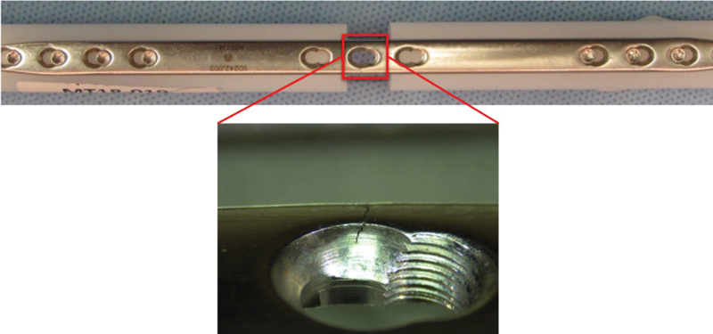
Failure mode ( crack ) located at the central hole in BP1 during dynamic testing at 7,700 cycles. BP1, bridge plate 1.
What Internal Loading Distribution Is Responsible for the Perceived Failure Characteristics?
Nonlinear FEA, was performed on BP1, BP2, and BP3 focusing on the effects of bridge plate design on stress, strain, and plastic deformation values during axial loading. As seen in Fig. 5 , stresses for all plates reached the tensile yield strength values (max values of 869 MPa in red) on the superior or inferior face of each plate. The max stress values permeated through the thinner portions (area around center screw holes) for BP1 while they occurred solely on the surface for BP2 and BP3. BP1 and BP3 also experienced greater levels of plastic deformation and strain (0.0456 for both deformation and strain), which were concentrated on the outer edges of the central screw hole, when compared with the values for BP2 (0.0083 and 0.0117, respectively) which demonstrated even distribution of both strain and plastic deformation across the plate surface as shown in Fig. 5 .
Fig. 5.

Stress ( top ), strain ( middle ), and plastic deformation ( bottom ) experienced by BP2, BP1, and BP3 ( from left to right ) during axial loading and displacement. BP1, bridge plate 1; BP2, bridge plate 2; BP3, bridge plate 3 or locking compression plate.
Discussion
The bridge plate concept for distal radius fractures began with nonlocking dynamic compression plating in neutral, spanned across the wrist dorsally using ligamentotaxis to stabilize the fracture to union. 10 Advantages of this technique were immediate fracture stabilization with restoration of length and alignment, indirect fracture reduction, the ability to span extensive articular or metaphyseal comminution, and the ability to allow immediate weight-bearing through the injured limb. However, the thickness of these dynamic compression plates, while adding strength to the implant, could be a source of irritation to the extensor tendons of the hand or iatrogenic fracture of the metacarpals. 6 Modern bridge plates aim to reduce soft tissue irritation by reducing thickness while also including the advantages of locking technology. However, the decreased thickness raises concerns regarding the risk of implant failure with repetitive loading with use and weight bearing.
Huang et al conducted a biomechanical cadaveric study to assess the ultimate load values for dorsal spanning locking bridge plates versus volar nonspanning locking plates in a crutch-holding model. 2 Specimens received a 10-mm osteotomy. Each of the two plate constructs was fixated to the radius and then loaded in compression at 1 mm/s until failure, defined as a 2-mm displacement gap. The tested dorsal spanning locking bridge plates failed in static bend testing with failure at the radiocarpal joint. They reported that the increasing plate thickness would in turn increase plate stiffness, which also increases the ultimate strength of that plate in axial loading. These results corroborate with the clinical data reviewed by Hanel et al that reported fractures through a central, unused, screw hole, located at the radiocarpal joint, using a custom 2.7-mm stainless steel locking plate. 7 They hypothesized that this failure method could have been avoided by either increasing the thickness of the plate or removing the central screw holes from the plate design. 7 This concern is further discussed by Tinsley and Ilyas in their series of distal radius bridge plate cases for immediate weight bearing, where two of their 11 patients suffered implant failure. Again, plate failure occurred through the unused screw holes in the middle of the plate, which were assumed to be from fatigue failure. 5 Huang et al hypothesized that the increased thickness of the plate could increase the ultimate strength of the plate which has been shown in these investigations results with BP3 having significantly higher ultimate load values compared with BP1 (with plate thicknesses of 3.5 mm and 2.8 mm, respectively). 2 Tinsley and Ilyas and Hanel et al hypothesized that the presence of unused screw holes in the center of the plate also plays an important factor on the ultimate strength of the plate. 5 7 This is supported by the results of this study by BP2 having significantly higher ultimate load values compared with both BP1 and BP3, both of which have different plate thicknesses from BP2 but have central screw holes. This indicates that both plate thickness and presence of unused central screw serve as major factors in plate strength during both static and dynamic testing.
Although the presented work quantified the mechanical effects of thickness and various screw-hole distributions in plate design, this study is not without limitations. First, mechanical testing was performed on polyethylene constructs rather than bone constructs, which was selected to ensure that failures occurred at the plate and not the bone–screw interface. Moreover, the polyethylene cylinders diameter and screw lengths were kept constant so that all plate constructs would have identical testing conditions, given that some variables, such as screw diameter or plate length, are not constant between designs. There were no cases of polyethylene failure or screw pullout. Second, the central holes of BP1 and BP3 can be used for the stabilization of the lunate facet; however, this may not always be possible due to the extent of the fracture. The researchers hoped to test a worst-case scenario of the plates being used without lunate fixation, so the central holes located on BP1 and BP3 were not used. Third, only three samples of each type were used for each mode of testing, whereas a post-hoc power study indicated that a sample size of six should have been used. However, the sample sizes are similar to previously published studies and the small standard deviations suggest that the significant differences found should not be impacted by the small sample size. 11 Another limitation is that the test was purely mechanical; the test methods did not account for factors such as bone mineral density, bone healing, or surrounding soft tissues.
The first goal of this study was to investigate the impact of modern bridge plate designs on mechanical loading in both static and dynamic conditions. Static failure testing ( p < 0.05) revealed a significant difference between the BP1, BP3, and BP2 plates with BP2 experiencing the greatest loads. For dynamic testing, which was loaded to 90% of the 2-mm offset yield value derived from the static testing of the weakest plate (BP1), BP1 was the only plate to fail before 100,000 cycles.
The second goal of this study was to ascertain if there was a significant difference in strength values between the three treatment methods. FEA confirms that the presence of unused central screw holes for both BP1 and BP3 induced plastic deformation along the lateral portions of the holes. The higher levels of plastic deformation for BP1, compared with both BP2 and BP3, could serve as a reason for its failure during dynamic compression, while BP3 and BP2 achieved 100,000 cycles. Through both static and fatigue testing, as well as FEA, significant differences were noted between all plate designs, which corroborate with the observations/results presented by both clinical and biomechanical source.
As seen in the FEA and post-fatigue testing images ( Figs. 4 and 5 ), the unused central screw holes cause stress and strain buildup, which led to plastic deformation and eventual mechanical failure (fracture) during dynamic testing. The removal of central screw holes led to increased ultimate load values and fatigue strengths between tested groups. Results of a one-way analysis of variance test indicated that these differences in ultimate load values were significant between all three plate designs. These in silica results are comparable to what has been previously recorded in both clinical and biomechanical studies, Tinsley and Ilyas noted that immediate weight bearing users experience plate fractures through an unused central screw hole (similar to the failure experienced during fatigue testing in this current study) and Wolf et al noted the same failure during biomechanical testing. 5 8 Consideration should be given to the use of distal radius bridge plates that either do not have central screw holes or are thicker to avoid fatigue failure with weight bearing and cyclic loading.
Acknowledgment
The authors would like to acknowledge Mr. Howard Whitman, BA, for editorial assistance during manuscript preparation.
Funding Statement
Funding G. M. H., J. A. H., W. W., and B. S. B. are salaried employees of Globus Medical Inc. and hold associated stock and stock options. Study-related costs (i.e., material procurement) were allocated from the research budget of MERC, a division of Globus Medical Inc., but no direct grant was provided.
Conflict of Interest The authors would like to disclose that this study was performed at Globus Medical Inc., where G. M. H., J. A. H., W. W., and B. S. B. are employees. A. M. I. is a paid consultant for Globus Medical Inc. B. S. B. reports personal fees from Globus Medical, Inc., during the conduct of the study. J. A. H. reports personal fees from Globus Medical, Inc., during the conduct of the study. G. M. H. reports personal fees from Globus Medical, Inc., during the conduct of the study. A. I. reports personal fees from Globus Medical, Inc., during the conduct of the study. W. W. reports personal fees from Globus Medical, Inc., during the conduct of the study.
A. M. I. is a consultant for and receive royalties and consulting fees from a company involved in the manufacture of a device examined in this study. G. M. H., J. A. H., and W. W. are salaried employees of a company involved in the manufacture of a device examined in this study.
All plates and screws were either purchased or provided by the manufacturer of a device examined in this study.
Ethical Approval
This article does not contain any studies with human or animal subjects, so Ethical Review Committee approval was not required.
Note
The study was performed at MERC, Audubon, Pennsylvania.
References
- 1.Nellans K W, Kowalski E, Chung K C. The epidemiology of distal radius fractures. Hand Clin. 2012;28(02):113–125. doi: 10.1016/j.hcl.2012.02.001. [DOI] [PMC free article] [PubMed] [Google Scholar]
- 2.Huang J I, Peterson B, Bellevue K, Lee N, Smith S, Herfat S. Biomechanical assessment of the dorsal spanning bridge plate in distal radius fracture fixation: implications for immediate weight-bearing. Hand (NY) 2018;13(03):336–340. doi: 10.1177/1558944717701235. [DOI] [PMC free article] [PubMed] [Google Scholar]
- 3.Jain M J, Mavani K J. A comprehensive study of internal distraction plating, an alternative method for distal radius fractures. J Clin Diagn Res. 2016;10(12):RC14–RC17. doi: 10.7860/JCDR/2016/21926.9036. [DOI] [PMC free article] [PubMed] [Google Scholar] [Retracted]
- 4.Richard M J, Katolik L I, Hanel D P, Wartinbee D A, Ruch D S. Distraction plating for the treatment of highly comminuted distal radius fractures in elderly patients. J Hand Surg Am. 2012;37(05):948–956. doi: 10.1016/j.jhsa.2012.02.034. [DOI] [PubMed] [Google Scholar]
- 5.Tinsley B A, Ilyas A M. Distal radius fractures in a functional quadruped spanning bridge plate fixation of the wrist. Hand Clin. 2018;34(01):113–120. doi: 10.1016/j.hcl.2017.09.012. [DOI] [PubMed] [Google Scholar]
- 6.Lauder A, Hanel D P. Spanning bridge plate fixation of distal radial fractures. JBJS Rev. 2017;5(02):1–11. doi: 10.2106/JBJS.RVW.16.00044. [DOI] [PubMed] [Google Scholar]
- 7.Hanel D P, Ruhlman S D, Katolik L I, Allan C H. Complications associated with distraction plate fixation of wrist fractures. Hand Clin. 2010;26(02):237–243. doi: 10.1016/j.hcl.2010.01.001. [DOI] [PubMed] [Google Scholar]
- 8.Wolf J C, Weil W M, Hanel D P, Trumble T E. A biomechanic comparison of an internal radiocarpal-spanning 2.4-mm locking plate and external fixation in a model of distal radius fractures. J Hand Surg Am. 2006;31(10):1578–1586. doi: 10.1016/j.jhsa.2006.09.014. [DOI] [PubMed] [Google Scholar]
- 9.Erdfelder E, Faul F, Buchner A. GPOWER: a general power analysis program. Behav Res Methods Instrum Comput. 1996;28(01):1–11. [Google Scholar]
- 10.Burke E F, Singer R M. Treatment of comminuted distal radius with the use of an internal distraction plate. Tech Hand Up Extrem Surg. 1998;2(04):248–252. doi: 10.1097/00130911-199812000-00004. [DOI] [PubMed] [Google Scholar]
- 11.Bottlang M, Doornink J, Lujan T J. Effects of construct stiffness on healing of fractures stabilized with locking plates. J Bone Joint Surg Am. 2010;92 02:12–22. doi: 10.2106/JBJS.J.00780. [DOI] [PMC free article] [PubMed] [Google Scholar]