Abstract
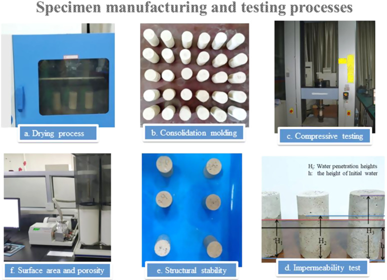
With an increase in the mining depth and breadth of coal mines in China, water inrush accidents from the roof bed separation of a mining face have become more frequent. A similar simulation experiment in the laboratory is an important way to study the dynamic seepage processes of separation water and explore the mechanism of roof bed separation formation. In this study, we develop a new type of similar material to simulate strata separation. The skeleton of this material is made from river sand, while nanosized calcium carbonate, Ca-bentonite, gypsum, and emulsified wax act as additives. These synthetic materials are then used for the compressive strength experiment, the water permeation height experiment, the structural stability experiment, and the microscopic analysis. Besides, a physical experiment is also conducted to verify the effectiveness of this new similar material. This work could provide the scientific basis for the prediction and control of water accidents caused by the separation strata.
1. Introduction
In recent years, with an increase in the mining depth and breadth of coal mines in China, a problem has arisen whereby large quantities of separation water accumulate in the space between separated overburden strata. Once a certain water pressure threshold is reached, the separation water in the upper separation space breaks through the lower confining bed and enters the coal mining face, which not only seriously threatens the safety of underground miners but also results in large economic losses for the coal mining industry.1−5 This new type of water-related accident is referred to as the water accident caused by separated overburden strata.1−4,6 Such accidents are characterized by instantaneous flooding with a large volume of water, no obvious signs of water inrush, short duration, and complicated and varied mechanisms.7,8 In the past ten years, separation water inrush accidents have greatly affected safe mining production (see Table 1 for details).
Table 1. Water Inrush Accidents Caused by Separated Overburden Strata in Coal Mines.
| region | coal mines | accident date | accident situation |
|---|---|---|---|
| Anhui province | Yangliu Coal Mine | July 17, 2017 | During the mining of Permian 10 coal, a mixture of water and gas gushed out of the borehole into the ground, with a water inrush quantity that reached 7845.6 m3. Its potential threat was quite large. |
| Shandong province | Huafeng Coal Mine | September 2005 | During the advancing process of the 1409 mining face, several water penetration accidents occurred. The maximum water penetration quantity was 720 m3/h. |
| Jining no. 2 Coal Mine | October 6, 2007 | The water level in the goaf of the 11 305 mining face suddenly increased several times, and the water accumulation quantity increased to 163 000 m3 within a very short period of time. | |
| Ningxia province | Hongliu Coal Mine | March 25, 2010 | A total of four water penetration accidents occurred in the 1121 mining face, with the maximum water penetration quantity reaching 3000 m3/h. After investigation, the water was found to primarily come from the coarse sandstone at the bottom of the Jurassic Zhiluo Formation in the roof. |
| Gansu province | Daliu Coal Mine | April 3, 2013 | Water penetration accidents occurred in the roof of the 1402 working face, with the maximum water penetration quantity reaching 430 m3/h. The source of the water was the glutenite water of the Zhidan Group. |
| Xinjiang province | Shajihai Coal Mine | December 2016 | The total water inrush quantity in the exploration drainage and goaf areas was 38 316.2 m3. The source of the inflow water was the medium-coarse sandstone aquifer of the Xishanyao Formation. |
There is currently an urgent need for in-depth studies on this new type of water accident, which play an important role in the effective prediction and prevention. Many researchers have conducted extensive studies on these issues to determine the mechanism of overburden strata separation (Figure 1),2,4,9−15 evaluate the water inrush risk,3,16−19 and propose the corresponding preventative measures.2,9,11,13,15,20,21 For example, Cao9 investigated the influence of faults22 on the separation strata formation through similar simulation experiments in the laboratory. Lei12 simulated the propagation of transverse and longitudinal fractures due to strata separation using 3DEC simulation software developed by ITASCA Consulting Group. Almost all of the literature has revealed that similar simulation experiments in laboratories and numerical simulations are effective means to study the strata separation and water inrush. However, the usual similar materials tend to resolve in water and thus cannot effectively reflect the seepage and erosion processes of separation water.
Figure 1.
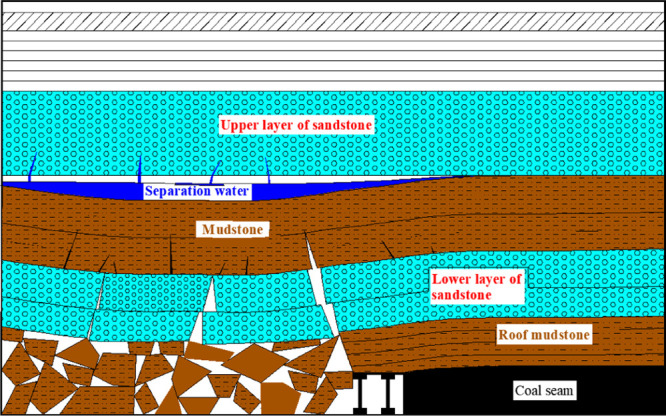
Schematic diagram of separation water formation.
In this paper, we develop a new type of similar material that could reflect the physical properties of the strata. Through similar simulation experiments, we could visualize the formation of an overburden strata separation and observe the water breakthrough from the aquiclude. This approach helps us analyze the failures of overburden strata and develop seepage equations of separation water. Our new type of similar material consists of river sand (raw material), nanosized calcium carbonate, gypsum, Ca-bentonite, and emulsifying wax (additives). The paraffin emulsion has good hydrophobicity,23 and it is an important similar waterproof material. The properties of this new type of similar material were studied using the compressive strength experiment,5,24 the impermeability experiment,5,24 the structural stability experiment, and the microscopic analysis. Finally, the feasibility of this new type of material was verified through a similar simulation experiment, which provided the scientific basis for the prediction and control of water accidents caused by the separation strata.
2. Results and Discussion
2.1. Compressive Strength Characteristics of the Similar Material
The compressive strength test was conducted using a Shimadzu AGX-250 electronic universal testing machine. The test results of the specimens are shown in Table 2.
Table 2. Compressive Strength of Each Specimen.
| number | compressive strength (MPa) | number | compressive strength (MPa) |
|---|---|---|---|
| A | 1.59 | H | 0.81 |
| B | 1.22 | I | 0.64 |
| C | 0.75 | J | 1.06 |
| D | 0.67 | K | 0.87 |
| E | 0.62 | L | 0.78 |
| F | 1.04 | M | 0.70 |
| G | 0.85 |
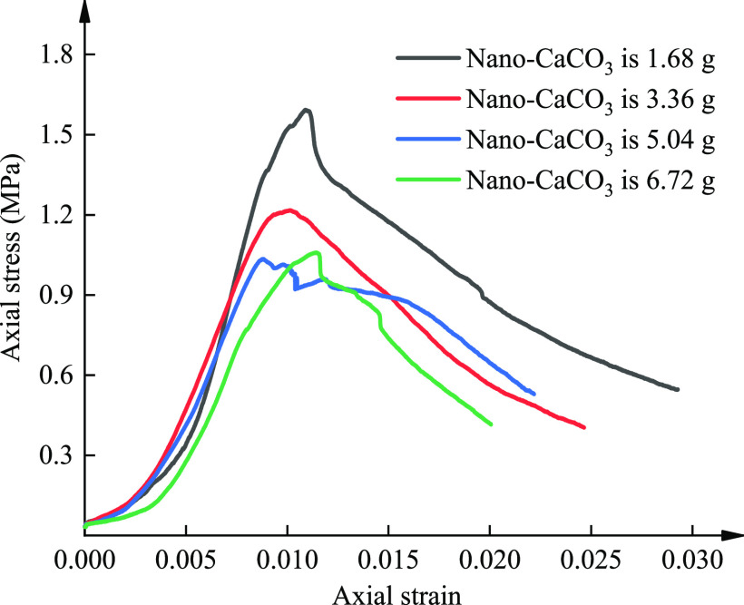
The stress–strain curves of four specimens that did not contain aqueous wax are shown in Figure 2. From the figure, we can observe that with an increase in the nanosized calcium carbonate proportion, the compressive strength of the specimens first decreases and then gradually reaches a stable value.
Figure 2.
Stress–strain curves of four specimens that did not contain aqueous wax.
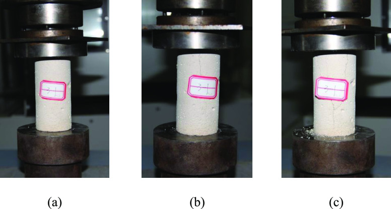
The whole compression process can be divided into three stages, as shown in Figure 3. The first stage is the full compaction stage when the axial compressive strain is less than 0.005. In this stage, as the load increased, the void spaces inside the skeleton were compressed and the solid particles gradually moved closer. The second stage is the elastic deformation stage when the axial compressive strain is between 0.005 and 0.01. In this stage, the stress–strain curve was approximately a straight line. The third stage is the yield stage. In this stage, large penetrating cracks gradually appeared throughout the specimens, and the axial stress began to decrease after reaching the peak strength while the axial compressive strain continued increasing.
Figure 3.
Compression process can be divided into (a) full compaction stage, (b) elastic deformation stage, and (c) yield stage.
2.2. Impermeability Characteristics of a Similar Material
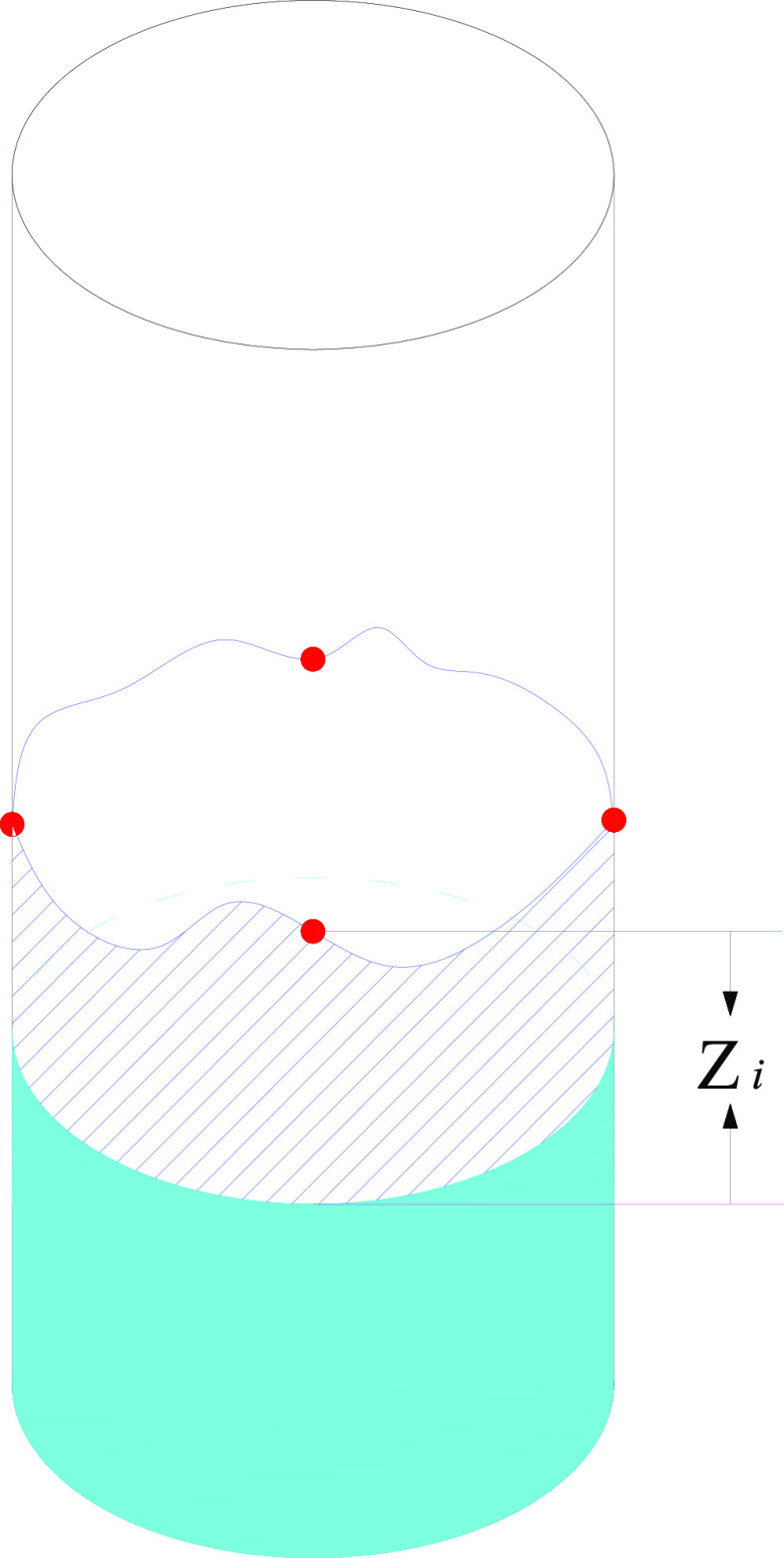
The impermeability experiment was performed under hydrostatic pressure. The impermeability of a specimen was determined by the penetration height of water. The initial water depth in the experimental containers was designed to be 10, 30, and 50 mm since we want to test the impermeability characteristics under different initial water depths. The experiment lasted for 3.5 h, and measurements were taken every half hour. For each test, the average penetration height of four different points at the current water penetration curve of the specimen was calculated and recorded, as shown in Figure 4.
Figure 4.
Schematic diagram of the penetration height of a specimen. The height of the solid blue region is the initial water depth.
2.2.1. Effect of Wax–Water Ratio
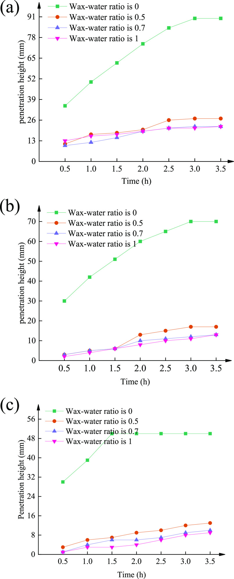
The evolution of penetration height was grouped by the initial water depth, and the results of 12 curves are shown in Figure 5. Note the wax–water ratio is defined as the mass of the emulsified wax divided by the sum of the emulsified wax mass and water mass. The specimen with zero wax–water ratio was permeable and water gradually permeated to the top of the specimen. As the wax–water ratio increased from 0 to 1, the permeation rate and the final water penetration height gradually decreased.
Figure 5.
Water penetration height when the initial water depth is (a) 10 mm, (b) 30 mm, and (c) 50 mm.
2.2.2. Effect of Initial Water Depth
Now, the evolution of penetration height was grouped by wax–water ratio, and the same 12 curves are shown in Figure 6. We can find that when the wax–water ratio was 0, the changes in the water depths had no influence on the water penetration height of the specimens, while a nonzero wax–water ratio could inhibit the water penetration height differences among different initial water depths.
Figure 6.

Water penetration height when the wax–water ratio is (a) 0, (b) 0.5, (c) 0.7, and (d) 1.0.
2.2.3. Summary
The aqueous paraffin wax emulsion could inhibit the solubility of dihydrate gypsum and thus increase the water resistance of the specimen. In addition, Ca-bentonite can absorb large quantities of water, which produces an expansion effect and squeezes the pore spaces around itself.
2.3. Structural Stability Experiment
Figure 7 shows the structural stability experiment process for all specimens. By analyzing the changes of the specimens, we can obtain a preliminary understanding of the stability of the structure. During the initial immersion period, bubbles appeared on the surface of all specimens, which indicates a fast water absorption rate. After being immersed in water for 8 h, the overall structures of the specimens remained intact with no changes. After being immersed in water for 24 h, the surface structures of some specimens fell off, while the remaining specimens remained intact with no substantial changes. After being immersed in water for 48 h, the surface structures of all specimens fell off to varying degrees, but the main structure remained intact.
Figure 7.
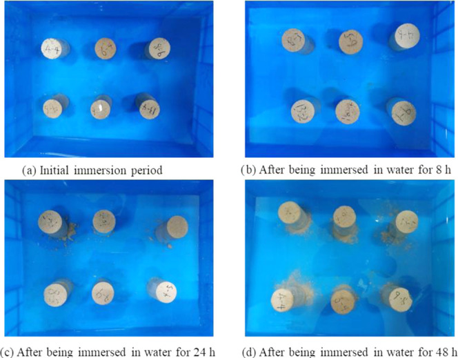
Structural stability experiment process.
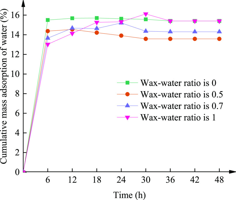
In Figure 8, we plotted the cumulative mass adsorption of water versus time for different wax–water ratios. A comparison showed that the specimen with a higher wax–water ratio had a lower mass absorption in the beginning, and it experienced a slight increase in mass absorption after a long period of immersion.
Figure 8.
Evolution of mass absorption under different wax–water ratios.
2.4. Microscopic Analysis of the Similar Material
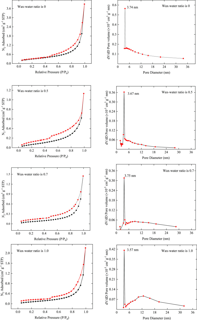
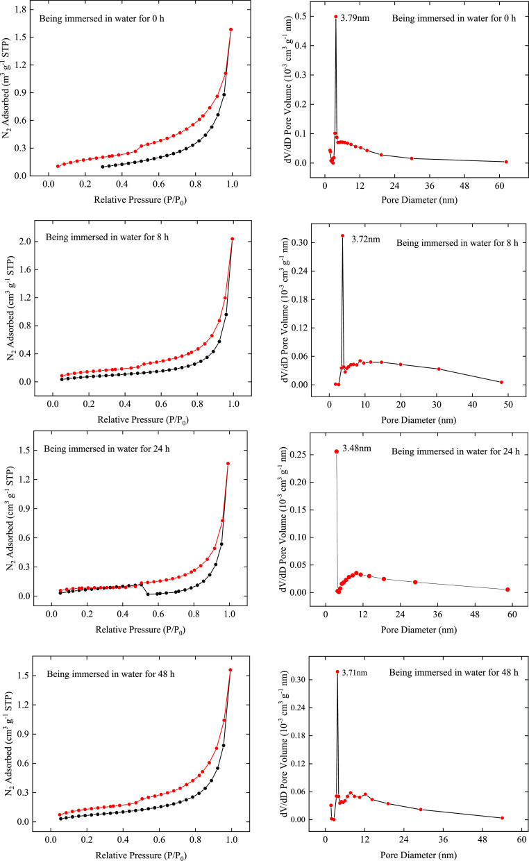
A fully automated specific surface area and porosity analyzer (ASAP2460) was chosen for testing the specific surface area and porosity of the similar material. The microstructure characteristics under different wax–water ratios and different immersion periods are summarized in Tables 3 and 4. The detailed results are provided in Figures 9 and 10. In general, with the increase in the immersion time, the physical and chemical properties of the specimens were weakened to a certain extent, which is consistent with the performance of the actual coal mine roof strata. Thus, it is beneficial for us to use this similar material to study the water inrush from strata separation.
Table 3. Specific Surface Area, Total Pore Volume, and Pore Size of the Dry Specimens under Different Wax–Water Ratios.
| sample | specific surface area (m2/g) | total pore volume (cm3/g) | pore size (nm) |
|---|---|---|---|
| wax–water ratio is 0 | 1.0603 | 0.002721 | 10.2653 |
| wax–water ratio is 0.5 | 0.3131 | 0.000842 | 10.7536 |
| wax–water ratio is 0.7 | 0.2802 | 0.001023 | 14.5950 |
| wax–water ratio is 1 | 0.3617 | 0.001388 | 15.3529 |
Table 4. Specific Surface Area, Total Pore Volume, and Pore Size of the Specimen J under Different Immersion Periods.
| sample | specific surface area (m2/g) | total pore volume (cm3/g) | pore size (nm) |
|---|---|---|---|
| being immersed in water for 0 h | 0.3849 | 0.001223 | 12.7120 |
| being immersed in water for 8 h | 0.3201 | 0.001124 | 14.0495 |
| being immersed in water for 24 h | 0.2949 | 0.000660 | 8.9550 |
| being immersed in water for 48 h | 0.3014 | 0.001063 | 14.1090 |
Figure 9.
Detailed microscopic analysis results (part I).
Figure 10.
Detailed microscopic analysis results (part II).
2.5. Comprehensive Evaluation
Through a comprehensive analysis of the compressive strength characteristics, impermeability characteristics, structural stability, and microstructure characteristics, specimen D, specimen I, and specimen K were chosen to simulate sandy mudstone, mudstone, and siltstone, respectively.
2.6. Verification through a Physical Experiment
To verify the practicality of the new similar material, we used it in a physical experiment to simulate a mining face in the first mining area of the Hongliu Coal Mine. The technology of longwall mining on the strike of a single seam and full-seam mining was adopted for the mining face, and the full-caving method was used for roof management. Based on hydrogeological data from exploration drill holes near the working face, the main source of water inflow is known to be the coarse sandstone aquifer located at the bottom of the Jurassic Zhiluo Formation at the roof. The unit water inrush quantity of the aquifer is q < 0.1 L/(m s). When this mining face was back-stopped, the water inrush quantity suddenly increased, which resulted in the forced shutdown of the mining face to drain the water. It turned out that separation strata had developed between the upper section of the coarse sandstone of the lower Zhiluo Formation and the mudstone in the lower Zhiluo Formation. Water in the lower section of the coarse sandstone aquifer of the lower Zhiluo Formation seeped into the cavity of the separation strata and gradually accumulated there.
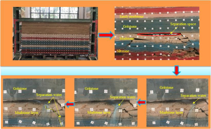
The physical experiment was based on a two-dimensional simulation test bed for similar materials. The experimental equipment comprised of the simulation test bed for similar materials, a roof loading system, and a separation water loading system. The specific experimental process is shown in Figure 11.
Figure 11.
Physical experimental process of water inrush from strata separation.
The experimental design process was as follows.
The designed simulation model for similar materials was 3 × 0.4 × 1.5 m3 (l × w × h). The coal seam advancing distance was 2 m.
Fifty centimeters of coal pillars were reserved on both sides of the coal seam, and the additional effects generated by boundaries on both sides were eliminated.
After the separation space was formed, organic glass was added to the areas on both sides of the separation strata to prevent the separation water from flowing completely out of the space from the sides.
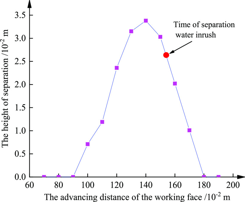
Figure 11 shows that with the gradual advancing of the coal seam, the overburden strata bent and subsided, resulting in the asynchronous collapse of various strata. The weak sides of the coarse sandstone, which were 21 cm from the coal seam height and lower mudstone, were damaged, resulting in a separation space that formed between the rock strata. The mudstone layer in the lower part of the separation strata effectively blocked the seepage of the separation water; however, in the process of subsiding, a certain degree of deformation and damage occurred because of the mining operation, which caused a reduction in its blocking thickness. After the separation space was formed, its maximum development height increased gradually with the advancing distance of the working face, as shown in Figure 12.
Figure 12.
Evolution of the strata separation with the advancing distance of the working face.
With the continuous advancing of the coal seam, the separation zone gradually became larger and received additional water from the upper aquifer. Fissure water and pore water seeping downward from the upper aquifer gradually accumulated in the separation space. Finally, the separation water was collected in the separation space. Large quantities of separation water were concentrated near the top of the mudstone. Lower separation water seeped into and eroded the upper mudstone, resulting in the softening of the mudstone. Finally, the water moved through the bottom mudstone fractures, gradually seeped into the mining area, and ultimately led to a separation water inrush accident.
The experimental results show that the separation water that seeped downward contained small quantities of fine sand and that the water inrush quantity at later stages obviously increased. Our analysis indicates that the separation water eroded the mudstone fracture surface, which resulted in increasingly wide water inrush pathways. This finding explains why the instantaneous water inrush quantity increases when a separation water accident occurs.
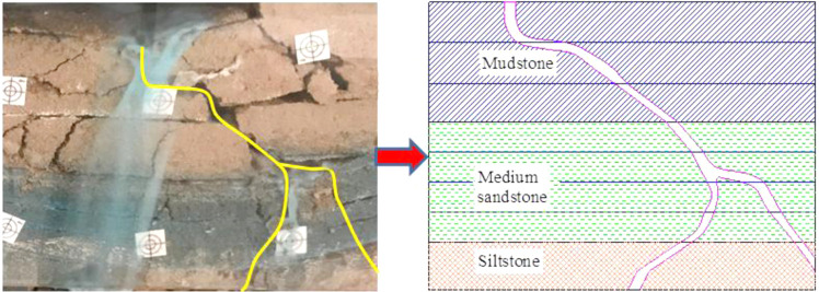
The erosion effect of the separation water on the fractures around the pathways is very important, but this phenomenon could not be quantified experimentally. By taking the water inrush pathway in the above experiment as the prototype, geometric modeling was conducted with CAD software to analyze the erosion effects of the separation water, as shown in Figure 13.
Figure 13.
Constructing the geometric model (water channel) for numerical simulation from physical experiment.
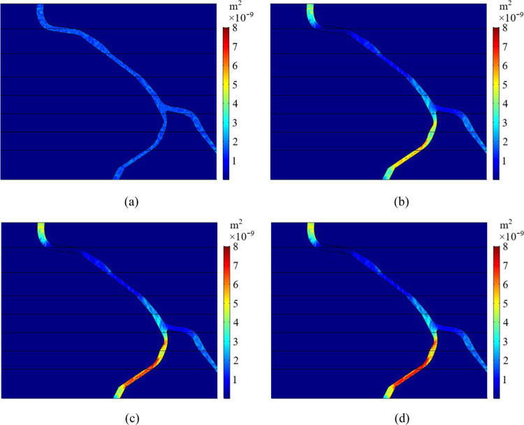
The permeability of rock strata, K, is a parameter used to characterize the permeability performance of porous media. It can be used to clearly distinguish whether the fracture boundary of rock strata is subject to erosion. The numerical simulation software COMSOL Multiphysics was selected to perform the numerical simulation in this study. The result is shown in Figure 14.
Figure 14.
(a) Initial permeability of the water channel. (b) Permeability of the water channel after 16 h. (c) Permeability of the water channel after 32 h. (d) Permeability of the water channel after 48 h.
With the gradual advancement of the mining face, many fractures were produced because of overburden strata caving and breaking. The seeping separation water gradually linked the rock fractures and produced water inrush pathways that endangered mining activities at the lower coal mining face. Under the action of dynamic water pressure, the separation water eroded the surface of the water inrush pathways, which caused the loss of many particles. The permeability gradually increased over time and tended to stabilize during the later period. The structure of the rock strata around the water inrush pathway gradually stabilized, and the water inrush quantity also increased over time.
Accordingly, the physical properties of the new materials studied here were consistent with the mechanical properties of the rock in mines. The materials can assist in the analysis of the formation process and the seepage mechanisms of accidents caused by the separation water. They can also be used to further enrich the theoretical methods for the prediction and prevention of accidents caused by the separation water and provide a reliable scientific basis for the safe mining of coal seams.
3. Conclusions
To study the water inrush from strata separation, a new type of similar material was developed. The material contained river sand and various additives. Through several lab tests and experiments, we obtain the following conclusions:
(1) The physical properties, mechanical properties, and microscopic structures of the new similar material were good. We used specimen D, specimen I, and specimen K to simulate sandy mudstone, mudstone, and siltstone, respectively.
(2) The optimal wax–water ratio of the new similar material was 0.7. The aqueous wax emulsion fully reacted with gypsum to form a dense, water-blocking layer. It was also concluded that a similar material containing aqueous wax emulsion showed good long-term stability.
(3) The actual seepage process was analyzed through a physical simulation experiment. Numerical simulation was used to conduct a quantitative analysis of the separation water seepage and erosion process.
4. Specimen Preparation
4.1. Analysis of the Material Constituents
4.1.1. River Sand
The selected river sand was taken from a river near Qingdao, and the selected particle size range was 0.1–0.9 mm.
4.1.2. Nanosized Calcium Carbonate
The nanosized calcium carbonate used in the experiments was provided by the Jiujiang Huirong New Material Co., Ltd., Jiangxi Province. It was used to adjust the rigidity, toughness, and strength of the material. The chemical composition and fundamental properties of the nanosized calcium carbonate are shown in Table 5.
Table 5. Chemical Composition and Fundamental Properties of the Nanosized Calcium Carbonate.
| average particle size (nm) | pH value | specific surface area (m2/g) | activation degree (%) | CaCO3 (%) | MgO (%) |
|---|---|---|---|---|---|
| 50–100 | 7.5–10 | >18 | >95 | >90 | <0.8 |
4.1.3. Molding Gypsum
The molding gypsum used in the experiments primarily comprised of α-hemihydrate calcium sulfate with some additives, including clay and organic matter. The chemical composition of the molding gypsum is shown in Table 6.
Table 6. Chemical Composition of the Molding Gypsum.
| components | CaO | SO3 | H2O |
|---|---|---|---|
| content (%) | 32.5 | 46.6 | 20.9 |
4.1.4. Ca-bentonite
The Ca-bentonite used in the experiments was provided by the Aotai Mineral Processing Plant in Lingshou County, Shijiazhuang, Hebei Province. The bentonite had a density of approximately 0.9 g/cm3 and a mesh of 600. The chemical composition of Ca-bentonite is shown in Table 7.
Table 7. Chemical Composition of the Ca-bentonite.
| components | SiO2 | Al2O3 | Fe2O3 | MgO | CaO | TiO2 | K2O | Na2O |
|---|---|---|---|---|---|---|---|---|
| content (%) | 71.39 | 14.4 | 1.71 | 1.52 | 1.20 | <0.1 | 0.44 | 0.4 |
4.1.5. Aqueous paraffin wax emulsion
The aqueous paraffin wax emulsion was provided by the Jingyi Plastic Chemical Materials Plant, Dongguan, Guangdong Province. It is an oily organic substance with strong cohesive properties and is insoluble in water. The fundamental properties of aqueous paraffin wax emulsion are shown in Table 8.
Table 8. Fundamental Properties of the Aqueous Paraffin Wax Emulsion.
| appearance | solid content | pH value | melting point (°C) |
|---|---|---|---|
| gray-white | 30% | 7–9 | 0 |
4.2. Specimen Manufacturing Process
Thirteen specimens with different constituents’ proportions were used to understand the influence of nanosized calcium carbonate and aqueous paraffin wax emulsion on the physical properties of similar material (Table 9). Ca-bentonite and molding gypsum were used as additives, and they accounted for 0.5 and 10% of the solid material, respectively. The total mass of the solid material for all specimens was 336 g. The manufacturing processes are described as follows.
Table 9. Detailed Composition of Each Specimen.
| number | river sand (g) | nanosized calcium carbonate (g) | aqueous wax emulsion (g) | water (g) |
|---|---|---|---|---|
| A | 299.04 | 1.68 | 0 | 84 |
| B | 297.36 | 3.36 | 0 | 84 |
| C | 297.36 | 3.36 | 42 | 42 |
| D | 297.36 | 3.36 | 58.8 | 25.2 |
| E | 297.36 | 3.36 | 84 | 0 |
| F | 295.68 | 5.04 | 0 | 84 |
| G | 295.68 | 5.04 | 42 | 42 |
| H | 295.68 | 5.04 | 58.8 | 25.2 |
| I | 295.68 | 5.04 | 84 | 0 |
| J | 294 | 6.72 | 0 | 84 |
| K | 294 | 6.72 | 42 | 42 |
| L | 294 | 6.72 | 58.8 | 25.2 |
| M | 294 | 6.72 | 84 | 0 |
First, the raw materials were weighed according to the proportions shown in Table 9, and they were added to the mixing bowl in sequence until they were mixed thoroughly. After that, the mixture was poured into a 50 × 100 mm standard mold, and the mold was shaken for approximately 2 min on a shaking table. Second, the specimens were dried by placing them in a vacuum drying box at 70 °C for 3 days. The specimens were dried until they could be demolded. Finally, the demolded specimens were cured by placing them in a curing box for approximately 5 days. The curing conditions of the specimens are a temperature of 30 °C and a humidity of 55%.
Acknowledgments
This paper was supported by grants from the National Natural Science Foundation of China (51774199) and the Natural Science Foundation of Shandong Province for the support of major basic research projects (ZR2018ZC0740). The authors would like to sincerely thank the Hongliu Coal Mine of Shenhua Ningxia Coal Industry Group Co., Ltd., for providing the geological data.
The authors declare no competing financial interest.
References
- Gui H.; Lin M.; Song X. Identification and Application of Roof Bed Separation (Water) in Coal Mines. Mine Water Environ. 2018, 37, 376–384. 10.1007/s10230-018-0518-0. [DOI] [Google Scholar]
- Li H.; Chen Q.; Shu Z.; Li L.; Zhang Y. On Prevention and Mechanism of Bed Separation Water Inrush for Thick Coal Seams: A Case Study in China. Environ. Earth Sci. 2018, 77, 759 10.1007/s12665-018-7952-y. [DOI] [Google Scholar]
- Lu Q.; Li X.; Li W.; Chen W.; Li L.; Liu S. Risk Evaluation of Bed-Separation Water Inrush: A Case Study in the Yangliu Coal Mine, China. Mine Water Environ. 2018, 37, 288–299. 10.1007/s10230-018-0535-z. [DOI] [Google Scholar]
- Yan H.; He F.; Yang T.; Li L.; Zhang S.; Zhang J. The Mechanism of Bedding Separation in Roof Strata Overlying a Roadway within a Thick Coal Seam: A Case Study from the Pingshuo Coalfield, China. Eng. Failure Anal. 2016, 62, 75–92. 10.1016/j.engfailanal.2015.12.006. [DOI] [Google Scholar]
- Zhang W.; Zhu X.; Xu S.; Wang Z.; Li W. Experimental Study on Properties of a New Type of Grouting Material for the Reinforcement of Fractured Seam Floor. J. Mater. Res. Technol. 2019, 8, 5271–5282. 10.1016/j.jmrt.2019.08.049. [DOI] [Google Scholar]
- Wang S.; Li X.; Wang S. Separation and Fracturing in Overlying Strata Disturbed by Longwall Mining in a Mineral Deposit Seam. Eng. Geol. 2017, 226, 257–266. 10.1016/j.enggeo.2017.06.015. [DOI] [Google Scholar]
- Shao J.; Zhang Q.; Sun W.; Wang Z.; Zhu X. Numerical Simulation on Non-Darcy Flow in a Single Rock Fracture Domain Inverted by Digital Images. Geofluids 2020, 2020, 1–13. 10.1155/2020/8814327. [DOI] [Google Scholar]
- Zhang Q. Hydromechanical Modeling of Solid Deformation and Fluid Flow in the Transversely Isotropic Fissured Rocks. Comput. Geotech. 2020, 128, 103812 10.1016/j.compgeo.2020.103812. [DOI] [Google Scholar]
- Cao H. D.Study on Prevention & Control Technology and Disaster-caused Mechanism of Bed Separation Water Body in Overburden Strata During Coal Seam Mining, China Coal Research Institute, 2018. (in Chinese).
- Fan K.; Li W.; Wang Q.; Liu S.; Xue S.; Xie C.; Wang Z. Formation Mechanism and Prediction Method of Water Inrush from Separated Layers within Coal Seam Mining: A Case Study in the Shilawusu Mining Area, China. Eng. Failure Anal. 2019, 103, 158–172. 10.1016/j.engfailanal.2019.04.057. [DOI] [Google Scholar]
- Fang G.; Jin D.-w. Research on the Roof Stratifugic Water Inrush Mechanism and Control in Tongchuan Yuhua Coal Mine. Coal Geol. Explor. 2016, 44, 57–64. [Google Scholar]
- Lei L.Evolution of Master Fractures and Water Inrush Forecast for Fully Mechanized Top-Coal Caving Mining of Extremely Thick Coal Seam, China University of Mining and Technology, 2018. (in Chinese).
- Qiao W.; Huang Y.; Yuan Z.; Guo W.; Zhou D. Formation and Prevention of Water Inrush from Roof Bed Separation with Full-Mechanized Caving Mining of Ultra Thick Coal Seam. Chinese J. Rock Mech. Eng. 2014, 33, 2076–2084. [Google Scholar]
- Wang G.; Wu M.; Wang R.; Xu H.; Song X. Height of the Mining-Induced Fractured Zone above a Coal Face. Eng. Geol. 2017, 216, 140–152. 10.1016/j.enggeo.2016.11.024. [DOI] [Google Scholar]
- Zhang Y.; Li D.; Lv X.; Niu C.; Wang S. Study on Formation Mechanism and Control Technology of Stratifugic Water in Shajihai Coal Mine. Coal Eng. 2017, 49, 107–109. [Google Scholar]
- Zhang H. Q.; He Y. N.; Tang C. A.; Ahmad B.; Han L. J. Application of an Improved Flow-Stress-Damage Model to the Criticality Assessment of Water Inrush in a Mine: A Case Study. Rock Mech. Rock Eng. 2009, 42, 911–930. 10.1007/s00603-008-0004-2. [DOI] [Google Scholar]
- Zhang W.; Li B.; Yu H. The Correlation Analysis of Mine Roof Water Inrush Grade and Influence Factors Based on Fuzzy Matter-Element. J. Intell. Fuzzy Syst. 2016, 31, 3163–3170. 10.3233/JIFS-169202. [DOI] [Google Scholar]
- Zhang W.; Wang Z.; Shao J.; Zhu X.; Li W.; Wu X. Evaluation on the Stability of Vertical Mine Shafts below Thick Loose Strata Based on the Comprehensive Weight Method and a Fuzzy Matter-Element Analysis Model. Geofluids 2019, 2019, 3543957 10.1155/2019/3543957. [DOI] [Google Scholar]
- Zhang W.; Wang Z.; Zhu X.; Li W.; Gao B.; Yu H. A Risk Assessment of a Water-Sand Inrush during Coal Mining under a Loose Aquifer Based on a Factor Analysis and the Fisher Model. J. Hydrol. Eng. 2020, 25, 04020033 10.1061/(ASCE)HE.1943-5584.0001936. [DOI] [Google Scholar]
- Gui H.; Tong S.; Qiu W.; Lin M. Research on Preventive Technologies for Bed-Separation Water Hazard in China Coal Mines. Appl. Water Sci. 2018, 8, 7 10.1007/s13201-018-0667-0. [DOI] [Google Scholar]
- Lin Q.; Qiao W. Water Prevention and Control Technology of Roof Bed Separation in Cuimu Mine. Coal Sci. Technol. 2016, 44, 129–134. [Google Scholar]
- Zhang Q.; Zhu H. Collaborative 3D Geological Modeling Analysis Based on Multi-Source Data Standard. Eng. Geol. 2018, 246, 233–244. 10.1016/j.enggeo.2018.10.001. [DOI] [Google Scholar]
- Hu S. N.; Zhang J. H.; Du L.; Li J. G. Surface Modification of a Low Rank Coal with Paraffin Emulsion and its Effect on Performances of Coal Water Slurry. Chem. Ind. Eng. Prog. 2018, 37, 1421–1425. [Google Scholar]
- Zhu X.; Zhang Q.; Zhang W.; Shao J.; Wang Z.; Wu X. Experimental Study on the Basic Properties of a Green New Coal Mine Grouting Reinforcement Material. ACS Omega 2020, 5, 16722–16732. 10.1021/acsomega.0c01626. [DOI] [PMC free article] [PubMed] [Google Scholar]


