

Abstract
We present the design of a powered knee-ankle prosthetic leg, which implements high-torque actuators with low-reduction transmissions. The transmission coupled with a high-torque and low-speed motor creates an actuator with low mechanical impedance and high backdrivability. This style of actuation presents several possible benefits over modern actuation styles in emerging robotic prosthetic legs, which include free-swinging knee motion, compliance with the ground, negligible unmodeled actuator dynamics, less acoustic noise, and power regeneration. Benchtop tests establish that both joints can be backdriven by small torques (~1–3 Nm) and confirm the small reflected inertia. Impedance control tests prove that the intrinsic impedance and unmodeled dynamics of the actuator are sufficiently small to control joint impedance without torque feedback or lengthy tuning trials. Walking experiments validate performance under the designed loading conditions with minimal tuning. Lastly, the regenerative abilities, low friction, and small reflected inertia of the presented actuators reduced power consumption and acoustic noise compared to state-of-art powered legs.
Index Terms—: rehabilitation robotics, actuator design, powered prostheses, backdrivability
I. Introduction
Use of conventional passive prostheses after lower-limb loss results in gait that is slower, less stable, and less energy efficient than able-bodied locomotion [1], [2]. Passive prostheses aim to alleviate the effects of amputation using mechanisms such as springs, cams, and dampers to mimic normative gait patterns. However, passive prostheses are limited in functionality due to the fact that such mechanisms can only dissipate energy that the user introduces. Although these passive devices restore some functionality, amputees are typically left with an asymmetric gait [3]. Moreover, most devices are designed for level-ground walking conditions and do not adequately facilitate tasks such as sit-to-stand or stair ascent/descent. Semi-active prostheses, such as the Ottobock C-Leg, utilize microprocessors to control the damping of joints via small actuators that manipulate hydraulic valves during the user’s gait [4], [5]. This approach allows for a single product to be easily adaptable to a variety of subjects, environments, and tasks, but semi-active devices can still only dissipate energy from the user’s gait. Powered prostheses can actively inject energy and therefore have greater capability to restore mobility and quality of life to those who live with the loss of a limb.
In the last decade, a great amount of research has gone into the design and control of powered prosthetic limbs, resulting in several prosthetic devices that implement a variety of actuation schemes [6]–[9]. Rigid, or non-backdrivable actuators, that implement transmissions such as worm gears [10] or cam-follower/leadscrews [11], have recently been implemented in order to reduce the size and weight of the prosthesis. Several other prosthetic legs implement actuators with low-backdrivability, or high-impedance. Such actuators commonly include high-speed, low-torque motors with high-ratio transmissions, such as ball screws or multiple/belt gear stages [4], [6], [12]–[24]. This high-impedance actuation scheme, which typically consists of reduction ratios greater than 100:1, results in more rigid joints and large reflected inertias. This can cause more painful impact forces on the residual limb after extended use. This also forces the knee swing to be actively controlled rather than naturally free-swinging (like, for example, the C-Leg), which results in higher energy consumption and reduced battery life. Additionally, more meshing or rolling parts in the transmission result in more acoustic noise that is bothersome to patients. A recently developed prosthetic leg implements a transmission with a reduced reduction ratio of ~50:1 [25], but the resulting actuator impedance is still high enough to share some of the limitations discussed above.
In the past few years, legged robots such as the quadruped MIT Cheetah [26], biped Cassie [27], and others [28]–[32] have embraced high-torque motors with low-ratio or no transmissions. High-torque, low-reduction-ratio actuators (also referred to as low-impedance actuators) offer several benefits for legged robotics that are also desirable in powered prostheses. The lower mechanical impedance (inertias and frictional losses) of these actuators minimizes the effect of unmodeled dynamics, which in turn simplifies an otherwise complex control problem, increases robustness, and makes the system behave closer to an ideal model. Force control in these actuators can be comparable to series elastic actuators without their design and manufacturing complexities and low bandwidth [17], [33]. Low-impedance actuators are also compliant, which aids in regenerating energy and mitigating impact forces [34].
We propose that low-impedance actuators also have benefits specific to powered prostheses, including passive knee-swing motion, energy sharing between joints, acoustic sound reduction, and compliance with the ground through impedance control. A free-swinging knee joint allows for a more natural gait, while reducing the power requirements of the actuator during swing phase. Energy sharing phases of gait such as mid-stance, where the ankle regenerates energy while the knee demands it, can lead to longer periods of untethered operation, which is critical for robotic legs in consumer applications. The low mechanical impedance from reduced friction and gear meshings can lead to a quieter device, which is crucial for the clinical acceptance of powered prosthetic legs. Lastly, the implementation of biological joint impedances can promote natural compliance with the ground and provide smoother touchdown impacts, which can in turn improve efficiency of the system and comfort for the user. Although there have been attempts to control prosthesis joints using open-loop torque control [18], the non-negligible dynamics of the actuator would considerably affect the joint torque and thus requiring lengthy sessions of tuning impedance parameters [35].
In the process of designing low-impedance actuators, transmission design is a critical problem. Single-stage planetary transmissions are extremely efficient and have less intrinsic impedance than multi-stage transmissions, but are typically limited to ratios below 10:1. Therefore, efficient single-stage transmissions usually require a customized motor design, such as [26], to achieve the high output torques required during legged locomotion. Other transmission choices used in robotic legs such as harmonic and cycloid gear drives exhibit other problems such as efficiency and manufacturing complexities, respectively [36]. To overcome these shortcomings, we propose using a single-stage stepped-planet compound planetary gear transmission (SPC-PGT) [37] coupled with a high torque-density motor. As we will show, the resulting actuator has low mechanical impedance and high backdrivability. Although this style of transmission has the same number of gears meshing as a single-stage planetary transmission, it offers a higher range of reduction ratios while maintaining high efficiency and low acoustic sound. The manufacturability of this transmission style is also simplified compared to previously mentioned styles.
This paper extends the benchtop validation of the powered transfemoral prosthetic leg presented in [38] through the implementation of a walking controller that utilizes the compliant nature of the leg’s actuators to facilitate smooth and easy switching between impedance and position control paradigms at different walking speeds. Moreover, the low impedance of the actuators allows for the direct use of estimated human joint impedance. This can simplify the implementation and tuning of the biomimetic walking controller compared to typical open-loop (no joint torque feedback) impedance control of actuators with non-negligible intrinsic impedance. Examining the leg during walking allows for the quantification of specific properties not measurable during benchtop testing, such as kinematics and kinetics, electrical power, and acoustic sound levels during normative loading conditions. We validate the actuator design in walking experiments with an able-bodied subject, demonstrating normative kinematics and pushoff power with reduced acoustic noise compared to previous designs. These tests also demonstrate that accurate impedance and torque control can be achieved without torque sensors. These sensors are removed in a revised assembly to minimize weight and volume for experiments with a transfemoral amputee subject. In these trials, the joint compliance facilitates energy regeneration and sharing between joints during periods of negative work, such as knee swing extension. This is useful to increase the efficiency of powered prostheses, which leads to extended battery life and usage time [9].
The mechatronic design of the powered prosthetic leg is presented in Section II, including the motor, transmission, electrical system, and structure of both joints. Section III introduces the leg’s control method implemented in Section IV. Section IV-A presents a series of benchtop experiments that characterize the velocity, torque, position tracking, and backdrive capabilities of the actuators. Section IV-B presents the setup and results of walking experiments, including power regeneration and acoustic sound reduction during walking at different speeds. Section V discusses the results and Section VI concludes the paper.
II. Hardware Design
A. Design Overview
The main objective of this prosthesis design is to achieve human-like joint impedance and dynamics, such that biological joint impedance values can be directly implemented into joint level control. To achieve this, the design must have negligible intrinsic joint inertia similar to human joints [39]. Therefore, our main design goal is to minimize the reflected inertia of the joint’s actuator while preserving the required torque capabilities. For reference, we aim for a substantially reduced actuator inertia compared to that of the state-of-art powered prosthesis (3rd Generation Vanderbilt Leg - knee actuator; 0.1032 kg·m2) [16]. Additionally, each actuator must be able to meet the necessary torque, velocity, position, and power requirements for level ground, stair ascent, and stair descent ambulation [39], [40], shown in Table I. Fig. 1 presents the required joint power and torque throughout the gait cycle for these tasks. We wish to exceed the peak torque and power capabilities of state-of-art prosthetic legs to fully match biological levels for heavier subjects and more demanding tasks, such as fast walking and stair ascent, which require ~130 Nm and ~350 W for a 75 kg individual. Note that the Vanderbilt leg is still capable of navigating stairs with a peak power of 200 W [41], [42]. Lastly, a self-imposed requirement of an adjustable shank length allows for a larger population of potential users.
TABLE I.
Knee and Ankle Requirements for a 75 kg subject
| Ankle Requirements | Knee Requirements | |
|---|---|---|
| Peak Torque | ~130 Nm | ~120 Nm |
| Velocity | 360°/s | 330°/s |
| Position | −28° to 20° | 0° to 105° |
| Peak Power | 345 W | 220 W |
Fig. 1.

Ankle (a & c) and knee (b & d) average joint powers and torques for healthy individuals (75 kg) [39], used for defining peak requirements of the powered prosthesis. Solid blue lines indicate level ground walking at fast speeds, where dotted red lines and dashed black lines represent stair ascent and descent, respectively.
Structural components of both actuators were optimized using the finite element analysis software, ANSYS, to ensure structural integrity for loading conditions of a 113.4 kg (250 lbs) user and against impacts (~3 times the subject weight) during level ground walking and stair ambulation. Most machined components were made of 7075-T6 aluminum, with a few shafts, gears, and bearings made of stainless steel. The leg was assembled in two iterations (Fig. 2): a preliminary one with torque sensors to validate the actuator capabilities during benchtop and able-bodied experiments, and a final one without torque sensors to reduce size and mass for amputee testing. The first assembly (Fig. 2, left) weighs approximately 6.05 kg without batteries or 6.61 kg with batteries. A weight breakdown is shown in Table II under “Preliminary Mass”. The leg’s Lithium-Polymer batteries, TP1600–4SA80X (Thunder Power, Nevada, USA), were kept off-board for benchtop and able-bodied experiments to ensure safety due to the potential for high regenerative currents. Note that for the second assembly, batteries were mounted on-board with active voltage monitoring of each individual cell. The knee actuator is ~13.7 cm wide (medial-lateral) by 12.9 cm deep (anterior-posterior). The ankle joint is ~6.5 cm wide by 7.6 cm deep. The section corresponding to the calf is ~11.8 cm wide by ~12.9 cm deep, which equates to approximately the 30th and 50th percentile of adult male and female calf circumference, respectively [43]. Furthermore, the distance from the top of the prosthesis to the knee center is ~7.8 cm, the minimum distance between the knee and ankle center is ~32.9 cm, and the distance from the ankle center and the ground is ~8.5 cm (including the cosmetic foot shell). Lastly, in an effort to reduce weight, components that are under minimal loading conditions were 3D printed in ABS plastic.
Fig. 2.

Final assemblies of the prosthetic leg. The image on the left displays the first version of the prosthesis (without batteries), which was used in benchtop and able-bodied testing. The image on the right displays the prosthesis after revisions were made for amputee experiments (i.e., torque sensor removal and on-board batteries).
TABLE II.
Approximate Mass of Leg Components
| Preliminary Mass (kg) | Revised Mass (kg) | |
|---|---|---|
| Motors | 1.18 | 1.18 |
| Transmissions | 1.39 | 1.32 |
| Torque Sensors | 0.38 | - |
| Load Cell | 0.19 | 0.19 |
| Structure | 2.29 | 2.17 |
| CF Foot | 0.30 | 0.30 |
| Electronics | 0.29 | 0.45 |
| Wiring | 0.03 | 0.05 |
| Li-Po Batteries | 0.56 | 0.43 |
| Total | 6.61 | 6.09 |
B. Revisions for Amputee Testing
The prosthesis required torque sensors in the testing and validation of its actuators during benchtop and able-bodied walking experiments. However, the results in Sections IV-A6 and IV-C1 demonstrated the precise open-loop torque control capabilities of the actuators, thus rendering the torque sensors unnecessary for further experimentation. Therefore, prior to amputee experiments, revisions were made to the structure of the prosthesis to remove both the knee and ankle torque sensors, shown on the right in Fig. 2. This is important because it led to a reduction in mass and volume of the leg, both of which are important when translating to the clinical setting. The removal of these sensors reduced the medial-lateral width of each actuator by ~1 cm. In addition to the removal of the torque sensors, smaller batteries (TP870–3SR70, Thunder Power) were selected to be mounted on the leg, which enabled untethered operation of the prosthesis. The mass of the entire prosthesis was reduced by ~0.52 kg, bringing the mass to 6.09 kg, including batteries. A breakdown of the revised mass is given in Table II.
C. Motor and Driver
High-torque motors typically used in industrial settings have large masses and volumes due to their robust housings and heat sinks. These motors are typically fixed in place, leading to minimal consideration of weight in their design. However, for implementation into a powered prosthetic leg, it was necessary for us to select a motor with high torque density, to ensure that our actuator could produce the required torque while remaining as light and compact as possible. To this end, we selected the ILM 85×26 motor kit, Robodrive, Germany. This frameless, brushless DC motor kit allowed for the design of a custom housing that can withstand loading conditions and dissipate heat, while reducing the weight compared to industrial motor assemblies. This motor has a manufacturer-rated torque of 2.6 Nm, peak torque of 8.3 Nm, and a maximum velocity of 1500 rpm. It is rated at 410 W, 11 A, and 48 V. A 25/100 Solo Gold Twitter motor driver (Elmo Motion Control, Petah Tikva, Israel) is used, which has a rated current of 17.6 A and a peak current of 35.2 A. The small size and mass of the driver (22.2 g) make it ideal for minimizing overall actuator size and mass.
D. Transmission
It was necessary to realize a transmission which would increase torque and decrease speed of the selected motor to fit within the desired torque/velocity range, while minimizing the reduction ratio, and therefore the reflected inertia. We determined that a reduction ratio of between 20:1 and 25:1 would be needed to achieve maximum torques, while maintaining desired speeds. Therefore, we designed a custom single-stage stepped-planet compound planetary gear transmission (SPC-PGT) with a 22:1 reduction. Considering the peak torque of the actuators (~183 Nm), the Lewis Factor Equation for gear tooth stress was used in the initial selection of off-the-shelf gears (SDP/SI, New York, USA), which were then revised using FEA analysis to optimize for weight. The SPC-PGT consists of one sun gear, one ring gear, and six planet gears. Traditional planetary gear transmissions have only three planet gears, which mesh between the sun and ring gears. However, the SPC-PGT used here calls for three sun-planet gears and three ring-planet gears. Each sun-planet gear is coaxially fixed in relation to its corresponding ring-planet gear through a keyed shaft. The sun-planet gears mesh with the sun gear, radially located 120° apart from each other. Similarly, the ring-planet gears are meshed with the ring gear, and are also radially located 120° apart from each other. The shafts of the planet gears are held on either side by what is commonly referred to as a planet carrier. The transmission assembly can be seen in Fig. 3.
Fig. 3.

CAD model of the planetary gear transmission. The image on the left illustrates an exploded view of the entire transmission (including planet carriers), while the right demonstrates the gear layout after assembly.
Although planetary gear transmissions have multiple input-to-output configurations, the presented gearbox uses the sun gear as the input and the planetary carrier as the output to achieve the maximum ratio possible given a specific gear set. A traditional single-stage planetary gear transmission with the same input to output configuration has a reduction ratio found by τm/τj = (Dr + Ds)/(Ds), whereas the reduction ratio of the single-stage SPC-PGT is found by τm/τj = 1+(DrDsp)/(DsDrp), where τm and τj are the motor and joint torque, respectively, and Ds, Dsp, Drp, and Dr are the sun, sun-planet, ring-planet, and ring gear diameter, respectively. Due to geometric constraints of a traditional planetary gear transmission, reduction ratios are typically limited to 10:1. However, the SPC-PGT can easily achieve higher reduction ratios in approximately the same geometric volume. Although the presented design differs from a traditional single-stage planetary gear transmission, the number of gears meshed together is the exact same, thus increasing the obtainable reduction ratio without decreasing efficiency or increasing acoustic sound [44]. This also minimizes backlash, which measured less than 36 arcmin (0.6°) during walking. Values between 30 and 120 arcmin (0.5° and 2°) are seen in similar robotic applications [36], [45]. Coupled to the high-torque motor, this transmission provides a continuous torque of 57.2 Nm and a peak torque of 182.6 Nm, demonstrating a larger scale application of a SPC-PGT transmission compared to the jumping robot in [45].
Lastly, it is necessary to estimate the reflected inertia of the actuator with this choice of motor and transmission. We obtained this estimate by taking the inertias from the CAD model of everything rigidly fixed to the motor’s rotor, such as the motor shaft and sun gear, and multiplying it by the square of the gear ratio. We then added the inertias of all components that rotate with the actuator’s output, such as the planet gears and carriers, to arrive at an estimated reflected inertia of Ij = 0.0625 kg·m2. This value is validated through benchtop experiments presented in Appendix A.
E. Sensors and Electrical System
Sensor feedback is critical for both the control and safety features of the device. The knee and ankle actuators have one optical quadrature encoder, E5 and EC35 (US Digital, Washington, USA), with 4096 and 5000 cycles per revolution, respectively. Fixed to the motor shaft, the encoder sends motor position data to the motor driver and system controller. Once at the controller, this data is multiplied by the transmission reduction ratio for position and velocity feedback. The leg’s design allows for a second encoder at the actuator output, which was used to quantify transmission backlash and then removed. For this reason, some renderings show two encoders per actuator. Additionally, both motors contain two Pt1000 thermistors embedded in the stator. These monitor the internal temperature of the stator to ensure that the motor is not damaged during use. A M3564F 6-axis load cell, Sunrise Instruments, Nanning, China, is located below the ankle joint axis to detect ground contact and monitor ground reaction forces/moments. It is capable of reading 2500 N/200 Nm along the x and y axes and 5000 N/100 Nm along the z axis. In addition to the load cell, a single axis M2207 torque sensor, Sunrise Instruments, Nanning, China, is located at the output of the knee and ankle actuators in the preliminary assembly used to validate the actuator capabilities, but not in the final assembly used for amputee testing.
These sensors interface with the system’s microcontroller, a myRIO (National Instruments, Texas, USA). The controllers presented in Section IV and Section III are implemented in the National Instruments LabVIEW software environment and then imported onto the myRIO. Fig. 4 displays a systemic view of the described electrical system.
Fig. 4.

Block Diagram of Electrical System: The system’s computer receives feedback related to the user’s gait and sends torque commands to the motor drivers. Torque sensors are indicated in dashed boxes to represent their presence during benchtop and able-bodied testing but absence for amputee testing.
F. Knee Mechanical Structure
Although the physiological knee is a polycentric joint and many passive prostheses are modeled after this, powered prostheses are often modeled as a single axis joint due to the minimal benefit gained from such an increase in design complexity [46], [47]. Therefore, the presented knee actuator shown in Fig. 5 is designed as a simple hinge, which includes an upper and lower hinge piece. The upper hinge attaches to the socket on the user’s residual limb via a pyramid adapter. The lower hinge is rigidly attached to the gearbox output (e.g., torque sensor), thus acting as the actuator output. Components of the actuator, such as the motor and transmission, are attached to the upper hinge, instead of the lower hinge, to minimize cable movement during gait. This design keeps the motor, transmission, and knee joint coaxial, which avoids the need for additional material/components to transfer motion from the motor axis to the knee joint axis.
Fig. 5.

CAD design of the knee actuator. The exploded view on the left displays the components/sub-assemblies of the knee actuator, such as the upper/lower hinges, encoders, transmission, motor, and pylon. The image on the right presents the assembled knee actuator. The pyramid adapter on top connects to the user’s socket, and the length-adjustable pylon on bottom connects to the ankle actuator module.
This actuator is designed to allow simple changes to adjustable components so that the prosthesis may be configured for different use cases (i.e., modified range of motion and shank length). This is accomplished through the use of swappable hard stops and modular actuators separated by a pylon. Knee motion is constrained by bumpers that are 3D printed using a compliant material, TangoPlus (Stratasys, Minnesota, USA), to dampen the impact of the upper and lower hinges at maximum flexion and extension. Interchangeable bumpers of varying thickness allow the actuator to be configured with desired limits to knee flexion and extension. With no bumpers in place, the actuator’s range of motion includes 112° flexion and −5° hyperextension.
Connected to the bottom of the lower hinge is an adjustable pylon system. This system consists of a universal prosthetic pylon held by two tube clamps. Each tube clamp uses a single bolt to apply pressure around the circumference of the pylon, thus holding it in place. Due to this design, the distance between the two joints can be continuously adjusted for subjects with heights ranging from 1.52m to 1.98m (5’ to 6’6”), which can accommodate approximately 99.5 and 91.8 percent of all males and females, respectively [48]. The pylon can also be rotated by a prosthetist to properly align the abduction/adduction of the prosthetic leg’s ankle actuator.
G. Ankle Mechanical Structure
Similar to the knee actuator, the ankle is designed with a single axis of rotation. Although the concept and capabilities of the two actuators are the same (i.e., torque and velocities), the physical layout of the ankle actuator, Fig. 6, is different from that of the knee. At the knee, the axis of rotation of the motor and the joint output are coaxial. At the ankle, the motor axis of rotation is moved proximal to the body for two main reasons: users apply greater hip torque and therefore expend more metabolic energy when wearing a mass that is more distal on the body [49], and overall actuator width would not allow the prosthetic foot to wear a cosmetic foot shell or shoe. With the motor and the transmission moved proximal to the body, a parallelogram 4-bar linkage mechanism was implemented to translate the torque from the output of the gearbox distal to the location of the anatomical ankle joint. Other powered prosthetic ankles have utilized linkage mechanisms to alter joint torque or align impact loads [50], [51]. The ankle joint is mechanically constrained by hard stops located at approximately ±45°. This provides ample rotation for a wide range of tasks, while preventing excessive ankle flexion. The 6-axis load cell is mounted directly below the ankle joint. An off-the-shelf Ottobock LoRider prosthetic foot is attached to the bottom of the 6-axis load cell. Finally, a cosmetic foot shell is installed onto the prosthetic foot, allowing the user to wear most styles of shoes.
Fig. 6.

CAD design of the ankle actuator. The image on the left presents the assembled ankle actuator. The exploded view on the right displays the components/sub-assemblies of the ankle actuator, such as the motor, structure, 4-bar linkage, transmission, electronics, and foot.
III. Control Method
In this section, we present our approach for the control of the powered prosthesis. We show how the specific attributes of the designed actuator can be leveraged to facilitate the design of a dynamic walking controller.
A. Joint-Level Control
Due to its inherent simplicity and robustness, a Proportional-Derivative (PD) controller is the most common choice for controlling the joint position of robotic systems through the motor torque
| (1) |
where n is the transmission ratio, Kp and Kd are positive PD gains, and θd and θ are the desired and actual motor positions, respectively. Since the PD gains determine the pole’s frequencies of the closed-loop system, these gains are set as high as possible to minimize tracking error and phase lag. In applications such as prosthetic legs, controllers that rely on a kinematic phase variable generally utilize this approach [14], [52], [53].
An alternative approach which is commonly used in control of powered prostheses is impedance control [54]. Generally, in robotics systems, the most common way to produce accurate joint impedance control is by using joint torque feedback to produce the desired behavior. Note that for a fixed transmission ratio n, the general relationship between motor torque τm and joint torque τj can be written as
| (2) |
where Im and bm are motor inertia and damping, respectively, θ is the joint angle, t is time, and f contains nonlinear and time-dependent losses such as Coulomb friction, stiction and hysteresis. Note that τm = ktim, where kt is the motor’s torque constant and im is its current, commanded from the motor driver. Torque feedback is typically necessary to decrease the effect of unmodeled dynamics (f) and common uncertainties of inertia and damping parameters in (2). However, an actuator designed with minimal unmodeled dynamics can be utilized to reliably simulate any desired dynamics (an arbitrary impedance, for instance) without requiring torque feedback. This is especially important in a control problem such as walking, where unexpected interactions with the environment (impacts) are always likely to occur.
The high noise and limited speed of closed-loop force control during walking strongly motivates low-impedance actuation to achieve more natural dynamics. With an ideal actuator, a PD controller can be considered an open-loop impedance controller, with proportional and derivative gains acting as stiffness and damping, respectively [54]. Based on this, we expect that changing the stiffness and damping coefficients in (1) will enable a wide range of dynamic behaviors through highly variable joint impedances. Furthermore, the controller effectively can work as a position control scheme by increasing the gains, without any other change in the control structure.
As shown in [55], the discrete-time implementation of a controller in the form of (1) can lead to instability when the system interacts with a passive environment (in particular, a human). This depends on the human’s emulated stiffness, actuator inertia and damping, and sampling frequency. Furthermore, it limits the range of the impedance coefficients (PD gains) that the controller can emulate. Based on this, we will later select the controller gains considering the actuator parameters and the humans’ applicable range of stiffness. See Appendix B for additional information regarding the stability of the selected values.
B. Walking Control
As discussed, the low-inertia design of the actuators facilitates smooth and easy switching between position and impedance control paradigms. Here, we show how this characteristic can be leveraged in a walking controller.
In [18], Sup et al. designed a walking controller for their powered knee-ankle prosthesis based on a Finite State Machine (FSM). For each state of the FSM, they used an impedance controller of the form
| (3) |
where Kp, Kd, and K2 are tunable constant values for each state. The form of the impedance controller (3) was chosen to fit human joint torque profiles. However, due to high impedance of the actuators, the final values of the tuned parameters were quite different from biological values. This implies that the total joint impedance is different from the commanded impedance due to the non-negligible actuator impedance. The small correlation between the tuned and reference values of these parameters often requires lengthy sessions of tuning for each set of parameters to achieve the desired performance, since they are not known beforehand and change from one subject to another [56].
The controller we use in this work is similar to the one presented in [16]. Fig. 7 depicts the FSM corresponding to our controller. As in [16], impedance controllers have been used for control of early and mid-stance. This was motivated by the fact that impedance control provides reliable and smooth interaction with the environment (i.e., the ground). Since there is no interaction with the environment during swing phase, a time-based position tracking controller was designed based on able-bodied reference trajectories [39]. In contrast with [18] wherein θd is constant for each subphase, we followed [16] by tracking a time-based trajectory, which provides a stronger pushoff and a smoother transition to swing phase. Based on this, time t is set to zero when the transition to pushoff takes place. The duration of pushoff, swing, and touchdown subphases are determined by the preset speed-dependent parameters tpo, tsw, and ttd. At the start of each subphase, the change of parameters (Kp and Kd, and also θd for impedance-based subphases) is performed through the use of a third-order spline to avoid any discontinuity in the commanded torque.
Fig. 7.

(a) Finite state machine (FMS) for walking control. Blue rectangles and green ellipses indicate time-based (position control) and impedance-based states, respectively. (b) Definition of the joint angles.
The purpose of the touchdown subphase is to change the PD parameters for smooth transition to the impedance control of the early stance subphase. The idea is that as the knee extends, the controller “expects” the ground contact rather than sensing and then reacting to it. Thereby, the reaction to impact becomes a part of the natural (open-loop) dynamics of the system. This type of natural response is also observed in biological locomotion [57] and used in legged robot applications [58]–[60]. Based on this, gains are gradually changed throughout the touchdown subphase to match those of early stance. This smooth transition paradigm can be considered as an extension of the methods proposed in [61] and [62], in which transition to stance is detected without contact sensing. The main difference in these works is that the gains are held constant for each phase.
The default stiffness values (equivalent to Kp as discussed) for the impedance control subphases were picked from the quasi-stiffness of able-bodied subjects, as estimated in [63], [64]. A small damping coefficient (Kd) was added to obtain a smoother operation. The details of the walking experiments and the selected gains are presented in the next section.
IV. Experiments and Results
To validate and characterize the leg, benchtop and walking experiments were conducted. Benchtop experimentation aimed to verify specific characteristics of the actuators, whereas the walking experiments aimed to verify the leg’s ability to perform under its designed loading conditions. A supplemental video of the experiments described in this section is available for download.
A. Benchtop Experiments
This section presents several benchtop experiments that demonstrate the position and impedance control capabilities, backdrivability, and bandwidth of the prosthesis’ actuators.
1). Backdrive Torque:
These tests aim to quantify the backdrive torque of the actuators, i.e., the torque required at the output of an actuator to rotate the motor through its transmission. For the first experiment, the ankle actuator was rigidly fixed to the benchtop setup with motion still being allowed at the ankle joint. A force was then applied with one finger to the toe of the foot (Fig. 8(a)). The applied force gradually increased until the joint moved. A total of nine trials of this experiment were conducted, three each with the ankle initially positioned at −20°, 0°, and 20°. For the case of 0° and 20°, a downward force was applied to result in plantar flexion. For the case of −20°, an upward force was applied to result in dorsiflexion.
Fig. 8.

Benchtop torque tests. (a) Experimental setup for backdrive torque test. (b) Measured torque during peak torque tests.
Throughout this experiment, torque data was collected from the 6-axis load cell. Torque maxima for each trial were extracted from the collected data and averaged for each initial starting position. These maxima occurred directly before the applied torque overcame the backdrive torque within the system. The magnitudes of the mean peak torque values were 3.41 Nm, 3.23 Nm, and 3.22 Nm for the initial ankle positions of −20°, 0°, and 20°, respectively.
In another experiment, the knee actuator was fixed to the benchtop and its output disconnected. Starting at 0 Nm and with intervals of 0.1 Nm, the commanded torque was slowly increased until the the joint started to move, which occurred at ~1 Nm. This consists of Coulomb friction and the uncompensated portion of cogging torque (depending on the cogging compensation methods used in the driver). Additionally, the Coulomb friction of the knee actuator, without the motor stator (in order to eliminate the cogging torque), was measured with a torque wrench to be ~0.2 Nm. These results suggest that the remaining backdrive torque can be attributed to the cogging torque of the motor. Therefore, we can conclude from these experiments that both actuators were able to be backdriven with low amounts of torque.
2). Peak Torque:
To further verify the actuator capabilities, a simple test was conducted to quantify its peak torque. For this test, the knee and foot were separated from the ankle actuator. The ankle actuator was then fixed to the benchtop through the 6-axis load cell, which measures the output of the ankle actuator. During this experiment, the position controller of the ankle actuator, presented in Section III-A, was set to regulate a fixed angle (zero). An oscillatory load was dynamically applied by hand to the shank. Note that this was intended to mimic how the prosthesis will interact with the ground during impedance-based states of the walking controller, see Section III-B. The pylon that typically connects the two actuators was replaced with an extended pylon to increase the lever arm and achieve larger torques. Force was applied by hand to the pylon for three consecutive cycles, with an increased magnitude for each cycle, see Fig. 8(b). The last force applied resulted in a peak measured torque of 181.2 Nm, which is ~1 Nm less than the peak rated torque of the actuator.
3). Free Swing:
A free-swinging knee has the benefit of simplifying control effort during swing phase, therefore leading to more natural, energy-efficient operation. Toward this end, we performed a simple experiment to show that the knee could be backdriven by the weight of the shank and foot alone, thus simulating the swing phase of gait. With the motors unpowered, four trials were performed in which the top of the knee was fixed to the benchtop setup, flexed between 65°and 70°, and then released without a push. This experimental setup can be seen in Fig. 9. Fig. 10 shows the knee position for each of the four trials from the point of release until it reached the mechanical hard stop. With knee flexion peaking at approximately 70° for level walking, it can be seen in Fig. 10 that the knee exhibits free swing capabilities, since the knee repeatedly returns to zero after being released from heights common during walking.
Fig. 9.

Experimental setup for free swing test. The photo on the left shows the unpowered leg when the knee was held in flexion. The photo on the right shows the shank of the leg in motion after being released.
Fig. 10.

Recorded position of the knee as it returns to zero following release from an initial offset.
4). Closed-Loop Position Bandwidth:
Real-world physical systems generally act as low-pass filters, attenuating high frequency inputs. In the case of actuators, especially electric ones, the cut-off frequency of the system becomes an important factor in characterizing the speed by which the output can be actively controlled through changing the input signal. Since closed-loop position controllers are implemented in some powered prostheses [14], [65], [66], closed-loop position control bandwidth tests were conducted to characterize the maximum frequency that the presented low-impedance actuators can achieve.
With the knee actuator fixed to the benchtop, the experiment began at a very low frequency, which was incrementally increased to higher frequencies until the test had to be halted due to excessive shaking and vibrations. The experiment was conducted with an input sine wave with three separate amplitudes: 5°, 10°, and 15°. The results, shown in Fig. 11, indicate respective cut-off frequencies of 134.0, 90.1, and 67.4 rad/s. Noting that a frequency analysis of human gait shows that the highest frequency content of walking is in the range of ~6–22 rad/s [39], [67], the actuator is expected to be completely capable of tracking the human-like joint trajectories.
Fig. 11.

Bode plots for closed-loop position bandwidth tests. Inputs with amplitudes of 5, 10, and 15 degrees produce cutoff frequencies of approximately 134.0, 90.1, and 67.4 rad/s, or 21.3, 14.3, and 10.7 Hz, respectively.
5). Closed-Loop Position Control:
To examine the actuators’ position-tracking capabilities, a proportional-derivative (PD) controller with a gravity compensation term was implemented for each actuator. For this experiment, both joints were assembled together and the complete leg was mounted onto the benchtop setup, as in Fig. 9. The normative joint trajectories from [39] were tracked at frequencies of 0.5 (slow walking), 1.0 (fast walking), and 1.3 Hz (running) [67].
Fig. 12 displays tracking performance per joint for the increasing frequencies. For all three frequencies, the ankle actuator was able to track the position with little error (max 0.27°, 0.45°, and 0.55° for 0.5, 1.0, and 1.3 Hz, respectively). Although the knee tracking errors were relatively small for 0.5 and 1 Hz (max 1.04° and 6.42°, respectively), at 1.3 Hz the difference between desired and actual trajectories starts to become visible (max 13.17°). This error was mainly due to phase lag between desired and measured trajectories. Neglecting this phase lag reduces the maximum knee tracking error to 2.05° and 4.56° for 1.0 and 1.3 Hz, respectively. The higher error in the knee angle was due to both larger mass and inertia acting against the knee actuator, as well as the larger range of motion and higher acceleration compared to the ankle. Note that joint torque was limited to ±120 Nm for safety during these benchtop tests. This limitation will be relaxed for walking experiments, which will also have an aiding hip moment to swing the knee.
Fig. 12.

Position tracking of normative gait trajectories at various frequencies. Solid blue and dotted red lines denote the desired and measured position, respectively. Plots a), c), and e) present ankle tracking at 0.5, 1.0, and 1.3 Hz, respectively. Plots b), d), and f) present knee tracking at 0.5, 1.0, and 1.3 Hz, respectively.
6). Open-Loop Impedance Control:
In the previous sets of experiments, we showed that the design of the actuator and its high bandwidth make it capable of supporting walking control paradigms based on precise joint position tracking. Here we show that the actuator design also works well for compliant walking control paradigms (as discussed in Section III). This specifically becomes important when one considers the most difficult portions of human trajectories to be mimicked by position control, namely the quick flexion and extension of the knee immediately after impact (Fig. 12(f)). In humans this happens due to natural compliance of the knee joint, rather than precisely following a prescribed position trajectory [46], [63]. This motivates us to test the ability of the designed actuator to demonstrate specific impedance behaviors.
As discussed in Section III-A, we simply set the position control PD gains, Kp and Kd, equal to the desired spring and damper coefficients with units of Nm/rad and Nm·s/rad, respectively. During these experiments, the position control was set to regulate a fixed angle (zero) as a person tried to move the ankle joint by hand, as in Fig. 8(a). The six-axis load cell was used at the joint to measure the torque applied by the person (which is the same as joint torque), and compare it to the commanded torque.2 In an ideal case, these two torques will be equal, i.e., τj = nτm.
Fig. 13 depicts the resulting ankle torques of four different experimental cases. The first case, Fig. 13(a), shows a pure damping test (Kp=0 and Kd=29). The commanded torque has noise when the torque changes directions because this case only uses damping with joint velocity feedback, which has noise from taking the time derivative of the encoder reading. Cases two and three, Fig. 13(b–c), show low stiffness, reduced damping tests (Kp=46 and Kd=3) at small and large torques, respectively. Lastly, case four in Fig. 13(d) depicts a combined stiffness-damping control (Kp=172 and Kd=9). The figures show a strong agreement between measured joint torque and commanded motor torque in cases (a), (c), and (d), demonstrating that the effect of unmodeled dynamics is negligible for torques over ~10 Nm. Note that joint torques are much larger than 10 Nm during the stance phase of walking [39], making the actuator suitable for any type of compliant control during stance. The unmodeled dynamics only become apparent during the low torque tests, where a noticeable difference exists for amplitudes less than ~5 Nm (Fig. 13(b)). Interestingly, the difference between joint and commanded torque is around the previously observed value for the backdrive torque (~3 Nm).
Fig. 13.

Open-loop impedance of the ankle joint with various Kp and Kd gains. Solid blue and dotted red lines correspond to commanded and measured torque, respectively. PD gains used are: a) Kp=0 and Kd=29, b) Kp=46 and Kd=3, c) Kp=46 and Kd=3, and d) Kp=172 and Kd=9.
Using the measured joint torque from the load cell and the measured angle and velocity from the encoder, we identified the Kp and Kd values from (1) as: (a) Kp=0 and Kd=23, (b) Kp=46 and Kd=2, (c) Kp=46 and Kd=2, and (d) Kp=172 and Kd=7. These closely resemble the prescribed values used for each individual test, especially Kp values. The least squares method was used to quantitatively evaluate the closeness of commanded torques, determined using the prescribed and identified gains in (1). For all trials, the coefficient of determination between the prescribed-commanded torque and the identified-commanded torque is 0.999, or R2 ≅ 1. The strong agreement between these values further proves that the effects of the system’s unmodeled dynamics are negligible.
B. Walking Experiment Methods
Walking experiments were conducted with one able-bodied (AB) subject and one transfemoral (above-knee) amputee (TF) subject. AB experiments aimed to assess and validate the capabilities of the hardware, whereas TF experiments aimed to assess clinical performance of the leg under the loading conditions for which it was designed. The AB experiment was conducted first using the original leg assembly with the joint torque sensors. After validating the leg’s torque/power capabilities in the AB experiment, the torque sensors were removed in the revised assembly described in Section II-B for the TF experiment. Note that the AB subject was an expert user of powered prostheses, having substantial experience walking on such devices. In contrast, the TF subject had never walked with a powered prosthesis prior to these experiments. Subject specific information and measurements are presented in Table III.
TABLE III.
Subject specific information
| Subject | Height (m) | Age (yrs) | Weight (kg) | Passive Knee | Passive Ankle |
|---|---|---|---|---|---|
| AB | 1.760 | 39 | 73 | N/A | N/A |
| TF | 1.798 | 62 | 104 | Rheo Knee XC | Pro-Flex XC Torsion |
Using the walking controller in Section III-B, both subjects walked on the leg at different speeds on a treadmill (Fig. 14 and 15). All experimental procedures were approved by the University of Texas at Dallas Institutional Review Board, and signed consent was obtained from each subject prior to testing. The AB subject wore the prosthetic leg through a custom bypass adapter and a shoe lift on the non-prosthetic leg to equalize their leg length to that of the prosthetic leg. A practicing, certified, and licensed prosthetist was present during the TF subject’s experiment. This prosthetist fit and aligned the prosthetic leg directly on the TF subject’s personal socket. While walking on the treadmill, both subjects wore a safety harness around their torso to prevent injury in the case of tripping or falling. An emergency stop button, which would disable the motors when pushed, was given to the subjects if they felt the need to stop at any time.
Fig. 14.

Experimental setup for able-bodied walking experiments. The image on the left shows the subject, safety harness, treadmill, and sound level meter. The image on the right shows how the prosthetic leg was connected to the bypass adapter, and how it was attached to the subject’s leg.
Fig. 15.

Experimental setup for amputee walking experiments. Both images show the amputee subject wearing the prosthesis on the instrumented treadmill. Note that although the batteries were mounted to the leg during these experiments, the leg was powered by identical off-board batteries to allow for the off-board measurement of current and voltage.
Each subject was asked to walk on the treadmill for approximately 60 seconds at a range of walking speeds (0.9, 1.1, 1.3, and 1.6 m/s), while wearing the powered prosthetic leg. In order to follow the speed-independent results of [63], [64], Kp and Kd values corresponding to impedance control states were held constant across speeds. The swing-phase PD gains were also held constant because of their negligible effect across different walking speeds. For the AB subject, only the pushoff ankle gains (Kp) were tuned until the subject felt a comfortable propulsion force. Moreover, only pushoff timing variables and one Kp value were tuned to be different for the TF subject relative to the AB subject. All other gains were kept consistent across subjects to display the potential for reduced tuning time. Tables IV and V summarize the parameters used for these trials. The acclimation/tuning period before recording data with the TF subject lasted less than 30 minutes.
TABLE IV.
Speed-independent control parameters. Parameters Kp and Kd are in Nm/rad and Nm.s/rad, respectively, and qa,ms and θd are in radians. Stance Kp are according to biological stiffness estimates from [64] and [63].
| Kp (ankle) | Kd (ankle) | θd (ankle) | Kp (knee) | Kd (knee) | θd (knee) | qa,ms | |
|---|---|---|---|---|---|---|---|
| Early stance | 246 | 11 | 0 | 284 | 11 | 0.09 | - |
| Mid-stance | 992 | 17 | 0.07 | 284 | 11 | 0.09 | 0.07 |
| Pushoff | - | 17 | time-based | 458 | 11 | time-based | - |
| Swing | 688 | 17 | time-based | 573 | 23 | time-based | - |
TABLE V.
Speed-dependent control parameters. Parameters Kp and qa,ms are in Nm/rad and rad, respectively, and times are in seconds.
| Subject | Speed | Kp (ankle, pushoff) | qa,po | tpo | tsw | ttd |
|---|---|---|---|---|---|---|
| AB | 0.9 m/s | 344 | 0.14 | 0.55 | 0.86 | 0.95 |
| AB | 1.1 m/s | 401 | 0.13 | 0.47 | 0.74 | 0.82 |
| AB | 1.3 m/s | 458 | 0.12 | 0.40 | 0.63 | 0.70 |
| AB | 1.6 m/s | 458 | 0.11 | 0.30 | 0.54 | 0.60 |
| TF | 0.9 m/s | 286 | 0.10 | 0.35 | 0.58 | 0.65 |
| TF | 1.1 m/s | 401 | 0.10 | 0.35 | 0.54 | 0.60 |
| TF | 1.3 m/s | 458 | 0.10 | 0.35 | 0.54 | 0.60 |
| TF | 1.6 m/s | 458 | 0.09 | 0.25 | 0.44 | 0.50 |
Throughout the trials, gait kinematics and kinetics were collected for validation of the prosthetic leg. Disregarding gait acceleration and deceleration at the beginning and end of the walking trial, 30 seconds of continuous, steady-state walking was captured for each speed. The data was divided and normalize by stride, which in turn allowed the calculation of gait statistics, such as means and standard deviations. To further study the actuator design during gait, two other measurements were recorded: power drawn from the battery and acoustic sound levels. To evaluate the electrical power consumption and regenerative capabilities of the leg, a current probe, TCPA300 (Textronix, Oregon, USA), was used to measure real-time current flowing to and from the entire leg. Current measurements, along with the battery’s voltage, were recorded by an off-board oscilliscope, DPO 2024B (Textronix, Oregon, USA), and saved to an off-board computer. Lastly, to investigate the acoustic sound level of the powered prosthetic leg, a PCE-322A sound level meter (PCE Instruments, Florida, USA) recorded the magnitude of sound coming from the leg during the walking trials. The sound meter was placed at the height of the user’s ear, approximately 1.5 m away, to measure the magnitude of the sound heard from their perspective. Note, that sound level measurements were only taken during AB trials.
C. Able-Bodied Walking Results to Validate Leg Capabilities
This section presents the results from the able-bodied experiment to validate the performance capabilities of the prosthesis with the torque sensors, specifically the kinematic and kinetic outputs, electrical and mechanical power output, and acoustic noise.
1). Kinematic and Kinetic Analysis:
Fig. 16 shows the collected knee and ankle joint angles for different walking speeds and compares them to healthy (normative) gait kinematics [39]. Note that the healthy data set in [39] does not include high speed gaits for inclusion in 16(d). The gait cycle begins and ends at ground impact of the prosthesis, with the transition from stance to swing occurring around 60% of the gait cycle.
Fig. 16.
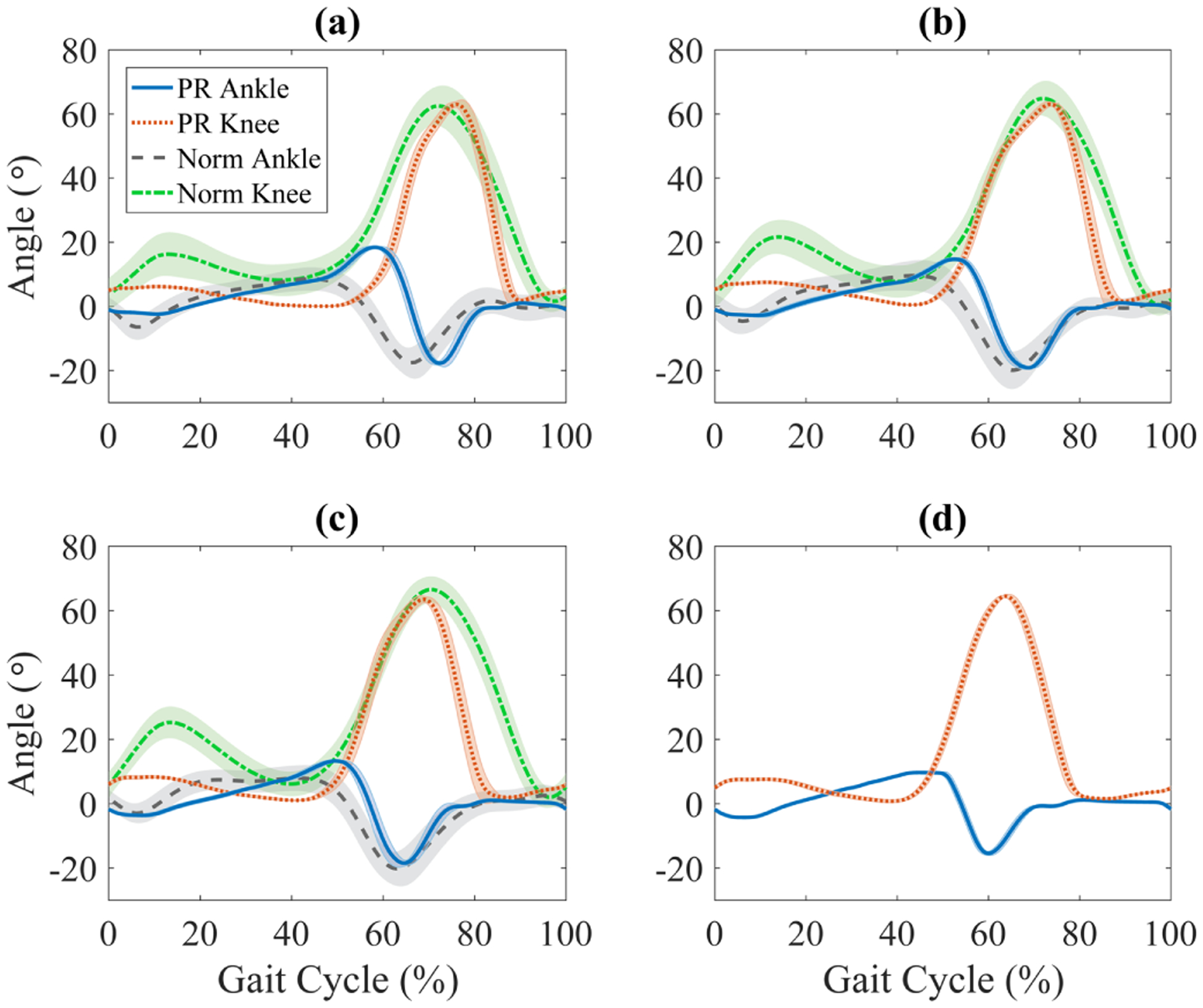
Prosthetic (PR) knee and ankle joint position during able-bodied walking with the prosthesis. Solid blue and dotted red lines correspond to the average ankle and knee joint angles, respectively for speeds: a) 0.9 m/s b) 1.1 m/s c) 1.3 m/s d) 1.6 m/s. Standard deviations (±1) are indicated by shaded regions around the mean. Normative (Norm) knee and ankle trajectories [39] (not available for 1.6 m/s) are shown as a reference in green dash-dotted and gray dashed lines, respectively.
Figs. 17 and 18 depict the commanded versus measured torques of the knee and ankle joints, respectively, during walking experiments. As expected from the results of the benchtop tests, the commanded and measured torques closely match, confirming the hypothesis regarding low actuator impedance and unmodeled dynamics. One notable difference is at peak negative torques in Fig. 18. At this point in gait, the excessively large joint acceleration makes the motor’s inertia contribute more to the unmodeled dynamics of the actuator. However, since the joint’s acceleration is larger than what is seen in healthy gait [39], we expect this discrepancy to be mitigated in future control schemes that better limit the joint’s acceleration to normative values.
Fig. 17.

Average knee commanded and measured torque during able-bodied gait. Solid blue and dotted red lines correspond to the commanded and measured torque, respectively, for speeds: a) 0.9 m/s b) 1.1 m/s c) 1.3 m/s d) 1.6 m/s. Standard deviations (±1) are indicated by shaded regions around the mean.
Fig. 18.

Average ankle commanded and measured torque during able-bodied gait. Solid blue and dotted red lines correspond to the commanded and measured torque, respectively, for speeds: a) 0.9 m/s b) 1.1 m/s c) 1.3 m/s d) 1.6 m/s. Standard deviations (±1) are indicated by shaded regions around the mean.
These biomechanical results demonstrate that the prosthetic leg can indeed perform as intended across walking speeds, and justify removing the torque sensors in the revised leg assembly used for amputee testing in Section IV-D.
2). Power Capabilities:
This section examines the ability of the leg to output sufficient power during walking. Fig. 19 displays the leg’s electrical and mechanical power over the average stride at each speed condition. The combination of the leg’s current, i, and voltage, V, allows for the calculation of the prosthetic leg’s total or consumed electrical power at each instant, PE = i · V. This power is compared against the leg’s total output mechanical power of both joints, PM = τK · ωK + τA ·ωA, where τ is measured joint torque, and ω is measured joint velocity; indices K and A indicate values relating to the knee and ankle joints, respectively. Fig. 19 also displays the individual knee mechanical power (PK = τK · ωK) and ankle mechanical power (PA = τA · ωA).
Fig. 19.

Average power per gait cycle of the prosthetic leg at different walking speeds for the able-bodied subject at a) 0.9 m/s, b) 1.1 m/s, c) 1.3 m/s, and d) 1.6 m/s. Solid blue lines indicate power calculated from measured current and voltage to and from the batteries. Dotted red lines indicate power calculated from measured torque and velocity. Dashed gray and dash-dotted green lines indicate mechanical joint power from measured torque and velocity for the ankle and knee, respectively.
Peak mechanical powers for the knee were 236.7, 192.1, 298.7, and 389.4 W, and the ankle peak mechanical powers were 246.1, 275.4, 294.2, and 371.6 W for 0.9, 1.1, 1.3, and 1.6 m/s, respectively. Peak specific powers (normalized by the subjects mass) were 3.24, 2.63, 4.09, and 5.33 W/kg for the knee, and 3.37, 3.77, 4.03, and 5.09 W/kg for the ankle across speeds.
3). Acoustic Sound Level:
Fig. 20 compares the sound level of the presented prosthetic leg to a previously published leg that utilizes high-impedance actuators [68]. Note that the y-axis scale (dBA) is not linear, but logarithmic. In this figure, the gait cycle begins and ends at ground impact, with the transition from stance to swing occurring at about 60% of the gait cycle. It is evident that the leg with low-impedance actuators is much closer to the sound level of able-bodied walking than the leg with high-impedance actuators. As speed increases, the ambient, able-bodied, and low-impedance leg’s sound levels were generally shifted upward in the figure, which is related to the increased sound of the treadmill. In fact, the difference between able-bodied and the low-impedance actuator’s sound levels were fairly similar across speeds, not considering impact with the ground. Note that due to the low sampling rate of the sound level meter (10 Hz), large changes in sound level readings may look like instantaneous jumps in data, which explains why the values at 0% and 100% do not align for all cases. Interestingly, these instantaneous jumps between endpoints were not seen in the traditional actuation style. This likely due to the large velocities, and therefore increasing sound, of the prosthetic actuators leading up to impact impact. Therefore, we can conclude that since the low-impedance actuators are much quieter than the high-impedance actuators, ground-impacts and ambient sound levels have a greater contribution to the sound level of walking with low impedance actuators.
Fig. 20.

Acoustic sound level during gait at a) 0.9 m/s, b) 1.3 m/s. Solid blue, dotted red, dashed gray, and dash-dotted green lines represents the presented prosthetic leg with low-impedance actuators, a traditional powered prosthetic leg with high-impedance actuators, an able-bodied subject, and ambient sound levels, respectively, during treadmill walking. Ground contact of the prosthetic leg starts at 0% of the gait cycle.
It is evident that the low-impedance actuation is much quieter than the traditional actuation. Specifically, the presented leg is on average 7 dB and 6 dB quieter (including impacts) than that of the conventional powered leg at 0.9 and 1.3 m/s, respectively. If impacts were disregarded, we expect the difference would be much greater.
D. Amputee Walking Results to Assess Clinical Performance
This section presents the results from the amputee experiment to assess clinical performance of the prosthesis without the torque sensors. Specifically, we assess the normality of gait kinematics and the power consumption of the prosthesis during amputee walking conditions.
1). Kinematic Analysis:
Fig. 21 shows the collected knee and ankle joint angles of the prosthesis during TF walking at different speeds, and compares them to healthy (normative) gait kinematics [39]. Although the subject typically preferred that pushoff began earlier in the gait cycle than healthy averages, their joint kinematics resemble that of healthy joints in terms of magnitudes and general trends. Specifically, as speeds increase, pushoff shifts earlier in the gait cycle. Furthermore, the early pushoff resulted in a decreased prosthetic stance phase, and therefore a prolonged prosthetic swing phase, which is common in amputee gait. This resulted in a longer period of knee extension before heel strike. However, this affect was diminished at faster speeds, where the kinematics became more normative.
Fig. 21.

Prosthetic (PR) knee and ankle joint position during amputee walking with the prosthesis. Solid blue and dotted red lines correspond to the average ankle and knee joint angles, respectively for speeds: a) 0.9 m/s b) 1.1 m/s c) 1.3 m/s d) 1.6 m/s. Standard deviations (±1) are indicated by shaded regions around the mean. Normative (Norm) knee and ankle trajectories [39] (not available for 1.6 m/s) are shown as a reference in green dash-dotted and gray dashed lines, respectively.
2). Power & Energy Analysis:
Fig. 22 presents the power of the prosthesis during walking with the TF subject, similar to the AB case in Section IV-C2. Because the torque sensors were removed in the TF case, the power is based upon commanded torque, τ, and measured velocity, ω, where we previously saw that commanded torque is an accurate representation of actual torque. By integrating these curves, electrical and mechanical energies were calculated and presented in Table VI. Positive values in this table indicate produced energy (integral of power greater than zero), whereas negative values indicate regenerated energy (integral of power less than zero). Specifically, , , , and indicate produced knee, regenerated knee, produced ankle, and regenerated ankle mechanical energies, respectively. Furthermore, and indicate the produced and regenerated mechanical energies of the combined joints (i.e., from PM). Note that these two values do not directly equal the sum of the produced or regenerated energies of the individual joints. Instead, they arise from the combined joint mechanical energies of the leg as a whole, which accounts for power sharing between the joints. The total efficiency of the prosthesis is defined as , where and are the produced and regenerated electrical energies, respectively. The numerator accounts for the “output” energy flowing to the battery and environment, and the denominator accounts for the “input” energy flowing from the battery and environment. Note that as speed increases, efficiency also increases. One contributing factor to this was the constant 20 W consumed by the electronics and on-board computer, which has more influence on the efficiency relative to mechanical power during slow walking. Moreover, at slower walking speeds, the motors provide torques at lower velocities, where the electric motor is less efficient due to winding losses.
Fig. 22.

Average power per gait cycle of the prosthetic leg at different walking speeds for the amputee subject at a) 0.9 m/s, b) 1.1 m/s, c) 1.3 m/s, and d) 1.6 m/s. Solid blue lines indicate power calculated from measured current and voltage to and from the batteries. Dotted red lines indicate power calculated from measured torque and velocity. Dashed gray and dash-dotted green lines indicate mechanical joint power from measured torque and velocity for the ankle and knee, respectively.
TABLE VI.
Average energy (J) in joules and efficiency (η) of the leg per gait cycle during amputee walking. Subscripts P and R indicate energy produced and regenerated, respectively. K and A indicate mechanical energy of the knee and ankle joint, respectively. M indicates the combined mechanical energy of both joints. E indicates electrical energy from the battery.
| η (%) | |||||||||
|---|---|---|---|---|---|---|---|---|---|
| 0.9 m/s | 5.9 | −10.4 | 9.5 | −13.8 | 13.0 | −21.8 | 27.4 | −6.7 | 40.1 |
| 1.1 m/s | 7.8 | −15.0 | 7.7 | −12.4 | 9.7 | −21.6 | 21.8 | −7.4 | 39.4 |
| 1.3 m/s | 8.4 | −18.7 | 7.4 | −13.3 | 9.3 | −25.5 | 21.4 | −11.2 | 43.7 |
| 1.6 m/s | 21.3 | −14.4 | 17.8 | −12.5 | 36.8 | −24.6 | 57.6 | −11.4 | 58.7 |
Similar to the AB case, the TF subject shows regions where rapid deceleration of joints cause power regeneration. This is most evident in Fig. 22, between approximately 75% and 80% of the gait cycle. We also see regions where power was being shared between the joints, such as Figs. 22 (a)–(c) between approximately 35% and 45% of the gait cycle, where the ankle mechanical power was negative while knee power was positive. Interestingly, this is also seen in Figs. 22 (a) and (b) at approximately 50% of the gait cycle, which allowed for an ankle mechanical power that was larger than the electrical power to the entire leg. This was caused by the large regenerative power of the knee during the same instance, which reduced the power demand from the batteries.
Both energy sharing and regeneration aid in reducing the average energy consumed per gait cycle. Our new prosthetic leg has an average specific power of 0.14, 0.11, 0.08, and 0.40 W/kg (normalized by the subject’s mass) for 0.9, 1.1, 1.3, and 1.6 m/s, respectively. With the selected batteries, the prosthetic leg can currently operate for 2.82, 3.74, 4.92, and 0.99 hours of continuous walking, or 7301, 10514, 14875, and 3263 prosthetic steps at each respective speed. Note that the total step count for the user would double when considering the intact limb.
V. Discussion
A. Advantages of Design
The main objective of this work was to achieve low-impedance actuation in a powered prosthetic leg and to analyze its performance. Initial benchtop tests concluded that with the motors off, the actuators have sufficiently low impedance, with a backdrive torque of ~1–3 Nm and free swing capability. Other tests demonstrated that even with low-impedance actuators, the prosthesis was still able to provide very large torque (>180 Nm), thus satisfying our torque design goals. Furthermore, by measuring the actuator’s open-loop frequency response (Appendix A), we found the actuator’s inertia to be I = 0.0696 km·m2, which is very close to the estimated inertia from the CAD model, I = 0.0625 km·m2, and is less than the state-of-art leg in [16].
For context and comparison, Table VII presents the estimated reflected inertias of the actuators in several other powered prostheses. Note that in this table, values for reflected inertia only consider the motor rotor inertia and transmission ratio, omitting the inertias of the transmission components (hence the presented actuator’s inertia is reported as 0.0557). This was done for consistency when comparing across actuators, since we do not have access to the CAD models or system identification data for these prostheses. Moreover, when comparing actuators, it is also important to compare torque capabilities since an actuator’s reflected inertia can easily be reduced at the cost of torque. Therefore, Table VII also presents the ratio of continuous (nominal) joint torque to joint reflected inertia, ρ. Larger values of ρ indicate an actuator’s ability to achieve large continuous torques with respect to its reflected inertia.
TABLE VII.
Comparison of inertias, transmission ratios, and joint torque of prosthetic leg actuators.
| Motor | Motor Inertia 10−4 (kg·m2) | Gear Ratio | Rotor Reflected Inertia at the Joint (kg·m2) | Continuous Joint Torque (N·m) | ρ (N·m/kg·m2) | |
|---|---|---|---|---|---|---|
| Low-Impedance Leg | Robodrive ILM 85×26 | 1.1500 | 22:1 | 0.0557 | 57.2 | 1027 |
| UTD Leg 1 - Knee1 [14] | Maxon EC-4 pole 30 | 0.0333 | 360:1 | 0.4316 | 34 | 80 |
| UTD Leg 1 - Ankle1 [14] | Maxon EC-4 pole 30 | 0.0333 | 720:1 | 1.7263 | 69 | 40 |
| VU Leg Gen. 3 - Knee [16] | Maxon EC-4pole 30 | 0.0333 | 176:1 | 0.1032 | 17 | 165 |
| VU Leg Gen. 3 - Ankle [16] | Maxon EC-60 | 1.1950 | 115:1 | 1.5804 | 46 | 29 |
| Open-Source Leg - Knee [25] | T-Motor U8 | 1.3000 | 49.4:1 | 0.3172 | 47 | 148 |
| Open-Source Leg - Ankle1 [25] | T-Motor U8 | 1.3000 | 58.4:1 | 0.4434 | 55 | 125 |
| Ampro [69] | Moog BN34 | 0.0510 | 80:1 | 0.3264 | 34 | 104 |
| CMU Leg [70] | Robodrive ILM 85×13HS | 0.6100 | 50:1 | 0.1525 | 71.5 | 469 |
| Utah AVT Knee1 [24] | Maxon EC-4pole 22 | 0.0089 | 25–375:1 | 0.0006–0.1252 | 1–20 | 1667–0.01 |
| Utah Polycentric Ankle1 [50] | Maxon EC-4pole 30 | 0.0333 | 120–800:1 | 0.0479–2.1312 | 11–76 | 229–36 |
Note that the Utah AVT knee [24] is the only prosthesis which has a larger ρ than that of the presented prosthesis. This is achieved when its actively variable transmission minimizes its reduction ratio, therefore minimizing the reflected inertia of the actuator. However, to do this, the subject must stop and unload the prosthesis for a short period of time while the transmission adjusts, which does not allow for quick switching between low-impedance and high-torque. This is most important during the pushoff phase of gait when the leg requires large torques immediately followed by low impedance, which allows for knee free swing and rapid ankle dorsiflexion for toe clearance. Similarly, the Utah Polycentric Ankle prosthesis [50] has a variable transmission with a minimum reflected inertia (0.0479) at approximately 20° of dorsiflexion, but it has a larger reflected inertia than the presented prosthesis throughout the majority of its range of motion. On the other hand, the presented prosthesis inherently has low impedance, and can switch to high stiffness/torque very quickly, which makes it desirable for pushoff and very suitable for other highly dynamic or extreme tasks. Although it is unrealistic to reduce the joint reflected inertia to that of a human joint, which is considered negligible [39], we were able to achieve a compromise between low reflected inertia and high torque to increase ρ compared to other prostheses. In addition to having the largest constant ρ, and to the best of our knowledge, the presented actuators can produce the largest torque of any self-contained powered prosthesis throughout the literature. The tradeoff in terms of weight is discussed in Section V-B.
Open-loop impedance control tests demonstrated that the effects of unmodeled actuator dynamics are negligible for torques over ~10 Nm. The strong agreement of commanded and measured joint torques during AB walking confirmed this hypothesis during gait. Moreover, the compliant nature of the actuators, coupled with the implementation of human joint impedances, allowed the joints to naturally favor biological reference trajectories during the stance phase of gait. These trends are evident in both the AB and TF walking experiments, indicating the potential for simplifying the tuning process compared to traditional actuation schemes. Although further optimization and tuning would be necessary to more closely match normative trajectories, the presented walking experiments demonstrate the possible reduction in tuning time when human joint impedances are directly implemented.
In addition to accurate impedance control, the actuators maintain the ability to accurately control position. This was first demonstrated in benchtop experiments, where the leg successfully tracked positions for frequencies up to 1.3 Hz with negligible error. As the frequency of the trajectory increases, the first visible discrepancy between desired and actual trajectories in Fig. 12 appears at knee flexion and extension immediately after the touchdown phase. In this region of gait, active position tracking is not strictly required because the function of the knee is to absorb energy, which was achieved through impedance control in walking experiments.
Across all speeds in the AB walking experiments, the prosthetic leg’s knee and ankle angles (PR Knee and PR Ankle) were similar to that of the normative knee and ankle reference trajectories (Norm Knee and Norm Ankle) in Fig. 16. Slight discrepancies were seen at some speeds because the controller utilizes reference trajectories for normal walking speed (1.1 m/s), which explains why joint angles were qualitatively similar to the normative trajectories in Fig. 16 (b). Furthermore, AB walking experiments demonstrated increased peak power capabilities compared to previous design approaches [6], [53], [71]. Specifically, during AB walking experiments, the prosthesis displayed peak joint powers of ~380 W, which is greater than the original design goal and the ~200 W and ~250 W peak power reported in [71] and [72], respectively. Furthermore, the peak power available to each actuator is more than 1 kW, which makes the leg suitable for more extreme tasks. Although the amputee subject exhibited similar pushoff powers at the fastest speed, a different walking style was adopted at slower speeds that resulted in lower pushoff powers than normal (Fig. 22). It is likely that the TF subject’s lack of experience with a powered leg contributed to consistently early transitions into swing when walking at slower speeds (Fig. 21). Additional training and experience may be needed for the TF subject to leave the prosthetic foot on the ground longer, therefore better utilizing the pushoff capabilities.
An interesting ancillary benefit of low-impedance actuators is similar to that of series elastic actuators (SEAs). Although the actuators implemented in the presented leg do not have an elastic element, they do have the ability to store energy. During phases of negative joint work, the generated energy can either be used within the leg’s electrical system, to power the other joint, or to recharge the leg’s batteries. This reduces power consumption and increases the efficiency of the prosthetic leg for an extended battery life. Moreover, the low gear ratio reduces the amount of friction and reflected inertia that the motors have to overcome, thus further increasing the efficiency of the leg. To quantify this, a power analysis of the prosthetic leg was conducted, which revealed a practical design advantage through a reduction in the average required power, compared to previous design approaches [6], [71]. During the TF walking trial, the prosthesis demonstrated an average specific power of 0.4 W/kg per gait cycle at very fast walking speeds (1.6 m/s), which is lower than the 0.98 W/kg and 0.88 W/kg average seen in [71] and [72], respectively. Although we observed even lower specific powers at slower speeds, those cases are not used for comparison because of the lower pushoff powers observed. Nevertheless, the decreased power consumption allows the leg to take between 3263 and 14875 prosthetic steps on a single charge of the selected batteries. These values are more than sufficient for the daily use of an average transfemoral amputee, who takes ~1540 prosthetic steps per day [73]. Moreover, energy analysis shows that the total mechanical energy is close to net-zero, similar to able-bodied walking [39].
Very little is presented throughout the literature on the acoustic sound level of assistive devices [74] and powered prosthetic legs [75]. The acoustic sound level becomes important to consider when attempting to translate this emerging technology to the consumer. Upon investigation, the prosthetic leg with low-impedance actuators was on average 6 dB to 7 dB quieter than a prosthetic leg with conventional actuation (see Fig. 20). In fact, peaks seen in the new actuator’s sound level at the beginning of the gait cycle actually originate from impact with the ground, instead of the leg’s actuators. Since control of foot planting was reduced when walking with a prosthetic leg, which continues to decrease as speeds increase, the jump in sound is likely to be a result of the controller managing the leg at impacts. In comparison to typical household items, the sound level of the high-impedance prosthetic leg is akin to a vacuum cleaner (60 dB to 70 dB at ~1.5 m), which is similar to the 70 dB (at ~1 m) presented in [75]. However, the low-impedance prosthetic leg is akin to a refrigerator or an electric tooth brush (50 dB to 60 dB at ~1.5 m) [76]. Efforts can be made to further reduce the sound level of the prosthesis by enclosing or insulating the actuators, similar to commercial products.
B. Limitations
Concerning the design of the presented prosthetic leg, its weight is the top limiting factor for clinical acceptance. A large portion of the leg’s weight comes from the leg’s structure and electric motors in the actuators. There is a tradeoff between an actuator’s mass and its available power. For example, series elasticity could be used to lower the motor’s power, therefore lowering the motor’s mass. However, the addition of an elastic element (such as a spring) and other structural complexities would likely increase the total mass of the actuator. Low-impedance actuators avoid these components and will continue to get lighter as the torque and power density of motor technology improves over time.
An additional tradeoff is between the motor’s mass and the actuator’s backdrivability. Assuming the length of the motor is constant (which is typically determined by geometrical constraints), the following properties for scaling the motor in the radial direction hold [77]: motor torque , motor inertia , and motor mass mm ∝ rgap, where rgap is the distance from the axis of rotation to the center of the gap between the stator and rotor, or gap radius. Based on these relations, the gear ratio for a fixed joint torque τj = nτm scales with . Then the reflected inertia at the joint will scale as Ij = n2Im ∝ 1/rgap. Furthermore, increasing rgap to achieve a lower reflected inertia typically results in a larger motor mass. On the other hand, the gear ratio is proportional to , which results in a smaller/lighter transmission with reduced friction [77].
Achieving low-impedance actuation resulted in a knee-ankle prosthesis with a mass of 6 kg, which is 1–2 kg heavier than some state-of-art knee-ankle prostheses [16], [25], [78]. Other recent works, such as the lightweight powered prosthetic joints in [11], [20], [24], have achieved a mass of 1–2 kg for a single actuated joint. Although the low-impedance actuation scheme tends to be heavier than other powered prostheses, we believe the added mass is justified through the increased power and torque available to both joints, which produces larger pushoff and ground reaction forces. At the same time, the presented mass of 6 kg is much lighter than the 8.1 kg [79] and 11 kg [70] of other prostheses with similar power/torque ratings. Moreover, exploiting the proprioceptive characteristics of the actuator for detecting ground contact [34] could allow the removal of the load cell at the ankle, thus reducing the leg’s mass by another 0.2 kg.
With the design of the leg now validated, additional amputee trials can conducted to investigate clinical outcomes, such as the actuators’ effect on gait compensations. Specifically, we expect that the increased torque-bandwidth of the actuators will provide greater propulsion and toe clearance, thus reducing hip-hiking, vaulting, and circumduction. Optimizing these outcomes may require additional tuning to reduce the deviation of joint kinematics from normative patterns, which was larger than that reported with some other powered prostheses [18]. Tuning could also improve the pushoff output power at the cost of energy consumption. However, the various scenarios tested in this study suggest the leg will remain efficient as gait properties change.
VI. Conclusion
This paper presented the design and experimental validation of a powered prosthetic leg with high-torque, low-impedance actuators. The system implements high-torque motors coupled with low-reduction transmissions. Low mechanical impedance is an inherent feature of the actuators’ design, resulting in low backdrive torques to move the motors.
Benchtop tests showed that the low-impedance actuators have negligible unmodeled actuator dynamics. This was further confirmed through the implementation of human walking impedances into an impedance-based walking controller, which demonstrated that accurate torque control is achievable without torque feedback. The low-impedance actuators were also able to maintain precise position tracking in both benchtop and walking experiments. The compliant nature of the prosthesis allowed for smooth transitions between the impedance- and position-based portions of the walking controller, such as the transition from high output torques at pushoff to high speeds at toe off. Furthermore, the low-impedance actuators presented practical advantages through reduced power consumption and acoustic sound levels.
Future work will include clinical testing with additional amputees to assess the effect the prosthesis has on gait compensations. Additional design revisions may be made to further simplify and reduce the weight and volume of the leg using light-weight materials, fewer sensors, and smaller electronics. Lastly, this prosthetic leg will be further used as a platform for control prototyping to advance the field of prosthetic leg control.
Supplementary Material
Acknowledgment
The authors thank Yonatan Chatzinoff, David Merz, and Kayla Shepodd for assisting the mechanical design, and Jack Doan, Lukas Zekarias, Parikshit Krishnia, and Hanqi Zhu for their programming and electrical assistance. The authors also thank Leslie Gray for her assistance with the amputee experiment.
This work was supported by the National Institute of Child Health & Human Development of the NIH under Award Number DP2HD080349 and R01HD094772. This work was also supported by NSF Award 1637704 / 1854898. The content is solely the responsibility of the authors and does not necessarily represent the official views of the NIH or the NSF. Robert D. Gregg, IV, Ph.D., holds a Career Award at the Scientific Interface from the Burroughs Wellcome Fund.
Biographies

Toby Elery (S’18) received the B.S., M.S., and Ph.D. degrees in mechanical engineering from The University of Texas at Dallas, Richardson, TX, USA, in 2014, 2017, and 2020, respectively. He is currently a Postdoctoral Researcher with The University of Texas at Dallas. His research interests include design innovation for powered prosthetic legs, orthoses, exoskeletons, and assistive devices.

Siavash Razazadeh (M’ 15) received his B.S. and M.S. from Sharif University of Technology, and his Ph.D. from University of Alberta. Currently, he is an Assistant Professor in the Department of Mechanical and Materials Engineering at University of Denver. Prior to this, he worked as a Research Scientist at the Locomotor Control Systems Laboratory, University of Texas at Dallas, working on design and control of prosthetic legs. Between 2012 and 2015, he worked as Postdoctoral Researcher at Dynamic Robotics Laboratory, Oregon State University on control of ATRIAS, a bipedal robot, for DARPA Robotics Challenge (DRC). His research interests include using fundamental concepts of mechanics for design and control of novel robots and mechanisms.

Christopher Nesler received his B.S. in Mechanical Engineering from Oregon State University in 2014, and his M.S. in Biomedical Engineering from Northwestern University in 2016. He now works as a Research Engineer at the Locomotor Control Systems Laboratory (University of Michigan, formerly University of Texas at Dallas), where he works on design and improvement of various powered lower-limb prostheses and exoskeletons.

Robert D. Gregg (S’08-M’10-SM’16) received the B.S. degree in electrical engineering and computer sciences from the University of California at Berkeley, in 2006, and the M.S. and Ph.D. degrees in electrical and computer engineering from the University of Illinois at Urbana- Champaign, in 2007 and 2010, respectively. He joined the Department of Electrical Engineering and Computer Science, Robotics Institute, University of Michigan, as an Associate Professor, in fall 2019. Prior to joining UM, he was an Assistant Professor with the Departments of Bioengineering and Mechanical Engineering, The University of Texas at Dallas. He was also previously a Research Scientist with the Rehabilitation Institute of Chicago and a Postdoctoral Fellow with Northwestern University. His research interest includes in the control of bipedal locomotion with applications to autonomous and wearable robots.
Appendix A. Parameter Identification
To identify the inertia and damping of the actuator, open-loop frequency response tests were performed with the knee actuator fixed to the benchtop and disconnected from its output/load. Sinusoidal torque commands were directly sent to the motor driver and the actuator’s velocity was recorded. The sinusoidal signal began at a very low frequency, and was incrementally increased to higher frequencies until the test had to be halted due to excessive shaking and vibrations, i.e., 0.1 to 35 Hz. The resulting magnitudes presented in Fig. 23 show a DC offset of 7.6 dB and a cut-off frequency of 6 rad/sec at 4.6 dB (or −3 dB from DC offset). Assuming first-order dynamics of the form
| (4) |
the inertia, I, and damping, b, were identified as 0.0696 kg·m2 and 0.4169 N·m·s/rad, respectively. The frequency response of the system (4) with these values has been plotted over the experimental results in Fig. 23. The strong agreement between the two responses verifies that (4) closely explains the dynamics of the system.
Fig. 23.

Magnitude plot for open-loop frequency response tests. This displays the DC offset and and cutoff frequency used to determine actuator impedance and damping.
Appendix B. Range of Stable Controller Gains for Interaction with a Compliant Environment
Following [55] with the identified actuator parameters, the discrete-time stability margin for the controller can be obtained from the points at which the roots of the characteristic equation 1 + C(z)L*(s) satisfy |z| = 1. Here, C(z) is the discretized PD controller of (1), and L*(s) is the sampled-time version of L(s), the transfer function of the actuator dynamics (4) interacting with the human’s impedance H(s):
| (5) |
where T is the sampling time.
Although stability can be investigated for any passive H(s) in (5), it will result in unnecessarily conservative limitations on the gains. As discussed in [55], considering the human impedance as a limited-stiffness spring provides a more realistic set of conditions for the interaction stability. Since the stiffnesses that human leg joints emulate are typically less than 3000 Nm/rad [80], [81], we performed the stability analysis with three different stiffness values: 100 Nm/rad, 1000 Nm/rad, and 10,000 Nm/rad to cover a range of compliant to rigid interactions. The stability margins are depicted in Fig. 24. The PD gains will be selected with regard to the obtained stable region.
Fig. 24.
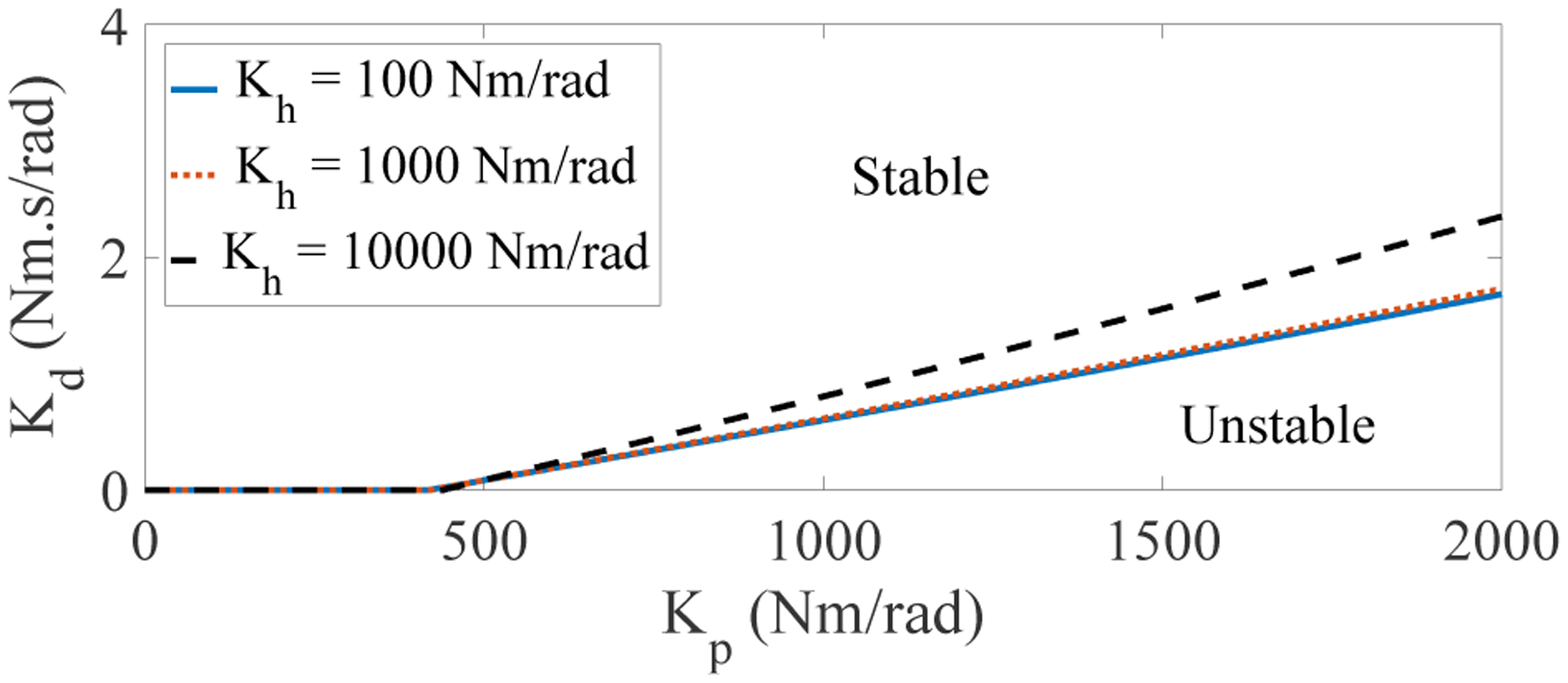
Stability margins for three different human stiffness values, Kh = 100, 1000, and 10,000 Nm/rad. The region above the margins is the stable region.
Note that the stable region obtained in Fig. 24 is still a conservative estimation. This is due to the fact that we did not consider the link inertias in our analysis to avoid nonlinearities, and as discussed in [55], the stable region grows with the increase in inertias. Moreover, we neglected interaction with the ground because the effective joint stiffness of prosthetic feet is much smaller than 10,000 Nm/rad [82], and thus it does not affect our analysis.
Footnotes
Based on estimated average transmission ratios since actual ratios can vary based on joint kinematics.
Note that the load cell was merely used for measurements and not for any kind of feedback control since the control paradigm does not require it. However, future controllers may require its feedback.
References
- [1].Miller W, Deathe A, Speechley M, and Koval J, “The influence of falling, fear of falling, and balance confidence on prosthetic mobility and social activity among individuals with a lower extremity amputation,” Arch. Phys. Med. Rehab, vol. 82, no. 9, pp. 1238–1244, 2001. [DOI] [PubMed] [Google Scholar]
- [2].Gailey RS, Wenger MA, Raya M, Kirk N, Erbs K, Spyropoulos P, and Nash MS, “Energy expenditure of trans-tibial amputees during ambulation at self-selected pace,” Prosthetics Orthotics Int, vol. 18, no. 2, p. 84, 1994. [DOI] [PubMed] [Google Scholar]
- [3].Kaufman KR, Frittoli S, and Frigo CA, “Gait asymmetry of transfemoral amputees using mechanical and microprocessor-controlled prosthetic knees,” Clin. Biomechanics, vol. 27, no. 5, pp. 460–465, 2012. [DOI] [PMC free article] [PubMed] [Google Scholar]
- [4].Lambrecht BG and Kazerooni H, “Design of a semi-active knee prosthesis,” in IEEE Int. Conf. Robot. Automat, 2009, pp. 639–645. [Google Scholar]
- [5].Berry D, “Microprocessor prosthetic knees,” Physical Medicine and Rehabilitation Clinics, vol. 17, no. 1, pp. 91–113, 2006. [DOI] [PubMed] [Google Scholar]
- [6].Pieringer DS, Grimmer M, Russold MF, and Riener R, “Review of the actuators of active knee prostheses and their target design outputs for activities of daily living,” in IEEE Int. Conf. Rehab. Robot, 2017, pp. 1246–1253. [DOI] [PubMed] [Google Scholar]
- [7].Tucker MR, Olivier J, Pagel A, Bleuler H, Bouri M, Lambercy O, del R Millán J, Riener R, Vallery H, and Gassert R, “Control strategies for active lower extremity prosthetics and orthotics: a review,” J. Neuroeng. Rehabil, vol. 12, no. 1, 2015. [DOI] [PMC free article] [PubMed] [Google Scholar]
- [8].Windrich M, Grimmer M, Christ O, Rinderknecht S, and Beckerle P, “Active lower limb prosthetics: a systematic review of design issues and solutions,” Biomed. Eng. Online, vol. 15, no. 3, p. 140, 2016. [DOI] [PMC free article] [PubMed] [Google Scholar]
- [9].Laschowski B and Andrysek J, “Electromechanical design of robotic transfemoral prostheses,” in IEEE Int. Desg. Eng. Tech. Conf. & Info. in Eng. Conf, 2018. [Google Scholar]
- [10].Lenzi T, Sensinger J, Lipsey J, Hargrove L, and Kuiken T, “Design and preliminary testing of the ric hybrid knee prosthesis,” in IEEE Int. Conf. Eng. Med. Biol. Soc IEEE, 2015, pp. 1683–1686. [DOI] [PubMed] [Google Scholar]
- [11].Lenzi T, Cempini M, Hargrove L, and Kuiken T, “Design, development, and validation of a lightweight non-backdrivable robotic ankle prosthesis,” IEEE/ASME Trans. Mechatronics, 2019. [Google Scholar]
- [12].Fu A, Fu C, Wang K, Zhao D, Chen X, and Chen K, “The key parameter selection in design of an active electrical transfemoral prosthesis,” in IEEE Int. Conf. Robotics and Biomimetics IEEE, 2013, pp. 1716–1721. [Google Scholar]
- [13].Yang U-J and Kim J-Y, “Mechanical design of powered prosthetic leg and walking pattern generation based on motion capture data,” Advanced Robotics, vol. 29, no. 16, pp. 1061–1079, 2015. [Google Scholar]
- [14].Quintero D, Villarreal DJ, Lambert DJ, Kapp S, and Gregg RD, “Continuous-phase control of a powered knee–ankle prosthesis: Amputee experiments across speeds and inclines,” IEEE Trans. Robot, vol. 34, no. 3, pp. 686–701, 2018. [DOI] [PMC free article] [PubMed] [Google Scholar]
- [15].Pillai MV, Kazerooni H, and Hurwich A, “Design of a semi-active knee-ankle prosthesis,” in IEEE Int. Conf. Robot. Automat IEEE, 2011, pp. 5293–5300. [Google Scholar]
- [16].Lawson BE, Mitchell J, Truex D, Shultz A, Ledoux E, and Goldfarb M, “A robotic leg prosthesis: Design, control, and implementation,” IEEE Robotics & Automation Magazine, vol. 21, no. 4, pp. 70–81, 2014. [Google Scholar]
- [17].Au SK and Herr H, “Powered ankle-foot prosthesis,” IEEE Robot. Automat. Mag, vol. 15, no. 3, pp. 52–59, 2008. [Google Scholar]
- [18].Sup F, Bohara A, and Goldfarb M, “Design and control of a powered transfemoral prosthesis,” Int. J. Robot. Res, vol. 27, no. 2, pp. 263–273, 2008. [DOI] [PMC free article] [PubMed] [Google Scholar]
- [19].Hoover CD, Fulk GD, and Fite KB, “The design and initial experimental validation of an active myoelectric transfemoral prosthesis,” J. Med. Devices, vol. 6, no. 1, p. 011005, 2012. [Google Scholar]
- [20].Lenzi T, Cempini M, Hargrove L, and Kuiken T, “Design, development, and testing of a lightweight hybrid robotic knee prosthesis,” The Int. J. Robot. Res, vol. 37, no. 8, pp. 953–976, 2018. [Google Scholar]
- [21].Borjian R, Lim J, Khamesee MB, and Melek W, “The design of an intelligent mechanical active prosthetic knee,” in IEEE Conf. Industrial Electronics. IEEE, 2008, pp. 3016–3021. [Google Scholar]
- [22].Kapti AO and Yucenur MS, “Design and control of an active artificial knee joint,” Mechanism and Mach. Theory, vol. 41, no. 12, pp. 1477–1485, 2006. [Google Scholar]
- [23].Liu M, Datseris P, and Huang HH, “A prototype for smart prosthetic legs-analysis and mechanical design,” in Advanced Materials Research, vol. 403 Trans Tech Publ, 2012, pp. 1999–2006. [Google Scholar]
- [24].Tran M, Gabert L, Cempini M, and Lenzi T, “A lightweight, efficient fully-powered knee prosthesis with actively variable transmission,” IEEE Robot. Automat. Letters, 2019. [Google Scholar]
- [25].Azocar AF, Mooney LM, Hargrove LJ, and Rouse EJ, “Design and characterization of an open-source robotic leg prosthesis,” in IEEE Int. Conf. Biomed. Robot. and Biomechatronics, 2018, pp. 111–118. [Google Scholar]
- [26].Seok S, Wang A, Chuah MYM, Hyun DJ, Lee J, Otten DM, Lang JH, and Kim S, “Design principles for energy-efficient legged locomotion and implementation on the mit cheetah robot,” IEEE/ASME Trans. Mechatronics, vol. 20, no. 3, pp. 1117–1129, 2015. [Google Scholar]
- [27].Apgar T, Clary P, Green K, Fern A, and Hurst J, “Fast online trajectory optimization for the bipedal robot cassie,” in Robotics: Science and Syst, Pittsburg, Pennsylvania, 2018. [Google Scholar]
- [28].Kenneally G, De A, and Koditschek DE, “Design principles for a family of direct-drive legged robots,” IEEE Robot. and Automation Letters, vol. 1, no. 2, pp. 900–907, 2016. [Google Scholar]
- [29].Ramos J, Katz B, Chuah MYM, and Kim S, “Facilitating model-based control through software-hardware co-design,” in IEEE Int. Conf. Robot. Automat, 2018. [Google Scholar]
- [30].Lv G, Zhu H, and Gregg R, “On the design and control of highly backdrivable lower-limb exoskeletons,” IEEE Control Syst. Mag, 2018. [DOI] [PMC free article] [PubMed] [Google Scholar]
- [31].Zhu H, Nesler C, Divekar N, Ahmad MT, and Gregg RD, “Design and validation of a partial-assist knee orthosis with compact, backdrivable actuation,” in IEEE Int. Conf. on Rehab. Robot, 2019. [DOI] [PMC free article] [PubMed] [Google Scholar]
- [32].Wang J, Li X, Huang T-H, Yu S, Li Y, Chen T, Carriero A, Oh-Park M, and Su H, “Comfort-centered design of a lightweight and backdrivable knee exoskeleton,” IEEE Robot. Automat. Letters, vol. 3, no. 4, pp. 4265–4272, 2018. [Google Scholar]
- [33].Paine N, Oh S, and Sentis L, “Design and control considerations for high-performance series elastic actuators,” IEEE/ASME Trans. Mechatronics, vol. 19, no. 3, pp. 1080–1091, 2014. [Google Scholar]
- [34].Wensing PM, Wang A, Seok S, Otten D, Lang J, and Kim S, “Proprioceptive actuator design in the mit cheetah: Impact mitigation and high-bandwidth physical interaction for dynamic legged robots,” IEEE Trans. Robot, vol. 33, no. 3, pp. 509–522, 2017. [Google Scholar]
- [35].Simon AM, Ingraham KA, Fey NP, Finucane SB, Lipschutz RD, Young AJ, and Hargrove LJ, “Configuring a powered knee and ankle prosthesis for transfemoral amputees within five specific ambulation modes,” PloS ONE, vol. 9, no. 6, p. e99387, 2014. [DOI] [PMC free article] [PubMed] [Google Scholar]
- [36].Sensinger JW and Lipsey JH, “Cycloid vs. harmonic drives for use in high ratio, single stage robotic transmissions,” in IEEE Int. Conf. Robot. Automat IEEE, 2012, pp. 4130–4135. [Google Scholar]
- [37].Levai Z, “Structure and analysis of planetary gear trains,” J. mechanisms, vol. 3, no. 3, pp. 131–148, 1968. [Google Scholar]
- [38].Elery T, Rezazadeh S, Nesler C, Doan J, Zhu H, and Gregg RD, “Design and benchtop validation of a powered knee-ankle prosthesis with high-torque, low-impedance actuators,” in IEEE Int. Conf. Robot. Automat, 2018. [DOI] [PMC free article] [PubMed] [Google Scholar]
- [39].Winter DA, Biomechanics and Motor Control of Human Movement, 2nd ed New York, NY: Wiley, 2009. [Google Scholar]
- [40].Embry KR, Villarreal DJ, and Gregg RD, “A unified parameterization of human gait across ambulation modes,” in IEEE Eng. Med. Bio. Conf, 2016, pp. 2179–2183. [DOI] [PMC free article] [PubMed] [Google Scholar]
- [41].Ledoux ED and Goldfarb M, “Control and evaluation of a powered transfemoral prosthesis for stair ascent,” IEEE Trans. Neural Syst. and Rehab. Eng, vol. 25, no. 7, pp. 917–924, 2017. [DOI] [PubMed] [Google Scholar]
- [42].Lawson B, Varol H, Huff A, Erdemir E, and Goldfarb M, “Control of stair ascent and descent with a powered transfemoral prosthesis,” IEEE Trans. Neural Sys. Rehab. Eng, vol. 21, no. 3, pp. 466–473, 2013. [DOI] [PubMed] [Google Scholar]
- [43].McDowell MA, Fryar CD, Ogden CL, and Flegal KM, “Anthropometric reference data for children and adults: United states, 2003–2006,” Nat. health statistics reports, vol. 10, no. 1–45, p. 5, 2008. [PubMed] [Google Scholar]
- [44].Gupta V and Deb A, “Analysis of variable gear system on energy consumption in electric vehicle using simulation tool,” IJSSST, vol. 13, no. 2, pp. 7–11, 2012. [Google Scholar]
- [45].Ding Y and Park HW, “Design and experimental implementation of a quasi-direct-drive leg for optimized jumping,” in IEEE/RSJ Int. Conf. Intell. Robots and Syst, 2017, pp. 300–305. [Google Scholar]
- [46].Smidt GL, “Biomechanical analysis of knee flexion and extension,” J. biomechanics, vol. 6, no. 1, pp. 79IN1381–8092, 1973. [DOI] [PubMed] [Google Scholar]
- [47].Pfeifer S, Riener R, and Vallery H, “An actuated transfemoral prosthesis with optimized polycentric knee joint,” in IEEE Int. Conf. Biomed. Robotics and Biomechatronics. IEEE, 2012, pp. 1807–1812. [Google Scholar]
- [48].Census.gov, “Table 205. cumulative percent distribution of population by height and sex: 2007 to 2008”,” 2011. [Online]. Available: https://www2.census.gov/library/publications/2010/compendia/statab/130ed/tables/11s0205.pdf
- [49].Browning RC, Modica JR, Kram R, and Goswami A, “The effects of adding mass to the legs on the energetics and biomechanics of walking,” Medicine & Science in Sports & Exercise, vol. 39, no. 3, pp. 515–525, 2007. [DOI] [PubMed] [Google Scholar]
- [50].Cempini M, Hargrove LJ, and Lenzi T, “Design, development, and bench-top testing of a powered polycentric ankle prosthesis,” in IEEE/RSJ Int. Conf. Intell. Robots and Syst, 2017, pp. 1064–1069. [Google Scholar]
- [51].LaPre AK and Sup F, “Redefining prosthetic ankle mechanics: Non-anthropomorphic ankle design,” in IEEE Int. Conf. Rehab. Robot IEEE, 2013, pp. 1–5. [DOI] [PubMed] [Google Scholar]
- [52].Gregg RD, Lenzi T, Hargrove LJ, and Sensinger JW, “Virtual constraint control of a powered prosthetic leg: From simulation to experiments with transfemoral amputees,” IEEE Trans. Robot, vol. 30, no. 6, pp. 1455–1471, 2014. [DOI] [PMC free article] [PubMed] [Google Scholar]
- [53].Rezazadeh S, Quintero D, Divekar N, and Gregg RD, “A phase variable approach to volitional control of powered knee-ankle prostheses,” in IEEE/RSJ Int. Conf. Intell. Robots and Syst, Madrid, Spain, 2018. [DOI] [PMC free article] [PubMed] [Google Scholar]
- [54].Hogan N, “Impedance control: An approach to manipulation: Part II-Implementation,” J. Dynamic Syst., Meas., and Control, vol. 107, no. 1, pp. 8–16, 1985. [Google Scholar]
- [55].Colgate JE and Schenkel GG, “Passivity of a class of sampled-data systems: Application to haptic interfaces,” J. Robotic Syst, vol. 14, no. 1, pp. 37–47, 1997. [Google Scholar]
- [56].Simon AM, Ingraham KA, Fey NP, Finucane SB, Lipschutz RD, Young AJ, and Hargrove LJ, “Configuring a powered knee and ankle prosthesis for transfemoral amputees within five specific ambulation modes,” PLOS ONE, vol. 9, no. 6, pp. 1–10, 06 2014. [DOI] [PMC free article] [PubMed] [Google Scholar]
- [57].Jindrich DL and Full RJ, “Dynamic stabilization of rapid hexapedal locomotion,” J. Exp. Biology, vol. 205, no. 18, pp. 2803–2823, 2002. [DOI] [PubMed] [Google Scholar]
- [58].Saranli U, Buehler M, and Koditschek DE, “Rhex: A simple and highly mobile hexapod robot,” Int. J. Robot. Res, vol. 20, no. 7, pp. 616–631, 2001. [Google Scholar]
- [59].Rezazadeh S, Abate A, Hatton RL, and Hurst JW, “Robot leg design: A constructive framework,” IEEE Access, vol. 6, no. 1, pp. 54 369–54 387, 2018. [Google Scholar]
- [60].Rezazadeh S, Hubicki C, Jones M, Peekema A, Van Why J, Abate A, and Hurst J, “Spring-mass walking with atrias in 3d: Robust gait control spanning zero to 4.3 kph on a heavily underactuated bipedal robot,” in ASME Dynamic Syst. and Control Conf, Columbus, OH, 2015, p. V001T04A003. [Google Scholar]
- [61].Eilenberg M, Geyer H, and Herr H, “Control of a powered ankle-foot prosthesis based on a neuromuscular model,” IEEE Trans. Neural Sys. Rehab. Eng, vol. 18, no. 2, pp. 164–173, 2010. [DOI] [PubMed] [Google Scholar]
- [62].Shultz AH, Lawson BE, and Goldfarb M, “Variable cadence walking and ground adaptive standing with a powered ankle prosthesis,” IEEE Trans. Neural Syst. and Rehab. Eng, vol. 24, no. 4, pp. 495–505, 2016. [DOI] [PMC free article] [PubMed] [Google Scholar]
- [63].Shamaei K, Sawicki GS, and Dollar AM, “Estimation of quasi-stiffness of the human knee in the stance phase of walking,” PloS one, vol. 8, no. 3, p. e59993, 2013. [DOI] [PMC free article] [PubMed] [Google Scholar]
- [64].——, “Estimation of quasi-stiffness and propulsive work of the human ankle in the stance phase of walking,” PloS one, vol. 8, no. 3, p. e59935, 2013. [DOI] [PMC free article] [PubMed] [Google Scholar]
- [65].Lenzi T, Hargrove L, and Sensinger J, “Speed-adaptation mechanism: Robotic prostheses can actively regulate joint torque,” IEEE Robotics & Automation Magazine, vol. 21, no. 4, pp. 94–107, 2014. [Google Scholar]
- [66].Martin A and Gregg RD, “Stable, robust hybrid zero dynamics control of powered lower-limb prostheses,” IEEE Trans. Automatic Control, vol. 62, no. 8, pp. 3930–3942, 2017. [DOI] [PMC free article] [PubMed] [Google Scholar]
- [67].Satkunskienė D, Grigas V, Eidukynas V, and Domeika A, “Acceleration based evaluation of the human walking and running parameters,” J. Vibroengineering, vol. 11, no. 1, pp. 506–510, 2009. [Google Scholar]
- [68].Quintero D, Villarreal DJ, and Gregg RD, “Preliminary experimental results of a unified controller for a powered knee-ankle prosthetic leg over various walking speeds,” in IEEE Int. Conf. Intelligent Robots Syst, 2016, pp. 5427–5433. [DOI] [PMC free article] [PubMed] [Google Scholar]
- [69].Zhao H, Reher J, Horn J, Paredes V, and Ames AD, “Realization of nonlinear real-time optimization based controllers on self-contained transfemoral prosthesis,” in ACM/IEEE Conf. Cyber-Physical Syst ACM, 2015, pp. 130–138. [Google Scholar]
- [70].Thatte N and Geyer H, “Toward balance recovery with leg prostheses using neuromuscular model control,” IEEE Trans. Biomed. Eng, vol. 63, no. 5, pp. 904–913, 2016. [DOI] [PMC free article] [PubMed] [Google Scholar]
- [71].Lawson BE, Mitchell J, Truex D, Shultz A, Ledoux E, and Goldfarb M, “A robotic leg prosthesis: Design, control, and implementation,” IEEE Robot. & Automation Magazine, vol. 21, no. 4, pp. 70–81, 2014. [Google Scholar]
- [72].Sup F, Varol HA, Mitchell J, Withrow TJ, and Goldfarb M, “Preliminary evaluations of a self-contained anthropomorphic transfemoral prosthesis,” IEEE/ASME Trans. Mechatronics, vol. 14, no. 6, pp. 667–676, 2009. [DOI] [PMC free article] [PubMed] [Google Scholar]
- [73].Halsne EG, Waddingham MG, and Hafner BJ, “Long-term activity in and among persons with transfemoral amputation.” J. Rehabilitation Research & Development, vol. 50, no. 4, 2013. [DOI] [PubMed] [Google Scholar]
- [74].Farris RJ, Quintero HA, and Goldfarb M, “Preliminary evaluation of a powered lower limb orthosis to aid walking in paraplegic individuals,” IEEE Trans. Neural Sys. Rehab. Eng, vol. 19, no. 6, pp. 652–659, 2011. [DOI] [PMC free article] [PubMed] [Google Scholar]
- [75].Sup IV FC, “A powered self-contained knee and ankle prosthesis for near normal gait in transfemoral amputees,” Ph.D. dissertation, Vanderbilt University, 2009. [Google Scholar]
- [76].Company RLC, “dba comparisons.” [Online]. Available: https://www.rlcraigco.com/pdf/dba-comparison.pdf
- [77].Seok S, Wang A, Otten D, and Kim S, “Actuator design for high force proprioceptive control in fast legged locomotion,” in IEEE/RSJ Int. Conf. Intell. Robots and Syst, 2012, pp. 1970–1975. [Google Scholar]
- [78].Rouse EJ, Mooney LM, and Herr HM, “Clutchable series-elastic actuator: Implications for prosthetic knee design,” Int. J. Robot. Res, vol. 33, no. 13, pp. 1611–1625, 2014. [Google Scholar]
- [79].Horn JC, “Design and implementation of the powered self-contained ampro prostheses,” Master’s thesis, Texas A&M University, 2015. [Google Scholar]
- [80].Farley CT, Houdijk HH, Van Strien C, and Louie M, “Mechanism of leg stiffness adjustment for hopping on surfaces of different stiffnesses,” J. Applied Physiology, vol. 85, no. 3, pp. 1044–1055, 1998. [DOI] [PubMed] [Google Scholar]
- [81].Kuitunen S, Ogiso K, and Komi P, “Leg and joint stiffness in human hopping,” Scandinavian J. Medicine & Science in Sports, vol. 21, no. 6, pp. e159–e167, 2011. [DOI] [PubMed] [Google Scholar]
- [82].Adamczyk PG, Roland M, and Hahn ME, “Novel method to evaluate angular stiffness of prosthetic feet from linear compression tests,” J. Biomechanical Engineering, vol. 135, no. 10, p. 104502, 2013. [DOI] [PMC free article] [PubMed] [Google Scholar]
Associated Data
This section collects any data citations, data availability statements, or supplementary materials included in this article.