Abstract
A handheld line-scanned dual-axis confocal (LS-DAC) microscope has been developed for high-speed (16 frames/sec) fluorescence imaging of tissues with sub-nuclear resolution. This is the first miniature fluorescence LS-DAC system that has been fully packaged for handheld clinical use on patients. A novel MEMS-scanning mechanism, with synchronized tilting and pistoning, is used to achieve flat-field en face imaging. We show that this facilitates video mosaicking to generate images that sample an extended lateral field of view.
The microscopic evaluation of slide-mounted tissue specimens on tabletop microscopes remains the “gold standard” for the diagnosis of diseases in clinical practice. However, this method of histopathology is invasive, time-consuming, and introduces imaging artifacts. There is growing interest in developing portable systems for real-time non-invasive microscopic examination of tissues in vivo [1-16]. Many of these devices have been based on scanning confocal microscopy, an optical imaging technique that provides high-resolution cross-sectional images of intact specimens. Conventional confocal microscope systems utilize point-focused illumination and a pinhole at the detector to reject out-of-focus and multiply scattered background light. With point detection, a two-dimensional (2D) scanning mechanism is required to translate the focal point to create a 2D image. However, high speed (kHz range) 2D scanning mechanisms are typically complex and technically challenging to miniaturize, which limits the frame rate of many portable point-scanned confocal systems, resulting in motion artifacts during handheld use. Although confocal endoscopes based on coherent flexible fiber bundle technologies can achieve relatively high frame rates (by scanning the laser focus at the proximal end of the fiber bundle), their spatial resolution is typically inferior to that of non-fiber-bundle-based approaches [17-19].
Dual-axis confocal (DAC) microscopy is an alternative confocal architecture that utilizes spatially separated low-numerical-aperture (NA) beams to achieve effective optical sectioning and superior image contrast in biological tissues [20, 21]. Recently, line-scanned versions of DAC microscopy (LS-DAC) have been shown to enable video-rate imaging with simple low-speed scanners (20-30 Hz), while maintaining comparable image quality to their point-scanned counterparts at depths of up to ~150 μm in tissue [22-24]. Our group previously reported a proof-of-concept miniature LS-DAC design that incorporated a commercial microelectro-mechanical system (MEMS)-based scanning mirror to achieve video-rate confocal imaging [3]. However, the previous system utilized a bulky and expensive tabletop sCMOS (scientific complementary metal oxide semiconductor) camera that was mounted on a precision alignment stage rather than being fully integrated into a portable package. In addition, the scanned imaging field of the proof-of-concept system was curved (rather than an ideal flat 2D plane) due to the geometry of the scanning mechanism, which can result in misleading images especially of thin layered structures.
In this letter, we report the development of the first fully packaged handheld LS-DAC system that utilizes a compact and inexpensive line detector to provide high-speed fluorescence imaging at 16 Hz with sub-nuclear resolution in tissue. Compared to our previous prototype [3], resolution and contrast have been improved, as described in the following paragraph. In addition, to enable flat-field imaging, the device incorporates a novel scanning mechanism in which the MEMS mirror is simultaneously tilted (to scan a 2D image) and pistoned (to compensate for field curvature). We provide examples of en face imaging of layered structures (with and without field curvature), as well as image mosaicking, which is enabled by the flat-field correction. Finally, the entire system has been designed to fit into a standard surgical cart, and is controlled through a user-friendly software interface for real-time imaging by clinicians.
The optical design (Figure 1) of the LS-DAC device is an optimized version of an initial prototype [3]. In the current system, the illumination beam from a 488-nm diode laser (Omicron LuxX 488) is coupled into a custom illumination fiber module (⌀ = 3.2 mm, assembled by Grintech GmbH, Germany) via a single-mode fiber. The illumination module consists of two low-NA doublets (L1, spherical lens, f = 9.0 mm; C, cylindrical lens, f = 12.0 mm), which shape the illumination beam into a line focus with a full-width at half-maximum (FWHM) length of 1.2-mm and a focusing NA of approximately 0.09. This illumination module exhibits improved diffraction-limited focusing with less diffraction side lobes (apodization) compared with our previous system due to the use of a simpler optical layout (two lenses instead of three) and improved fabrication methods (elimination of interior retaining rings that resulted in beam clipping in the previous design). On the collection side, a pair of low-NA spherical doublets (L2, f = 12.0 mm, and L3, f = 60.0 mm) are used to image the focal line with 5X magnification from the back focal plane (BFP) onto the detector array. A 495-nm long-pass filter (Chroma AT495lp) can be inserted along the collection beam path via a quick-release adaptor (Thorlabs QRC05A) to reject back-scattered illumination light. A pair of angled mirrors (fabricated by Tower Optical Inc, FL), with rotational and translational (axial) adjustability, are used to ensure the precise alignment of the illumination and collection foci at a half-crossing angle of 11.0 deg at the BFP of the device. A commercial MEMS scanning mirror (Mirrorcle Technologies, CA) with three degrees of freedom (tip, tilt, and piston) is used to scan the focal line for en face imaging at 16 frames per second (fps), as well as to correct the aforementioned scanning-induced field curvature (described later). All spherical lenses (L1, L2, and L3) were purchased from Edmunds Optics (catalog # 45090, 63692, and 45090, respectively), and were then reduced in diameter by BMV Optical Technologies, Inc. The cylindrical lens, C, was fabricated by BMV based on the design of a spherical doublet from Edmund Optics (catalog # 45262). Finally, a 3X relay objective with a diameter of 14 mm (custom designed by Photon Gear Inc, NY) is used to relay the front focal plane (within the sample) to the BFP with 3X magnification. Since the focusing NAs of both the illumination and collection beams as well as their crossing angles are enhanced by a factor of ~3X, the spatial resolutions of the DAC system are significantly improved at the trade-off of a reduced FOV of approximately 350 μm by 350 μm.
Fig. 1.
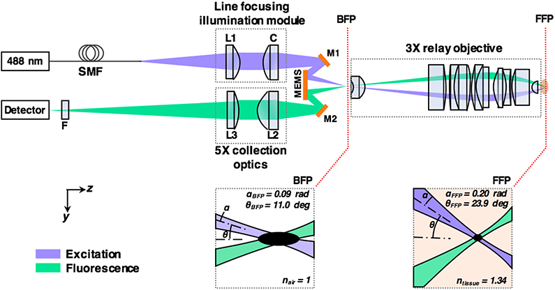
Optical circuit of the handheld LS-DAC microscope. A custom line-focusing fiber module shapes the illumination beam into a focal line at the back focal plane (BFP) of a custom relay objective. A MEMS mirror scans the focal line in one dimension to create an en face 2D image. The objective provides 3X magnification, which boosts the focusing NAs (α) and the half-crossing angles (θ) of the beams from the BFP to the front focal plane (FFP). L1, L2, and L3 are simple low-NA spherical doublets. C is a low-NA cylindrical doublet. M1 and M2 are alignment mirrors. F is a fluorescence filter.
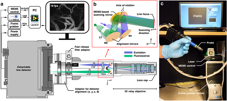
A commercial high-speed CMOS line detector (Basler spL2048-70km) with a pixel spacing of 10 μm is used to sample the focal line at slightly below the Nyquist criterion. Note that the lateral resolution of the system is ~1 μm in the sample, or ~15 μm at the detector plane after magnification by the objective (3x) and collection-path optics (5x). The detector is threaded onto the main body of the device via a custom adaptor that provides a universal SM05-thread interface and four degrees of freedom (x, y, z, and θ) to ensure the precise alignment of the detector (Figure 2). The Basler line detector contains two rows of pixels, which are binned to act as a confocal slit with a width of 20 μm. The line images are then streamed into a high-speed frame grabber (National Instruments PCIe-1473R) at a speed of 125 μs per line via a single camera-link cable. The individual line images are stitched into 2D images (500 lines per image) by the on-board processor of the frame grabber before being transferred to the host PC at 16 fps. A custom LabVIEW-based user interface was developed to display the images in real time and to allow the user to perform basic operations such as zoom, white- and black-level adjustments, video recording, etc.
Fig. 2.
Components of the handheld LS-DAC system. (a) A detachable detector is threaded onto the main body via a custom adaptor that provides four degrees of freedom for precise alignment of the detector. All electronics and optics are connected through quick-release connectorized cables. The modular design allows convenient disassembly for shipping and setup in a clinical setting. (b) A zoomed-in view of the LS-DAC scan head, showing the use of a MEMS mirror to scan a focal line in one direction to achieve high-speed 2D imaging. (c) Photograph showing the setup of the entire system, which can fit into a standard surgical cart.
To correct for scanning-induced curvature, the MEMS mirror is pistoned with a nonlinear waveform to actuate the surface of the mirror in the vertical direction as the mirror tilts to create an en face image (Figure 3). Specifically, based on our preliminary modeling of the mechanically induced field curvature, we determined that an optimal field-flattening waveform would be a rectified sine function Vz = ∣Asin(ωt+ϕ)∣, where Vz is the driving voltage of the MEMS mirror along the z-axis, A is the amplitude of the pistoning motion, ω is the frequency of the actuation, which is identical to the frame rate of the system, and ϕ is used to synchronize the field-flattening waveform to the scanning waveform. Importantly, maximal pistoning is performed at the center of the scan (zero tilt) rather than at the edges of the FOV in order to maintain the full tilting range of the MEMS mirror (+/− 5.5 deg), which thus maintains the FOV of the microscope. Unlike other methods for field flattening [25, 26], our method does not require custom optics or mechanical parts that are difficult to miniaturize, and can be conveniently applied to a high-speed handheld scanning microscope. Note that while this method corrects the curvature at the BFP of the objective, the focal plane of the system (at the FFP of the objective) is also subject to a slight field curvature from the objective lens. The field curvature at the FFP, both before and after flat-field correction, was characterized by acquiring an image stack in which a flat mirror was scanned in the axial (depth) direction using a linear actuator. As shown in Figure 3b, the flatness of the focal surface at the FFP has been corrected to within the axial resolution of the system (< 2 μm).
Fig. 3.
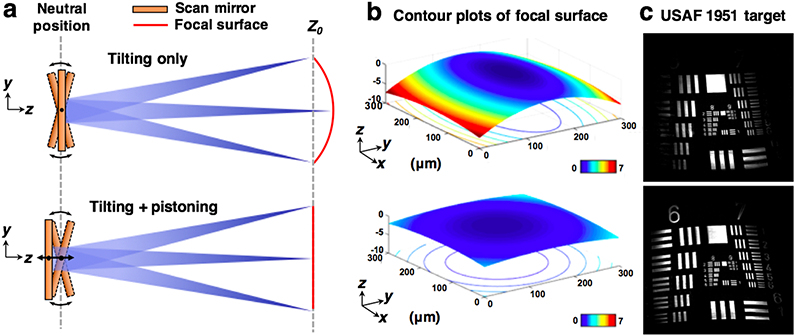
Concept and characterization of MEMS pistoning for flat-field correction. (a) A simplified diagram of the scan head, showing that axial pistoning of the MEMS scanner can counteract the curvature induced by the tilting motion. (b) A contour plot of the focal surface (at the FFP of the objective) showing that the uncorrected field curvature along the y-axis (scan direction) of the FOV is > 7 μm in axial extent, but is reduced to < 2 μm after flat-field correction (which is comparable to the axial resolution of the system). (c) Images of a flat resolution target showing that more of the target is in focus after the flat-field method is applied.
One advantage of a flattened FOV is that it allows more-accurate visualization of thin layered structures. For example, a fresh mouse spleen was stained with 1-mM acridine orange solution for 30 seconds and then rinsed with 1x phosphate buffered saline (PBS, pH 7.4). As shown in Figure 4, the uncorrected system displays a misleading image of the thin mesothelium layer (a cell monolayer) because the image “curves” into the deeper capsule layers (Figure 4 c-d). With flat-field correction, a more-realistic en face image of a continuous mesothelium is generated (Figure 4 f-g).
Fig. 4.
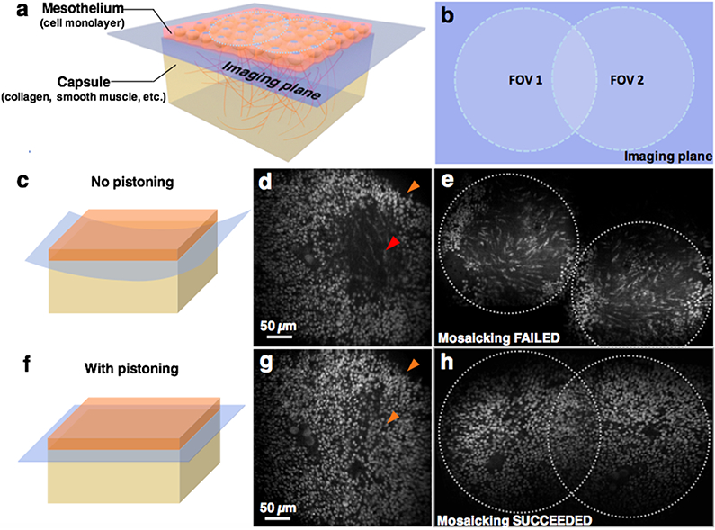
A flattened en face imaging field improves the ability to image thin layered structures as well as to perform image mosaicking. (a) A 3D model showing the structure at the surface of a mouse spleen. (c, d) The uncorrected system does not display a continuous image of the mesothelium monolayer, but rather shows an image that “curves” into the deeper capsule layers. (f, g) With flat-field correction, a more-accurate image of a continuous mesothelium layer is visualized. (b, e, h) The image mosaicking algorithm fails to stitch together two overlapping image frames acquired with the uncorrected system due to poor registration of features, but succeeds after correction.
Another critical advantage of flat-field correction is that it improves image mosaicking of overlapping images in order to create a large-FOV image over time (Figure 4 e, h). As shown in Figure 5, a mosaicked image of a lateral FOV of >2 mm was obtained from a video sequence of fluorescently labelled mouse tissues obtained at 16 fps. Image mosaicking was achieved through post-processing with MosaicJ [27], an open-source image mosaicking plug-in of ImageJ. For tissue imaging, the sample was placed against a glass coverslip that was mounted on a custom disposable lens cap, and the laser power was measured as 1 mW at the tip of the microscope. The gap between the objective lens and the coverslip was filled with ultrasound gel for refractive index matching. All fresh mouse tissues were donated by the Animal Use Training Program at the University of Washington Medical Center for ex vivo use.
Fig. 5.
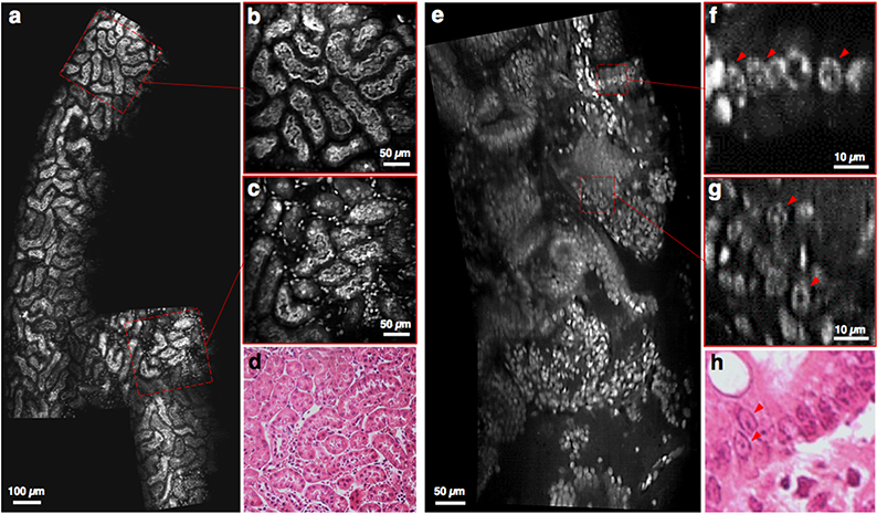
Video mosaicking of fluorescently label fresh mouse tissues imaged at 16 fps (depth of imaging ~50 μm). (a-c) Sub-tubular structures in the cortex of a fresh mouse kidney are clearly visualized, and (d) agree with corresponding H&E histology. (e-g) Another example in a mouse colon shows that sub-nuclear structures are distinguishable, with good agreement with (h) corresponding H&E histology. [See supplemental visualizations for the corresponding video clips]
In summary, we have developed a handheld line-scanned dual-axis confocal (LS-DAC) microscope to provide physicians and other healthcare professionals (e.g. dentists, therapists, etc.) with a real-time and non-invasive alternative to conventional histopathology for the assessment of superficial tissues. Our device is able to achieve a high frame rate of 16 Hz, which minimizes motion artifacts during handheld use, while maintaining excellent image contrast and resolution that can serve as a real-time surrogate for conventional slide-mounted histology. This device is the first fully packaged handheld LS-DAC microscope, in which a portable line-scan detector has been integrated into the device, along with improved illumination optics (better resolution and contrast than a preliminary prototype). We also developed a novel scanning method that utilizes piston-based actuation of a MEMS scanner to correct for the field curvature induced by the tilting motion of the scanner. It should be noted that since the full range of the MEMS scan mirror is utilized to provide maximal FOV and flat-field correction, the mirror cannot provide further depth adjustments without sacrificing the FOV. In the future, threaded or motorized lens caps may be used for fine control of the imaging depth (the current lens cap provides only a fixed imaging depth). We show that flat-field correction enables more accurate en face imaging as well as more effective image mosaicking to sample a large lateral field. In the future, the ability to perform real-time image mosaicking should be of practical value for guiding clinical end users as they strive to sample a large area of tissue. For example, the mosaicks will guide users towards regions that are missed, and will also minimize redundant imaging of other regions. The current system is optimized for imaging fluorescein, a FDA-approved fluorophore that is excited at 488 nm, and has been transferred to the Barrow Neurological Institute (Phoenix, AZ) for an imaging study of human brain tumors. The unique dual-axis confocal architecture and the modular design of our handheld device will enable the conversion of the current system for other applications with minimal modifications, including imaging fluorophores at different wavelengths, or reflectance imaging.
Supplementary Material
Acknowledgments
Funding. The NCI (R01CA175391) and the NIDCR (R01DE023497).
References
- 1.Wang TD; Friedland S; Sahbaie P; Soetikno R; Hsiung PL; Liu JT; Crawford JM; Contag CH, Clin Gastroenterol Hepatol 2007, 5 (11), 1300–5. [DOI] [PMC free article] [PubMed] [Google Scholar]
- 2.Liu JT; Mandella MJ; Loewke NO; Haeberle H; Ra H; Piyawattanametha W; Solgaard O; Kino GS; Contag CH, J Biomed Opt 2010, 15 (2), 026029. [DOI] [PMC free article] [PubMed] [Google Scholar]
- 3.Yin C; Glaser AK; Leigh SY; Chen Y; Wei L; Pillai PC; Rosenberg MC; Abeytunge S; Peterson G; Glazowski C; Sanai N; Mandella MJ; Rajadhyaksha M; Liu JT, Biomed Opt Express 2016, 7 (2), 251–63. [DOI] [PMC free article] [PubMed] [Google Scholar]
- 4.Seibel EJ; Brown CM; Dominitz JA; Kimmey MB, Gastrointest Endosc Clin N Am 2008, 18 (3), 467–78, viii. [DOI] [PMC free article] [PubMed] [Google Scholar]
- 5.Li X; Chudoba C; Ko T; Pitris C; Fujimoto JG, Opt Lett 2000, 25 (20), 1520–2. [DOI] [PubMed] [Google Scholar]
- 6.Carlson K; Chidley M; Sung KB; Descour M; Gillenwater A; Follen M; Richards-Kortum R, Appl Optics 2005, 44 (10), 1792–1797. [DOI] [PubMed] [Google Scholar]
- 7.Liu L; Wang EK; Zhang XY; Liang WX; Li XD; Xie HK, Sensor Actuat a-Phys 2014, 215, 89–95. [DOI] [PMC free article] [PubMed] [Google Scholar]
- 8.Olsovsky C; Hinsdale T; Cuenca R; Cheng YSL; Wright JM; Rees TD; Jo JA; Maitland KC, Journal of Biomedical Optics 2017, 22 (5). [DOI] [PMC free article] [PubMed] [Google Scholar]
- 9.Kumar K; Avritscher R; Wang Y; Lane N; Madoff DC; Yu TK; Uhr JW; Zhang X, Biomed Microdevices 2010, 12 (2), 223–33. [DOI] [PubMed] [Google Scholar]
- 10.Tanbakuchi AA; Rouse AR; Udovich JA; Hatch KD; Gmitro AF, J Biomed Opt 2009, 14 (4), 044030. [DOI] [PMC free article] [PubMed] [Google Scholar]
- 11.Kiesslich R; Burg J; Vieth M; Gnaendiger J; Enders M; Delaney P; Polglase A; McLaren W; Janell D; Thomas S; Nafe B; Galle PR; Neurath MF, Gastroenterology 2004, 127 (3), 706–13. [DOI] [PubMed] [Google Scholar]
- 12.Hoy CL; Durr NJ; Chen P; Piyawattanametha W; Ra H; Solgaard O; Ben-Yakar A, Opt Express 2008, 16 (13), 9996–10005. [DOI] [PMC free article] [PubMed] [Google Scholar]
- 13.Myaing MT; MacDonald DJ; Li X, Opt Lett 2006, 31 (8), 1076–8. [DOI] [PubMed] [Google Scholar]
- 14.Engelbrecht CJ; Johnston RS; Seibel EJ; Helmchen F, Opt Express 2008, 16 (8), 5556–64. [DOI] [PubMed] [Google Scholar]
- 15.Ford TN; Lim D; Mertz J, J Biomed Opt 2012, 17 (2), 021105. [DOI] [PMC free article] [PubMed] [Google Scholar]
- 16.Kyrish M; Dobbs J; Jain S; Wang X; Yu D; Richards-Kortum R; Tkaczyk TS, J Biomed Opt 2013, 18 (9), 096003. [DOI] [PMC free article] [PubMed] [Google Scholar]
- 17.Lee CY; Han JH, Opt Lett 2013, 38 (12), 2023–5. [DOI] [PubMed] [Google Scholar]
- 18.Han JH; Yoon SM, Opt Lett 2011, 36 (16), 3212–4. [DOI] [PubMed] [Google Scholar]
- 19.Kim D; Moon J; Kim M; Yang TD; Kim J; Chung E; Choi W, Opt Lett 2014, 39 (7), 1921–4. [DOI] [PubMed] [Google Scholar]
- 20.Wang TD; Mandella MJ; Contag CH; Kino GS, Opt Lett 2003, 28 (6), 414–6. [DOI] [PMC free article] [PubMed] [Google Scholar]
- 21.Liu JT; Mandella MJ; Friedland S; Soetikno R; Crawford JM; Contag CH; Kino GS; Wang TD, J Biomed Opt 2006, 11 (5), 054019. [DOI] [PMC free article] [PubMed] [Google Scholar]
- 22.Wang D; Chen Y; Wang Y; Liu JT, Opt Lett 2013, 38 (24), 5280–3. [DOI] [PMC free article] [PubMed] [Google Scholar]
- 23.Chen Y; Wang D; Liu JT, Opt Lett 2012, 37 (21), 4495–7. [DOI] [PMC free article] [PubMed] [Google Scholar]
- 24.Chen Y; Wang D; Khan A; Wang Y; Borwege S; Sanai N; Liu JT, J Biomed Opt 2015, 20 (10), 106011. [DOI] [PMC free article] [PubMed] [Google Scholar]
- 25.Walters CT, Appl Opt 1995, 34 (13), 2220–5. [DOI] [PubMed] [Google Scholar]
- 26.Shibuya M f·θ Lens. US4396254A, 1983.
- 27.Thevenaz P; Unser M, Microsc Res Tech 2007, 70 (2), 135–46. [DOI] [PubMed] [Google Scholar]
Associated Data
This section collects any data citations, data availability statements, or supplementary materials included in this article.


