

Abstract
We present an electrodeposition technique for fabricating tubular alginate structures. In this technique, two electrodes (anode and cathode) are suspended in a solution of alginate and insoluble calcium carbonate particles, and the application of an electrical potential produces a localized pH change at the anode surface causing suspended divalent cations to become soluble and cross-link the alginate. We robustly characterize how the fabrication parameters influence the rate of radial deposition on the anode, including deposition time, applied voltage, alginate concentration, type of divalent cation and concentration, and anode diameter. Furthermore, we produce gels with a range of tailorable features, including mechanical properties, dimensions (thick-ness and lumen size), customizable tubular geometries, and radial compositional heterogeneity.
Keywords: multilayered hydrogels, optical coherence tomography, electroaddressing, vessel structures, hydrogel cross-linking
Graphical Abstract
Biomanufacturing in clinical and preclinical research is being advanced by emerging technologies such as 3D printing (i.e., inkjet printing, extrusion, laser deposition), microfluidics, and micromolding.1–4 Currently, a major tissue-engineering challenge is the fabrication of tubular structures (e.g., heart valves and blood vessels). These are key for a number of biomedical applications, including the treatment of vascular- related diseases and generating large in vitro tissue/organ models that require perfusion from macro- and micro- vasculature. Producing self-supporting perfusable structures, with appropriate spatial distribution of cells within the vessel wall, is challenging for many biofabrication technologies.5 Although bioprinting techniques are powerful for their ability to produce 3D architectures of customizable shapes with a variety of bioinks, there is difficulty in fabricating contained negative volumes (e.g., lumen). Recently, state-of-the-art bioprinting has explored the use of coaxial flow extrusion techniques or support materials, in conjunction with layer-by-layer printing of ring shaped structures, to create free-standing tubular gels.6–11 Other recent bioprinting efforts have utilized 3D-printed hydrogel scaffolds that provide an overall structure for printed sacrificial materials (e.g., gelatin channels), which are liquefied and resolved to generate a lumen.12–15 In addition to bioprinting, microfluidic approaches have also been employed to produce vascular channels, because of their ability to effectively mimic microvasculature.16,17 Other nonprinting fabrication methods have utilized casting-based techniques; one such technique relies on cellular compaction around a nonadherent cylindrical tool that can be later removed to produce the lumen.18–20 Despite these advances, high-throughput fabrication of tubular structures remains an ongoing challenge. There are key limitations, such as production of free-standing vessels, from the micro- to meso-size range, with tailorable features (i.e., mechanical properties, lumen size, structure geometry, and compositional heterogeneity), which must be overcome by any new fabrication platform in order to achieve this goal.
Electrodeposition (ED) (sometimes referred to as electro-addressing) is a recently developed method for biological thin film deposition, e.g., alginate and chitosan.21,22 The ED mechanism for forming hydrogels is hypothesized to utilize a localized pH change, actuated via electrolysis, to cause localized cross-linking of the hydrogels. For example, alginate-based ED solubilizes calcium by inducing a pH change at the anode surface, dissociating calcium carbonate. The presence of free calcium ions cross-links alginate locally at the anode surface, depositing alginate gel. Recent work has leveraged alginate based ED to produce size-controlled gels on flat anode surfaces, with masks corresponding to desired shapes.23 Others have developed an ED hybrid bioprinting technique utilizing an automated probe or a light actuated mechanism, to spatially localize or pattern alginate structures.24–26 Furthermore, the ED procedure is reported to be compatible with living cells23,27 and has been recently applied to explore tubular structures.28 Herein, we develop a radial electrodeposition (rED) approach, using a cylindrical electrode immersed in a solution of alginate suspending calcium carbonate particles, to deposit alginate tubular gels. Upon the application of an electrical potential, alginate gels are observed to rapidly form on the anode, and grow radially with deposition time. Within this study, we characterize how key fabrication properties influence the deposition rate, as well as how they can be leveraged to control vessel features such as wall thickness, lumen diameter, and overall mechanical properties. Furthermore, we performed rED with custom-shaped anodes, to assess the potential for producing more sophisticated, tubular geometries, such as a bifurcation, T-junction, and linear tube with bifurcating ends. Last, we explored the ability of a serial electrodeposition approach to fabricate multilayered hydrogel vessels, with radially heterogeneous, striated vessel walls.
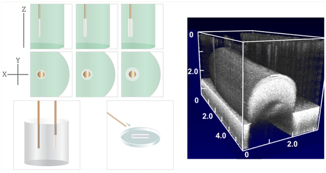
The rED setup (Figure 1) utilizes an electrolysis-based process, wherein two electrodes (e.g., copper cylindrical wires) are submerged within an alginate solution containing insoluble calcium carbonate (CaCO3) particles, dispersed via sonication. The electrodes are in series with a breadboard containing a digital multimeter and an Arduino leading to a DC power supply. In this setup, the voltage is controlled on the power supply, and the Arduino is used as a “trigger” and to determine the total duration of the applied voltage. When the Arduino is triggered, alginate is deposited on the anode surface in a time-dependent manner. Following deposition, the anode is dipped into NaCl to remove any noncrosslinked excess alginate from the probe, then stored in a beaker containing CaCl2 solution.
Figure 1.

Schematic of the radial electrodeposition setup (1), proposed mechanism of gel deposition (2), postdeposition processing and storage (3−4), and stereomicroscope images of electrodes with deposited alginate.
To gain insight into how key fabrication parameters influence the deposition, we created gels over a range of ED parameters including: the applied voltage (electrical potential = 2.7, 5.4, and 10.8 V), alginate concentration (0.5, 1.0, and 2%), calcium carbonate concentration (0.01, 0.1, 0.5, and 1%) and particle size (15–45 nm, 3–5 μm, and 50 μm), type of divalent cation (barium or calcium, BaCO3/CaCO3), and electrode diameter. The rate of gel deposition on the probe was longitudinally characterized during rED fabrication (0–300 s) utilizing optical coherence tomography (OCT), a well-established, label-free, nondestructive imaging modality, with micrometer resolution. We have previously employed OCT for structural and morphologic assessment of 3D cellular aggregates and engineered hydrogels.29,30 To image during rED fabriction, we positioned the OCT probe orthogonally above the anode onto which the alginate was depositing. Single B-scans were captured along the alginate probe at random locations. Differences in optical scattering from refractive index mismatch (between air, alginate, and copper) made alginate gels clearly visible with the OCT modality. Within these scans, we measured the radial distance from the inner to outer diameter of the structure. These measurements were replicated at three random locations along each gel, with three independent gels per condition, and are reported as mean ± standard deviation.
To analyze the effect of these factors on electrodeposition, we fit the time-dependent vessel wall thickness data with logistical curves (Figure S1a–f), to determine the rate of gel deposition (represented as t1/2, time to half of the total wall thickness). These data are summarized in Figure 2a–f as stacked plots of the vessel wall thickness with time, and the corresponding t1/2 value. For example, the effect of applied voltage (2.7, 5.4, 10.8 V) on the rate of alginate deposition is shown in Figure 2a, where the stacked plots of 5.4 and 10.8 V reveal strikingly similar rates of deposition over the first 60 s, and comparable t1/2 values. At later deposition times, vessel wall thickness continued to slowly increase at 10.8 V, while plateauing for 5.4 V. In contrast, at 2.7 V applied voltage, there was consistently lower vessel thicknesses at every time point, and a greater t1/2, illustrating that the lower applied voltage results in a much slower deposition and thinner achievable wall thickness. A consistent finding among all of the gels was that deposition was well described by the logistical curve, including the overall logarithmic shape, and a plateauing effect usually occurring around 1 mm in thickness (Figure S1a–f). This effect is not surprising, considering that as gel thickness increases, so will the resistance in the circuit, which will decrease current (and therefore proton generation). This is also supported by the slower gel deposition at greater alginate concentrations Figure 2b, which is likely a result of a more densely cross-linked gel that causes a greater resistance in the circuit, and reduces the diffusion rate of protons. Overall, we observed that applied voltage, anode diameter, and divalent cation concentration (to some extent) correlated positively with deposition rate (t1/2) and wall thickness. Conversely, we found that alginate concentration correlated inversely with deposition rate. Additionally, particle size, for both CaCO3 and BaCO3, did not appear to have a significant effect on deposition rate.
Figure 2.

Stacked plots of vessel wall thickness with deposition time, and time to reach 50% of wall thickness (t1/2), while manipulating the (a) voltage, (b) alginate concentration, (c) CaCO3 particle size, (d) CaCO3 concentration, (e) BaCO3 concentration, and (f) anode diameter. (g–k) Representative OCT B-scans (x–z cross-section) of alginate deposited on anode during time-course. The dotted red lines indicate the anode and alginate surfaces, and the red arrow in i the vessel wall thickness. Scale bars are 500 μm.
With our ability to control vessel wall thickness established, it was important to explore whether we could also control the lumen size within the tubular structures. We hypothesized that gels produced via rED would conform to the anode, and thus have lumen diameters corresponding to those of the electrode used during fabrication. We utilized three different anode sizes, with diameters 1.00, 0.50, or 0.25 mm, chosen to represent the size of small vessels. Gels were fabricated with each size electrode, imaged with OCT as previously described, and lumen diameters were measured within the ThorLabs software. Measurements were recorded at six random locations within each vessel, with three independent gels fabricated at each anode diameter. Gels made with the 0.25, 0.50, and 1.00 mm anodes (Figure 3b–d) had lumen diameters of 0.26 ± 0.06, 0.53 ± 0.12, and 1.08 ± 0.23 mm, respectively (Figure 3a). This demonstrates the ability of the rED technique to accurately produce tubular structures with precise luminal sizes, over a wide size range, corresponding to electrode diameter. Because of how well the luminal geometries conform to those of the anode, it seems likely that rED could be used to fabricate structures beyond the sizes explored herein.
Figure 3.

Characteristics of rED-fabricated linear vessels: (a) Lumen diameter for corresponding electrode sizes, illustrating that lumen size can be controlled by through the size of the deposition anode. (b–d) B-scans (x–z cross-section) of vessels made with anode diameters 0.25, 0.50, and 1.00 mm; (e) a representative stress–strain curve of an alginate ”ring” specimen in unconfined compression, with the range over which the elastic modulus is determined denoted in red, and (f) elastic modulus values of deposited structures with changing concentration of alginate or (g) divalent cation concentration. Scale bars are 250 μm.
Structural integrity of the constructs is important for this fabrication process, particularly because the gel must be able to withstand removal from the probe following deposition, and be self-supporting to allow for applications involving perfusion. We mechanically characterized the rED-fabricated gels via unconfined uniaxial compression, using a Mach-1 materials testing system (Biomomentum Inc., Laval, QC, Canada). Gel materials test specimens were created by removing fully formed samples from the anode probe, and sectioning them into 2 mm thick cylindrical discs (n = 12) with a central hole, or ”rings”. The dimensions of each test specimen ring (thickness, outer diameter, inner diameter) were measured using OCT, prior to mechanical characterization. The compression platen was then slowly lowered until it made contact with the specimen, utilizing the ”find contact” feature of the system, to establish specimen initial height. From this height, each specimen was uniaxially compressed at a constant rate (0.03 mm/s) to a total compression amplitude of 0.75 mm, while force, displacement and time were recorded. Measured force and displacement data were converted into engineering stress and strain values, respectively, utilizing the individual sample geometries. For each sample, Young’s elastic modulus was approximated by the slope of the linear region of the stress−strain curve, typically occurring between 10 and 20% strain (Figure 3e). Gels were rED-fabricated for every formulation listed in Figure 3f, g and characterized in this manner. We observed that raising the alginate concentration significantly increased the rED-fabricated gel’s reported modulus, and that this could be used to change the mechanical properties 10- to 20-fold; from 1.32 ± 0.5 to 27.8 ± 5.6 kPa and 1.75 ± 0.6 to 23.9 ± 11.2 kPa for either 0.5% CaCO3 or BaCO3, respectively. When controlling for alginate concentration (1%) and manipulating concentration of crosslinker, modulus was observed to have only minor differences within both CaCO3- and BaCO3-fabricated gels. Therefore, it is likely that the majority of the gel’s structural integrity is being produced from the additional cross-linking that occurs after initial fabrication, and prior to mechanical characterization. At most formulation, gels fabricated with barium were significantly stiffer (higher modulus) than their calcium-fabricated counterparts (Figure 3f, g); a finding that is supported by much of the literature.31,32
We next sought to determine whether rED was able to create complex tubular shapes, such as those observed in many lumen-containing structures (e.g., branching vessels, bronchi in the lungs, valves in the heart). To fabricate advanced lumen geometries, we manipulated the shape of the deposition electrode (anode) to create the desired lumen geometry. For example, we utilized straight anodes to produce linear structures (Figure 4bi–ei), and modified anodes to create bifurcated structures (Figure 4bii–eii), T-junctions (Figure 4biii–eiii), and double-bifurcations, i.e., linear strands with bifurcated ends (Figure 4biv–eiv). All structures were rapidly generated (within 5 min), and could be fully visualized with OCT. A video sectioning the gel sample shows the continuous lumen throughout the structure (Videos S1–S4). To our knowledge, no other technique is capable of producing such advanced geometries, particularly in such a rapid time frame.
Figure 4.

(a) Schematic for shape-controlled electrodeposition, and representative images of electrodeposited gels; (b) CCD camera en face images of (i) a linear vessel, (ii) bifurcation, (iii) T-junction, and (iv) double bifurcation , and (c–e) corresponding OCT images taken in (ci–civ) crosssectional, (di–div) en face, and (ei–eiv) volumetric views, illustrating the 3D tubular geometries and continuous internal channel (lumen). All B-scan scale bars are 500 μm.
Beyond customizable geometries, we sought to fabricate structures with differential gel layers, as are often observed within biologic vessels. In this way, it w ould be possible to replicate the different radial tissue layers within physiologic vessels, or create constructs specifically designed for differential drug release. We hypothesized that the rED technique could be performed serially, within different solutions, to produce a striated (or radially heterogeneous) structure (Figure 5a). To test this, we utilized two fluorescently labeled alginate solutions, one labeled with rhodamine (red; emission 575) and the other fluorescein (green; emission 512), and performed a series of 60-s rED fabrications. To perform sequential rED (Figure 5a), (i) a probe is placed in a chosen solution (e.g., green) and a gel is created on the probe via rED; then (ii) the gel-coated probe is moved to a second solution (e.g., red) where rED causes the new gel to form radially on the gel-coated probe; and finally, (iii) the gel-coated anode is placed back in the first solution for a third deposition. These gels were then sectioned into disc-shaped structures and visualized with fluorescent microscopy. Construct cross-sections (Figure 5b–d) clearly show three distinct fluorescent layers (green, red, green), revealing successful creation of striated vessel walls via sequential rED. Although each layer was fabricated using a 60-s deposition, sequential vessel layers show a reduced thickness, which is expected based on the logistic curve for rED with cumulative deposition time (Figure S1). Such fabrication flexibility holds great potential for engineering constructs with radial compositional heterogeneity, for both cellular localization and sequential drug release, as well as for potentially fabricating vessels with radially graded mechanical properties.
Figure 5.

Tubular alginate gels with radial compositional heterogeneity. (a) Schematic for fabricating multilayered alginate tubes by serial electrodeposition. Using fluorescently labeled alginate solutions, a three-layer structure is created by performing an initial rED in one solution (greed), then placing the gel-coated anode into a new solution (red), fabricating a new gel layer on top of the first, and finally returning to the first solution (green) for a final rED layer to produce a green-red-green structure. (b, c) Representative images of a fabricated three-layer structure using labeled alginate (fluorescein (green), rhodamine (red), fluorescein (green)), using a stereomicroscope, and (d) confocal microscopy, illustrating the distinct striations in the construct wall. Note, the high intensity red fluorescence observed on the inner and outer perimeters of the sample in d is an artifact of residual solution on the sample, and not indicative of additional alginate layers. Scale bar is 500 μm.
In summary, we demonstrate the ability of rED to generate vessel structures by initiating alginate cross-linking at an electrode probe during electrolysis. Gelation continues at the anode surface during electrolysis, in a time-dependent manner, which is affected by the various parameters involved in the gelation. This “on demand” process takes place very quickly, over the course of minutes, allowing for rapid-fabrication of tubular structures with controllable lumen size and vessel wall thickness. Furthermore, by manipulating the anode shape, more advanced tubular structures can be created, such as bifurcations, T-junctions, and double bifurcations, and the process can be performed sequentially to create radially striated constructs. Overall, rED provides a relatively simple and cost-effective benchtop method for fabricating shape-controlled engineered vessel structures.
Supplementary Material
ACKNOWLEDGMENTS
This work was supported by the National Institute of Health (NIH) R01 BRG CA20772 (DTC); the RPI Knowledge and Innovation Program (KIP) seed program (DTC); the National Science Foundation (Grant NSF EEC-1559963 and NSF-MRI-1725984).
Footnotes
Supporting Information
The Supporting Information is available free of charge on the ACS Publications website at DOI: 10.1021/acsbiomaterials.9b00415.
Details of the experimental methods used within this work and rate-related deposition data (PDF)
Video S1, optical coherence tomography video of an electrodeposited alginate tube (MP4)
Video S2, optical coherence tomography video of an electrodeposited bifurcation (MP4)
Video S3, optical coherence tomography video of an electrodeposited T-junction (MP4)
Video S4, optical coherence tomography video of an electrodeposited linear tube with bifurcating ends (MP4)
The authors declare no competing financial interest.
REFERENCES
- (1).Murphy SV; Atala A 3D bioprinting of tissues and organs. Nat. Biotechnol 2014, 32, 773–785. [DOI] [PubMed] [Google Scholar]
- (2).Boland T; Xu T; Damon B; Cui X Application of inkjet printing to tissue engineering. Biotechnol. J 2006, 1, 910–917. [DOI] [PubMed] [Google Scholar]
- (3).Dias A; Kingsley D; Corr D Engineering 2D and 3D cellular microenvironments using laser direct-write. 3D Bioprinting and Nanotechnology in Tissue Engineering and Regenerative Medicine 2015, 105–127. [Google Scholar]
- (4).Kingsley D; Dias A; Chrisey D; Corr D Single-step laser-based fabrication and patterning of cell-encapsulated alginate microbeads. Biofabrication 2013, 5, 045006. [DOI] [PMC free article] [PubMed] [Google Scholar]
- (5).Li X; Liu L; Zhang X; Xu T Research and development of 3D printed vasculature constructs. Biofabrication 2018, 10, 032002. [DOI] [PubMed] [Google Scholar]
- (6).Xiong R; Zhang Z; Chai W; Huang Y; Chrisey DB Freeform drop-on-demand laser printing of 3D alginate and cellular constructs. Biofabrication 2015, 7, 045011. [DOI] [PubMed] [Google Scholar]
- (7).Tabriz AG; Hermida MA; Leslie NR; Shu W Threedimensional bioprinting of complex cell laden alginate hydrogel structures. Biofabrication 2015, 7, 045012. [DOI] [PubMed] [Google Scholar]
- (8).Dolati F; Yu Y; Zhang Y; De Jesus AM; Sander EA; Ozbolat IT In vitro evaluation of carbon-nanotube-reinforced bioprintable vascular conduits. Nanotechnology 2014, 25, 145101. [DOI] [PMC free article] [PubMed] [Google Scholar]
- (9).Gao Q; He Y; Fu J.-z.; Liu A; Ma L Coaxial nozzle-assisted 3D bioprinting with built-in microchannels for nutrients delivery. Biomaterials 2015, 61, 203–215. [DOI] [PubMed] [Google Scholar]
- (10).Hinton TJ; Hudson A; Pusch K; Lee A; Feinberg AW 3D printing PDMS elastomer in a hydrophilic support bath via freeform reversible embedding. ACS Biomater. Sci. Eng 2016, 2, 1781–1786. [DOI] [PMC free article] [PubMed] [Google Scholar]
- (11).Christensen K; Xu C; Chai W; Zhang Z; Fu J; Huang Y Freeform inkjet printing of cellular structures with bifurcations. Biotechnol. Bioeng 2015, 112, 1047–1055. [DOI] [PubMed] [Google Scholar]
- (12).Lee VK; Kim DY; Ngo H; Lee Y; Seo L; Yoo S-S; Vincent PA; Dai G Creating perfused functional vascular channels using 3D bio-printing technology. Biomaterials 2014, 35, 8092–8102. [DOI] [PMC free article] [PubMed] [Google Scholar]
- (13).Wüst S; Müller R; Hofmann S 3D B ioprinting of complex channelsâA- fects of material, orientation, geometry, and cell embedding. J. Biomed. Mater. Res., Part A 2015, 103, 2558–2570. [DOI] [PubMed] [Google Scholar]
- (14).Wang X-Y; Jin Z-H; Gan B-W; Lv S-W; Xie M; Huang W-H Engineering interconnected 3D vascular networks in hydrogels using molded sodium alginate lattice as the sacrificial template. Lab Chip 2014, 14, 2709–2716. [DOI] [PubMed] [Google Scholar]
- (15).Bellan LM; Singh SP; Henderson PW; Porri TJ; Craighead HG; Spector JA Fabrication of an artificial 3- dimensional vascular network using sacrificial sugar structures. Soft Matter 2009, 5, 1354–1357. [Google Scholar]
- (16).Sobrino A; Phan DT; Datta R; Wang X; Hachey SJ; Romero-López M; Gratton E; Lee AP; George SC; Hughes CC 3D microtumors in vitro supported by perfused vascular networks. Sci. Rep 2016, 6, 31589. [DOI] [PMC free article] [PubMed] [Google Scholar]
- (17).Schimek K; Busek M; Brincker S; Groth B; Hoffmann S; Lauster R; Lindner G; Lorenz A; Menzel U; Sonntag F; Walles H; et al. Integrating biological vasculature into a multi-organ-chip microsystem. Lab Chip 2013, 13, 3588–3598. [DOI] [PubMed] [Google Scholar]
- (18).Isenberg BC; Williams C; Tranquillo RT Small-diameter artificial arteries engineered in vitro. Circ. Res 2006, 98, 25–35. [DOI] [PubMed] [Google Scholar]
- (19).Ouyang L; Burdick JA; Sun W Facile biofabrication of heterogeneous multilayer tubular hydrogels by fast diffusion-induced gelation. ACS Appl. Mater. Interfaces 2018, 10, 12424–12430. [DOI] [PubMed] [Google Scholar]
- (20).Miller JS; et al. Rapid casting of patterned vascular networks for perfusable engineered three-dimensional tissues. Nat. Mater 2012, 11, 768. [DOI] [PMC free article] [PubMed] [Google Scholar]
- (21).Shi X-W; Tsao C-Y; Yang X; Liu Y; Dykstra P; Rubloff GW; Ghodssi R; Bentley WE; Payne GF Electroaddressing of Cell Populations by Co-Deposition with Calcium Alginate Hydrogels. Adv. Funct. Mater 2009, 19, 2074–2080. [Google Scholar]
- (22).Yi H; Wu L-Q; Bentley WE; Ghodssi R; Rubloff GW; Culver JN; Payne GF Biofabrication with chitosan. Biomacromolecules 2005, 6, 2881–2894. [DOI] [PubMed] [Google Scholar]
- (23).Liu Z; Takeuchi M; Nakajima M; Hasegawa Y; Huang Q; Fukuda T Shape-controlled high cell-density microcapsules by electrodeposition. Acta Biomater. 2016, 37, 93–100. [DOI] [PubMed] [Google Scholar]
- (24).Shang W; Liu Y; Wan W; Hu C; Liu Z; Wong CT; Fukuda T; Shen Y Hybrid 3D printing and electrodeposition approach for controllable 3D alginate hydrogel formation. Biofabrication 2017, 9, 025032. [DOI] [PubMed] [Google Scholar]
- (25).Dai G; Wan W; Zhao Y; Wang Z; Li W; Shi P; Shen Y Controllable 3D alginate hydrogel patterning via visible-light induced electrodeposition. Biofabrication 2016, 8, 025004. [DOI] [PubMed] [Google Scholar]
- (26).Ino K; Matsumoto T; Taira N; Kumagai T; Nashimoto Y; Shiku H Hydrogel electrodeposition based on bipolar electrochemistry. Lab Chip 2018, 18, 2425–2432. [DOI] [PubMed] [Google Scholar]
- (27).Ozawa F; Ino K; Shiku H; Matsue T Electrochemical hydrogel lithography of calcium-alginate hydrogels for cell culture. Materials 2016, 9, 744. [DOI] [PMC free article] [PubMed] [Google Scholar]
- (28).Ozawa F; Ino K; Takahashi Y; Shiku H; Matsue T Electrodeposition of alginate gels for construction of vascular-like structures. J. Biosci. Bioeng 2013, 115, 459–461. [DOI] [PubMed] [Google Scholar]
- (29).Kingsley DM; Roberge CL; Rudkouskaya A; Faulkner DE; Barroso M; Intes X; Corr DT Laser-Based 3D Bioprinting for Spatial and Size Control of Tumor Spheroids and Embryoid Bodies. Acta Biomater. 2019, DOI: 10.1016/j.actbio.2019.02.014. [DOI] [PMC free article] [PubMed] [Google Scholar]
- (30).Faulkner DE; Roberge CE; Kingsley D; Sloat CJ; Corr DT; Intes X Improving Optical Coherence Tomography Contrast for Assessing Biologic Constructs via TiO2. OSA Tech. Dig 2018, No. JTh3A.47. [Google Scholar]
- (31).Mørch ÝA; Donati I; Strand BL; Skjåk-Bræk G Effect of Ca2+, Ba2+, and Sr2+ on alginate microbeads. Biomacromolecules 2006, 7, 1471–1480. [DOI] [PubMed] [Google Scholar]
- (32).Ouwerx C; Velings N; Mestdagh M; Axelos M Physicochemical properties and rheology of alginate gel beads formed with various divalent cations. Polym. Gels Networks 1998, 6, 393–408. [Google Scholar]
Associated Data
This section collects any data citations, data availability statements, or supplementary materials included in this article.