

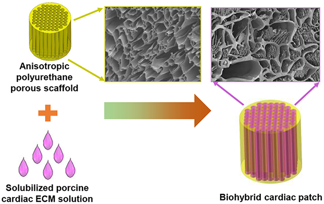
Abstract
Biodegradable cardiac patch is desirable to possess mechanical properties mimicking native myocardium for heart infarction treatment. We fabricated a series of anisotropic and biodegradable polyurethane porous scaffolds via thermally induced phase separation (TIPS) and tailored their mechanical properties by using various polyurethanes with different soft segments and varying polymer concentrations. The uniaxial mechanical properties, suture retention strength, ball-burst strength, and biaxial mechanical properties of the anisotropic porous scaffolds were optimized to mechanically match native myocardium. The optimal anisotropic scaffold had a ball burst strength (20.7 ± 1.5 N) comparable to that of native porcine myocardium (20.4 ± 6.0 N) and showed anisotropic behavior close to biaxial stretching behavior of the native porcine myocardium. Furthermore, the optimized porous scaffold was combined with a porcine myocardium-derived hydrogel to form a biohybrid scaffold. The biohybrid scaffold showed morphologies similar to the decellularized porcine myocardial matrix. This combination did not affect the mechanical properties of the synthetic scaffold alone. After in vivo rat subcutaneous implantation, the biohybrid scaffolds showed minimal immune response and exhibited higher cell penetration than the polyurethane scaffold alone. This biohybrid scaffold with biomimetic mechanics and good tissue compatibility would have great potential to be applied as a biodegradable acellular cardiac patch for myocardial infarction treatment.
Keywords: mechanical match, tissue compatibility, polyurethane, biodegradable, cardiac patch, myocardial infarction
Graphical Abstract
INTRODUCTION
Myocardial infarction (MI) is a leading cause of death of cardiovascular diseases worldwide. Approximately every 40 seconds, an American will have an MI according to the American Heart Association.1 The mean MI mortality rate in poor-performing hospitals (defined as those in the worst quartile of mortality in both 2009 and 2010 for MI) in US was 14.6% in 2015, and that in other hospitals in 2015 was 14.0%.2 As a common end-point of MI, congestive heart failure (CHF) is a life-threatening condition in which the infarcted heart cannot provide sufficient pumping efficiency to meet the body’s needs. Most of current therapies for the CHF, such as medications, biventricular pacing implantation, coronary artery bypass grafting, and valve repair or replacement, have limited applications because they are hard to restore the size or shape of the infarcted heart.3 Heart transplantation is also not the first choice for the patients because of shortage of donors, pulmonary hypertension, chronic organ failure of the recipient, and societal limitations in some parts of the world.4–5 Hence, it is urgent to find alternative strategies to repair infarcted hearts and restore the morphology and function of native myocardium.
Cardiac tissue engineering may be a promising alternative in the past decades. It mainly includes three methods: cell therapy (direct cell injection or cell sheet approach,6–8 engineered cardiac tissue approach (cellularized cardiac patch),9–10 and biomaterials approach (cell-free cardiac patch)11–13. As an optional biomaterial approach, biodegradable and acellular cardiac patches have gained interests and shown promising improvements in cardiac function restoration and heart tissue repair when they are implanted on the infarcted heart surface.14–17 This is because the composition, mechanics and function of cardiac patch can be tailored in vitro and bioactive molecules (e.g., paracrine, growth factors, drugs, etc.) can be encapsulated and released in vivo in a controlled and targeted manner.17 The cardiac patch is desirable to mimic the morphologies of the native myocardium and possess comparable physiological and functional properties to the native heart tissue, such as biocompatibility, biodegradation, bio-absorption at a comparable rate to that of native heart tissue growth, mechanically matching, and high bioactivity to promote cell recruitment, migration, proliferation and differentiation.16, 18–19 Currently, either synthetic biodegradable polymers, such as poly(glycerol sebacate) (PGS),20–21 poly(L-lactide-co-glycolic acid) (PLGA),22–23 poly(glycolide-co-caprolactone (PGCL),24 polycaprolactone (PCL),25–26 and polyurethane,27–29 or natural biomaterials, such as collagen,30–31 alginate,32–33 fibrin,34–35 Matrigel,36 small intestinal submucosa (SIS),37 urinary bladder matrix (UBM)38 and decellularized myocardium matrix11 have been investigated as biodegradable cardiac patches. However, only a few of them have emphasized the significance of mechanical properties. Mechanical mismatch between the biodegradable cardiac patch and the native myocardium may result in abnormal cardiac functions, and eventually leads to implantation failure.39–40 This is because the cells grown on highly rigid cardiac patch will functionalize poorly (e.g., lack of contractile ability) due to dedifferentiation.41–42 Hence, the cardiac patch replacing the infarct heart tissue should be as soft and elastic as the native left ventricle wall. Natural biomaterials generally possess low elastic modulus and low tensile strength, which cannot provide sufficient mechanical support. The stiffness of most of the synthetic polymers is much higher than that of the native heart tissue. Hence, it is important to develop a biodegradable cardiac patch with low initial modulus, appropriate tensile strength and sufficient elasticity.
Biodegradable polyurethanes have been known as elastomeric biomaterials with tunable mechanical properties and good processability, and have been used as cardiac patches for infarcted heart treatment.43–45 But it needs efforts to further tune their mechanical properties to match with the myocardium mechanics through molecular design and scaffold processing. Our group has developed a family of biodegradable elastomeric polyurethanes (PU-PEG-PVCL) synthesized based on a soft segment, a triblock copolymer of poly(ethylene glycol) (PEG) and random copolymers of ε-caprolactone (CL) and δ-valerolactone (VL), which showed low initial moduli (film, 0.9±0.3 to 9.1±0.5 MPa) comparable to the initial moduli of the human myocardium (0.02–0.50 MPa).46 Structure anisotropy is critical for an ideal cardiac patch because of the alignment of elongated cardiomyocytes, the surrounding extracellular matrix and distribution of cell-cell junctions in the native heart muscle, which result in the anisotropy in both action potential propagation and generation of contractile force.47–48 To simulate the anisotropic architecture of native heart muscle, in this work, the synthesized PU-PEG-PVCL polymers were processed into anisotropic porous scaffolds using thermally induced phase separation (TIPS), and their biomechanical properties including ball burst, suture retention, and biaxial mechanics, were optimized to mechanically match the native myocardium by altering polyurethane types and concentrations. To further improve the biocompatibility of the PU-PEG-PVCL anisotropic scaffold, a decellularized and digested porcine myocardium-derived extracellular matrix (ECM) was combined with the PU-PEGPVCL scaffolds to form a biohybrid scaffold. The decellularized heart ECM showed great bioactivity and biofunction in heart infarction treatment in small and large animals.11, 49–51 The morphologies and mechanical properties of the biohybrid scaffolds were characterized with comparison to the PU-PEG-PVCL scaffold alone. A Lewis rat subcutaneous model was used to evaluate the in vivo tissue compatibility and cell infiltration property of the biohybrid scaffold.
MATERIALS AND METHODS
Materials
All chemicals were purchased from Sigma. The VL and hexamethylene diisocyanate (HDI) were distilled for synthesis use. Di(ethylene glycol) (DEG), CL, PEG (molecular weight=1000 and 2000) were dried in a vacuum oven at 60 °C prior to use. Stannous octoate [Sn(Oct)2], putrescine, anhydrous dimethyl sulfoxide (DMSO), sodium dodecyl sulfate (SDS), pepsin, phosphate-buffered saline (PBS), concentrated hydrogen chloride (HCl), sodium hydroxide (NaOH) were used as received.
PU-PEG-PVCL polymer synthesis and anisotropic scaffold fabrication
PU-PEG-PVCL was synthesized according to our previous report.46 Briefly, diblock copolymer diols (PVCL) and triblock copolymer diols (PVCL-PEG-PVCL) were synthesized by ring-opening polymerization based on DEG (an initiator for PVCL) or PEG (an initiator for PVCL-PEG-PVCL), CL and VL (CL:VL molar ratio=50/50). Then, the PU-PEG-PVCL polymers were synthesized from PVCL or PVCL-PEG-PVCL diols (soft segment), hexamethylene diisocyanate (HDI, hard segment) and putrescine (chain extender). The final products were named as PU-PEGx-PVCLy, where x and y are block lengths of PEG and PVCL, respectively.
The anisotropic scaffolds were fabricated via TIPS following a previous protocol (Figure 1).52 PU-PVCL6K, PU-PEG1K-PVCL6K, and PU-PEG2K-PVCL6K polymers were individually dissolved in DMSO at 80 °C to obtain polymer solutions with predetermined concentrations (5%, 8%, and 10%). The polymer/DMSO solution at 80 °C was then poured into a cylinder glass mold with thermal-resistance wrap and then transferred to an −80 °C freezer immediately. After 3 h, the frozen product was placed in deionized water to exchange DMSO for 7 d. The anisotropic scaffold was obtained after lyophilization for further characterization. The obtained scaffolds were recorded as PU-PEG-PVCL-X, where X is the polymer concentration during TIPS process (5%, 8%, and 10%).
Figure 1.
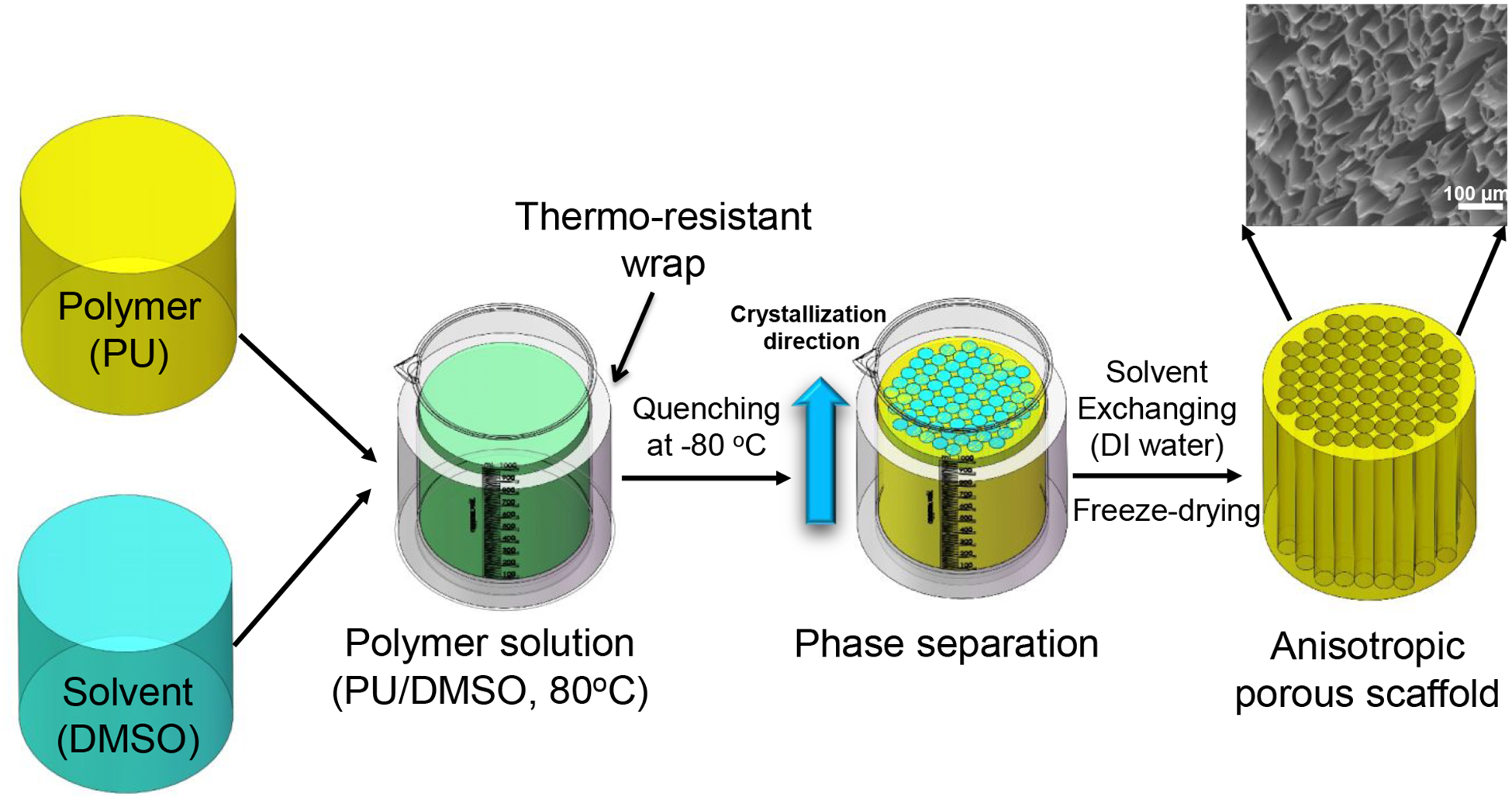
Anisotropic polyurethane porous scaffold fabrication by thermally induced phase separation (TIPS). Polyurethane was thoroughly dissolved in DMSO at 80 °C and then quenched at −80 °C right away. The polymer phase was crystalized, and the solvent phase was solidified. Solvent exchange took place in deionized (DI) water to remove DMSO, followed by lyophilization to obtain anisotropic porous scaffold.
Scaffold characterization
The morphologies of the anisotropic scaffolds were observed by scanning electronic microscope (SEM, Hitachi S-4800 HRSEM) after sputter coating with silver. Pore sizes were determined by the SEM images using ImageJ software (National Institutes of Health, NIH). Porosity of the anisotropic scaffolds (n=3) was determined via ethanol displacement method.52–53
Uniaxial mechanical properties
The uniaxial mechanical properties of the anisotropic scaffolds were measured in longitudinal and transversal directions, respectively, under both dry and wet states. Strips (2×20 mm, n=6) cut from the scaffolds along longitudinal and transversal directions were tested on a MTS Insight Testing System using 500 N loading cell at 10 mm/min under room temperature according to ASTM D638–03.54 The instant recovery (n=3) was measured under the same condition as described above. The two distal ends of the strips were marked, then stretched to 10% strain, held for 1 min and then released. The whole process was repeated for 3 times. The instant recovery was calculated according to the formula [1-(L1-L0)/L0]×100%, where L0 referring to the original length of the strips, and L1 referring to the eventual length right after stretching/releasing for 3 cycles. Cyclic stretching to characterize material elasticity was performed at 30% strain for 10 cycles at 10 mm/min.55 Three samples were tested for each group.
Biomechanical measurement (suture retention, ball burst, and biaxial stretch)
Suture retention strength was measured using a 4–0 silk braided suture (Ethicon, Inc.) under the same condition as the uniaxial mechanical testing.29 One suture loop was threaded through a distal end of a scaffold strip (5×20 mm, n=6) and fixed on an upper clamp. The calculation of the suture retention strength at the point of tearing followed a formula of suture load/(suture diameter × strip thickness).
Ball-burst strength of the anisotropic scaffold (n=4) was assessed by a ball-burst test, following the Standard Test Method for Bursting Strength of Knitted Goods, Constant-Rate-of-Transverse (CRT) Ball-burst Test (ASTM D 3797–89).56–57 The MTS Insight Testing machine was equipped with a ball-burst cage in which a 10 mm polished steel ball was pushed at a constant rate (10 mm/min) against the test material. The ball-burst strength was defined as the force required rupturing the test material when an applied stress is perpendicular to the plane of the material. The porcine native left ventricles were purchased from a local slaughterhouse and excised as a control.
For the biaxial mechanical testing, the principles, setup, and testing protocols of the system were based on a previous design.58 A custom made biaxial mechanical testing system was used to capture the tissue behavior under physiologically-relevant loading conditions. Biaxial testing is well known for its sensitivity to detect tension-stretch (stress-stretch) behavior alterations caused by subtle tissue microstructural changes.59–61 PU-PEG1K-VCL6K-5% and PU-PEG1K-VCL6K-10% (20 mm × 20 mm × 1 mm) were prepared for biaxial mechanical testing, with one axis aligned with the fiber-preferred direction (PD) and the other with the cross-fiber direction (CD) (n=5). Each side of the square sample was mounted onto four stainless steel hooks that are attached to two loops of 000 polyester sutures. Four fiducial graphite markers, affixed to the center of the square sample with cyanoacrylate adhesive, were monitored via a CCD camera to capture the real time stretch ratios. The sample was preconditioned biaxially by imposing 10 cycles of 25 N/m maximum Lagrangian membrane tension.60 After preconditioning, an equibiaxial tension protocol of TCD:TPD = 25:25 N/m was performed to capture the biaxial behavior.
Biohybrid scaffold fabrication and characterization
The decellularized porcine cardiac extracellular matrix (ECM) was prepared and processed into a solubilized ECM solution as previous reports.51, 62 Briefly, intact hearts freshly harvested from adult pigs (weighing 80–100 kg) in a local slaughterhouse were sliced into thin pieces (2-mm in thickness), washed with deionized water and then decellularized in 1% (wt/v) SDS for 3–4 days until the slices became white. The decellularized ECM powder was obtained after lyophilization. The ECM powder was then digested in pepsin/0.01 M HCl solution at room temperature. After 2 days, the digested ECM solution (15 mg/mL) was then neutralization using 0.1 M NaOH and 10X PBS, and then diluted by 1X PBS to reach 10 mg/mL ECM solution. The final solution was sealed and kept in an ice bath until use.
The anisotropic scaffolds were cut into circular patches with 6 mm diameter and 400 μm thickness using standard biopsy punches (6 mm, Miltex) and microtome blade (Thermo Scientific). The patches were sterilized by immersion in 70% ethanol for 1 h, followed by placing in PBS solution to exchange the ethanol for another 1 h. The sterile patches were placed in a 0.22 μm bottle top filter (Corning) connected to a receiving flask.63 The viscous decellularized cardiac ECM solution was added onto the surface of the scaffold patches, and then absorbed into the patches using a low vacuum through the receiving flask. The patch/ECM solution complex was put into a 37 °C incubator for 30 min to allow gelation of the loaded ECM solution to obtain the biohybrid scaffold. The biohybrid scaffolds were named as PU-PEG-PVCL-XH, where H refers to “hybrid”, and X refers to the polymer concentration during TIPS process (5%, 8% and 10%).
The biohybrid scaffold morphology was observed on SEM after lyophilization and silver coating. The uniaxial mechanical properties of the biohybrid scaffold (n=4) were measured in wet state using the same protocol as described above.
Rat subcutaneous implantation
All experimental designs for this animal study was reviewed and approved by the University of Texas at Arlington Animal Care and Use Committee (IACUC) following the National Institutes of Health guidelines for the use of laboratory animals. Both synthetic and biohybrid scaffolds were implanted subcutaneously on the back of Lewis rats. At day 14 and 28, the animals were sacrificed, and the implants and surrounding tissues were isolated for histological analyses (N=4/sample/time point). Tissue sections (10μm thickness) were taken with a Leica Cryostat (CM1850, Leica Microsystem, Wetzlar, Germany) after fixing in OCT embedding medium, frozen, and mounted on glass slides. Multiple tissues from different samples were imaged using light microscopy after hematoxylin-eosin (H&E) staining and studied for cell infiltration assessment.
Statistical analysis
All results are presented as mean ± standard deviation. One-way ANOVA with Tukey-Kramer’s post-hoc test was used to analyze the mechanical properties. p ≤ 0.05 was considered as significant difference.
RESULTS
Scaffold characterization
The anisotropic porous structure of the PU-PEG-PVCL scaffolds was shown in Figure 2. In transversal direction, the scaffolds possessed honeycomb-like pores (Figure 2A, 2C and 2E). In longitudinal direction, aligned pores were observed on the scaffolds (Figure 2B, 2D and 2F). The PU-PVCL6K-5%, PU-PEG1K-PVCL6K-5%, and PU-PEG2K-PVCL6K-5% had pore sizes at 66 ± 26 μm, 91± 57 μm and 123 ± 70 μm, respectively, with porosities of 93% ± 2% to 97% ± 2 % (Table 1).
Figure 2.
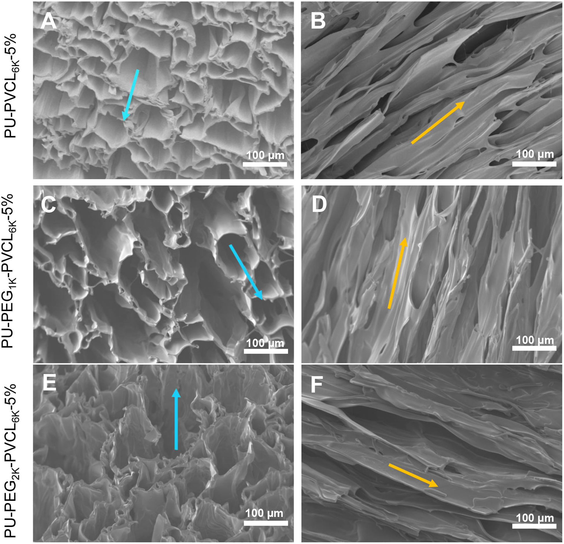
Electron micrographs of anisotropic porous scaffolds prepared from a fixed 5% polymer concentration and various polymers at −80 °C quenching temperature. (A-B) PU-PVCL6K-5% in (A) transversal and (B) longitudinal directions. (C-D) PU-PEG1K-VCL6K-5% in (C) transversal and (D) longitudinal directions. (E-F) PU-PEG2K-VCL6K-5% in (E) transversal and (F) longitudinal directions. Blue arrow shows the transversal direction, and yellow arrow indicates the longitudinal direction.
Table 1.
Anisotropic porous scaffold characterization in dry state.
| Samples | Peak stress (MPa) | Initial modulus (MPa) | Breaking strain (%) | Suture retention (N/mm2) | Instant recovery (%) | Pore size (μm) | Porosity (%) | |||
|---|---|---|---|---|---|---|---|---|---|---|
| L+ | T# | L | T | L | T | |||||
| PU-PVCL6K-5% | 2.3±0.4a | 1.16±0.30a | 2.3±0.6a | 2.53±0.45a | 404±86a | 131±23a | 55±14a | 100±1 | 66±26 | 93±2 |
| PU-PEGIK-PVCL6K-5% | 1.0±0.2b | 0.27±0.04b | 1.3±0.1b | 1.64±0.42b | 445±130a | 51±13b | 27±8b | 100±2 | 91±57 | 96±3 |
| PU-PEG2K-PVCL6K-5% | 0.3±0.1c | 0.13±0.02c | 0.8±0.2c | 0.67±0.30c | 53±18b | 27±6c | 4±1c | 98±1 | 123±70 | 97±2 |
represent longitudinal direction and transversal direction, respectively.
represent significantly different groups for each characteristic.
Scaffold mechanical properties
Mechanical properties of the PU-PVCL6K-5%, PU-PEG1K-PVCL6K-5%, and PU-PEG2K-PVCL6K-5% anisotropic scaffolds in longitudinal and transversal directions under dry and wet states were summarized in Table 1 and Table 2, respectively, and their typical stress-strain curves were shown in Figure S1. In a dry state (Table 1), the peak stresses and initial moduli of the anisotropic scaffolds decreased with increasing soft segment molecular weights of the polyurethanes (p < 0.05). The peak stresses ranged from 0.3 ± 0.1 MPa (PU-PEG2K-PVCL6K-5%) to 2.3 ± 0.4 (PU-PVCL6K-5%) longitudinally, and from 0.13 ± 0.02 MPa (PU-PEG2K-PVCL6K-5%) to 1.16 ± 0.30 (PU-PVCL6K-5%) transversally. The initial moduli were from 0.8 ± 0.2 MPa (PU-PEG2K-PVCL6K-5%) to 2.3 ± 0.6 (PU-PVCL6K-5%) in longitudinal direction, and from 0.67 ± 0.30 MPa (PU-PEG2K-PVCL6K-5%) to 2.53 ± 0.45 (PU-PVCL6K-5%) in transversal direction. The breaking strains also showed the same trends, decreasing from 404 ± 86% (PU-PVCL6K-5%) to 53 ± 18% (PU-PEG2K-PVCL6K-5%) longitudinally, and from 131 ± 23% (PU-PVCL6K-5%) to 27 ± 6% (PU-PEG2K-PVCL6K-5%) transversally. The instant recovery for all anisotropic scaffolds in longitudinal direction was ≥ 98%.
Table 2.
Mechanical properties of anisotropic porous scaffold in wet state
| Samples | Peak stress (MPa) | Initial modulus (MPa) | Breaking strain (%) | |||
|---|---|---|---|---|---|---|
| L+ | T# | L | T | L | T | |
| PU-PVCL6K-5% | 2.30±0.23a | 1.21±0.40a | 1.90±0.24a | 1.92±0.37a | 356±81a | 142±36a |
| PU-PEG1K-PVCL6K-5% | 0.43±0.13b | 0.17±0.01b | 0.56±0.11b | 0.51±0.14b | 246±8a | 61±12b |
| PU-PEG2K-PVCL6K-5% | 0.05±0.02c | 0.03±0.01c | 0.16±0.06c | 0.16±0.07c | 45±8b | 28±6c |
represent longitudinal direction and transversal direction, respectively.
represent significantly different groups for each characteristic.
The incorporation of PEG segment into the polyurethane backbone significantly affected the scaffold mechanical behaviors in a wet state (Table 2). The peak stresses and the initial moduli of the PU-PEG1K-PVCL6K-5%, and PU-PEG2K-PVCL6K-5% anisotropic scaffolds decreased markedly from dry state to wet state (p < 0.05). The peak stresses of the PU-PEG1K-PVCL6K-5% reduced from 1.0 ± 0.2 to 0.43 ± 0.13 MPa longitudinally, and from 0.27 ± 0.04 to 0.17 ± 0.01 MPa transversally. The initial moduli of the PU-PEG1K-PVCL6K-5% decreased from 1.3 ± 0.1 to 0.56 ± 0.11 MPa longitudinally, and from 1.64 ± 0.42 to 0.51 ± 0.14 MPa transversally. However, for the PU-PVCL6K-5% anisotropic scaffold without PEG segment in the polymer chain, there were no significant differences on the peak stress and initial modulus between dry and wet states (p > 0.05).
To evaluate the scaffold dynamic elasticity, the cyclic stretching of the PU-PVCL6K-5%, PU-PEG1K-PVCL6K-5%, and PU-PEG2K-PVCL6K-5% at 30% deformation at longitudinal and transversal directions was performed in the dry and wet states (Figure S2). All the scaffolds exhibited a large hysteresis loop in the first cycle, followed by nine smaller loops. The PU-PVCL6K-5% and PU-PEG1K-PVCL6K-5% exhibited small irreversible deformations (≤ 10%) at two directions in the dry and wet states (Figure S2A, S2B, S2D–S2G, S2I, and S2J). The PU-PEG2K-PVCL6K-5% showed larger permanent deformations (~15%) longitudinally in the dry and wet states (Figure S2C and S2H). The cyclic stretching testing of the PU-PEG2K-PVCL6K-5% scaffold at transversal direction cannot be carried out due to its low breaking strain (27 ± 6 % in dry state and 28 ± 6 % in wet state, transversally).
The suture retention strengths for the PU-PVCL6K-5%, PU-PEG1K-PVCL6K-5%, and PU-PEG2K-PVCL6K-5% anisotropic scaffolds decreased with increasing soft segment molecular weight (p < 0.05) (Table 1). The PU-PVCL6K-5% had the highest suture retention strength at 55 ± 14 N/mm2, and the PU-PEG2K-PVCL6K-5% had the lowest suture retention strength at 4 ± 1 N/mm2.
PU-PEG1K-PVCL6K scaffold characterization and mechanical optimization
The PU-PEG1K-PVCL6K-5%, PU-PEG1K-PVCL6K-8%, and PU-PEG1K-PVCL6K-10% scaffolds had aligned pore structures from transversal (Figure 3A, 3C and 3E) and longitudinal (Figure 3B, 3D and 3F) cross-sections. The average pore sizes and porosities of the PU-PEG1K-PVCL6K scaffolds decreased with increasing polymer concentration (Table 3), although this trend was not statistically significant (p > 0.05). The PU-PEG1K-PVCL6K-5% had the highest average pore size and porosity at 91 μm and 96%, respectively. The PU-PEG1K-PVCL6K-10% had the lowest average pore size and porosity at 51 μm and 90%, respectively.
Figure 3.
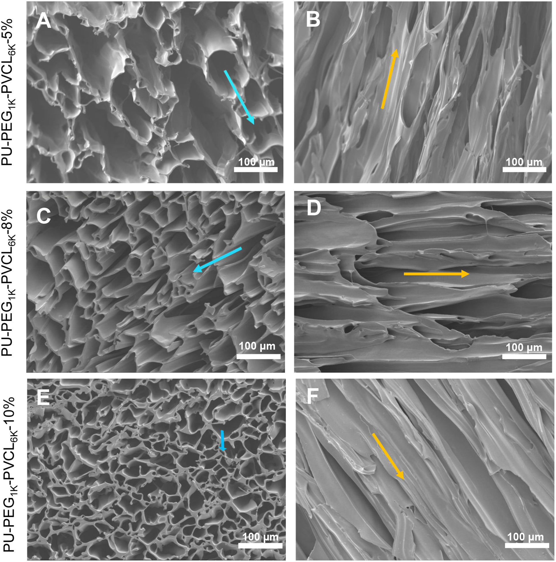
Electron micrographs of PU-PEG1K-PVCL6K anisotropic porous scaffolds prepared from 5%, 8% and 10% polymer concentrations at −80 °C quenching temperature. (A-B) PU-PEG1K-PVCL6K-5% in (A) transversal and (B) longitudinal directions. (C-D) PU-PEG1K-VCL6K-8% in (C) transversal and (D) longitudinal directions. (E-F) PU-PEG1K-VCL6K-10% in (E) transversal and (F) longitudinal directions. Blue arrow shows the transversal direction, and yellow arrow indicates the longitudinal direction.
Table 3.
PU-PEG1K-VCL6K anisotropic porous scaffold characterization in dry state.
| Samples | Peak stress (MPa) | Initial modulus (MPa) | Breaking strain (%) | Instant recovery (%) | Pore size (μm) | Porosity (%) | |||
|---|---|---|---|---|---|---|---|---|---|
| L+ | T# | L | T | L | T | ||||
| PU-PEG1K-PVCL6K-5% | 1.0±0.2a | 0.27±0.04a | 1.3±0.1a | 1.64±0.42a | 445±130a | 51±13a | 99±1 | 91±57 | 96±3a |
| PU-PEG1K-PVCL6K-8% | 1.9±0.2b | 0.60±0.05b | 2.2±0.2b | 1.99±0.33b | 470±80a | 107±23b | 99±1 | 61±34 | 93±1a |
| PU-PEG1K-PVCL6K-10% | 3.1±0.2c | 1.23±0.16c | 3.0±0.3c | 2.60±0.34c | 701±99b | 146±46c | 100±2 | 51±28 | 90±1b |
represent longitudinal direction and transversal direction, respectively.
represent significantly different groups for each characteristic.
The typical stress-strain curves of the scaffolds made from different concentrations in longitudinal and transversal directions in dry and wet states were shown in Figure S3. The scaffold made from higher polymer concentration had greater peak stress, initial modulus and breaking strains at two directions in both dry and wet states (p < 0.05) (Table 3 and Table 4). In the dry state (Table 3), the initial modulus of the scaffold increased from 1.3 ± 0.1 (PU-PEG1K-PVCL6K-5%) to 3.0 ± 0.3 MPa (PU-PEG1K-PVCL6K-10%) longitudinally, and from 1.64 ± 0.42 (PU-PEG1K-PVCL6K-5%) to 2.60 ±0.34 MPa (PU-PEG1K-PVCL6K-10%) transversally. In the wet state (Table 4), the PU-PEG1K-PVCL6K-5% scaffold had the lowest initial moduli at 0.56 ± 0.11 MPa (longitudinally) and 0.61 ± 0.14 MPa (transversally). The PU-PEG1K-PVCL6K-10% had the highest initial moduli at 1.07 ± 0.20 MPa (longitudinally) and 0.91 ± 0.21 MPa (transversally). The instant recoveries for the PU-PEG1K-PVCL6K scaffolds made from 5%, 8% and 10% polymer concentrations in the longitudinal direction were ≥ 99%.
Table 4.
Mechanical properties of PU-PEG1K-VCL6K anisotropic porous scaffold in wet state
| Samples | Peak stress (MPa) | Initial modulus (MPa) | Breaking strain (%) | |||
|---|---|---|---|---|---|---|
| L+ | T# | L | T | L | T | |
| PU-PEG1K-PVCL6K-5% | 0.43±0.13a | 0.17±0.01a | 0.56±0.11a | 0.61±0.14a | 246±88a | 61±12a |
| PU-PEG1K-PVCL6K-8% | 0.56±0.07b | 0.31±0.08b | 0.93±0.22b | 0.85±0.15b | 250±49a | 97±24b |
| PU-PEG1K-PVCL6K-10% | 0.83±0.15c | 0.52±0.11c | 1.07±0.20b | 0.91±0.21b | 344±43b | 121±36c |
represent longitudinal direction and transversal direction, respectively.
represent significantly different groups for each characteristic.
As shown in Figure 4, the PU-PEG1K-PVCL6K-10% scaffold had a ball burst strength at 20.7 ± 1.5 N, which showed no significant difference from the native LV (20.4 ± 6.0 N) (p > 0.05). The PU-PVCL6K-5%, PU-PEG1K-PVCL6K-8%, PU-PEG1K-PVCL6K-5%, and PU-PEG2K-PVCL6K-5% had ball burst strengths at 15.0 ± 2.4 N, 10.5 ± 1.9 N, 7.7 ± 0.6 N and 1.4 ± 0.1 N, respectively, which were statistically lower than that of the native LV (p < 0.05).
Figure 4.
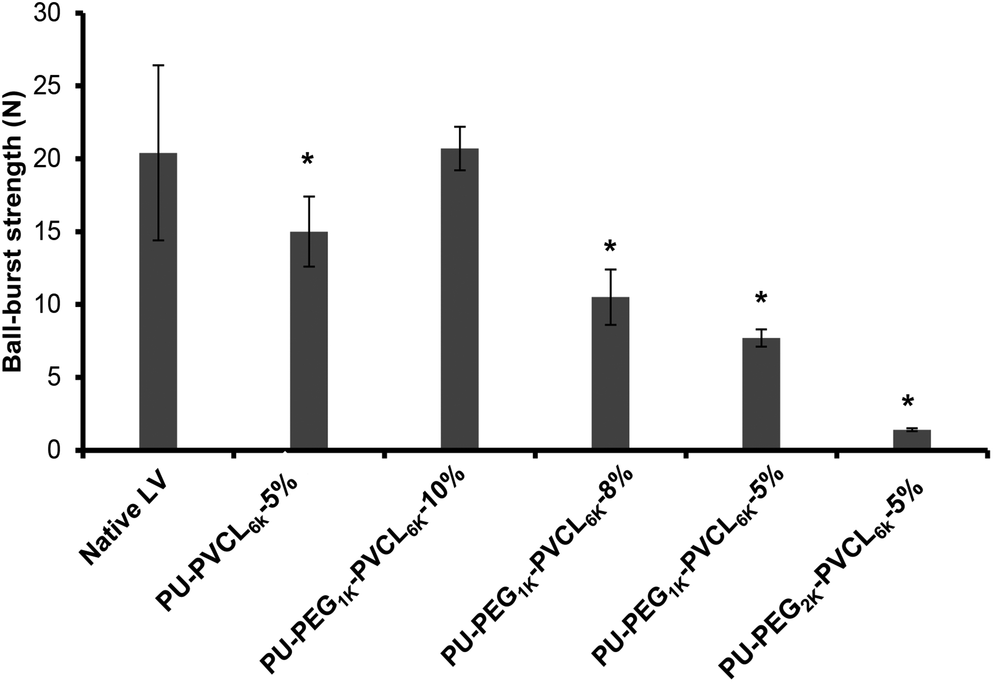
Ball-burst test results for all anisotropic porous scaffolds. Native left ventricle (LV) was used as the control group. * represents significant difference from the native LV group.
The biaxial behavior of PU-PEG1K-PVCL6K-10% scaffolds was evaluated and compared with the biaxial behavior of native porcine myocardium in Figure 5. The overall biaxial behavior of the PU-PEG1K-PVCL6K-10% scaffold F(Figure 5A) was similar to the native myocardium (Figure 5B),60 except that the PU-PEG1K-PVCL6K-10% scaffold was softer than the native myocardium in both PD and CD. Moreover, the degree of anisotropy of the PU-PEG1K-PVCL6K-10% scaffold matched well to that of the native myocardium. Both showed a much stiffer tension-stretch curve along PD and a more extensive tension-stretch curve along CD (Figure 5). It is noted that the PU-PEG1K-PVCL6K-5% was ruptured when the tension reached 15 N/m (data not shown), which reflected its relatively weak mechanical properties.
Figure 5.
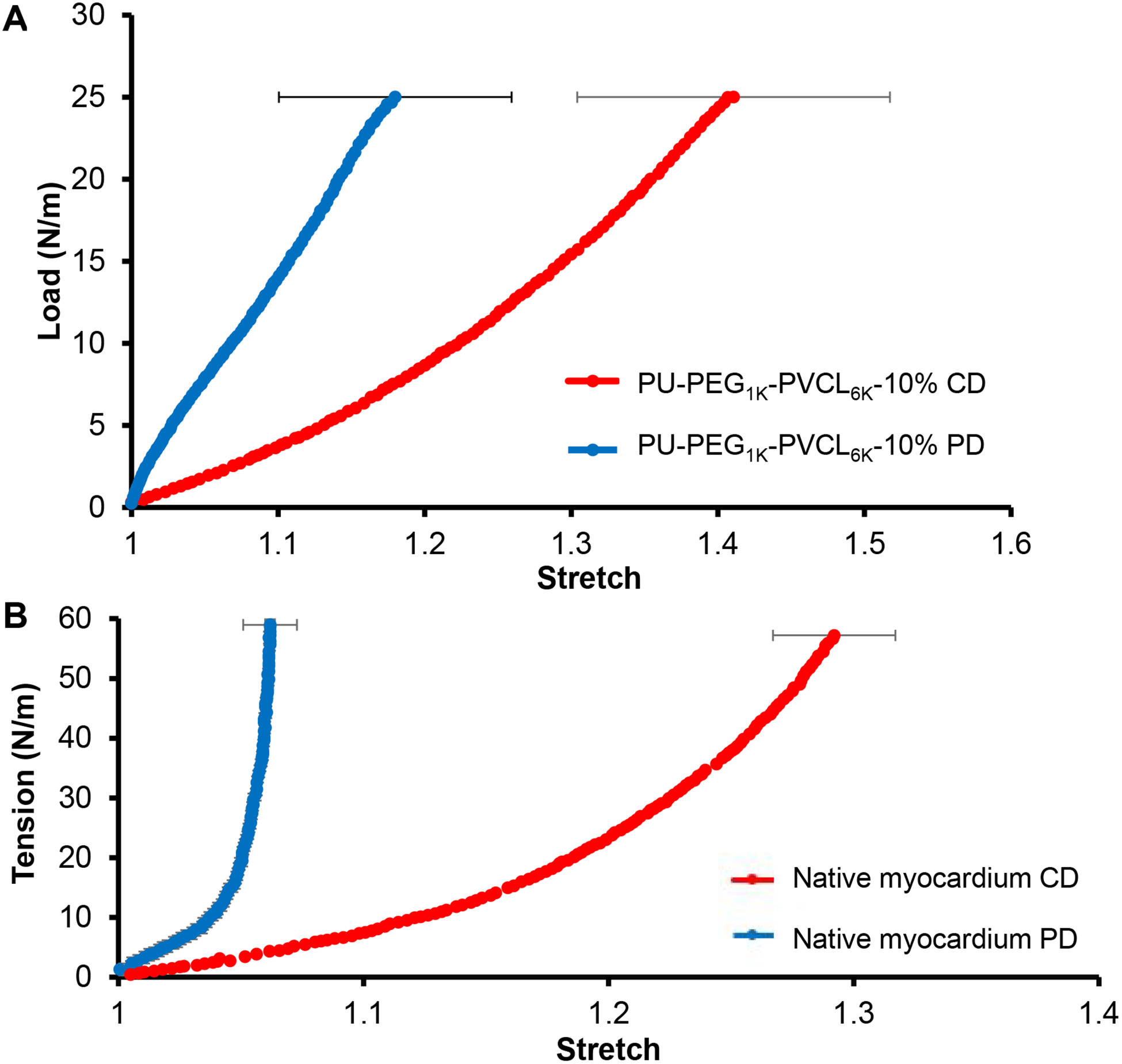
(A) Biaxial testing of PU-PEG1K-PVCL6K-10% in cross-fiber direction (CD) and fiber-preferred direction (PD). (B) Biaxial behavior of porcine native myocardium in cross-fiber direction (CD) and fiber-preferred direction (PD) 60.
Biohybrid scaffold characterization
The biohybrid scaffold fabrication was depicted in Figure 6A and the SEM images of the obtained biohybrid scaffolds showed the fibrous myocardium ECM distributed on the surface and inside their aligned pores (Figure 6B–6J). The mechanical properties of the biohybrid scaffolds in the wet state were listed in Table 5. There was no significant difference between the biohybrid scaffold (Table 5) and its corresponding synthetic scaffold (Table 4) on peak stress, initial modulus and breaking strain (p > 0.05).
Figure 6.
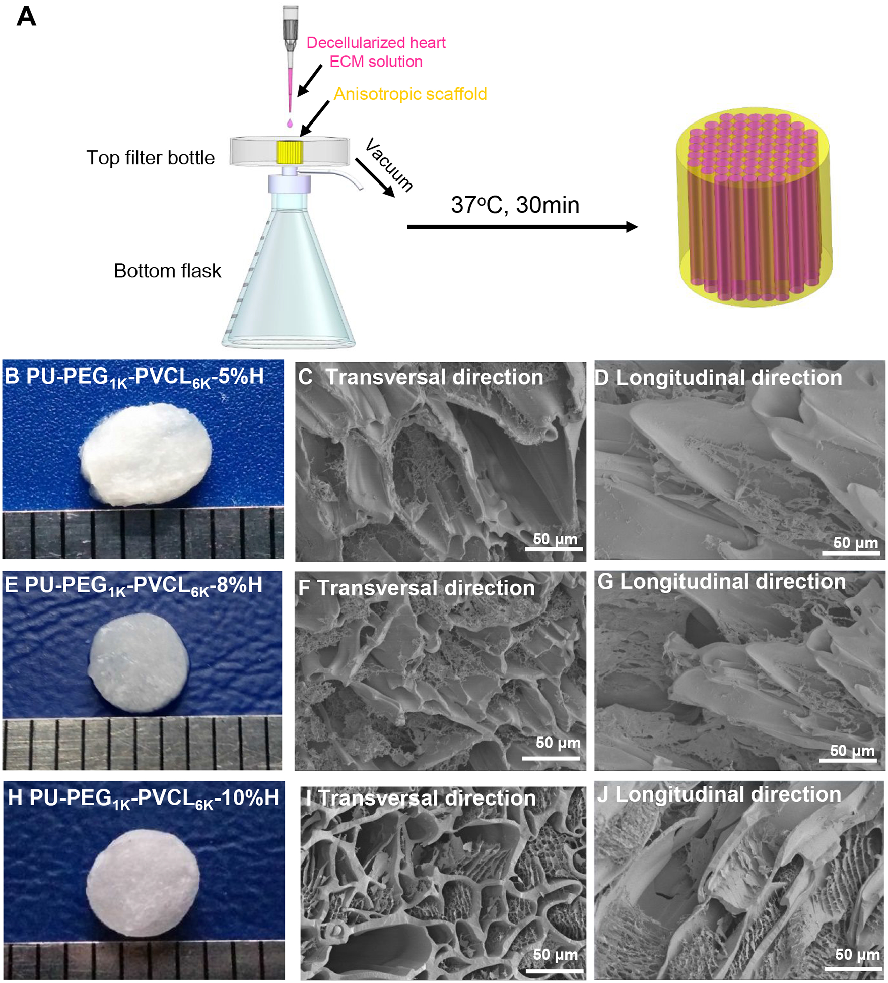
Biohybrid scaffolds fabricated by combining PU-PEG1K-PVCL6K anisotropic scaffolds (5%, 8% and 10% w/v) with myocardium-derived hydrogel. (A) Decellularized heart ECM solution was added dropwise onto the synthetic anisotropic scaffold, and then absorbed into the scaffold by low vacuum. After placing the ECM/scaffold complex at 37 °C for 30 min, the biohybrid scaffold was formed. (B), (E) and (H) Digital images of PU-PEG1K-PVCL6K-5%H, PU-PEG1KPVCL6K-8%H and PU-PEG1K-PVCL6K-10%H. (C), (F), and (I) electron micrographs of PU-PEG1K-PVCL6K-5%H, PU-PEG1K-PVCL6K-8%H and PU-PEG1K-PVCL6K-10%H biohybrid scaffolds in transversal direction. (D), (G), and (J) electron micrographs of PU-PEG1K-PVCL6K-5%H, PU-PEG1K-PVCL6K-8%H and PU-PEG1K-PVCL6K-10%H biohybrid scaffolds in longitudinal direction.
Table 5.
Mechanical properties of biohybrid scaffolds
| Samples | Peak stress (MPa) | Initial modulus (MPa) | Breaking strain (%) | |||
|---|---|---|---|---|---|---|
| L+ | T# | L | T | L | T | |
| PU-PEG1K-PVCL6K-5%H | 0.36±0.05a | 0.19±0.02a | 0.64±0.11a | 0.60±0.15a | 255±33a | 66±15a |
| PU-PEG1K-PVCL6K-8%H | 0.62±0.05b | 0.35±0.05b | 0.85±0.19a,b | 0.78±0.17b | 276±32a | 88±27a |
| PU-PEG1K-PVCL6K-10%H | 0.78±0.10c | 0.56±0.08c | 1.08±0.14b | 0.85±0.20b | 363±52c | 132±25c |
represent longitudinal direction and transversal direction, respectively.
represent significantly different groups for each characteristic.
Rat subcutaneous implantation
The in vivo cell infiltration and tissue compatibility of anisotropic synthetic (PU-PEG1K-PVCL6K-10%) and biohybrid scaffolds (PU-PEG1K-PVCL6K-10%H) were evaluated using subcutaneous implantation model for 2 and 4 weeks. Weak inflammation responses accompanied with small numbers of inflammatory cells were observed in both synthetic and hybrid scaffolds at week 2 (Figure 7A). We have also observed the presence of many cells in both groups of scaffolds. Furthermore, biohybrid scaffolds attracted slightly more cells than synthetic scaffolds at time points based on H&E staining (Figure 7A). The average numbers of infiltrated cells per mm2 were ~20.8±2.0 (synthetic, 2wks), 34.4±5.5 (synthetic, 4wks), 29.2±5.0 (biohybrid, 2wks), and 45.3±8.9 (biohybrid, 4wks). To compare both scaffolds’ ability to facilitate cell infiltration, we quantified the numbers of cells at 3 regions, inner, middle, and outer of the scaffold implants corresponding to their distance to the surrounding tissue (Figure 7B). As shown in 2wk sample of the synthetic scaffold, the tissue contacting -outer zone had 30.0±2.8 cells, the middle zone had 21.0±2.4 cells and inner zone had 11.4±0.8 cells. At week 4, there are slightly increase of cell numbers in outer, middle and inner zones at 44.6±7.4 cells, 31.0±3.2 and 27.4±5.8 cells, respectively. For the 2wk sample of the biohybrid scaffold, the outer, middle and inner zones had 36.0±5.8 cells, 26.5±3.9 cells and 25.2±5.5 cells, respectively. At week 4, the cell numbers inside outer, middle, and inner zones of biohybrid scaffolds increased to 51.1±7.4 cells, 42.0±9.6 cells, and 42.8±9.6 cells, respectively. The overall results support the increasing extent of cell infiltration from 2 weeks to 4 weeks in both groups of scaffolds. By comparing both scaffolds at both time points, the hybrid scaffolds had greater cell infiltration capability than the synthetic scaffold.
Figure 7.
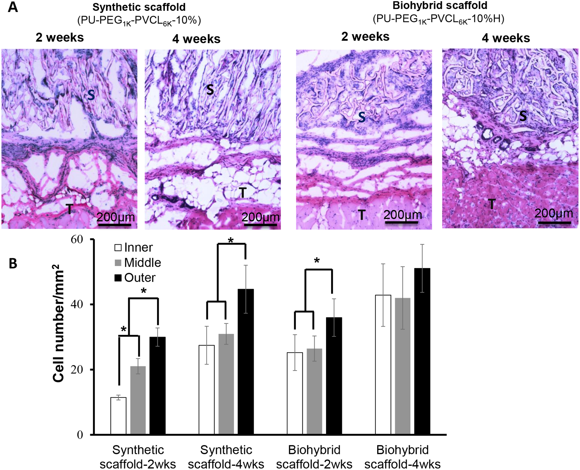
In vivo tissue compatibility of biohybrid scaffolds (PU-PEG1K-PVCL6K-10%H) in a rat subcutaneous model compared to the synthetic scaffold (PU-PEG1K-PVCL6K-10%) alone. (A) H&E staining of the implanted scaffolds and surrounding tissues after 2 and 4 weeks of implantation; (B) Cell number in inner, middle, and outer area on the implants was quantified for cell infiltration assessment. S: scaffold; T: Tissue. * represents significantly different groups (p < 0.05).
DISCUSSION
Bio-hybridization of the tissue-derived biomaterials and synthetic polymers is an efficient method to fabricate new biomaterials, which can benefit from the advantages of the tissue-derived (preservation of the native ECM composition and biological activity) and synthetic polymers (strong mechanical properties and durability).16, 59, 64 Currently, the biohybrid scaffolds have been primarily achieved by co-electrospinning a blend solution of synthetic polymers (e.g., polyurethanes and PCL) and tissue-derived biomaterials (e.g., dermal ECM, SIS, and UBM),65–68 and concurrently electrospinning polymer solution and electrospraying dermal ECM hydrogel.69 None of the above biohybrid scaffolds were specifically designed to be applied as biodegradable cardiac patches. Besides, those methods to fabricate the biohybrid scaffolds involved various organic solvents (e.g., hexafluoroisopropanol, dichloromethane, and dimethylformamide), which might adversely impact the bioactivity of the tissue-derived biomaterials.69 In our study, the biohybrid scaffolds were fabricated by injecting the cardiac ECM into the pores of the prepared PU-PEG-PVCL anisotropic scaffolds, and then solidified the hydrogel, which completely prevented the direct contact between the organic solvent and the cardiac ECM. Hence, this newly developed biohybrid cardiac patch not only structurally and mechanically mimic the native myocardium, but also possess high bioactivity originating from the blended cardiac ECM.
The desirable cardiac patch is better to mechanically match the native myocardium and have elasticity to synchronously contract and relax with native heart beating cycle. The cardiac patch stiffness also significantly impairs the phenotype maintenance of the cardiomyocytes, subsequently weakens their functional abilities (e.g., cell striation loss, beating frequency decreasing, and the reduced fraction of beating cells).39, 41 The increasing stiffness value is directly associated with the healing degree of the myocardial infarct tissue, which is significantly greater than the non-infarcted healthy myocardium.42 Hence, the cardiac patch should replace abnormal infarct tissue and in situ offer the stiffness with low initial modulus, which is comparable to that of the native healthy myocardium.21, 39 The native human myocardium possesses stiffness at the beginning of diastole at 0.01–0.02 MPa and at the end of diastole at 0.2–0.5 MPa. Hence, an idea cardiac patch should possess stiffness falling in the range of 0.02–0.5 MPa.21, 70 Most natural biomaterial based scaffolds, such as fibrin matrices (E=2.4–3.7 ×10⁻⁵ MPa),71 Matrigel (E=4.5×10⁻⁴ MPa),72 and alginate hydrogel (E=1.8×10⁻⁴ to 2.0×10⁻² MPa),73 have lower Young’s moduli than that of the human myocardium but with low mechanical strength. Some strong synthetic polymer based scaffolds, such as PLGA nanofibers (E=80 MPa),74 PCL nanofibers (E=8.84 MPa),75 poly(L-lactide-co-ε-caprolactone) nanofibers (PLCL; E=0.8–14.2 MPa)76 and poly(ester urethane)urea nanofibers (PEUU; E=3 MPa)68 are stiffer than the human myocardium. In our study, the initial moduli of the anisotropic PU-PEG-PVCL scaffolds were tuned by changing the chemical structure (block length of the soft segments) of the polyurethane backbone and polymer concentration. The initial moduli of the anisotropic PU-PEG1K-PVCL6K-5% scaffold (0.56 ± 0.11 MPa in longitudinal direction, and 0.51 ± 0.14 MPa in transversal direction in wet state) were comparable to that of the native heart tissue. Besides, the PU-PEG1K-PVCL6K-5% scaffold had suture retention strength at 27 ± 8 N/mm2 which is comparable to that of expanded poly(tetrafluoroethylene) (23 N/mm2) used clinically.77 Hence, the PU-PEG1K-PVCL6K based scaffold with soft segment block length (PVCL-PEG-PVCL, 3000-1000-3000) was promising for further mechanical optimization through scaffold geometry approach by altering TIPS parameters.
The PU-PEG1K-PVCL6K anisotropic scaffolds made from different polymer concentrations (5%, 8% and 10%) by TIPS were not only comparable with the native heart tissue on the stiffness, but also on ball-burst strength and biaxial mechanical properties which can reflect the scaffold behavior under physiologically-relevant loading conditions. Few literatures have compared both the stiffness of the synthetic cardiac patches and their biomechanics (e.g., suture retention, ball-burst strength and biaxial mechanical properties) with the native myocardium.44 The biodegradable cardiac patch is expected to possess sufficient ball-burst strength to prevent rupture or bleeding around the patch during the heart beating.78 The PU-PEG1K-PVCL6K-10% apparently had the ball burst strength at 20.7 ± 1.5 N (Figure 4), which was the closest to that of the native heart tissue (20.4 ± 6.0 N). In the biaxial testing (Figure 5), PU-PEG1K-PVCL6K-10% scaffold was stretched to a tension at 25 N/m as the native myocardium, while the PU-PEG1K-PVCL6K-5% scaffold was too weak to be stretched to the tension at 25 N/m (ruptured at 15 N/m). In addition, the PU-PEG1K-PVCL6K-10% scaffold had comparable anisotropy and stiffness to those of the native porcine myocardium and larger extensibilities in both CD and PD directions than the native myocardium. The structural anisotropy of the PU-PEG1K-PVCL6K-10% scaffold is the underlying mechanism of the anisotropic nonlinear biaxial behavior we observed and reported in Figure 5A. Hence, in terms of the results from ball burst test and biaxial testing, the PU-PEG1K-PVCL6K-10% scaffold showed more comparable biomechanical behaviors to the native myocardium than the PU-PEG1K-PVCL6K-5% and PU-PEG1K-PVCL6K-8% scaffolds.
After myocardial infarction occurs, ECM dysregulation has been shown to result in the progression of myocardial infarction, ventricular dilation and heart failure.79–80 No strategy has developed thus far to slow down such deteriorating processes. Here we propose that the introduction of ECM would create a regenerative environment for achieving favorable functional regeneration outcome. Specifically, biohybrid scaffold (PU-PEG1K-PVCL6K-10%H) was made by blending natural ECM with synthetic scaffold (PU-PEG1KPVCL6K-10%) to provide suitable cell signals to the patch. The biohybrid scaffolds consisting of synthetic scaffold and myocardium-derived ECM hydrogel had similar morphologies to a decellularized porcine myocardial scaffold.61 The heart derived extracellular matrix hydrogel have been used for clinical trial,81 and it showed improved cardiac function, ventricular volumes, global wall motion as well as cardiac muscle formation in pig MI models.82–83 Such combination did not significantly affect the mechanical properties of the synthetic scaffolds (Table 5), so, the biohybrid scaffolds maintained the optimized mechanical properties of the synthetic scaffolds. Furthermore, such physical combination can maximally maintain the high bioactivity of the myocardium-derived ECM. In fact, our results show that biohybid scaffold implants increase cell clusters formation and cell survival (Figure 7). The degradation of ECM could also provide ample space for cell infiltration and new cardiac tissue formation between the polymer fibers (Figure 7). It is rarely reported to combine the myocardium-derived ECM with synthetic porous scaffolds using this combination method to fabricate the biodegradable cardiac patch. Some studies reported the promotion on bioactivity of synthetic polymer scaffolds using tissue-derived biomaterials.65, 68–69, 84–85 The electrospun polyurethane/UBM hybrid scaffold showed greater amount of cellular infiltration than the synthetic polyurethane scaffold after 28 days of implantation in a rat subcutaneous model.65 The electrospun polyurethane/dermal ECM patch in a rat full-thickness abdominal wall replacement model for 8 weeks showed higher wall thickness and greater expression of associated smooth muscle actin–positive staining cells than that of the polyurethane patch.68 The polyurethane/dermal ECM scaffold fabricated by electrospinning and electrospraying implanted into a rat abdominal wall defect model exhibited more extensive cellular infiltration than the polyurethane scaffold.69 In another study, PCL was electrospun with decellularized porcine ECM nanoparticles derived from six different tissues (bone, cartilage, fat, liver, spleen and lung) to obtain biosynthetic scaffolds.85 These scaffolds containing bone, cartilage and fat ECM nanoparticles can promote osteogenesis compared to the pure PCL scaffold. Similarly, our biohybrid scaffold showed good tissue compatibility with mild immune response after 4 weeks of implantation while exhibited slightly higher cell penetration than the synthetic scaffold. The overall results support that, with unique cell penetration capability, biohybrid scaffold may be used to promote tissue regeneration and integration by facilitating the infiltration of surrounding host cells. In the future, further studies in heart infarction animal model will be performed to evaluate the effectiveness for heart function restoration.
CONCLUSION
A series of anisotropic polyurethane porous scaffolds were fabricated by TIPS technique. Their mechanical properties, including uniaxial mechanical properties, suture retention strengths, ball-burst strength and biaxial mechanical behaviors, were optimized to mechanically match the human myocardium through altering polymer types and concentrations. Furthermore, the optimized polyurethane scaffold was combined with the porcine myocardium-derived ECM to form the biohybrid scaffold. The biohybrid scaffold had similar morphologies to the acellular porcine myocardial scaffold and exhibited good tissue compatibility without affecting the optimal mechanical properties from the synthetic polyurethane scaffold. The bio-hybrid scaffold with optimized mechanical properties may find opportunities to be applied as a cell-free cardiac patch for CHF treatment.
Supplementary Material
ACKNOWLEDGMENTS
We greatly appreciate partial support from the Beginning Grant-in-Aid #14BGIA20510066 (Y.H.) from the American Heart Association, the Faculty Early Career Development (CAREER) award #1554835 (Y.H.) from the National Science Foundation, and R15HL140503 (Y.H.) from the National Institutes of Health in the USA.
Footnotes
Supporting Information
Stress-strain curves and cyclic stretch at 30 % deformation of PU-PVCL6K-5%, PU-PEG1KPVCL6K-5% and PU-PEG2K-PVCL6K-5% anisotropic porous scaffolds, and stress-strain curves of PU-PEG1K-PVCL6K-5%, 8%, and 10% anisotropic porous scaffolds in both longitudinal and transversal directions at dry and wet states.
The authors declare no competing financial interest.
REFERENCES
- (1).Benjamin EJ; Muntner P; Alonso A; Bittencourt MS; Callaway CW; Carson AP; Chamberlain AM; Chang AR; Cheng S; Das SR; et al. Heart disease and stroke statistics-2019 update: a report from the American Heart Association. Circulation 2019, 139,e56–e528, DOI: 10.1161/CIR.0000000000000659. [DOI] [PubMed] [Google Scholar]
- (2).Chatterjee P; Maddox KEJ US national trends in mortality from acute myocardial infarction and heart failure: policy success or failure? JAMA Cardiol. 2018, 3, 336–340. DOI: 10.1001/jamacardio.2018.0218. [DOI] [PMC free article] [PubMed] [Google Scholar]
- (3).Isomura T; Fukada Y; Miyazaki T; Yoshida M; Morisaki A; Endo M Posterior ventricular restoration treatment for heart failure: a review, past, present and future aspects. Gen Thorac Cardiovasc Surg. 2017, 65, 137–143, DOI: 10.1007/s11748-017-0750-8. [DOI] [PubMed] [Google Scholar]
- (4).Taylor DO; Edwards LB; Boucek MM; Trulock EP; Deng MC; Keck BM; Hertz MI Registry of the International Society for Heart and Lung Transplantation: twenty-second official adult heart transplant report--2005. T J Heart Lung Transplant. 2005, 24, 945–955, DOI: 10.1016/j.healun.2005.05.019. [DOI] [PubMed] [Google Scholar]
- (5).Ota T; Gilbert TW; Badylak SF; Schwartzman D; Zenati MA Electromechanical characterization of a tissue-engineered myocardial patch derived from extracellular matrix. J Thorac Cardiovasc Surg. 2007, 133, 979–985, DOI: 10.1016/j.jtcvs.2006.11.035. [DOI] [PubMed] [Google Scholar]
- (6).Lipinski MJ; Biondi-Zoccai GG; Abbate A; Khianey R; Sheiban I; Bartunek J; Vanderheyden M; Kim HS; Kang HJ; Strauer BE Impact of intracoronary cell therapy on left ventricular function in the setting of acute myocardial infarction: a collaborative systematic review and meta-analysis of controlled clinical trials. J Am Coll Cardiol 2007, 50, 1761–1767, DOI: 10.1016/j.jacc.2007.07.041. [DOI] [PubMed] [Google Scholar]
- (7).Laflamme MA; Chen KY; Naumova AV; Muskheli V; Fugate JA; Dupras SK; Reinecke H; Xu C; Hassanipour M; Police S; et al. Cardiomyocytes derived from human embryonic stem cells in pro-survival factors enhance function of infarcted rat hearts. Nat Biotechnol 2007, 25, 1015–1024, DOI: 10.1038/nbt1327. [DOI] [PubMed] [Google Scholar]
- (8).van Laake LW; Passier R; Doevendans PA; Mummery CL Human embryonic stem cell–derived cardiomyocytes and cardiac repair in rodents. Circ Res. 2008, 102, 1008–1010, DOI: 10.1161/CIRCRESAHA.108.175505. [DOI] [PubMed] [Google Scholar]
- (9).Zimmermann WH; Melnychenko I; Wasmeier G; Didié M; Naito H; Nixdorff U; Hess A; Budinsky L; Brune K; Michaelis B Engineered heart tissue grafts improve systolic and diastolic function in infarcted rat hearts. Nat Med. 2006, 12, 452–458, DOI: 10.1038/nm1394 [DOI] [PubMed] [Google Scholar]
- (10).Tulloch NL; Muskheli V; Razumova MV; Korte FS; Regnier M; Hauch KD; Pabon L; Reinecke H; Murry CE Growth of engineered human myocardium with mechanical loading and vascular coculture. Circ Res. 2011, 109, 47–59, DOI: 10.1161/CIRCRESAHA.110.237206. [DOI] [PMC free article] [PubMed] [Google Scholar]
- (11).Wang RM; Christman KL Decellularized myocardial matrix hydrogels: In basic research and preclinical studies. Adv Drug Deliv Rev. 2016, 96, 77–82, DOI: 10.1016/j.addr.2015.06.002. [DOI] [PMC free article] [PubMed] [Google Scholar]
- (12).Grover GN; Rao N; Christman KL Myocardial matrix–polyethylene glycol hybrid hydrogels for tissue engineering. Nanotechnology 2014, 25, 014011, DOI: 10.1088/0957-4484/25/1/014011. [DOI] [PMC free article] [PubMed] [Google Scholar]
- (13).Bejleri D; Davis ME Decellularized extracellular matrix materials for cardiac repair and regeneration. Adv Healthc Mater. 2019, 8, e1801217, DOI: 10.1002/adhm.201801217. [DOI] [PMC free article] [PubMed] [Google Scholar]
- (14).Wendel JS; Ye L; Zhang P; Tranquillo RT; Zhang JJ Functional consequences of a tissue-engineered myocardial patch for cardiac repair in a rat infarct model. Tissue Eng Part A. 2014, 20, 1325–1335, DOI: 10.1089/ten.TEA.2013.0312. [DOI] [PMC free article] [PubMed] [Google Scholar]
- (15).Wang H; Zhou J; Liu Z; Wang C Injectable cardiac tissue engineering for the treatment of myocardial infarction. J Cell Mol Med. 2010, 14, 1044–1055, DOI: 10.1111/j.1582-4934.2010.01046.x [DOI] [PMC free article] [PubMed] [Google Scholar]
- (16).Pok S; Jacot JG Biomaterials advances in patches for congenital heart defect repair. J Cardiovasc Transl Res. 2011, 4, 646–654, DOI: 10.1007/s12265-011-9289-8. [DOI] [PubMed] [Google Scholar]
- (17).Feric NT; Radisic M Strategies and challenges to myocardial replacement therapy. Stem Cells Transl Med. 2016, 5, 410–416, DOI: 10.5966/sctm.2015-0288. [DOI] [PMC free article] [PubMed] [Google Scholar]
- (18).Ozawa T; Mickle DA; Weisel RD; Koyama N; Ozawa S; Li RK Optimal biomaterial for creation of autologous cardiac grafts. Circulation 2002, 106, I-176–I-182, DOI: 10.1161/01.cir.0000032901.55215.cc. [DOI] [PubMed] [Google Scholar]
- (19).Jawad H; Ali N; Lyon A; Chen Q; Harding S; Boccaccini A Myocardial tissue engineering: a review. J Tissue Eng Regen Med. 2007, 1, 327–342, DOI: 10.1002/term.46. [DOI] [PubMed] [Google Scholar]
- (20).Rai R; Tallawi M; Barbani N; Frati C; Madeddu D; Cavalli S; Graiani G; Quaini F; Roether JA; Schubert DW Biomimetic poly (glycerol sebacate)(PGS) membranes for cardiac patch application. Mater Sci Eng C Mater Biol Appl. 2013, 33, 3677–3687, DOI: 10.1016/j.msec.2013.04.058. [DOI] [PubMed] [Google Scholar]
- (21).Chen QZ; Bismarck A; Hansen U; Junaid S; Tran MQ; Harding SE; Ali NN; Boccaccini AR Characterisation of a soft elastomer poly (glycerol sebacate) designed to match the mechanical properties of myocardial tissue. Biomaterials 2008, 29, 47–57, DOI: 10.1016/j.biomaterials.2007.09.010. [DOI] [PubMed] [Google Scholar]
- (22).Park H; Radisic M; Lim JO; Chang BH; Vunjak-Novakovic G A novel composite scaffold for cardiac tissue engineering. In Vitro Cell Dev Biol Anim. 2005, 41, 188–196, DOI: 10.1290/0411071.1. [DOI] [PubMed] [Google Scholar]
- (23).Chen Y; Wang J; Shen B; Chan CW; Wang C; Zhao Y; Chan HN; Tian Q; Chen Y; Yao C Engineering a freestanding biomimetic cardiac patch using biodegradable poly(lactic-co-glycolic acid)(PLGA) and human embryonic stem cell-derived ventricular cardiomyocytes (hESC-VCMs). Macromol Biosci. 2015, 15, 426–436, DOI: 10.1002/mabi.201400448. [DOI] [PubMed] [Google Scholar]
- (24).Piao H; Kwon JS; Piao S; Sohn JH; Lee YS; Bae JW; Hwang KK; Kim DW; Jeon O; Kim BS Effects of cardiac patches engineered with bone marrow-derived mononuclear cells and PGCL scaffolds in a rat myocardial infarction model. Biomaterials 2007, 28, 641–649, DOI: 10.1016/j.biomaterials.2006.09.009. [DOI] [PubMed] [Google Scholar]
- (25).Shin M; Ishii O; Sueda T; Vacanti J Contractile cardiac grafts using a novel nanofibrous mesh. Biomaterials 2004, 25, 3717–3723, DOI: 10.1016/j.biomaterials.2003.10.055. [DOI] [PubMed] [Google Scholar]
- (26).Ishii O; Shin M; Sueda T; Vacanti JP In vitro tissue engineering of a cardiac graft using a degradable scaffold with an extracellular matrix-like topography. J Thorac Cardiovasc Surg. 2005, 130, 1358–1363, DOI: 10.1016/j.jtcvs.2005.05.048. [DOI] [PubMed] [Google Scholar]
- (27).Mani MP; Jaganathan SK; Faudzi AAM; Sunar MS Engineered electrospun polyurethane composite patch combined with bi-functional components rendering high strength for cardiac tissue engineering. Polymers 2019, 11, E705, DOI: 10.3390/polym11040705. [DOI] [PMC free article] [PubMed] [Google Scholar]
- (28).Hashizume R; Hong Y; Takanari K; Fujimoto KL; Tobita K; Wagner WR The effect of polymer degradation time on functional outcomes of temporary elastic patch support in ischemic cardiomyopathy. Biomaterials 2013, 34, 7353–7363, DOI: 10.1016/j.biomaterials.2013.06.020. [DOI] [PMC free article] [PubMed] [Google Scholar]
- (29).Hashizume R; Fujimoto KL; Hong Y; Guan J; Toma C; Tobita K; Wagner WR Biodegradable elastic patch plasty ameliorates left ventricular adverse remodeling after ischemia–reperfusion injury: A preclinical study of a porous polyurethane material in a porcine model. J Thorac Cardiovasc Surg. 2013, 146, 391–399. e1, DOI: 10.1016/j.jtcvs.2012.11.013. [DOI] [PMC free article] [PubMed] [Google Scholar]
- (30).Srinivasan A; Sehgal PK Characterization of biocompatible collagen fibers--a promising candidate for cardiac patch. Tissue Eng Part C Methods. 2009, 16, 895–903, DOI: 10.1089/ten.TEC.2009.0475. [DOI] [PubMed] [Google Scholar]
- (31).Serpooshan V; Zhao M; Metzler SA; Wei K; Shah PB; Wang A; Mahmoudi M; Malkovskiy AV; Rajadas J; Butte MJ The effect of bioengineered acellular collagen patch on cardiac remodeling and ventricular function post myocardial infarction. Biomaterials 2013, 34, 9048–9055, DOI: 10.1016/j.biomaterials.2013.08.017. [DOI] [PMC free article] [PubMed] [Google Scholar]
- (32).Leor J; Aboulafia-Etzion S; Dar A; Shapiro L; Barbash I; Battler A; Granot Y; Cohen S Bioengineered cardiac grafts: a new approach to repair the infarcted myocardium? Circulation 2000, 102 III56–61, DOI: 10.1161/01.CIR.102.suppl_3.III-56. [DOI] [PubMed] [Google Scholar]
- (33).Leor J; Gerecht S; Cohen S; Miller L; Holbova R; Ziskind A; Shachar M; Feinberg MS; Guetta E; Itskovitz-Eldor J Human embryonic stem cell transplantation to repair the infarcted myocardium. Heart 2007, 93, 1278–1284, DOI: 10.1136/hrt.2006.093161. [DOI] [PMC free article] [PubMed] [Google Scholar]
- (34).Chrobak MOB; Hansen KJ; Gershlak JR; Vratsanos M; Kanellias M; Gaudette GR; Pins GD Design of a fibrin microthread-based composite layer for use in a cardiac patch. ACS Biomater. Sci. Eng 2017, 3, 1394–1403, DOI: 10.1021/acsbiomaterials.6b00547. [DOI] [PubMed] [Google Scholar]
- (35).Xiong Q; Ye L; Zhang P; Lepley M; Swingen C; Zhang L; Kaufman DS; Zhang J Bioenergetic and functional consequences of cellular therapy novelty and significance. Circ Res. 2012, 111, 455–468, DOI: 10.1161/CIRCRESAHA.112.269894. [DOI] [PMC free article] [PubMed] [Google Scholar]
- (36).Kofidis T; De Bruin JL; Hoyt G; Lebl DR; Tanaka M; Yamane T; Chang C-P; Robbins RC Injectable bioartificial myocardial tissue for large-scale intramural cell transfer and functional recovery of injured heart muscle. J Thorac Cardiovasc Surg. 2004, 128, 571–578, DOI: 10.1016/j.jtcvs.2004.05.021. [DOI] [PubMed] [Google Scholar]
- (37).Tan MY; Zhi W; Wei RQ; Huang YC; Zhou KP; Tan B; Deng L; Luo JC; Li XQ; Xie HQ Repair of infarcted myocardium using mesenchymal stem cell seeded small intestinal submucosa in rabbits. Biomaterials 2009, 30, 3234–3240, DOI: 10.1016/j.biomaterials.2009.02.013. [DOI] [PubMed] [Google Scholar]
- (38).Robinson KA; Li J; Mathison M; Redkar A; Cui J; Chronos NA; Matheny RG; Badylak SF Extracellular matrix scaffold for cardiac repair. Circulation 2005, 112, I135–I143, DOI: 10.1161/CIRCULATIONAHA.104.525436. [DOI] [PubMed] [Google Scholar]
- (39).Lakshmanan R; Krishnan UM; Sethuraman S Living cardiac patch: the elixir for cardiac regeneration. Expert Opin Biol Ther. 2012, 12, 1623–1640, DOI: 10.1517/14712598.2012.721770. [DOI] [PubMed] [Google Scholar]
- (40).Xu B; Li Y; Fang X; Thouas GA; Cook WD; Newgreen DF; Chen Q Mechanically tissue-like elastomeric polymers and their potential as a vehicle to deliver functional cardiomyocytes. J Mech Behav Biomed Mater. 2013, 28, 354–365, DOI: 10.1016/j.jmbbm.2013.06.005. [DOI] [PubMed] [Google Scholar]
- (41).Janmey PA; Miller RT Mechanisms of mechanical signaling in development and disease. J Cell Sci 2011, 124, 9–18, DOI: 10.1242/jcs.071001. [DOI] [PMC free article] [PubMed] [Google Scholar]
- (42).Connelly CM; McLaughlin RJ; Vogel WM; Apstein CS Reversible and irreversible elongation of ischemic, infarcted, and healed myocardium in response to increases in preload and afterload. Circulation 1991, 84, 387–399, DOI: 10.1161/01.CIR.84.1.387. [DOI] [PubMed] [Google Scholar]
- (43).Hashizume R; Hong Y; Takanari K; Fujimoto KL; Tobita K; Wagner WR The effect of polymer degradation time on functional outcomes of temporary elastic patch support in ischemic cardiomyopathy. Biomaterials 2013, 34, 7353–7363, DOI: 10.1016/j.biomaterials.2013.06.020. [DOI] [PMC free article] [PubMed] [Google Scholar]
- (44).D’Amore A; Yoshizumi T; Luketich SK; Wolf MT; Gu X; Cammarata M; Hoff R; Badylak SF; Wagner WR Bi-layered polyurethane-Extracellular matrix cardiac patch improves ischemic ventricular wall remodeling in a rat model. Biomaterials 2016, 107, 1–14, DOI: 10.1016/j.biomaterials.2016.07.039. [DOI] [PubMed] [Google Scholar]
- (45).Baheiraei N; Gharibi R; Yeganeh H; Miragoli M; Salvarani N; Di Pasquale E; Condorelli G Electroactive polyurethane/siloxane derived from castor oil as a versatile cardiac patch, part II: HL-1 cytocompatibility and electrical characterizations. J Biomed Mater Res A. 2016, 104, 1398–1407, DOI: 10.1002/jbm.a.35669. [DOI] [PubMed] [Google Scholar]
- (46).Xu C; Huang Y; Tang L; Hong Y Low-initial-modulus biodegradable polyurethane Elastomers for soft tissue regeneration. ACS Appl Mater Interfaces. 2017, 9, 2169–2180, DOI: 10.1021/acsami.6b15009. [DOI] [PMC free article] [PubMed] [Google Scholar]
- (47).Bian W; Jackman CP; Bursac N Controlling the structural and functional anisotropy of engineered cardiac tissues. Biofabrication 2014, 6, 024109 DOI: 10.1088/1758-5082/6/2/024109 [DOI] [PMC free article] [PubMed] [Google Scholar]
- (48).Saffitz JE; Kanter HL; Green KG; Tolley TK; Beyer EC Tissue-specific determinants of anisotropic conduction velocity in canine atrial and ventricular myocardium. Circ Res. 1994, 74, 1065–1070. DOI: 10.1161/01.res.74.6.1065. [DOI] [PubMed] [Google Scholar]
- (49).Wassenaar JW; Gaetani R; Garcia JJ; Braden RL; Luo CG; Huang D; DeMaria AN; Omens JH; Christman KL Evidence for mechanisms underlying the functional benefits of a myocardial matrix hydrogel for post-MI treatment. J Am Coll Cardiol. 2016, 67, 1074–1086, DOI: 10.1016/j.jacc.2015.12.035. [DOI] [PMC free article] [PubMed] [Google Scholar]
- (50).Ungerleider J; Johnson T; Rao N; Christman K Fabrication and characterization of injectable hydrogels derived from decellularized skeletal and cardiac muscle. Methods 2015, 84, 53–59, DOI: 10.1016/j.ymeth.2015.03.024. [DOI] [PMC free article] [PubMed] [Google Scholar]
- (51).Jeffords ME; Wu J; Shah M; Hong Y; Zhang G Tailoring material properties of cardiac matrix hydrogels to induce endothelial differentiation of human mesenchymal stem cells. ACS Appl Mater Interfaces. 2015, 7, 11053–11061, DOI: 10.1021/acsami.5b03195. [DOI] [PMC free article] [PubMed] [Google Scholar]
- (52).Guan J; Fujimoto KL; Sacks MS; Wagner WR Preparation and characterization of highly porous, biodegradable polyurethane scaffolds for soft tissue applications. Biomaterials 2005, 26, 3961–3971, DOI: 10.1016/j.biomaterials.2004.10.018. [DOI] [PMC free article] [PubMed] [Google Scholar]
- (53).Hsu YY; Gresser JD; Trantolo DJ; Lyons CM; Gangadharam PR; Wise DL Effect of polymer foam morphology and density on kinetics of in vitro controlled release of isoniazid from compressed foam matrices. J Biomed Mater Res. A 1997, 35, 107–116, DOI: . [DOI] [PubMed] [Google Scholar]
- (54).Chuang TW; Masters KS Regulation of polyurethane hemocompatibility and endothelialization by tethered hyaluronic acid oligosaccharides. Biomaterials 2009, 30, 5341–5351, DOI: 10.1016/j.biomaterials.2009.06.029. [DOI] [PubMed] [Google Scholar]
- (55).Xu C; Huang Y; Wu J; Tang L; Hong Y Triggerable degradation of polyurethanes for tissue engineering applications. ACS Appl Mater Interfaces. 2015, 7, 20377–20388, DOI: 10.1021/acsami.5b06242. [DOI] [PMC free article] [PubMed] [Google Scholar]
- (56).Freytes DO; Badylak SF; Webster TJ; Geddes LA; Rundell AE Biaxial strength of multilaminated extracellular matrix scaffolds. Biomaterials 2004, 25, 2353–2361, DOI: org/10.1016/j.biomaterials.2003.09.015. [DOI] [PubMed] [Google Scholar]
- (57).Feola A; Barone W; Moalli P; Abramowitch S Characterizing the ex vivo textile and structural properties of synthetic prolapse mesh products. Int Urogynecol J. 2013, 24, 559–564, DOI: 10.1007/s00192-012-1901-1. [DOI] [PMC free article] [PubMed] [Google Scholar]
- (58).Grashow JS; Yoganathan AP; Sacks MS Biaixal stress–stretch behavior of the mitral valve anterior leaflet at physiologic strain rates. Ann Biomed Eng. 2006, 34, 315–325, DOI: 10.1007/s10439-005-9027-y. [DOI] [PubMed] [Google Scholar]
- (59).Wang B; Borazjani A; Tahai M; Curry AL; Simionescu DT; Guan J; To F; Elder SH; Liao J Fabrication of cardiac patch with decellularized porcine myocardial scaffold and bone marrow mononuclear cells. J Biomed Mater Res A 2010, 94, 1100–1110, DOI: 10.1002/jbm.a.32781. [DOI] [PMC free article] [PubMed] [Google Scholar]
- (60).Wang B; Wang G; To F; Butler JR; Claude A; McLaughlin RM; Williams LN; de Jongh Curry AL; Liao J Myocardial scaffold-based cardiac tissue engineering: application of coordinated mechanical and electrical stimulations. Langmuir 2013, 29, 11109–11117, DOI: 10.1021/la401702w. [DOI] [PMC free article] [PubMed] [Google Scholar]
- (61).Wang B; Tedder ME; Perez CE; Wang G; de Jongh Curry AL; To F; Elder SH; Williams LN; Simionescu DT; Liao J Structural and biomechanical characterizations of porcine myocardial extracellular matrix. J Mater Sci Mater Med 2012, 23, 1835–1847, DOI: 10.1007/s10856-012-4660-0. [DOI] [PMC free article] [PubMed] [Google Scholar]
- (62).Singelyn JM; DeQuach JA; Seif-Naraghi SB; Littlefield RB; Schup-Magoffin PJ; Christman KL Naturally derived myocardial matrix as an injectable scaffold for cardiac tissue engineering. Biomaterials 2009, 30, 5409–5416, DOI: 10.1016/j.biomaterials.2009.06.045. [DOI] [PMC free article] [PubMed] [Google Scholar]
- (63).Li Y; Ma T; Kniss DA; Lasky LC; Yang ST Effects of filtration seeding on cell density, spatial distribution, and proliferation in nonwoven fibrous matrices. Biotechnol Prog. 2001, 17, 935–944, DOI: 10.1021/bp0100878. [DOI] [PubMed] [Google Scholar]
- (64).Lam MT; Wu JC Biomaterial applications in cardiovascular tissue repair and regeneration. Expert Rev Cardiovasc Ther. 2012, 10, 1039–1049, DOI: 10.1586/erc.12.99. [DOI] [PMC free article] [PubMed] [Google Scholar]
- (65).Stankus JJ; Freytes DO; Badylak SF; Wagner WR Hybrid nanofibrous scaffolds from electrospinning of a synthetic biodegradable elastomer and urinary bladder matrix. J Biomater Sci Polym Ed. 2008, 19, 635–652, DOI: 10.1163/156856208784089599. [DOI] [PMC free article] [PubMed] [Google Scholar]
- (66).Yoon H; Kim G Micro/nanofibrous scaffolds electrospun from PCL and small intestinal submucosa. J Biomater Sci Polym Ed. 2010, 21, 553–562, DOI: 10.1163/156856209X429166. [DOI] [PubMed] [Google Scholar]
- (67).Hong S; Kim G Electrospun micro/nanofibrous conduits composed of poly (epsilon-caprolactone) and small intestine submucosa powder for nerve tissue regeneration. J Biomed Mater Res B Appl Biomater. 2010, 94, 421–428, DOI: 10.1002/jbm.b.31670. [DOI] [PubMed] [Google Scholar]
- (68).Hong Y; Takanari K; Amoroso NJ; Hashizume R; Brennan-Pierce EP; Freund JM; Badylak SF; Wagner WR An elastomeric patch electrospun from a blended solution of dermal extracellular matrix and biodegradable polyurethane for rat abdominal wall repair. Tissue Eng Part C Methods. 2012, 18, 122–132, DOI: 10.1089/ten.TEC.2011.0295. [DOI] [PMC free article] [PubMed] [Google Scholar]
- (69).Hong Y; Huber A; Takanari K; Amoroso NJ; Hashizume R; Badylak SF; Wagner WR Mechanical properties and in vivo behavior of a biodegradable synthetic polymer microfiber-extracellular matrix hydrogel biohybrid scaffold. Biomaterials 2011, 32, 3387–3394, DOI: 10.1016/j.biomaterials.2011.01.025. [DOI] [PMC free article] [PubMed] [Google Scholar]
- (70).Venugopal JR; Prabhakaran MP; Mukherjee S; Ravichandran R; Dan K; Ramakrishna S Biomaterial strategies for alleviation of myocardial infarction. J R Soc Interface. 2012, 9, 1–19, DOI: 10.1098/rsif.2011.0301. [DOI] [PMC free article] [PubMed] [Google Scholar]
- (71).Urech L; Bittermann AG; Hubbell JA; Hall H Mechanical properties, proteolytic degradability and biological modifications affect angiogenic process extension into native and modified fibrin matrices in vitro. Biomaterials 2005, 26, 1369–1379, DOI: 10.1016/j.biomaterials.2004.04.045. [DOI] [PubMed] [Google Scholar]
- (72).Soofi SS; Last JA; Liliensiek SJ; Nealey PF; Murphy CJ The elastic modulus of Matrigel as determined by atomic force microscopy. J Struct Biol. 2009, 167, 216–219, DOI: 10.1016/j.jsb.2009.05.005. [DOI] [PMC free article] [PubMed] [Google Scholar]
- (73).Banerjee A; Arha M; Choudhary S; Ashton RS; Bhatia SR; Schaffer DV; Kane RS The influence of hydrogel modulus on the proliferation and differentiation of encapsulated neural stem cells. Biomaterials 2009, 30, 4695–4699, DOI: 10.1016/j.biomaterials.2009.05.050. [DOI] [PMC free article] [PubMed] [Google Scholar]
- (74).Prabhakaran MP; Kai D; Ghasemi-Mobarakeh L; Ramakrishna S Electrospun biocomposite nanofibrous patch for cardiac tissue engineering. Biomed Mater. 2011, 6, 055001, DOI: 10.1088/1748-6041/6/5/055001. [DOI] [PubMed] [Google Scholar]
- (75).Kai D; Prabhakaran MP; Jin G; Ramakrishna S Guided orientation of cardiomyocytes on electrospun aligned nanofibers for cardiac tissue engineering. J Biomed Mater Res B Appl Biomater. 2011, 98, 379–386, DOI: 10.1002/jbm.b.31862. [DOI] [PubMed] [Google Scholar]
- (76).Kwon IK; Kidoaki S; Matsuda T Electrospun nano-to microfiber fabrics made of biodegradable copolyesters: structural characteristics, mechanical properties and cell adhesion potential. Biomaterials 2005, 26, 3929–3939, DOI: 10.1016/j.biomaterials.2004.10.007. [DOI] [PubMed] [Google Scholar]
- (77).Anand S; Desai V; Alsmadi N; Kanneganti A; Nguyen DHT; Tran M; Patil L; Vasudevan S; Xu C; Hong Y Asymmetric sensory-motor regeneration of transected peripheral nerves using molecular guidance cues. Sci Rep. 2017, 7, 1–17. DOI: 10.1038/s41598-017-14331-x. [DOI] [PMC free article] [PubMed] [Google Scholar]
- (78).Roberts EG; Lee EL; Backman D; Buczek-Thomas JA; Emani S; Wong JY Engineering myocardial tissue patches with hierarchical structure-function. Ann Biomed Eng. 2015, 43, 762–773, DOI: 10.1007/s10439-014-1210-6. [DOI] [PMC free article] [PubMed] [Google Scholar]
- (79).KC P; Hong Y; Zhang G Cardiac tissue-derived extracellular matrix scaffolds for myocardial repair: advantages and challenges. Regen Biomater. 2019, 6, 185–199. DOI: 10.1093/rb/rbz017. [DOI] [PMC free article] [PubMed] [Google Scholar]
- (80).Graham H; Horn M; Trafford A Extracellular matrix profiles in the progression to heart failure: European Young Physiologists Symposium Keynote Lecture–Bratislava 2007. Acta Physiol (Oxf). 2008, 194, 3–21. DOI: 10.1111/j.1748-1716.2008.01881.x. [DOI] [PubMed] [Google Scholar]
- (81).Singelyn JM; Sundaramurthy P; Johnson TD; Schup-Magoffin PJ; Hu DP; Faulk DM; Wang J; Mayle KM; Bartels K; Salvatore M Catheter-deliverable hydrogel derived from decellularized ventricular extracellular matrix increases endogenous cardiomyocytes and preserves cardiac function post-myocardial infarction. J Am Coll Cardiol. 2012, 59, 751–763, DOI: 10.1016/j.jacc.2011.10.888. [DOI] [PMC free article] [PubMed] [Google Scholar]
- (82).Seif-Naraghi SB; Singelyn JM; Salvatore MA; Osborn KG; Wang JJ; Sampat U; Kwan OL; Strachan GM; Wong J; Schup-Magoffin PJ Safety and efficacy of an injectable extracellular matrix hydrogel for treating myocardial infarction. Sci Transl Med. 2013, 5, 173ra25, DOI: 10.1126/scitranslmed.3005503. [DOI] [PMC free article] [PubMed] [Google Scholar]
- (83).Hernandez MJ; Christman KL Designing acellular injectable biomaterial therapeutics for treating myocardial infarction and peripheral artery disease. JACC Basic Transl Sci. 2017, 2, 212–226, DOI: 10.1016/j.jacbts.2016.11.008. [DOI] [PMC free article] [PubMed] [Google Scholar]
- (84).Valentin JE; Turner NJ; Gilbert TW; Badylak SF Functional skeletal muscle formation with a biologic scaffold. Biomaterials 2010, 31, 7475–7484, DOI: 10.1016/j.biomaterials.2010.06.039. [DOI] [PMC free article] [PubMed] [Google Scholar]
- (85).Gibson M; Beachley V; Coburn J; Bandinelli PA; Mao HQ; Elisseeff J Tissue extracellular matrix nanoparticle presentation in electrospun nanofibers. Biomed Res Int. 2014, 2014, 469120, DOI: 10.1155/2014/469120. [DOI] [PMC free article] [PubMed] [Google Scholar]
Associated Data
This section collects any data citations, data availability statements, or supplementary materials included in this article.