

Summary
In this work, we introduce HI-Light, a surface-engineered glass-waveguide-based “shell-and-tube” type photothermal reactor which is both scalable in diameter and length. We examine the effect of temperature, light irradiation, and residence time on its photo-thermocatalytic performance for CO2 hydrogenation to form CO, with a cubic phase defect-laden indium oxide, In2O3-x(OH)y, catalyst. We demonstrate the light enhancement effect under a variety of reaction conditions. Notably, the light-on performance for the cubic nanocrystal photocatalyst exhibits a CO evolution rate at 15.40 mmol gcat−1 hr−1 at 300°C and atmospheric pressure. This is 20 times higher conversion rate per unit catalyst mass per unit time beyond previously reported In2O3-x(OH)y catalyst in the cubic form under comparable operation conditions and more than 5 times higher than that of its rhombohedral polymorph. This result underscores that improvement in photo-thermocatalytic reactor design enables uniform light distribution and better reactant/catalyst mixing, thus significantly improving catalyst utilization.
Subject Areas: Catalysis, Energy Sustainability, Energy Resources, Energy Storage
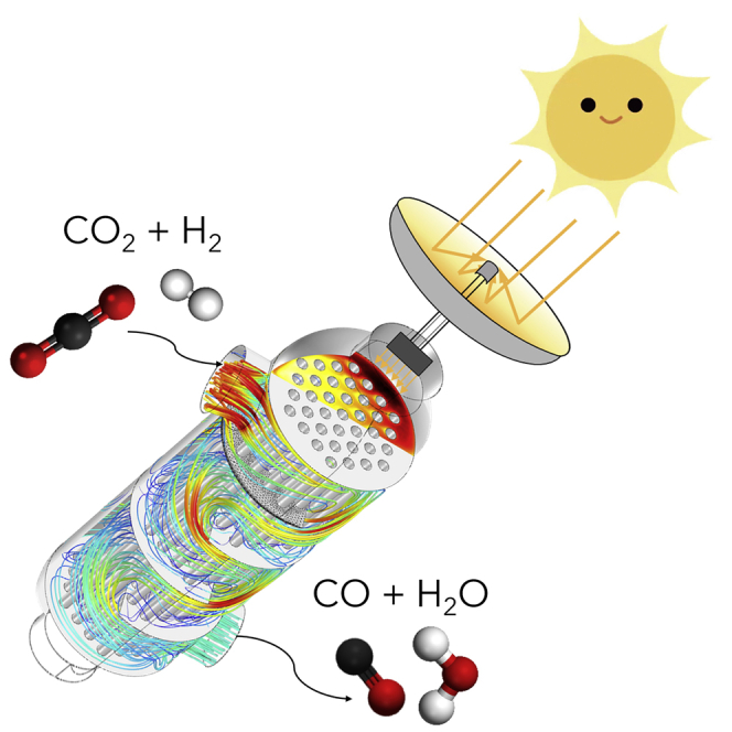
Graphical Abstract
Highlights
-
•
- A glass-waveguide-based “shell-and-tube” type photothermal reactor was developed
-
•
The reactor exhibited a high photothermal catalytic performance for CO2 reduction
-
•
- The modular reactor has potential for scale-up, both in diameter and length
-
•
The reactor design improves light distribution and reactant/catalyst mixing
Catalysis; Energy Sustainability; Energy Resources; Energy Storage
Introduction
Carbon dioxide (CO2) emission, as well as its associated climate change, is one of the most significant challenges facing humankind. Atmospheric CO2 concentrations continued their rising trend in 2019, peaking at 415 ppm in May (Kothandaraman and Heldebrant, 2020). Among the various CO2 mitigation technologies that have been studied (Boot-Handford et al., 2014; Mikkelsen et al., 2010; Gabardo et al., 2019; Wu and Ghoniem, 2018; Wang et al., 2020; Qi et al., 2011; Lu et al., 2018; Suter and Haussener, 2019; Tan et al., 2020), solar-driven approaches have emerged as most promising by virtue of the vast abundance of solar energy and inspiration from natural photosynthetic systems (Olah et al., 2011). The photochemical CO2 conversion into commodity chemicals and fuels offers the potential double benefit of generating economic benefits while simultaneously mitigating CO2 emission-related climate change. Despite this immense promise, efficient use of the Sun's energy through artificial photosynthesis remains challenging, and photocatalytic conversion of CO2 into solar fuels has a low yield and is not yet economically feasible at a larger scale.
To maximize the utilization of solar energy and achieve a higher conversion efficiency, researchers have explored the integration of thermo- and photo-catalytic approaches to create a process called photothermal catalysis. Although natural photosynthesis has been optimized through natural evolution over millions of years, photothermocatalytic CO2 reduction offers vast opportunities to reduce CO2 under conditions (i.e., elevated temperature and pressure) and with materials (e.g., emerging nanostructured inorganic catalysts) that nature has not had the opportunity to work with. Significant research efforts have focused on understanding and optimizing catalysts to enable photothermal CO2 reduction (Meng et al., 2014; O'Brien et al., 2014; Ghoussoub et al., 2019; Ozin, 2015), while reactor designs to allow the utilization and scale-up deployment of these catalysts have received less attention (Alaba et al., 2017). The reactor design has to be optimized at various length scales; at macroscopic scales, the design optimization involves a configuration that provides high surface area, low pressure drop, and high light intensity. At microscopic scales, i.e., thickness and porosity of the catalyst film coating the waveguide, there is a similar optimization. In the surface reaction limited regime, the photocatalytic conversion rate scales with light intensity. The thickness and porosity of the catalyst film coating the waveguide has to balance counteracting trends.
On the one hand, thick films ensure efficient light absorption; however, thin films with high porosity are required to ensure that the illuminated catalyst is exposed to the gas stream. In this manuscript, we focus on the first (i.e., macroscopic) design optimization. A high surface area of the heterogeneous catalyst should be exposed to the reactant gas flow stream while minimizing pressure drop through the reactor; moreover, light should be distributed uniformly and at relatively high intensity to the catalyst thin film. On the other hand, reactor geometry affects light distribution, and light absorption determines whether the photocatalyst can be activated. Consequently, there is a need for developing a photoreactor that ensures light availability and maximizes light scattering (Ali et al., 2019). On the other hand, factors affecting catalyst performance that have been studied in these simplified lab reactors might not be the same as that in large-scale reactors for the synthesis of chemicals/fuels at a much higher rate, according to a report by the National Academies Press (National Academies of Sciences, Engineering and Medicine, 2019). Finally, given the immense scale of the CO2 challenge, the scalability of the reactor design is a critical need to develop reactor design that can be readily scaled to levels required for industrial CO2 conversion.
A variety of photoreactor designs have been investigated to meet the challenges above, including slurry-type reactors, optofluidic membrane microreactors, fluidized bed reactors, fiber optic reactors, monolith reactors, and monolith fiber optic combined reactors (Nguyen and Wu, 2018; Cheng et al., 2017). Slurry-type reactors are easy to implement and are widely used. Still, these systems are usually constrained by the low light utilization efficiency, limited irradiated surface area, catalyst loss during recycling, difficulty in separating the catalyst from the reaction mixture, etc (Ola et al., 2012). For optofluidic membrane microreactors, the high surface-area-to-volume ratio, uniform light refraction, and enhanced photon and mass transfer can be achieved. Still, the low throughput for this design substantially limits its scale-up potential for practical applications (Cheng et al., 2016). Fluidized bed reactors could facilitate uniform particle mixing but usually require larger vessel size, thus higher capital cost. For optical fiber reactors, the benefits include the efficient catalyst processing capacity and a high surface area for reactions to take place, but the limitations include catalyst deactivation due to the rapid heat buildup of fibers, the complexity for light coupling, and a limited distance for light transmission under side illumination, which is governed by the exponential decay, thereby limiting the potential for scale-up application (Wu et al., 2008; Wu, 2010; Nguyen and Wu, 2008a, 2008b). For monolith reactors, the high surface-to-volume ratio can be achieved, and the system exhibits low pressure drops under high inflow rates. Still, the opacity of monolith channels will lead to low light utilization efficiency (Ola and Maroto-Valer, 2015; Tahir et al., 2015). Monolith fiber optic combined reactors utilize the optical fibers to provide internal illumination and have proved to increase system quantum efficiency. However, the utilization of the light is still not optimized. The system size is also constrained by the limited light transmission distance (Liou et al., 2011). Therefore, there still exists a research gap in designing scalable photoreactors, which can operate at elevated temperature and concurrently optimize light availability and maximize the catalyst/reactant interactions (Khan and Tahir, 2019).
In this work, we report a scalable glass-waveguide-based “shell-and-tube” photoreactor platform called “HI-Light,” which stands for “high (light) intensity.” We evaluated its photothermal catalytic performance for CO2 hydrogenation to form CO under various conditions. We validated the platform's efficiency with photothermocatalytic CO2 hydrogenation (i.e., reverse water-gas shift reaction, RWGS). We examined the effect of operating conditions, including temperature, light irradiation, and residence time on the CO2 reduction activity of this reactor platform.
Results and Discussion
HI-Light Reactor Platform
The assembly view of the HI-Light optofluidic photoreactor is presented in Figure 1. By integrating fluids and optics, optofluidic photoreactors offer enormous potentials for solar fuel production (Erickson et al., 2011). We adopted the baffle designs from traditional “shell-and-tube” heat exchangers to enhance the internal flow pattern, likely achieving better reactant mixing inside the reactor. We introduced an innovative variant to replace the internal tubes with light guiding glass waveguides coated with the catalyst. A detailed assembly view for inner components is included (see Video S1).
Figure 1.

Schematics for the Waveguide-based “Shell-and-Tube” Reactor
(A) Assembly view of the reactor.
(B) Waveguides coupled into baffles.
(C) Cross-sectional view of the reactor.
(D) Flow field comparison by the addition of baffles through computational fluid dynamics (CFD) simulations (overall flow rates: 40 mL min−1).
(E) Reverse water-gas shift (RWGS) reaction mechanism on the waveguide surface.
We constructed the photoreactor body, the end, and side flanges with 304 stainless steel (ss) (Accufab Inc). At each end, we applied two gaskets in between the flange and quartz window to ensure sealing and protect the quartz window from cracking. We introduced the light source from both ends of the reactor. The side flange design offered flexibility for introducing the inflow and outflow gases and measuring the pressure and temperature inside the reactor. Inside of the reactor body, we fixed glass waveguides by baffles with catalyst nanoparticles coated on the surface. All components in the reactor buildup can withstand harsh environments and have the potential for applications under high pressure and high temperature.
We engineered the surface roughness distribution of glass waveguides to improve light scattering (Cao et al., 2020a, Cao et al., 2020b). This was achieved through sandblasting the surfaces of the waveguides to increase the roughness in the middle (Technical Glass Products, SKU#3) and fire polishing both ends to improve light transmission and reduce surface roughness. This way, we created an arched distribution of surface roughness along the waveguides: smoother at both ends and rougher in the middle part. We applied a total of 6 baffles to fix 18 waveguides, with a diameter of 3 mm, a length of 230 mm, and an overall surface area of 390 cm2 (Figure 1B). Baffles were made from a 304 ss sheet (McMaster carr, 8983K114), and the ratio of the baffle height to the reactor's inner diameter was set as 90%. Figure 1C shows a cross-sectional view of the reactor: 18 holes of 3.2 mm were drilled on the baffles to fix the waveguides, and the middle hole of the baffle was threaded to fit a fully threaded corrosion-resistant rod (McMaster carr, 93250A005). The catalyst film was supported on the fused quartz light-guiding rod, with the gas flowing through open regions inside the reactor. Baffles not only settled the glass rods but also directed the flow pattern inside the reactor, resulting in better mixing of reactants. Figure 1D depicts the flow field comparison of the reactor with 6 baffles and the no-baffle scenario: with the addition of 6 baffles, the streamline mean distance has a 34% increase, whereas the pressure drop also increases by 3.2 times. We anticipated there to be an optimal number of baffles from a practical setting due to the compromise of improved reactant mixing and increased pressure drop. Figure 1E shows the mechanism of the photocatalytic RWGS reaction. Light is introduced into the glass rod waveguide, and the surface-supported catalyst absorbs the light energy. RWGS reaction occurs on the catalyst surface, where CO2 and H2 react and to form CO and H2O.
The reactor design with flange fittings offered ease to operate and the potential for scale-up. The reactor body's critical dimensions are all scalable: we can scale up the reactor diameter by utilizing vastly available tube parts and flange fittings; we can scale up the reactor length by increasing the light transmission distance via waveguide surface engineering. Figure 2A shows the current reactor's scale-up potential by comparing the original design, the diameter scaled-up design, and the one with length scale-up. The diameter scale-up can be readily achieved by expanding the tube diameter to contain more waveguides, coupled with a light source with a larger irradiation area. In the longer scaled-up version, the light attenuation along transmission can be alleviated by tuning the waveguide's surface properties, thus achieving a more uniform refraction profile and a greater transmission distance. Figure 2B illustrates the potential of operating multiple reactors in parallel, considering the throughput limitation for individual reactors.
Figure 2.

Scale-up Potential for the HI-Light Reactor Platform
(A) Scale-up of the reactor (original reactor, diameter scale-up, length scale-up).
(B) Reactors operating in parallel.
Figure 3A depicts the schematic for the CO2 reduction measurement setup. The side view (Figure 3B) and front view (Figure 3C) for the cross section of the reactor test setup were presented. The thermocouple tip was placed on the outer surface of the waveguide next to the outlet since this location exhibited the highest temperature compared with the other three ports. By controlling the temperature of this location to the desired value, we were underscoring our reactor performance since other parts were relatively cooler. An image of the experimental setup in operation is shown in Figure S1.
Figure 3.

Gas-Phase CO2 Photothermal Catalytic Reaction Test Platform for the HI-Light Reactor
(A) Schematic for the CO2 reduction measurement setup. Sizes not to scale. Heat insulation and inlet preheating components not shown for clarity.
(B) Cross section of the reactor test setup (side view). Waveguides are coated with In2O3-x(OH)y catalyst. The thermocouple tip touches the outer surface of the waveguide next to the outlet, where rod temperature is the highest.
(C) Cross section of the reactor test setup (front view).
We chose to use a cubic phase defect-laden indium oxide, In2O3-x(OH)y, as the photocatalyst in our study, due to its superior performance compared with that of other commonly used semiconductor photocatalysts, such as TiO2, one of the most well-studied photocatalysts for photo-driven CO2 reduction and water splitting (Liou et al., 2011; Liu et al., 2018). The cubic In2O3-x(OH)y nanoparticle exhibits excellent reactivity, selectivity, and stability, due to the presence of surface frustrated Lewis pairs (SFLPs) (Hoch et al., 2014; Ghuman et al., 2015, 2016; He et al., 2016). While excited, SFLPs can facilitate the photochemical CO2 reduction reaction by increasing the Lewis acidity and basicity. The morphology of the catalyst synthesized in the current study (Figure S2) by scanning electron microscopy and the Brunauer-Emmett-Teller specific surface area of the nanostructure were both in good agreement with the previous study (Wang et al., 2018).
Effect of Light Irradiation and Temperature
It has been found that high temperature (e.g., above 300°C) favors endothermic RWGS (CO2 + H2 ⇄ CO + H2O) over exothermic methanol production (CO2 + 3H2 ⇄ CH3OH + H2O) (Wang et al., 2018). To understand the effect of temperature on the photothermal RWGS activities, we tested the light on/off performances under three temperatures: 300°C, 325°C, and 350°C. We maintained the system at ambient pressure throughout the experiments, a constant feed ratio (H2:CO2 = 1), a constant overall inflow rate, thus a fixed mean residence time (40 mL min−1, 2.5 min). We used two identical UV light-emitting diodes (30 W, 380 nm) as light sources, lightening through both ends of the reactor at the intensity of 4.3 W cm−2. The effect of light irradiation and temperature on the CO2 reduction activity was presented (Figure 4). At 300°C, the CO evolution rate under dark and light operation conditions was 11.58 mmol gcat−1 h−1 and 15.40 mmol gcat−1 h−1, respectively. The corresponding CO2 conversion changed from 2.27% to 3% during the dark to light transition, and the thermodynamic equilibrium conversion was 13.6%. Such a light-powered CO evolution rate at 15.4 μmol gcat−1 hr−1 is a performance record. It is about 20 times higher than that of the best reported cubic form of In2O3-x(OH)y photocatalyst under comparable operation conditions and more than 5 times higher than that of the rhombohedral polymorph of In2O3-x(OH)y photocatalyst. On raising the temperature to 325°C, the CO evolution rate changed from 28.14 mmol gcat−1 h−1 (in dark) to 35.16 mmol gcat−1 h−1 (in light), and the CO2 conversion had a 25% increase, from 5.76% (in dark) to 7.2% (in light), getting closer to the equilibrium CO2 conversion at 15.75% at 325°C. When the reaction temperature was raised to 350°C, the CO evolution rates were 58.07 mmol gcat−1 h−1 and 42.43 mmol gcat−1 h−1, with and without light irradiation, respectively. The CO2 conversion also exhibited a light enhancement effect from 9.04% to 12.36%, further reaching the equilibrium CO2 conversion at 17.95% at 350°C. Both the relative CO2 conversion and absolute CO evolution rate had an evident increase under light irradiation under different temperatures tested above. We interpret the enhanced conversion and rate as an indication that photoexcitation reduces the reaction's activation energy relative to the dark (i.e., thermocatalytic) process. We anticipate that the light enhanced effect could be increased by tuning the waveguide surface properties to achieve more uniform light refraction inside the whole reactor.
Figure 4.

Effect of Light Radiation and Temperature on CO2 Reduction Activities
(A and B) CO evolution rate (A), and CO2 conversion (B) under different temperatures and light irradiation conditions. Error bars represent the standard deviation calculated from three measurements after the CO2 reduction activity becomes stable.
Effect of Residence Time
The mean residence time represents the average duration of a reactant within the reactor, which is defined as V/v, where V denotes the reactor volume and v stands for the overall flow rate (Fogler, 2016). To understand the effect of residence time on the reaction outcomes, we tested six flow rates: 5 mL min−1, 10 mL min−1, 20 mL min−1, 40 mL min−1, 60 mL min−1, and 80 mL min−1, the average residence time of which correlated to 20 min, 10 min, 5 min, 2.5 min, 1.67 min, and 1.25 min, respectively. The reactor was maintained at ambient pressure and 350°C under dark conditions. Both the relative CO2 conversion and absolute CO evolution rate were examined under different flow rates (Figure 5). At 5 mL min−1, the CO evolution rate and its corresponding CO2 conversion were 8.60 mmol gcat−1 h−1 and 14.66%, respectively. On raising the overall flow rate from 10 mL min−1 to 20 mL min−1, the CO evolution rate increased from 14.72 to 23.51 mmol gcat−1 h−1. The corresponding CO2 conversions for 10 mL min−1 and 20 mL min−1 were 12.55% and 10.02%, respectively. As the flow rate rose from 40 mL min−1 to 60 mL min−1, the CO evolution rate saw a further increase from 42.43 to 51.25 mmol gcat−1 h−1, while CO2 conversion showed a decrease from 9.04% to 7.28%. At 80 mL min−1, the CO evolution rate peaked at 64.63 mmol gcat−1 h−1 due to the excess amount of inflowing reactant, and CO2 conversion dropped to 6.89% since the residence time was at its lowest level.
Figure 5.

Effect of Residence Time on CO2 Reduction Activities
The change of CO evolution rate and CO2 conversion under different flow rates (350°C, in dark). The blue square denotes CO2 conversion, and the gray dot denotes the CO evolution rate.
Higher flow rates (i.e., shorter residence time) led to decreasing CO2 conversion (Figure 3). Conversely, lower flow rates (i.e., longer residence time) resulted in higher CO2 conversion. One can expect that by reducing the flow rate to zero (i.e., under stagnation conditions), the relative CO2 conversion can reach thermal equilibrium (17.95% at 350°C). On the other hand, if we keep increasing the flow rate, the absolute CO evolution rate will rise first, followed by reaching a maximum yield as constrained by the amount of catalyst. The flow rates tested above are still within the growing region. In this case, CO evolution increases with an increasing flow rate, which suggests that the reaction seems to be limited by gas transport to the catalyst surface.
Comparison with State-of-the-Art CO2 Reduction Activities
A detailed comparison of photo-thermocatalytic CO2 hydrogenation activities for the current study with state-of-art efficiencies for different reactors and catalyst materials is summarized (Table S1). Since methane, methanol, and ethanol were all in ppm levels, only carbon monoxide, the major product, was considered when comparing the product yields. In light of the elevated temperatures employed in our experiments, we sought to decouple the thermocatalytic and photocatalytic contributions to the CO2 reduction; to a first approximation, these contributions can be decoupled by considering the rate difference between dark and light conditions. In our “shell-and-tube” continuous flow reactor system, the cubic In2O3–x(OH)y nanocrystal photocatalyst exhibited an increased CO evolution rate from 11.58 mmol gcat−1 hr−1 (in dark) to 15.40 mmol gcat−1 hr−1 (in light) at 300°C and ambient pressure, leading to a light-induced CO evolution rate of 3.82 mmol gcat−1 hr−1. Under the same temperature and pressure conditions, CO evolution rates were observed by a previous study (Yan et al., 2019) to be ∼0.57 mmol gcat−1 hr−1 (in dark) and ∼0.73 mmol gcat−1 hr−1 (in light) for the same catalyst in the cubic form, with the light-induced CO rate at ∼0.16 mmol gcat−1 hr−1. All three rates were around 20 times lower than that in the current study, indicating that our reactor design enabled a more efficient catalyst utilization. They also tested the In2O3–x(OH)y nanocrystal photocatalyst in the rhombohedral form under the same temperature. They reported CO rates at ∼2.35 mmol gcat−1 hr−1 (in dark) and ∼2.36 mmol gcat−1 hr−1 (in light), with only 0.7% photo enhancement. These were the highest CO2 photocatalytic hydrogenation rates for the In2O3–x(OH)y nanocrystal photocatalyst-based systems so far and were still ∼4.9 times (in dark) and ∼6.5 times (in light) lower than that of the current study. This could be attributed to more uniform light coupling to a larger surface area of a catalyst film. We dispersed 50 mg catalyst to a total exposed surface area of 390 cm2 in our reactor platform, whereas the exposed surface was only 0.22 cm2 for 15 mg of catalyst in the literature. In addition to the uniform light distribution and catalyst availability described above, several other factors could have also contributed to our reactor's enhanced performance, such as the differences in system throughput and the enhanced reactant transport. A recent report (Wang et al., 2018) also examined the performance of cubic In2O3–x(OH)y nanocrystals under the same temperature. Still, the reported CO rates were around two orders of magnitude lower than that in the present study: 83 times for dark, 75 times for light, and 58 times for light-induced rates. The highest photothermal-driven CO evolution rate for the HI-Light reactor system was achieved at 350°C and atmospheric pressure, reaching 58.07 mmol gcat−1 hr−1, with the light-induced CO rate at 15.37 mmol gcat−1 hr−1. This sets a performance record for the In2O3–x(OH)y-based photothermal catalytic systems. In addition to the CO rate, we also evaluated our system's quantum efficiency, which also showed improvement over the state-of-the-art rate. The detailed discussion can be seen from the “Calculation of Quantum Efficiencies” in the Supplemental Information.
Conclusions
We demonstrate the application of a glass-waveguide-based “shell-and-tube” reactor, which we have called HI-Light. This modular reactor provides efficient light coupling for photocatalytic reactions at elevated temperatures. The reactor design is scalable, both in diameter and length. We examined the photothermal catalytic performance of the HI-Light platform for CO2 hydrogenation to form CO. We studied the effect of temperature, light irradiation, and residence time on the system efficiency for the HI-Light reactor with RWGS. We investigated the performance of cubic In2O3-x(OH)y nanocrystal as a photothermal catalyst. We reported 20 times improvement compared with the highest available CO evolution rates for the cubic form of In2O3-x(OH)y catalyst under comparable operation conditions in the literature and >5 times improvement compared with its rhombohedral polymorph. Under UV irradiation at 350°C and atmospheric pressure, the highest photothermal-driven CO evolution rate obtained was 58.07 mmol gcat−1 hr−1, with the light-induced CO rate at 15.37 mmol gcat−1 hr−1, setting a performance record for systems based on In2O3-x(OH)y photothermal catalysts. We have demonstrated reactor design as a useful approach to improve catalyst utilization, and we anticipate that the photocatalytic efficiency for the “shell-and-tube” HI-Light photoreactor system can be further increased through better reactor architecture (e.g., fluidized bed design) and waveguide engineering to maximize light, heat, and reactant coupling, thus improving catalyst utilization.
Limitations of the Study
We have shown the viability of applying the “shell-and-tube” concept in photoreactor design. However, there is still room for structure optimization (e.g., baffle and waveguide configurations, etc.) to maximize light utilization for the HI-Light reactor as described. A series of simulation studies on the effect of critical design and operating parameters on the flow field, light refraction behavior, and the heat and mass transfer performance for the reactor platform are needed. The simulation on the reactor will facilitate future reactor design to achieve a greater system efficiency.
Resource Availability
Lead Contact
Further information, requests, and inquiries should be directed to and will be fulfilled by the Lead Contact, David Erickson (de54@cornell.edu).
Materials Availability
This study did not generate new unique reagents.
Data and Code Availability
This study did not generate/analyze data sets/code.
Methods
All methods can be found in the accompanying Transparent Methods supplemental file.
Acknowledgments
D.E. and T.H. acknowledge primary funding support from the National Science Foundation STTR Award 1720824 & 1831166 and the Academic Adventure Award from the Atkinson Center for a Sustainable Future at Cornell. X.C., D.E., and T.H. appreciate the support from the Cornell Engineering Scale Up and Prototyping Award. X.C., T.H., and T.L. acknowledge the support from Engineering Learning Initiatives at Cornell Engineering through the Bill Nye ’77 Award. We would also like to acknowledge Dimensional Energy for allowing us to use their facilities to test our reactor's performance. This work was performed in part at the Cornell NanoScale Facility, an NNCI member supported by NSF Grant NNCI-2025233.
Authors Contribution
D.E., T.H., and X.C. conceived and designed the experiments. X.C., Y.K., and P.S. designed the reactor. X.C., Y.K., T.H., and T.L. carried out materials synthesis and catalytic testing. X.C. and T.H. performed data analysis. D.E. and T.H. supervised the project. X.C., D.E., and T.H. wrote the first draft. All authors contributed to the manuscript editing.
Declaration of Interests
T.H. and D.E. have an equity interest in Dimensional Energy – a company focused on commercializing the CO2 to fuel research presented herein.
Published: December 18, 2020
Footnotes
Supplemental Information can be found online at https://doi.org/10.1016/j.isci.2020.101856.
Contributor Information
Tobias Hanrath, Email: tobias.hanrath@cornell.edu.
David Erickson, Email: de54@cornell.edu.
Supplemental Information
References
- Alaba P.A., Abbas A., Daud W.M.W. Insight into catalytic reduction of CO2: catalysis and reactor design. J. Clean. Prod. 2017;140:1298–1312. [Google Scholar]
- Ali S., Flores M.C., Razzaq A., Sorcar S., Hiragond C.B., Kim H.R., Park Y.H., Hwang Y., Kim H.S., Kim H. Gas phase photocatalytic CO2 reduction,“A brief overview for benchmarking”. Catalysts. 2019;9:727. [Google Scholar]
- Boot-Handford M.E., Abanades J.C., Anthony E.J., Blunt M.J., Brandani S., Mac Dowell N., Fernández J.R., Ferrari M.-C., Gross R., Hallett J.P. Carbon capture and storage update. Energy Environ. Sci. 2014;7:130–189. [Google Scholar]
- Cao X., Hong T., Liu T., Akemi J., Hanrath T., Erickson D. Integrated Optics: Devices, Materials, and Technologies XXIV. Vol. 11283. International Society for Optics and Photonics; 2020. A scalable glass waveguide-based optofluidic photoreactor for converting CO2 to fuels; p. 112831N. [Google Scholar]
- Cao X., Hong T., Liu T., Erickson D. MOEMS and Miniaturized Systems XIX. Vol. 11293. International Society for Optics and Photonics; 2020. Engineering the glass waveguide surface for uniform light refraction inside an optofluidic photoreactor; p. 112930E. [Google Scholar]
- Cheng X., Chen R., Zhu X., Liao Q., An L., Ye D., He X., Li S., Li L. An optofluidic planar microreactor for photocatalytic reduction of CO2 in alkaline environment. Energy. 2017;120:276–282. [Google Scholar]
- Cheng X., Chen R., Zhu X., Liao Q., He X., Li S., Li L. Optofluidic membrane microreactor for photocatalytic reduction of CO2. Int. J. Hydrogen Energy. 2016;41:2457–2465. [Google Scholar]
- Erickson D., Sinton D., Psaltis D. Optofluidics for energy applications. Nat. Photon. 2011;5:583–590. [Google Scholar]
- Fogler H.S. Pearson Education; 2016. Elements of Chemical Reaction Engineering. [Google Scholar]
- Gabardo C.M., O’Brien C.P., Edwards J.P., McCallum C., Xu Y., Dinh C.-T., Li J., Sargent E.H., Sinton D. Continuous carbon dioxide electroreduction to concentrated multi-carbon products using a membrane electrode assembly. Joule. 2019;3:2777–2791. [Google Scholar]
- Ghoussoub M., Xia M., Duchesne P.N., Segal D., Ozin G. Principles of photothermal gas-phase heterogeneous CO2 catalysis. Energy Environ. Sci. 2019;12:1122–1142. [Google Scholar]
- Ghuman K.K., Hoch L.B., Wood T.E., Mims C., Singh C.V., Ozin G.A. Surface analogues of molecular frustrated Lewis pairs in heterogeneous CO2 hydrogenation catalysis. ACS Catal. 2016;6:5764–5770. [Google Scholar]
- Ghuman K.K., Wood T.E., Hoch L.B., Mims C.A., Ozin G.A., Singh C.V. Illuminating CO2 reduction on frustrated Lewis pair surfaces: investigating the role of surface hydroxides and oxygen vacancies on nanocrystalline In2O3-x(OH)y. Phys. Chem. Chem. Phys. 2015;17:14623–14635. doi: 10.1039/c5cp02613j. [DOI] [PubMed] [Google Scholar]
- He L., Wood T.E., Wu B., Dong Y., Hoch L.B., Reyes L.M., Wang D., Kübel C., Qian C., Jia J. Spatial separation of charge carriers in In2O3–x(OH)y nanocrystal superstructures for enhanced gas-phase photocatalytic activity. ACS nano. 2016;10:5578–5586. doi: 10.1021/acsnano.6b02346. [DOI] [PubMed] [Google Scholar]
- Hoch L.B., Wood T.E., O'Brien P.G., Liao K., Reyes L.M., Mims C.A., Ozin G.A. The rational design of a single-component photocatalyst for gas-phase CO2 reduction using both UV and visible light. Adv. Sci. 2014;1:1400013. doi: 10.1002/advs.201400013. [DOI] [PMC free article] [PubMed] [Google Scholar]
- Khan A.A., Tahir M. Recent advancements in engineering approach towards design of photo-reactors for selective photocatalytic CO2 reduction to renewable fuels. J. Co2 Util. 2019;29:205–239. [Google Scholar]
- Kothandaraman J., Heldebrant D.J. Towards environmentally benign capture and conversion: heterogeneous metal catalyzed CO2 hydrogenation in CO2 capture solvents. Green. Chem. 2020;22:828–834. [Google Scholar]
- Liou P.Y., Chen S.C., Wu J.C.S., Liu D., MacKintosh S., Maroto-Valer M., Linforth R. Photocatalytic CO2 reduction using an internally illuminated monolith photoreactor. Energy Environ. Sci. 2011;4:1487–1494. [Google Scholar]
- Liu X., Cao X.E., Liu Y., Li X., Wang M., Li M. Branched multiphase TiO2 with enhanced photoelectrochemical water splitting activity. Int. J. Hydrog. Energy. 2018;43:21365–21373. [Google Scholar]
- Lu M., Zhang J., Yao Y., Sun J., Wang Y., Lin H. Renewable energy storage via efficient reversible hydrogenation of piperidine captured CO2. Green. Chemistry. 2018;20:4292–4298. [Google Scholar]
- Meng X., Wang T., Liu L., Ouyang S., Li P., Hu H., Kako T., Iwai H., Tanaka A., Ye J. Photothermal conversion of CO2 into CH4 with H2 over Group VIII nanocatalysts: an alternative approach for solar fuel production. Angew. Chem. Int. Edition. 2014;53:11478–11482. doi: 10.1002/anie.201404953. [DOI] [PubMed] [Google Scholar]
- Mikkelsen M., Jørgensen M., Krebs F.C. The teraton challenge. A review of fixation and transformation of carbon dioxide. Energy Environ. Sci. 2010;3:43–81. [Google Scholar]
- National Academies of Sciences. Engineering and Medicine . The National Academies Press; 2019. Gaseous Carbon Waste Streams Utilization: Status and Research Needs. [Google Scholar]
- Nguyen T.V., Wu J.C.S. Photoreduction of CO2 in an optical-fiber photoreactor: effects of metals addition and catalyst carrier. Appl. Catal. A Gen. 2008;335:112–120. [Google Scholar]
- Nguyen T.V., Wu J.C.S. Photoreduction of CO2 to fuels under sunlight using optical-fiber reactor. Sol. Energ. Mat. Sol. C. 2008;92:864–872. [Google Scholar]
- Nguyen V.H., Wu J.C.S. Recent developments in the design of photoreactors for solar energy conversion from water splitting and CO2 reduction. Appl. Catal. A Gen. 2018;550:122–141. [Google Scholar]
- O'Brien P.G., Sandhel A., Wood T.E., Jelle A.A., Hoch L.B., Perovic D.D., Mims C.A., Ozin G.A. Photomethanation of gaseous CO2 over Ru/Silicon nanowire catalysts with visible and near-infrared photons. Adv. Sci. 2014;1:1400001. doi: 10.1002/advs.201400001. [DOI] [PMC free article] [PubMed] [Google Scholar]
- Ola O., Maroto-Valer M., Liu D., Mackintosh S., Lee C.W., Wu J.C.S. Performance comparison of CO2 conversion in slurry and monolith photoreactors using Pd and Rh-TiO2 catalyst under ultraviolet irradiation. Appl. Catal. B Environ. 2012;126:172–179. [Google Scholar]
- Ola O., Maroto-Valer M.M. Review of material design and reactor engineering on TiO2 photocatalysis for CO2 reduction. J. Photoch. Photobio. C. 2015;24:16–42. [Google Scholar]
- Olah G.A., Prakash G.S., Goeppert A. Anthropogenic chemical carbon cycle for a sustainable future. J. Am. Chem. Soc. 2011;133:12881–12898. doi: 10.1021/ja202642y. [DOI] [PubMed] [Google Scholar]
- Ozin G.A. Throwing new light on the reduction of CO2. Adv. Mater. 2015;27:1957–1963. doi: 10.1002/adma.201500116. [DOI] [PubMed] [Google Scholar]
- Qi G., Wang Y., Estevez L., Duan X., Anako N., Park A.H.A., Li W., Jones C.W., Giannelis E.P. High efficiency nanocomposite sorbents for CO2 capture based on amine-functionalized mesoporous capsules. Energy Environ. Sci. 2011;4:444–452. [Google Scholar]
- Suter S., Haussener S. Optimizing mesostructured silver catalysts for selective carbon dioxide conversion into fuels. Energy Environ. Sci. 2019;12:1668–1678. [Google Scholar]
- Tahir B., Tahir M., Amin N.S. Performance analysis of monolith photoreactor for CO2 reduction with H2. Energy Convers. Manag. 2015;90:272–281. [Google Scholar]
- Tan Y.C., Lee K.B., Song H., Oh J. Modulating local CO2 concentration as a general strategy for enhancing C−C coupling in CO2 electroreduction. Joule. 2020;4:1104–1120. [Google Scholar]
- Wang L., Ghoussoub M., Wang H., Shao Y., Sun W., Tountas A.A., Wood T.E., Li H., Loh J.Y.Y., Dong Y. Photocatalytic hydrogenation of carbon dioxide with high selectivity to methanol at atmospheric pressure. Joule. 2018;2:1369–1381. [Google Scholar]
- Wang X., Wang Z., de Arquer F.P.G., Dinh C.T., Ozden A., Li Y.C., Nam D.H., Li J., Liu Y.S., Wicks J. Efficient electrically powered CO2-to-ethanol via suppression of deoxygenation. Nat. Energy. 2020:1–9. [Google Scholar]
- Wu J.C.S. Renewable energy from the photocatalytic reduction of CO2 with H2O. In: ANPO M., KAMAT P.V., editors. Environmentally Benign Photocatalysts: Applications of Titanium Oxide-Based Materials. New York, NY. Springer; 2010. pp. 673–696. [Google Scholar]
- Wu J.C.S., Wu T.H., Chu T., Huang H., Tsai D. Application of optical-fiber photoreactor for CO2 photocatalytic reduction. Top. Catal. 2008;47:131–136. [Google Scholar]
- Wu X.Y., Ghoniem A.F. Hydrogen-assisted carbon dioxide thermochemical reduction on La0. 9Ca0. 1FeO3− δ membranes: a kinetics study. ChemSusChem. 2018;11:483–493. doi: 10.1002/cssc.201701372. [DOI] [PubMed] [Google Scholar]
- Yan T., Wang L., Liang Y., Makaremi M., Wood T.E., Dai Y., Huang B., Jelle A.A., Dong Y., Ozin G.A. Polymorph selection towards photocatalytic gaseous CO2 hydrogenation. Nat. Commun. 2019;10:2521. doi: 10.1038/s41467-019-10524-2. [DOI] [PMC free article] [PubMed] [Google Scholar]
Associated Data
This section collects any data citations, data availability statements, or supplementary materials included in this article.
Supplementary Materials
Data Availability Statement
This study did not generate/analyze data sets/code.