Chemical anticorrosion of metal electrode with benzotriazole inhibitor enhances the stability of perovskite solar cells.
Abstract
One big challenge for long-lived inverted perovskite solar cells (PSCs) is that commonly used metal electrodes react with perovskite layer, inducing electrode corrosion and device degradation. Motivated by the idea of metal anticorrosion, here, we propose a chemical anticorrosion strategy to fabricate stable inverted PSCs through introducing a typical organic corrosion inhibitor of benzotriazole (BTA) before Cu electrode deposition. BTA molecules chemically coordinate to the Cu electrode and form an insoluble and polymeric film of [BTA-Cu], suppressing the electrochemical corrosion and reaction between perovskite and the Cu electrode. PSCs with BTA/Cu show excellent air stability, retaining 92.8 ± 1.9% of initial efficiency after aging for 2500 hours. In addition, >90% of initial efficiency is retained after 85°C aging for over 1000 hours. PSCs with BTA/Cu also exhibit good operational stability, and 88.6 ± 2.6% of initial efficiency is retained after continuous maximum power point tracking for 1000 hours.
INTRODUCTION
Perovskite solar cells (PSCs) have reached over 25% efficiency because of their extraordinary optoelectronic properties (1, 2). Device stability becomes the next big challenge that remains to be addressed before the device’s commercialization (3). Stability issues of PSCs appear not only in perovskite layers but also in metal electrodes, especially for inverted PSCs (4–8). Lee and co-workers (9) have revealed that the corrosion of metal electrodes is a major origin of intrinsic device degradation through exploring the self-degradation process of PSCs. On the one hand, the decomposition products of perovskite (e.g., HI and I2) can react with commonly used metal electrodes (Al, Ag, and Cu) in inverted PSCs, which will further accelerate the decomposition of perovskite according to the law of chemical reaction equilibrium (10–13). For example, studies have demonstrated that Ag or Al electrodes will be corroded and form AgI or AlI3 at the electrode interface during device aging, thus leading to efficiency loss in PSCs (10, 11, 14, 15). On the other hand, a previous study has confirmed that ion migration in PSCs, which is another main reason for device degradation, is a reversible process and may not cause permanent device degradation under illumination since the efficiency can be fully recovered after being left in the dark for some time (14, 16). However, such a reversible process will be broken once the migrated ions (I−) react with metal electrodes (10, 14, 17). As a result, PSCs irreversibly degrade far ahead of the degradation of perovskite layers (12, 14). In addition, this is also one important reason why half of PSCs (without a transporting layer or metal electrode) usually show a much longer lifetime than full PSCs (18, 19). Although in real inverted PSCs, an electron transporting layer of PCBM ([6,6]-phenyl-C61 butyric acid methyl ester) commonly lies between a metal electrode and a perovskite layer, the iodine species in perovskite can diffuse through the PCBM layer and still react with the metal electrode, thus causing the electrode corrosion mentioned above (10, 14). To fabricate stable PSCs, physical separating methods are usually adopted through introducing extra diffusion barriers between perovskite and metal electrodes, such as carbon quantum dots (20), grapheme oxide (21, 22), graphitic carbon nitride (23), and cross-linked polymer (24). These barriers can effectively delay electrode corrosion and prolong device stability. However, the long-term stability issues of PSCs still exist as the iodine tends to diffuse through these barriers, especially under thermal or illumination conditions (13). Therefore, to further improve device stability, electrode corrosion caused by the chemical reaction between metal electrode and perovskite must be overcome.
Metal corrosion commonly appears not only in PSCs but also in electronic industries, communications, and marine equipment (25). For example, metal corrosion in Cl−-rich seawater will destroy the hull of ships (26). To avoid this corrosion, one of the most efficient approaches is chemical anticorrosion through using organic inhibitors (25). Among them, benzotriazole (BTA; Fig. 1A) is one of the most commonly used inhibitors, especially for Cu metal in halogen media (Cl−, for example) (25, 27, 28). Motivated by this anticorrosion idea, here, we introduce a BTA layer in inverted PSCs before Cu electrode deposition to avoid electrode corrosion and thus improve device stability (Fig. 1A; BTA is spin-coated on top of PCBM/C60/TPBi). Different from physical separating barriers, BTA molecules chemically coordinate with the Cu electrode and form an insoluble and polymeric film of [BTA-Cu] (Fig. 1A) (27), thus suppressing the electrochemical corrosion of the Cu electrode in halogen atmosphere and also blocking the reaction between perovskite and Cu electrode. In addition, recent studies indicate that metal electrode diffusion into a perovskite layer may be also a critical reason for device degradation (29, 30), while in PSCs with BTA, such a polymeric [BTA-Cu] film can also work as a diffusion barrier and block Cu diffusion toward the perovskite layer, thus further improving device stability. As a result, the device stability is greatly improved under both moisture air and thermal conditions. PSCs with BTA retain 92.8 ± 1.9% of the initial efficiency after aging 2500 hours in moisture air (relative humidity, 40 to 60%). In addition, over 90% of initial efficiency is still retained after aging 1100 hours at 85°C. The operational stability is also improved in PSCs with BTA, and 88.6 ± 2.6% of initial efficiency (91.0% recover from J-V curves) is retained after maximum power point (MPP) tracking for 1000 hours.
Fig. 1. Working mechanism of BTA anticorrosion.
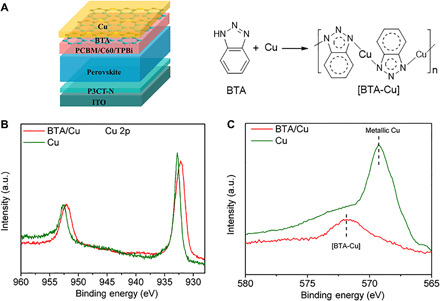
(A) Device configuration and schematic diagram of BTA anticorrosion. Note that a cross-linked perovskite layer is used here according to our previous work (24). (B) XPS of Cu 2p and (C) AES of Cu LLM in Cu film and Cu film deposited with BTA (BTA/Cu). Note that the Cu film is etched in AES characterization to avoid possible surface oxidation. a.u., arbitrary units.
RESULTS
Working mechanism
X-ray photoelectron spectroscopy (XPS) is conducted to investigate the working mechanism of BTA. Figure 1B shows the XPS of the Cu 2p orbit in Cu and BTA/Cu films (BTA deposited onto Cu surface). The Cu 2p1/2 and Cu 2p3/2 peaks in the bare Cu film appear at 952.6 and 932.8 eV, respectively, while in the BTA/Cu film, the Cu 2p1/2 (952.0 eV) and Cu 2p3/2 (932.2 eV) peaks shift toward low binding energy, indicating the coordination between BTA and Cu. The N 1s peak in BTA/Cu (399.9 eV) shows a 0.3-eV shift toward high binding energy in comparison with that in pure BTA (399.6 eV; fig. S1). Such a shift in N 1s peak indicates that the BTA coordinates with Cu through N atoms, forming a [BTA-Cu] polymeric film as shown in Fig. 1A, which agrees well with previous reports (31, 32). Auger electron spectroscopy (AES) of Cu LLM is also conducted to verify the formation of [BTA-Cu] (shown in Fig. 1C). In AES spectra, the peak around 569.2 eV is from metallic Cu, and the peak around 571.9 eV is from [BTA-Cu] (33). In BTA/Cu films, only the peak assigned to [BTA-Cu] is observed, and almost no signal from metallic Cu is observed, indicating that the Cu surface is completely covered by [BTA-Cu] in the BTA/Cu film.
Chemical anticorrosion
Cyclic voltammetry is used to investigate the electrochemical oxidation and reduction corrosion of Cu films (Fig. 2A). A pure Cu film is easy to be electrochemically corroded as obvious anodic and cathodic peaks are observed even in a neutral atmosphere of NaCl solutions (34, 35). However, in BTA/Cu films, Cu oxidation and reduction processes are completely suppressed in the presence of BTA (Fig. 2A, inset), indicating its excellent anticorrosion ability. Tafel polarization characterization is a typical method to evaluate metal corrosion. In Tafel curves, self-corrosion potential (Ecorr, where the corrosion current is smallest) represents the corrosion tendency, and corrosion current represents the corrosion rate (36). As shown in Fig. 2B, the major difference in Tafel polarization curves appears at the anodic section (right section), indicating that BTA molecules affect the anodic oxidation process of the Cu film. The BTA/Cu film shows an obvious Ecorr shift (−0.29 V) to positive potential in comparison with Cu film (−0.39 V), demonstrating that BTA/Cu film is much more difficult to be corroded. In addition, in Tafel curve of the Cu film, the corrosion current starts to rapidly increase at potential of 0.08 V and will be 380-fold higher than that in the BTA/Cu film, indicating the much faster corrosion rate in the Cu film. Note that the Cu color changes to dark brown (Fig. 2B, inset) after Tafel measurement, further confirming the easy corrosion of the Cu film. According to the results from cyclic voltammetry and Tafel polarization, it can be concluded that the Cu film is not only much easier but also much faster to be corroded than a BTA/Cu film.
Fig. 2. Electrochemical anticorrosion characterization of BTA.
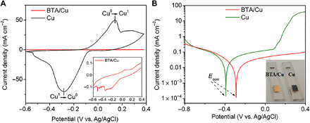
(A) Cyclic voltammetry and (B) Tafel polarization curves of pure Cu and BTA/Cu in NaCl solution (3.5 weight %). Note that BTA/Cu is formed by immersing the Cu film in BTA aqueous solution (1 mg ml−1) for 3 hours and then measured in NaCl solutions with BTA (0.1 mg ml−1). Ecorr represents self-corrosion potential. Inset: (A) Five hundred–fold enlarged curves of BTA/Cu. (B) Photographs of Cu and BTA/Cu after polarization test. Photo credit: Xiaodong Li, East China Normal University.
An immersing experiment is designed to directly observe the Cu corrosion in an I-rich atmosphere (Fig. 3A). FAPbI3 dispersion (50 mg ml−1 in isopropanol) is used to simulate the I-rich atmosphere in real PSCs, and the indium tin oxide (ITO)/Cu substrate is immersed in pure FAPbI3 dispersion or FAPbI3 dispersion containing BTA (1.0 mg ml−1). As shown in Fig. 3B, the color of the Cu film obviously changes to dark brown after 20 hours and then to gray completely after 50 hours when immersing in pure FAPbI3 dispersion, indicating the easy corrosion of Cu metal in this I-rich atmosphere; in FAPbI3 dispersion with BTA, no obvious change is observed in Cu color even after 50 hours. X-ray diffraction (XRD; Fig. 3C) shows that upon immersion in FAPbI3 dispersion, the peak from metallic Cu (43.5°) gradually weakens until it disappears completely after 50 hours. In addition, the peaks ascribed to CuI (25.4°) are gradually enhanced, indicating that Cu metal is easy to be corroded in FAPbI3 dispersion and converts into CuI eventually (19, 37). When immersing Cu film in the FAPbI3 dispersion containing BTA, BTA serves as a corrosion inhibitor and forms a compact polymeric [BTA-Cu] film on the Cu surface as shown in Fig. 1A. As a result, XRD peaks from metallic Cu are still obviously distinguished, and almost no CuI peaks appear in the Cu film even after immersing for 50 hours.
Fig. 3. Cu corrosion in I-rich atmosphere.
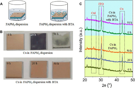
(A) Schematic diagram of immersing experiment. The ITO/Cu substrate is immersed in FAPbI3 dispersion (50 mg ml−1 in isopropanol) without or with a BTA inhibitor (1.0 mg ml−1). (B) Photographs and (C) XRD patterns of Cu films after immersion in FAPbI3 dispersion for different times. Photo credit: Xiaodong Li, East China Normal University.
In real PSCs with a Cu electrode, the electrode color will obviously change to dark brown after 85°C aging (Fig. 4A), indicating the existence of Cu corrosion. We design a device with a thin Cu electrode (10 nm; Fig. 4A) to simulate the situation around C60(TPBi)/Cu interface in real PSCs and use AES characterization to monitor the Cu variation during device aging. In control PSCs with Cu, an obvious AES signal assigned to Cu+ appears after 100 hours of aging and gradually increases, while the Cu0 signal gradually decreases until it disappears (Fig. 4A) (38), indicating that the chemical reaction and corrosion of the Cu electrode (from Cu0 to Cu+) indeed exist during PSC aging. When inserting BTA, Cu corrosion is suppressed, and strong Cu0 signal still appears even after aging for 500 hours (Fig. 4A). Cross-sectional scanning electron microscopy with energy-dispersive x-ray (SEM-EDX; Fig. 4B) and depth profiling of time-of-flight secondary ion mass spectrometry (ToF-SIMS; Fig. 4, C and D) are conducted to investigate element distribution in aged PSCs (85°C aging for 500 hours; specific details in Materials and Methods). The results show that iodine elements have diffused into the Cu electrode (Fig. 4B) and partially aggregate there in aged PSCs with Cu (marked in Fig. 4C), agreeing with the strong iodine signal in the Cu electrode (XPS in fig. S2). In addition, Cu diffusion toward perovskite is also clearly observed in PSCs with Cu. This Cu and I element diffusion may accelerate the reaction and corrosion of the Cu electrode, thus degrading device performance. In PSCs with BTA/Cu, BTA can chemically bond with Cu, thus inhibiting its diffusion. On the other hand, the interaction between BTA and Cu will form a polymeric film of [BTA-Cu], which may work as a diffusion barrier and block Cu or I diffusion. As a result, almost no iodine aggregation or Cu diffusion is observed in PSCs with BTA/Cu whether in cross-sectional SEM-EDX (Fig. 4B) or in depth profiling of ToF-SIMS (Fig. 4D).
Fig. 4. Cu electrode corrosion in PSCs under device aging.
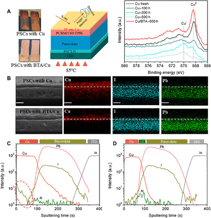
(A) Photographs of aged PSCs and AES variation of Cu LLM in PSCs. Note that in AES characterization, only a 10-nm Cu electrode was used to simulate the situation around the C60(TPBi)/Cu interface in real PSCs during 85°C aging in glove box. (B) Cross-sectional EDX mapping of Cu, I, and Pb elements in aged PSCs. Scale bars, 500 nm. (C and D) ToF-SIMS for depth profiling in aged PSCs with (C) Cu and (D) BTA/Cu after aging at 85°C for 500 hours in a glove box. Marked region indicates the I aggregation. Photo credit: Xiaodong Li, East China Normal University.
Long-term stability
On the basis of the anticorrosion strategy of BTA, we fabricate inverted PSCs with structure of ITO/P3CT-N (39)/(FAPbI3)0.95(MAPbBr3)0.05/PCBM/C60/TPBi/BTA/Cu. Since BTA is deposited using a spin-coating method, the BTA concentration (thickness) may affect the device performance. We firstly investigate the effect of BTA concentration on device performance and find that BTA of 1 mg ml−1 should be the best choice from the point of both device efficiency and stability (fig. S3 and tables S1 and S4). PSCs with BTA/Cu exhibit high efficiency (19.56%; fig. S5) with good air, thermal, and operational stability. As shown in Fig. 5A, PSCs with BTA/Cu retain 92.8 ± 1.9% of initial efficiency after 2500 hours of aging in moisture air without encapsulation (relative humidity, 40 to 60%; non-normalized data in fig. S6), while in control PSCs, only 68.8 ± 1.3% of initial efficiency is retained merely within 600 hours. Apart from air stability, thermal stability is also greatly improved, and 90.7 ± 2.5% of initial efficiency is retained in PSCs with BTA/Cu after aging at 85°C for 1100 hours (Fig. 5B and non-normalized data in fig. S7). In control PSCs, Cu electrode corrosion is non-negligible, and we have confirmed that the possible corrosion product of CuI will block electron transport in PSCs, greatly degrading device performance (fig. S8). In addition, photographs of aged PSCs show obvious shrinkage of active device area due to the edge corrosion of Cu electrode (fig. S9). To verify the effect of edge corrosion on device performance, we remeasure the aged PSCs using a mask (4 mm2) much smaller than initial device area (9 mm2) to avoid the already corroded section of the Cu electrode. The aged devices exhibit partially recovered efficiency (especially Jsc) when remeasuring with the mask in comparison with that without the mask (details in fig. S9). This result strongly indicates that the corrosion of Cu electrode indeed leads to device degradation. Because of this non-negligible Cu corrosion, PSCs with the Cu electrode exhibit poor thermal stability, retaining merely 49.5 ± 2.4% of initial efficiency after aging at 85°C for 1100 hours (specific photovoltaic parameter in fig. S10A and non-normalized data in fig. S7).
Fig. 5. Long-term stability.
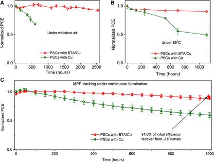
(A) Air stability of nonencapsulated PSCs aged in moisture air (relative humidity, 40 to 60%). (B) Thermal stability of nonencapsulated PSCs aged at 85°C in a glove box. (C) Long-term MPP tracking of PSCs under continuous illumination (white LED lamp). Note that the stability data are obtained from the average value among four separated PSCs. PCE, power conversion efficiency.
Apart from air and thermal stability, operational stability is of first concern for solar cells as it simulates the power generation process under real working conditions. In PSCs, ion migration is considered to be one major reason affecting its operational stability (40). Our previous work has demonstrated an in situ cross-linking method to suppress the ion migration along grain boundaries (24). However, even in this cross-linked perovskite layer, ions still start to migrate and dominate at 263 K (below room temperature), and the ions conductivity reaches as high as 0.608 × 10⁻⁹ S cm−1 at room temperature (298 K) (24). That is to say, ion migration still exists and cannot be ignored. As a result, ions in PSCs will migrate during MPP tracking and react with the metal electrode (Cu in this work), thus inducing electrode corrosion and device degradation. Just as shown in Fig. 5C, PSCs with Cu only retained 60.0 ± 4.2% of initial efficiency after MPP tracking under illumination for 1000 hours [white light-emitting diode (LED) lamp, light spectra shown in fig. S12 and specific photovoltaic parameter in fig. S10B]. However, in PSCs with BTA/Cu, the electrode corrosion and resulting device degradation can be avoided because of the anticorrosion property of BTA. Therefore, PSCs with BTA/Cu exhibit excellent operational stability, retaining 88.6 ± 2.6% (91.0% recover from J-V curves shown in fig. S11) of initial efficiency after MPP tracking for 1000 hours under continuous illumination (non-normalized original data shown in fig. S13).
Electrode corrosion–induced degradation
We design perovskite-based resistive random-access memory (RRAM) devices to study the ion migration–induced electrode reaction. Typical RRAM devices will exhibit two different states of high-resistance state (HRS) and low-resistance state (LRS) under external bias, which can be used to store information. At low bias, RRAM stays at HRS due to the resistance of perovskite itself. When increasing the bias to a certain value, the migrated I− ions in the perovskite layer start to react with the electrode and accumulate around, thus leaving many I− vacancies in the perovskite layer and forming a conductive filament for electric conduction (Fig. 6A) (41). As a result, the device current rapidly increases at this bias, transiting RRAM from HRS to LRS. The transiting bias from HRS to LRS represents the difficulty of ion migration and reaction with the top electrode. For example, a previous report has demonstrated that the RRAM with a Au top electrode exhibited much higher transiting bias than that with a Ag electrode, despite the same perovskite-based RRAM (41). In this work, we insert a PCBM layer between the perovskite layer and the top electrode to simulate the real conditions in PSCs (Fig. 6B), which is slightly different from typical RRAM. As shown in Fig. 6B, the RRAM devices with Cu exhibit much larger transiting bias (3.6 V) than that with Ag (1.1 V), agreeing well with the better stability of PSCs with Cu (12, 13). This result indicates that RRAM characterization is indeed a reasonable method to investigate the electrode corrosion and its effect on PSCs stability. In RRAM with BTA/Cu, the reaction with the top electrode is suppressed because of the existence of BTA (Fig. 6A). As a result, RRAM with BTA/Cu exhibit ~2.5 times higher transiting bias (8.9 V; Fig. 6B) than that with Cu (3.6 V). Note that the LRS will be retained once the RRAM transits from HRS to LRS (Fig. 6B), demonstrating the irreversible electrode reaction caused by ion migration. If in PSCs, then this irreversible electrode reaction will induce irreversible device degradation, which is the reason why electrode reaction or corrosion must be suppressed for stable PSCs. In devices with BTA/Cu, BTA molecules can effectively suppress the electrode reaction and corrosion, thus improving device stability.
Fig. 6. Ion migration–induced electrode corrosion.
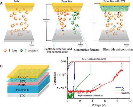
(A) Working mechanism of perovskite-based RRAM devices. (B) RRAM devices used in this work and the I-V curves in RRAM devices with different metal electrodes. The arrows indicate the scanning direction during measurement.
DISCUSSION
In conclusion, we demonstrate a chemical anticorrosion strategy to fabricate stable inverted PSCs through introducing a typical organic inhibitor of BTA. BTA chemically coordinates with a Cu electrode and form an insoluble and polymeric film of [BTA-Cu], thus enhancing the corrosion-resisting ability of the Cu electrode whether under air, thermal, or operating conditions. The resulting PSCs exhibit good operational stability, retaining 88.6 ± 2.6% of the initial efficiency after MPP tracking for 1000 hours under continuous illumination. In addition, the air and thermal stability are also greatly improved. The PSCs with BTA/Cu retain 92.8 ± 1.9% of initial efficiency after 2500 hours of aging in moisture air and 90.7 ± 2.5% of initial efficiency after 1100 hours of aging at 85°C. Our work highlights the role of electrode corrosion in device stability and proposes an effective method to fabricate stable inverted PSCs. Once the issue of electrode corrosion is overcome, the stability of inverted PSCs will be further improved when combining with the optimization of perovskite layer in future studies.
MATERIALS AND METHODS
Materials
PbBr2, PbI2, MACl, MABr, FAI, C60, and TPBi are obtained from Xi’an p-OLED (China). BTA and TMTA (trimethylolpropane triacrylate) additive are obtained from Aladdin (China). N,N′-dimethylformamide (DMF) and dimethyl sulfoxide (DMSO) are obtained from Alfa Aesar. Chlorobenzene (CB) solvent is obtained from Sigma-Aldrich.
Device fabrication
ITO substrates (20 mm by 20 mm) are cleaned sequentially in detergent, distilled water, acetone, and isopropanol. After drying with N2 flow, the substrates are transferred into chamber for O2 plasma. Then, P3CT-N (1 mg ml−1 in methanol) is spin-coated on these substrates at 4000 rpm and annealed at 100°C in air. Perovskite precursor solution is prepared by mixing 15 mg of MACl, 721.6 mg of FAPbI3, 28.7 mg of MAPbBr3 and 0.5 mg of TMTA additive in 1 ml of DMF/DMSO solvent (4:1, volume ratio). Perovskite layer is deposited by a typical antisolvent method in glove box. Perovskite precursor solution is spin-coated on ITO/P3CT-N at 2000 rpm for 10 s and 4000 rpm for 20 s. During spin coating, 300 μl of CB is dropped on the substrate 10 s before the end of the second program. The substrate is annealed at 140°C for 20 min and PCBM (10 mg ml−1) is spin-coated on top when cooling to room temperature. Forty-nanometer C60 and 8-nm TPBi are deposited through thermal evaporation. Then, BTA (1 mg ml−1in isopropanol) is further spin-coated on top at 4000 rpm. Last, 160-nm Cu is deposited to form the top electrode in a vacuum chamber (1 × 10⁻⁴ Pa). The device area is 9 mm2, defined by the overlap of Cu and ITO.
Characterization
The J-V characteristics are recorded using the Keithley 2400 SourceMeter under the solar simulator (Enlitech, SS-F5-3A) with simulated AM (Air Mass) 1.5G illumination (100 mW cm−2). The light source is a 450-W xenon lamp calibrated by a standard Si reference solar cell (Enli/SRC2020, SRC-00201). Unless otherwise stated, The J-V curves are all measured in a glove box at room temperature under a forward scan (unless otherwise stated) from 1.2 to −0.2 V with a dwell time of 50 ms (the delay between measurement points is 50 ms). The EQE (external quantum efficiency) measurement is conducted in air using a Newport quantum efficiency measurement system (ORIEL IQE 200TM) combined with a lock-in amplifier and a 150-W xenon lamp. The light intensity at each wavelength is calibrated by one standard Si/Ge solar cell.
Cyclic voltammetry and Tafel polarization curves are recorded by an electrochemical workstation (CHI660D) with a three-electrode system. SEM-EDX is recorded by SEM (FEI Quanta FEG 250) with an accelerating voltage of 20 kV. ToF-SIMS is conducted on TOF-SIMS 5 (iontof) with a sputter energy of 1 keV. The sample preparation is similar to PSC fabrication except that the Cu electrode is deposited without any mask. After evaporating the Cu electrode, the sample is heated on hot plate at 85°C in a glove box for 500 hours and then transferred for characterization.
RRAM measurement: A perovskite layer and a BTA layer are deposited similar to PSCs. The PCBM layer is spin-coated on top of the perovskite with a low density of 3 mg ml −1. Ag or Cu (100 nm) is deposited to form the top electrode with a diameter of 100 μm. RRAM devices are measured at room temperature using a semiconductor characterization system (Keithley 4200-SCS).
Stability measurement
Air stability is recorded by storing the nonencapsulated devices in air (relative humidity, 40 to 60%). Before J-V measurement, the PSCs are put into a vacuum chamber for 10 to 20 min to remove the moisture absorbed on surface.
Thermal stability is recorded by storing the nonencapsulated devices on a hot plate setting at 85°C in a glove box [H2O < 0.1 parts per million (ppm) and O2 < 0.1 ppm]. The J-V curves are measured after cooling the PSCs down to room temperature.
Operational stability: Operational stability is recorded with a 16-channel MPP measuring system under continuous illumination (white LED) at room temperature. During the MPP tracking, the light intensity can be automatically calibrated with a Si reference diode. To calibrate the initial illumination intensity to 100 mW cm−2, the PSC is first measured under the solar simulator (Enlitech, SS-F5-3A) with simulated AM 1.5G illumination to obtained a Jsc. Then, the PSC is measured again under the white LED lamp to reach the same Jsc through regulate the intensity of the LED lamp.
Supplementary Material
Acknowledgments
Funding: This work was supported by National Natural Science Foundation of China (51903242, 61974150, and 51773213), Natural Science Foundation of Zhejiang Province of China (LQ19E030008), Key Research Program of Frontier Sciences, CAS (QYZDB-SSW-JSC047). The Fundamental Research Funds for the Central Universities, and the National Youth Top-notch Talent Support Program. Author contributions: J.F. supervised the whole project. J.F. and X.L. conceived the idea. X.L. designed the experiments, fabricated all the devices, and conducted the characterization. S.F. and W.Z. participated in the stability measurements. S.K. and W.S. helped conduct the cyclic voltammetry and Tafel polarization curves. X.L. and J.F. discussed and co-wrote the paper. Competing interests: The authors declare that they have no competing interests. Data and materials availability: All data needed to evaluate the conclusions in the paper are present in the paper and/or the Supplementary Materials. Additional data related to this paper may be requested from the authors.
SUPPLEMENTARY MATERIALS
Supplementary material for this article is available at http://advances.sciencemag.org/cgi/content/full/6/51/eabd1580/DC1
REFERENCES AND NOTES
- 1.NREL, Best research efficiencies; https://www.nrel.gov/pv/assets/pdfs/best-research-cell-efficiencies.20200925.pdf.
- 2.Jiang Q., Zhao Y., Zhang X., Yang X., Chen Y., Chu Z., Ye Q., Li X., Yin Z., You J., Surface passivation of perovskite film for efficient solar cells. Nat. Photonics 13, 460–466 (2019). [Google Scholar]
- 3.Rong Y., Hu Y., Mei A., Tan H., Saidaminov M. I., Seok S. I., McGehee M. D., Sargent E. H., Han H., Challenges for commercializing perovskite solar cells. Science 361, eaat8235 (2018). [DOI] [PubMed] [Google Scholar]
- 4.Kim H. S., Seo J. Y., Park N. G., Material and device stability in perovskite solar cells. ChemSusChem 9, 2528–2540 (2016). [DOI] [PubMed] [Google Scholar]
- 5.Leijtens T., Bush K., Cheacharoen R., Beal R., Bowring A., McGehee M. D., Towards enabling stable lead halide perovskite solar cells; interplay between structural, environmental, and thermal stability. J. Mater. Chem. A 5, 11483–11500 (2017). [Google Scholar]
- 6.Rivkin B., Fassl P., Sun Q., Taylor A. D., Chen Z., Vaynzof Y., Effect of ion migration-induced electrode degradation on the operational stability of perovskite solar cells. ACS Omega 3, 10042–10047 (2018). [DOI] [PMC free article] [PubMed] [Google Scholar]
- 7.Lee H., Lee C., Analysis of ion-diffusion-induced interface degradation in inverted perovskite solar cells via restoration of the Ag electrode. Adv. Energy Mater. 8, 1702197 (2018). [Google Scholar]
- 8.Sanehira E. M., Tremolet de Villers B. J., Schulz P., Reese M. O., Ferrere S., Zhu K., Lin L. Y., Berry J. J., Luther J. M., Influence of electrode interfaces on the stability of perovskite solar cells: Reduced degradation using MoOx/Al for hole collection. ACS Energy Lett. 1, 38–45 (2016). [Google Scholar]
- 9.Back H., Kim G., Kim J., Kong J., Kim T. K., Kang H., Kim H., Lee J., Lee S., Lee K., Achieving long-term stable perovskite solar cells via ion neutralization. Energ. Environ. Sci. 9, 1258–1263 (2016). [Google Scholar]
- 10.Li J., Dong Q., Li N., Wang L., Direct evidence of ion diffusion for the silver-electrode-induced thermal degradation of inverted perovskite solar cells. Adv. Energy Mater. 7, 1602922 (2017). [Google Scholar]
- 11.Kato Y., Ono L. K., Lee M. V., Wang S., Raga S. R., Qi Y., Silver iodide formation in methyl ammonium lead iodide perovskite solar cells with silver top electrodes. Adv. Mater. Interfaces 2, 1500195 (2015). [Google Scholar]
- 12.Deng Y., Dong Q., Bi C., Yuan Y., Huang J., Air-stable, efficient mixed-cation perovskite solar cells with Cu electrode by scalable fabrication of active layer. Adv. Energy Mater. 6, 1600372 (2016). [Google Scholar]
- 13.Zhao J., Zheng X., Deng Y., Li T., Shao Y., Gruverman A., Shield J., Huang J., Is Cu a stable electrode material in hybrid perovskite solar cells for a 30-year lifetime? Energ. Environ. Sci. 9, 3650–3656 (2016). [Google Scholar]
- 14.Guerrero A., You J., Aranda C., Kang Y. S., Garcia-Belmonte G., Zhou H., Bisquert J., Yang Y., Interfacial degradation of planar lead halide perovskite solar cells. ACS Nano 10, 218–224 (2016). [DOI] [PubMed] [Google Scholar]
- 15.Han Y., Meyer S., Dkhissi Y., Weber K., Pringle J. M., Bach U., Spiccia L., Cheng Y.-B., Degradation observations of encapsulated planar CH3NH3PbI3 perovskite solar cells at high temperatures and humidity. J. Mater. Chem. A 3, 8139–8147 (2015). [Google Scholar]
- 16.Domanski K., Roose B., Matsui T., Saliba M., Turren-Cruz S.-H., Correa-Baena J.-P., Carmona C. R., Richardson G., Foster J. M., De Angelis F., Ball J. M., Petrozza A., Mine N., Nazeeruddin M. K., Tress W., Grätzel M., Steiner U., Hagfeldt A., Abate A., Migration of cations induces reversible performance losses over day/night cycling in perovskite solar cells. Energ. Environ. Sci. 10, 604–613 (2017). [Google Scholar]
- 17.Besleaga C., Abramiuc L. E., Stancu V., Tomulescu A. G., Sima M., Trinca L., Plugaru N., Pintilie L., Nemnes G. A., Iliescu M., Svavarsson H. G., Manolescu A., Pintilie I., Iodine migration and degradation of perovskite solar cells enhanced by metallic electrodes. J. Phys. Chem. Lett. 7, 5168–5175 (2016). [DOI] [PubMed] [Google Scholar]
- 18.Wang L., Zhou H., Hu J., Huang B., Sun M., Dong B., Zheng G., Huang Y., Chen Y., Li L., Xu Z., Li N., Liu Z., Chen Q., Sun L.-D., Yan C.-H., A Eu3+-Eu2+ ion redox shuttle imparts operational durability to Pb-I perovskite solar cells. Science 363, 265–270 (2019). [DOI] [PubMed] [Google Scholar]
- 19.Li X., Fu S., Liu S., Wu Y., Zhang W., Song W., Fang J., Suppressing the ions-induced degradation for operationally stable perovskite solar cells. Nano Energy 64, 103962 (2019). [Google Scholar]
- 20.Bi E., Chen H., Xie F., Wu Y., Chen W., Su Y., Islam A., Grätzel M., Yang X., Han L., Diffusion engineering of ions and charge carriers for stable efficient perovskite solar cells. Nat. Commun. 8, 15330 (2017). [DOI] [PMC free article] [PubMed] [Google Scholar]
- 21.Arora N., Dar M. I., Hinderhofer A., Pellet N., Schreiber F., Zakeeruddin S. M., Grätzel M., Perovskite solar cells with CuSCN hole extraction layers yield stabilized efficiencies greater than 20%. Science 358, 768–771 (2017). [DOI] [PubMed] [Google Scholar]
- 22.Wang Y., Wu T., Barbaud J., Kong W., Cui D., Chen H., Yang X., Han L., Stabilizing heterostructures of soft perovskite semiconductors. Science 365, 687–691 (2019). [DOI] [PubMed] [Google Scholar]
- 23.Bi E., Tang W., Chen H., Wang Y., Barbaud J., Wu T., Kong W., Tu P., Zhu H., Zeng X., He J., Kan S.-i., Yang X., Grätzel M., Han L., Efficient perovskite solar cell modules with high stability enabled by iodide diffusion barriers. Joule 3, 2748–2760 (2019). [Google Scholar]
- 24.Li X., Zhang W., Wang Y.-C., Zhang W., Wang H.-Q., Fang J., In-situ cross-linking strategy for efficient and operationally stable methylammoniun lead iodide solar cells. Nat. Commun. 9, 3806 (2018). [DOI] [PMC free article] [PubMed] [Google Scholar]
- 25.Antonijevic M. M., Petrovic M. B., Copper corrosion inhibitors. A review. Int. J. Electrochem. Sci. 3, 1–28 (2008). [Google Scholar]
- 26.Gerengi H., Darowicki K., Bereket G., Slepski P., Evaluation of corrosion inhibition of brass-118 in artificial seawater by benzotriazole using dynamic EIS. Corros. Sci. 51, 2573–2579 (2009). [Google Scholar]
- 27.Cotton J. B., Scholes I. R., Benzotriazole and related compounds as corrosion inhibitors for copper. Br. Corros. J. 2, 1–5 (1967). [Google Scholar]
- 28.Caprioli F., Decker F., Castro V. D., Durable Cu corrosion inhibition in acidic solution by SAMs of benzenethiol. J. Electroanal. Chem. 657, 192–195 (2011). [Google Scholar]
- 29.Domanski K., Correa-Baena J.-P., Mine N., Nazeeruddin M. K., Abate A., Saliba M., Tress W., Hagfeldt A., Grätzel M., Not all that glitters is gold: Metal-migration-induced degradation in perovskite solar cells. ACS Nano 10, 6306–6314 (2016). [DOI] [PubMed] [Google Scholar]
- 30.Guarnera S., Abate A., Zhang W., Foster J. M., Richardson G., Petrozza A., Snaith H. J., Improving the long-term stability of perovskite solar cells with a porous Al2O3 buffer layer. J. Phys. Chem. Lett. 6, 432–437 (2015). [DOI] [PubMed] [Google Scholar]
- 31.Subramanian R., Lakshminarayanan V., Effect of adsorption of some azoles on copper passivation in alkaline medium. Corros. Sci. 44, 535–554 (2002). [Google Scholar]
- 32.Rubim J., Gutz I. G. R., Sala O., Orville-Thomas W. J., Surface enhanced Raman spectra of benzotriazole adsorbed on a copper electrode. J. Mol. Struct. 100, 571–583 (1983). [Google Scholar]
- 33.Cohen S., Brusic V., Kaufman F., Frankel G., Motakef S., Rush B., X-ray photoelectron spectroscopy and ellipsometry studies of the electrochemically controlled adsorption of benzotriazole on copper surfaces. J. Vac. Sci. Technol. A 8, 2417–2424 (1990). [Google Scholar]
- 34.Whelan C. M., Kinsella M., Carbonell L., Meng Ho H., Maex K., Corrosion inhibition by self-assembled monolayers for enhanced wire bonding on Cu surfaces. Microelectron. Eng. 70, 551–557 (2003). [Google Scholar]
- 35.Modestov A., Zhou G.-D., Wu Y.-P., Notoya T., Schweinsberg D., A study of the electrochemical formation of Cu (I)-BTA films on copper electrodes and the mechanism of copper corrosion inhibition in aqueous chloride/benzotriazole solutions. Corros. Sci. 36, 1931–1946 (1994). [Google Scholar]
- 36.Brusic V., Frisch M., Eldridge B., Novak F., Kaufman F., Rush B., Frankel G., Copper corrosion with and without inhibitors. J. Electrochem. Soc. 138, 2253 (1991). [Google Scholar]
- 37.Kim G. Y., Senocrate A., Yang T.-Y., Gregori G., Grätzel M., Maier J., Large tunable photoeffect on ion conduction in halide perovskites and implications for photodecomposition. Nat. Mater. 17, 445–449 (2018). [DOI] [PubMed] [Google Scholar]
- 38.Kosec T., Merl D. K., Milošev I., Impedance and XPS study of benzotriazole films formed on copper, copper–zinc alloys and zinc in chloride solution. Corros. Sci. 50, 1987–1997 (2008). [Google Scholar]
- 39.Li X., Liu X., Wang X., Zhao L., Jiu T., Fang J., Polyelectrolyte based hole-transporting materials for high performance solution processed planar perovskite solar cells. J. Mater. Chem. A 3, 15024–15029 (2015). [Google Scholar]
- 40.Bai S., Da P., Li C., Wang Z., Yuan Z., Fu F., Kawecki M., Liu X., Sakai N., Wang J. T.-W., Huettner S., Buecheler S., Fahlman M., Gao F., Snaith H. J., Planar perovskite solar cells with long-term stability using ionic liquid additives. Nature 571, 245–250 (2019). [DOI] [PubMed] [Google Scholar]
- 41.Wang Y., Lv Z., Liao Q., Shan H., Chen J., Zhou Y., Zhou L., Chen X., Roy V. A. L., Wang Z., Xu Z., Zeng Y.-J., Han S.-T., Synergies of electrochemical metallization and valance change in all-inorganic perovskite quantum dots for resistive switching. Adv. Mater. 30, 1800327 (2018). [DOI] [PubMed] [Google Scholar]
Associated Data
This section collects any data citations, data availability statements, or supplementary materials included in this article.
Supplementary Materials
Supplementary material for this article is available at http://advances.sciencemag.org/cgi/content/full/6/51/eabd1580/DC1


