

Summary
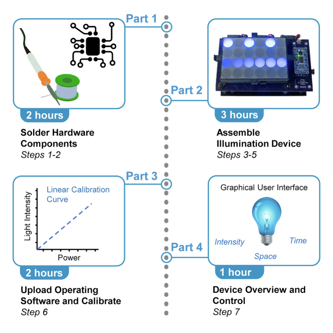
Optogenetic modulation of protein interactions enables spatiotemporal control of cellular signaling dynamics in a variety of biological systems. However, light patterning by standard microscopes is limited by their complexity, sample throughput, and cost. To address the need for low-cost, user-friendly, and high-throughput photopatterning, we have engineered devices for light activation at variable amplitudes (LAVA). This protocol describes the assembly of LAVA devices, which enable spatial and temporal control of optogenetic stimulation and cellular signaling dynamics in multiwell cell culture plates.
For complete details on the use and execution of this protocol, please refer to Repina et al. (2020).
Graphical Abstract
Highlights
-
•
Fabrication of illumination devices for light activation at variable amplitudes (LAVA)
-
•
Spatiotemporal control of light illumination in multiwell cell culture plates
-
•
Overview of optogenetic photostimulation and analysis in LAVA devices
Optogenetic modulation of protein interactions enables spatiotemporal control of cellular signaling dynamics in a variety of biological systems. However, light patterning by standard microscopes is limited by their complexity, sample throughput, and cost. To address the need for low-cost, user-friendly, and high-throughput photopatterning, we have engineered devices for light activation at variable amplitudes (LAVA). This protocol describes the assembly of LAVA devices, which enable spatial and temporal control of optogenetic stimulation and cellular signaling dynamics in multiwell cell culture plates.
Before You Begin
This protocol will provide the step-by-step instructions to fabricate the default blue-light LAVA board described in Repina et al, 2020. All design files, custom parts, and operating software are provided, and no electrical or coding experience is required for fabrication. Before starting LAVA board fabrication, you must first assemble all of the necessary materials, equipment, and custom ordered parts. Custom orders include the printed circuit boards, 3D-printed light guides, laser-cut components, and photomasks. Figure 1 outlines the major components of the 24-well LAVA board. 96-well LAVA boards share all of the same components, excluding custom parts 1, 3, 5, and 6.
Figure 1.

Major Components of LAVA Board Device Fabrication
24-well LAVA board depicted. All parts are identical between the 24-well and 96-well LAVA boards, excluding parts 1, 3, 5, and 6.
Order Custom Materials
-
1.Printed circuit boards PCB-1 and PCB-2 (Figure 1, parts 6 & 12)
-
a.EAGLE and Gerber files for all printed circuit boards (PCBs) are provided here: https://github.com/LAVAboard/LAVA/tree/master/CircuitBoard
-
b.Parts can be ordered from any PCB manufacturer. We recommend OSH Park, www.oshpark.com
-
i.Silk screen stencils are very helpful during reflow soldering. We recommend ordering a silk screen mask for PCB-1 from your preferred PCB manufacturer or OSH Stencils, www.oshstencils.com
-
i.
-
a.
-
2.3D-printed light guides (Figure 1, part 3 & 5)
-
a.STL files for all light guides are provided here: https://github.com/LAVAboard/LAVA/tree/master/LightGuides
-
b.Components can be printed on any extrusion-based 3D printer (ex. Ultimaker 3, uPrint, etc) out of black PLA or ABS. No support material is required during printing.
-
a.
-
3.Laser-cut components (Figure 1, parts 9, 15, & 17)
-
a.AI files for all laser-cut components are provided here: https://github.com/LAVAboard/LAVA/tree/master/LaserCut
-
b.Components should be cut out of 0.118” (3 mm) thick acrylic.
-
a.
-
4.Photomasks
-
a.Custom photomasks can be cut from adhesive vinyl using a dye cutter.
-
b.Custom photomasks can be laser-plotted from mylar using a photomask print service such as www.fineline-imaging.com.
-
c.Custom photomasks can be printed onto transparency film using a standard inkjet printer. Note, you may need to stack multiple transparencies for high opacity.
-
a.
-
5.Power supply (PSU)
-
a.Choice of correct power supply is critical for proper LAVA board operation. Please see the Key Resources Table for the suggested power source to use with blue CLM1B Cree Light Emitting Diodes (LEDs). For use with other LEDs, perform the following calculation to determine the power supply unit (PSU) voltage, note Vf is the forward voltage of a single LED (usually 2–5 V). Please note that PSUs that exceed this calculated voltage by greater than 1–2 V will cause overheating of the TLC5947 chip.
-
i.PSU voltage (24-well board) = 5 x Vf
-
ii.PSU voltage (96-well board) = 4 x Vf
-
i.
-
b.For the default design, each LAVA board LED receives a 15 mA current and voltage equal to Vf for the respective format. Thus, the power supply for each board is
-
i.24-well board: 18-Watt 18V 1200 mV AC-DC Wall Adapter (Key Resources Table)
-
ii.96-well board: 18-Watt 15V 1500 mA AC-DC Wall Adapter (Key Resources Table)
-
i.
-
a.
-
6.Assemble all other materials and equipment
-
a.See the Key Resources Table and Materials and Equipment sections below.
-
a.
CRITICAL: Be sure to choose the correct power supply for either the 24-well board or the 96-well board. Beware, if PSU output voltage is more than 1–2 V greater than the calculated voltage above, the TLC5947 may overheat. Always test the PSU by running the LAVA board with the selected PSU for >10 min and check that the TLC5847 chip does not become hot.
Key Resources Table
| REAGENT or RESOURCE | SOURCE | IDENTIFIER |
|---|---|---|
| Software and Algorithms | ||
| JarJarBlinks GUI | GitHub | https://github.com/LAVAboard/LAVA |
| LED calibration code | GitHub | https://github.com/LAVAboard/LAVA |
| Other | ||
| Circuit board (PCB1) | Circuit board manufacturer | https://github.com/LAVAboard/LAVA/tree/master/CircuitBoard |
| Circuit board (PCB2) | Circuit board manufacturer | https://github.com/LAVAboard/LAVA/tree/master/CircuitBoard |
| Raspberry Pi Zero W | Adafruit | Cat#3400 |
| Adafruit 24-Channel 12-bit PWM LED Driver TLC5947 | Adafruit | Cat#1429 |
| SanDisk 8GB microSD High | Amazon | N/A |
| Arctic Silver 7 g Thermal Cooling Adhesive Set | Amazon | Cat#ASTA-7G |
| Cree SMD Blue 470 nm LED | Mouser | Cat#CLM1B-BKW-CTBVA353CT-ND |
| Fan Axial 40 × 10.5 mm 12 V DC wire | Digikey | Cat#1053-1206-ND |
| Bracket universal 0.628 × 0.628 inch | Digikey | Cat#36-618-ND |
| Terminal block RCPT 2POS VERT 0.100 | Digikey | Cat#A121350-ND |
| Non-Isolated POL DC/DC Converter, 1 Output, 12 W, 12 V, 1 A, Fixed, Through Hole | Mouser | Cat#495-TSR-1-24120 |
| Non-Isolated POL DC/DC Converter, 1 Output, 5 W, 5 V, 1 A, Fixed, Through Hole | Mouser | Cat#495-TSR-1-2450 |
| Slide Switch, On-None-On SPDT | Mouser | Cat#612-500SSP1S4M6QEA |
| Rubber Push-in Bumper, Tight-Grip Ridged Stem, 1/4 inch Hole Size, 9/16 inch Diameter | McMaster Carr | Cat#9309K16 |
| Nylon 6/6 Plastic Hex Standoff, 3/16 inch Hex, 7/16 inch Long, 2-56 Female Thread | McMaster Carr | Cat#92319A255 |
| Nylon Pan Head Screws, Phillips, 2-56 Thread, 3/16 inch Long | McMaster Carr | Cat#94735A706 off-white |
| Vibration-Damping Sandwich Mount with Insert Neoprene, 8-32 Thread, 7 lb Capacity, 1/2 inch High | McMaster Carr | Cat#94955K21 |
| Female Threaded Round Standoff, 18-8 Stainless Steel, 1/4 inch OD, 1-1/4 inch Long, 8-32 Thread Size | McMaster Carr | Cat#91125A454 |
| 18-8 Stainless Steel Cup-Point Set Screw, 8-32 Thread, 1/2 inch Long | McMaster Carr | Cat#92311A194 |
| Black-Oxide 18-8 Stainless Steel Pan Head Phillips Screws, 6-32 Thread, 5/8 inch Long | McMaster Carr | Cat#91249A151 |
| Black-Oxide 18-8 Stainless Steel Pan Head Phillips Screws, 8-32 Thread, 1/4 inch Long | McMaster Carr | Cat#91249A189 |
| 18-8 Stainless Steel Hex Nut, 6-32 Thread Size | McMaster Carr | Cat#91841A007 |
| 18-8 Stainless Steel Hex Nut, 8-32 Thread Size | McMaster Carr | Cat#91841A009 |
| 70 mm × 130 mm Rectangular Heat Sink - 1.4°C/W | Luxeon Star | Cat#N13070-40B |
| 18 W, 18 V AC-DC High Reliability Industrial Wall Adapter 2.1 mm Plug Level VI (24-well device) | Jameco | Cat#2225625 |
| 18 W, 15 V AC-DC High Reliability Industrial Wall Adapter 2.1 mm Plug Level VI (96-well device) | Jameco | Cat#2225617 |
| DC Barrel Power Jack/Connector (5.5 mm jack, 2.1 mm center pole diameter) | Sparkfun | Cat#00119 |
| Break Away Headers - Straight, 40-pin, 0.1 inch spacing | Sparkfun | Cat#00116 |
| Female headers - 40-pin, 0.1 inch spacing | Sparkfun | Cat#00115 |
| Acrylic Sheets, 14 × 14 inch, 0.118 inch thick | Any plastics supplier (ex. TAP Plastics) | N/A |
| 80° Light Shaping Diffuser on 0.010 inch Polycarbonate, 24 × 24 inch | Luminit | Cat#L80P1-24 |
| Recommended Cell Culture Plates | ||
| CELLSTAR™ 96 Well μClear Black Flat-Bottomed Microplates | Greiner Bio-One | Cat#688089 |
| Cell imaging plate,24-well Black Plate with 170 μm glass bottom | Eppendorf | Cat#30741021 |
| VisiPlate-24 Black, Black 24-well Microplate with Clear Bottom | Perkin Elmer | Cat#1450-605 |
Note: Other 24-well and 96-well cell culture plates can be used with the default LAVA board devices. We recommend glass bottom or thin plastic. We also recommend black-walled imaging plates to minimize any light contamination between adjacent wells. You may need to modify the 3D-printed light guide design if the plate does not fit the current dimensions.
Materials and Equipment
| Tool | Note |
|---|---|
| Standard soldering toolkit | For standard through-hole soldering |
| Wire cutter | For fan attachment |
| Wire striper | For fan attachment |
| Phillips head screwdriver | Various applications |
| Mini flathead screwdriver | For fan attachment |
| Tweezers | For LED placement |
| Scissors | For diffuser preparation |
| Super glue | For LED driver cover |
| Squeegee | For reflow soldering and epoxy application |
| Hot plate or reflow oven | For reflow soldering. A reflow oven can also be used. |
| Laser cutter | Any laser cutter capable of cutting 12 x 12 x ¼” acrylic sheets is sufficient. Parts can also be outsourced to a laser cutting service. |
| 3D printer | Any 3D printer capable of printing black PLA or ABS parts with at least 6 x 6 x 6” bed size is sufficient. No support material required. Parts can also be outsourced to a 3D printing service |
| Compact Power Meter Console | For LED calibration and periodic evaluation of device performance. We recommend Thorlabs Cat#PM100D |
| Standard Photodiode Power Sensor | For LED calibration and periodic evaluation of device performance. We recommend Thorlabs Cat#S120C |
Step-By-Step Method Details
Step 1: Solder LEDs onto PCB-1 Using Reflow Soldering
Timing: 1 h
In this step, you will attach all of the LEDs onto PCB-1 via reflow soldering. Reflow soldering is a fast and simple way to attach surface-mount components to a circuit board. In brief, reflow solder paste is applied to the copper pads on PCB-1. The LEDs are placed on top of the paste and the board is heated on a hot plate to melt and solidify the solder. We recommend the following guide as a reference: https://www.build-electronic-circuits.com/reflow-soldering/.
-
1.
Using the soldering mask, apply reflow solder paste only to the grid pattern of the copper pads on PCB-1 (Figure 2A). Make sure paste application is clean and there is no runoff connecting any pads. Clean up overflow with a paper towel if necessary.
Figure 2.

Workflow to Reflow Solder LEDs onto PCB-1 for the 24-Well LAVA Board Format
(A) Representative image of soldering paste application to PCB-1.
(B) Representative image of LED placement onto PCB-1.
(C) Example of correct CLM1B Cree LED placement. Anode marking must face top left. For 24-well LAVA board, each well is illuminated with a cluster of five LEDs connected in series. Single LED circled in red.
(D) Schematic of a single LED denoting proper orientation.
(E) Schematic of solder pad placement on PCB-1. All dimensions are in inches.
-
2.
With tweezers, place surface-mount LEDs onto the pads in the correct orientation (angled notch indicating anode must be on top left) (Figures 2B−2D).
-
3.
Place PCB-1 onto the hot plate and heat on maximum temperature for 2–5 min. Inspect LED alignment and adjust with tweezers if necessary. Once you notice the solder paste turn a metallic color, wait an additional 1–2 min. Carefully and safely remove board from the hot plate and let cool at room temperature for 5–10 min.
-
4.
Clean the solder mask with a paper towel and save for future use.
Note: If using LEDs other than the blue-light LEDs specified in the Key Resources Table, they must be package PLCC-4 or PLCC-2. Note that the notch indicator standards may vary between manufacturers, so be sure to place the LED onto the pads in the correct orientation. We highly recommend testing a single LED prior to soldering the entire PCB-1 to ensure proper orientation.
Step 2: Solder Through-Hole Components Using Standard Soldering
In this step, you will attach all of the through-hole components to PCB-1 and PCB-2 via standard soldering techniques. The placement for all remaining through-hole components is marked on PCB-1 and PCB-2. The component outline indicates the side (PCB top vs. bottom) onto which the component should be physically placed. The leads of the component pass through the matching holes, and the component is soldered on the opposite side from that on which it is physically placed. While soldering, make sure that each component is flush with the PCB.
If a component is accidentally soldered in the wrong orientation, it should be removed with de-soldering braid or a solder sucker and re-soldered correctly. We recommend this Sparkfun guide as a reference for soldering techniques: https://learn.sparkfun.com/tutorials/how-to-solder-through-hole-soldering/all
-
5.Solder the following electrical components onto PCB-1, ensuring proper orientation:
-
a.Fan terminal blocks (×3).
-
i.Solder with the wire opening facing outward (as indicated in Figures 3A and 3B).
-
i.
-
a.
Figure 3.

Representative Images for the Step-by-Step Attachment of Each Electrical Component to PCB-1 via Standard Soldering Techniques
(A and B) (A) Fan terminal block insertion and (B) orientation.
(C) Female headers cut to the insert dimensions and every 4th pin removed.
(D) Male headers with every 4th pin removed and inserted into female headers.
(E−G) (E) LED Driver orientation with (F) top soldering, and (G) bottom soldering.
(H) Male power and data transfer header orientation.
-
b.LED driver (TLC5947).
-
i.First, solder female headers onto PCB-1. You will need ×4 15-pin headers and ×1 6-pin header. To match the hole pattern, you will need to gently pull out every 4th pin from the headers with plyers (Figure 3C).
- ii.
- iii.
-
iv.Flip PCB-1 and solder the bottom leads (Figure 3G). Be sure not to short any of the connections.
-
i.
-
c.Power and data transfer headers (×2 4-pin male headers). Ensure correct placement of these headers and solder (Figure 3H).
-
b.
-
6.Solder the following electrical components onto PCB-2, ensuring proper orientation:
-
a.Power and data transfer headers (×2 4-pin female headers, as indicated in Figure 4A).
-
a.
Figure 4.

Representative Images for the Step-by-Step Attachment of Each Electrical Component to PCB-2 via Standard Soldering Techniques
(A) Female power and data transfer headers.
(B and C) (B) DC barrel plug connector orientation and (C) attachment.
(D) TRACO TSR 1-2450 power voltage regulator.
(E) TRACO TSR 1-24120 power voltage regulator.
(F) Female header orientation on bottom of PCB-2.
(G) Raspberry Pi Zero W orientation at bottom of PCB-2 and attached via male headers.
-
b.DC barrel plug connector (Figures 4B and 4C).
-
c.5V and 12V voltage regulators (TRACO power). Ensure polarity indicator (dot) lines up with indicator dot on PCB-2 (Figures 4D and 4E).
-
d.SPDT power switch (location marked on PCB-2).
-
e.Raspberry Pi Zero W
-
i.First, solder female headers onto PCB-2 (×2 20-pin female headers, as indicated in Figure 4F).
-
ii.Then, place male headers into the soldered female headers. Place Raspberry Pi Zero W through these male headers (ensure proper orientation, as indicated in Figure 4G) and solder the leads.
-
iii.Lastly, secure the Raspberry Pi to PCB-2, and secure PCB-2 to PCB-1, using the hexagonal plastic standoffs (×8) and 2–56 screws (×16). Ensure that the corresponding headers mate together between PCB-1 and PCB-2.
-
i.
-
b.
Step 3: Attach Heat Sink to PCB-1
In this step, you will attach a heat sink to bottom of PCB-1. The heat sink acts to draw away and disseminate the heat generated by the LEDs. This is necessary for long-term use, to prevent overheating and increase device lifespan.
- 7.
Figure 5.

Representative Images to Attach Heat Sink to PCB-1
(A and B) Activated epoxy addition to (A) heat block and (B) copper region of PCB-1.
(C) Depiction of attachment orientation
-
b.Sandwich the head sink and PCB-1 surfaces (Figure 5C).
-
c.Make sure heat sink is centered and wait 1 h or more to solidify.
-
b.
Step 4: Assemble Laser-Cut and 3D-Printed Components
In this step, you will begin to assemble the non-electrical components of the LAVA board. A schematic of the laser-cut base (Figure 1, part 9) is represented in Figure 6A. Note that this part is not symmetric, and the square orientation indicator marks the left side of the base, as viewed by looking at the top of the LAVA device. A schematic of the laser-cut fan holder (Figure 1, part 15) is depicted in Figure 6B. These custom laser-cut components are designed to compactly and efficiently house the electrical components and heat block.
- 8.
Figure 6.

Schematics of Laser-Cut Components for LAVA Board Base Structure
(A) Schematic of laser-cut base with color-coded depiction of each hole component.
(B) Schematic of laser-cut fan holder with color-coded depiction of each hole component.
Figure 7.

Representative Images for Step-by-Step Assembly of LAVA Board Base Components
(A and B) Rubber foot peg (A) part and (B) orientation from the bottom.
(C) Vibration-damping mount orientation.
(D) 8-32 set screw orientation.
(E) Round metal standoff orientation.
(F) Attachment of fans to laser-cut holder.
(G) Fan orientation, arrow corresponding to air flow.
(H) Attachment of fan block to base.
(I) Fan block and base orientation with optimal wire cut length and exposure.
-
9.Assemble and attach fan components
- a.
- b.
-
10.
Assemble the walls of the LED driver cover (Figure 1, part 17) using superglue. The cover will be placed on top of the LED driver to prevent accidental shortage.
-
11.
Cut the 80˚ LSD diffuser sheet to match the 3D-printed light guides. Cut one diffuser to fit between the two light guides (Figure 1, part 4, 4.5 × 3.0 inch) and one for the top light guide (Figure 1, part 2, 4.8 × 3.3 inch).
Step 5: Attach the LAVA Electronics to the Remaining Hardware Components
In this step, you will attach all of the remaining electrical components to the LAVA board base and complete the hardware fabrication portion of the design.
-
12.Attach PCB-1 and light guide to LAVA board base.
-
13.
Insert fan wires into the corresponding terminal block, ensuring correct orientation, and tighten set screw with small flathead screwdriver.
-
14.
Add the intermediate diffuser (Figure 1, part 4) on top of the bottom light guide (Figure 1, part 5) and sandwich between the top light guide (Figure 1, part 3). Place the final diffuser (Figure 1, part 2) onto the top light guide. 3D-printed light guides should click together, though you may need to apply some force.
Pause Point: At this point, the LAVA board hardware components should all be assembled, and the hardware components of the device are complete. Step 6 can be completed at any time after device fabrication.
Step 6: Software Control of LAVA Board
In this step, you will upload the device operating software to the LAVA board, calibrate the LED output, and configure the provided GUI for spatiotemporal control of blue-light stimulation. We have provided the general software to initialize the LAVA boards and communicate between the GUI and Pi to upload patterns of continuous light, light pulses, or light functions. If you wish to customize the light presentation further, you may need to design your own code/GUI to control the LEDs and Pi. There are many resources available for Raspberry Pi programming; however, we anticipate that the provided software and GUI to satisfy most user needs.
-
15.Flash the operating software (OS) image to micro SD card.
-
a.Download the provided disk image (raspberrypi.dmg, 7.95GB file size) from https://github.com/LAVAboard/LAVA
-
b.Insert a blank 8 GB micro SD card into your computer.
-
c.Download a flash software. We recommend Etcher. https://www.balena.io/etcher/
-
d.Run Etcher and follow instructions to flash the OS disk image to the SD card. Be sure to select the correct target drive that corresponds to the SD card.
-
e.Insert the micro SD into the Raspberry Pi. Power LAVA board and wait 1 min for the Pi to turn on. The LED light sequence will change (ex. B01 blinks), and you will see APPLE_PI WiFi network appear. If not, the SD card flash was not successful.
-
a.
Note: Alternatively, you can use the command line to flash the disk image to the SD card. You will need to unmount the SD card and reformat as FAT32. This may take some time. Once complete, eject the card and insert into the Raspberry Pi micro SD slot.
-
16.LED light output calibration
-
a.In the following steps, the calibration script LED_calibration.py is run on the Raspberry Pi to calibrate the LED output. PWM values are sent to each well (starting with well A1, A2, etc.) and decrease sequentially from 4095 (maximum intensity) to 0 (off): 4095, 4000, 3800, 3600, 3400, 3200, 3000, 2800, 2600, 2400, 2200, 2000, 1800, 1600, 1400, 1200, 1000, 800, 600, 400, 200, 0. For each PWM value and each well, the illumination intensity should be recorded with a power meter. The script is configured to allow the user 20 s to align the power meter and 5 s to record each PWM measurement. These settings can be changed as desired by opening the LED_calibration.py and changing sleep() values.
-
b.Power the LAVA device and connect to APPLE_PI WiFi network (password: raspberry)
-
c.Wirelessly SSH into the Pi. In Mac use Terminal, or in Windows download a BASH terminal (we recommend ubuntu, https://ubuntu.com/). Enter the following into the command line:
-
i.ssh pi@192.168.4.1
-
ii.password = raspberry
-
i.
-
d.Stop the LED driver process on the Pi. Enter the following into the command line:
-
i.htop.
-
ii.record the PID corresponding to the LED driver (see “Command’ column”). Execute the following command, and substitute ‘PID’ with the recorded number.
-
iii.sudo kill PID.
-
i.
-
e.Now run the following python script. Run the internal python calibration code by entering.
-
i.python LED_calibration.py
-
ii.To view or modify this file, enter nano LED_calibration.py
-
i.
-
f.Record the light intensity data for each PWM with a power meter. In the terminal, you should see the 12-bit PWM currently being executed.
-
g.Generate the calibration curve where the X-axis is PWM (0-4095) and Y-axis is measured light intensity (μW/mm2). Convert the light intensity recorded into μW/mm2 (depending on the area of the measurement probe). An example calibration data is depicted in Figures 8A and 8B.
-
a.
Figure 8.

Example CLM1B Blue LED Calibration Curve
(A) Calibration curve for 24-well LAVA board with two different light guide thicknesses.
(B) Calibration curve for a 96-well LAVA board. Light intensity recorded using a PM100D compact power and energy meter console (Thorlabs) with a standard photodiode power sensor (S120C, Thorlabs). Curve slope and y-intercept used in software design to designate individual well intensity.
-
h.Apply a linear trend and record the slope (m) and y-intercept (b) for later use.
-
h.
Optional: Change the name of the WiFi network (default is APPLE_PI).
-
a.Power the LED board and connect to APPLE_PI WiFi network (password = raspberry).
-
b.Wirelessly SSH into Pi (see step 6.16c).
-
c.Configure the access point host software (hostapd) by entering
-
i.sudo nano/etc/hostapd/hostapd.conf
-
ii.Change the ssid to desired WiFi name. Do not modify any other lines.
-
i.
-
d.Use the keyboard combination ctrl-O then “enter” to save the file, then ctrl-X to exit the nano text editor.
-
e.Reboot the Pi and you will see the new Wifi name appear. Enter
-
i.sudo reboot
-
i.
-
a.
Note: At this point, the LAVA device fabrication is complete. LAVA device illumination accuracy should be monitored every 3–6 months with a power meter. Re-calibrate if necessary (step 6.16)
Step 7: Optogenetic Cellular Experiments with LAVA Boards
The LAVA boards are versatile, user-friendly devices that are useful for numerous optogenetic experiments in 24- and 96-well plate formats. The provided GUI (JarJarBlinks) offers precise control of LED light intensity and timing over the entire length of an experiment. LAVA boards can be placed directly in any standard incubator and can run for any duration of experiment. Typical LAVA boards last at least 6 months in an incubator environment and are easy to replace. In this step we will outline the GUI control of LAVA boards and generic protocols for continuous, pulsed, and dynamic optogenetic experiments.
-
17.GUI control and pattern upload
-
a.Turn on LAVA board and wait ~1 min for boot to complete.
-
b.Connect to the LAVA board WiFi network (default = APPLE PI) and set up the wireless SSH connection at least once (see step 6.16c).
-
i.You can connect to the LAVA board just by selecting the Pi WiFi network (password = raspberry) from this point forward, no need to SSH.
-
i.
-
c.Download JarJarBlinks.jar here https://github.com/LAVAboard/LAVA
-
d.Open the JarJarBlinks application, choose the correct plate format, and enter the slope (m) and y-intercept (b) from the LED calibration (step 19b). Be sure to use the calibration values for the corresponding LAVA board format and light guide thickness.
-
e.Configure the pattern to be uploaded.
-
i.Continuous illumination: Choose the “Const” designation for each well of interest. Enter the light intensity I in the open column (default device rang from 0.0 – 20.0 μW/mm2).
-
i.
-
a.
Note: continuous intensity above 2.0 μW/mm2 may exhibit cellular toxicity.
-
ii.Pulsed illumination: Choose the “Blink” designation for each well of interest. Enter the Imin (typically 0.0) and Imax (experiment dependent). Enter the duty cycle (percentage of time “on” per period) and period (in seconds).
-
ii.
Note: for CRY2 applications, the signal can be pulsed every 10 min, corresponding to the twice the half-life of cluster dissociation. If using another optogenetic system, make sure to characterize the association kinetics for your system to determine the minimum period necessary for your application. In comparison to continuous illumination, higher Imax intensities can be used for pulsed illumination while avoiding phototoxicity.
-
iii.Complex illumination patterns: Choose the “Func” designation for each well of interest. Enter the linear or sinusoidal function parameters of interest and for desired time interval. When complete, select “add” function. Multiple functions can be combined to generate complex temporal light patterns.
-
iii.
-
f.Upload experiment pattern to LAVA board device by selecting the “Submit and Upload” button at the bottom of the screen.
-
i.If successful, the pattern should upload and appear within 5 s.
-
i.
-
g.Begin cellular experiment with optogenetic pattern. After seeding the cells on the recommended imaging plates (Key Resources Table), place the plate directly on the LAVA board when you want to begin illumination and place the device in the incubator for long-term culture.
-
h.After illumination, end-point analysis, such as immunostaining, flow cytometry, or transcriptomics analysis, can be performed.
Note: Java 8 or above must be installed on your computer to open the JarJarBlinks application. Additionally, we recommend storing the LAVA board outside of the incubator when not in use, although continuous storage inside the incubator is also possible.
Expected Outcomes
Successful execution of this fabrication protocol will produce a fully functional LAVA board illumination device (Figure 1). The default LAVA devices are capable of controlling blue-light intensity and timing for a multitude of potential applications in optogenetic experiments. The addition of user-defined photomasks allows for spatial control of blue-light activation. LAVA boards can operate in any standard incubator or benchtop environment. LAVA boards are easily incorporated into standard cell culture formats or protocols to enable high-throughput optogenetic experimental design without the need for a conventional microscope. Broader applications of LAVA board devices include spatiotemporal control of protein activation, localization, presentation, channel manipulation, gene expression, and other novel optogenetic toolkits. For a complete investigation into device design, characterization, and utilization, please refer to Repina et al., 2020.
Limitations
This protocol describes assembly of the default LAVA devices to control blue-light photopatterning of Cryptochrome-2 (Cry2) (Repina, et al., 2020). For application to other optogenetic systems, the blue LEDs can be readily substituted with other wavelengths, such as UV, green, red, or far-red. Depending on the physical dimensions and forward voltage of the LED, PCB-1 and power supply choice may need to be modified. In addition, default LAVA devices are only capable of controlling a single LED color but can be extended to multicolor applications by using multiple TLC5947 chips. Additionally, we have only provided design materials for 24-well and 96-well LAVA board devices. Any other plate format will require modifications to the PCB-1 layout and the 3D-printed light guides. Also, due to the 24-channel limit of the TLC5947 chip, the current 96-well LAVA device cannot control each individual well, but instead four wells that are connected in series (2 sets of 4 for each column, 24 variable well formats per plate). Lastly, the LAVA board is most compatible with end-point measurements, such as fixation and immunostaining, or harvesting of cells for flow cytometry or transcriptomic analysis. The device could be used for live real-time imaging with an upright microscope, however the microscope sample stage or optical configuration may need to be adapted to accommodate the LAVA board.
Troubleshooting
Problem
Light guides do not snap together or fit to desired TC plate
Potential Solution
We tried to design the light guides to accommodate most 3D printers and TC plate formats. However, due to variabilities between 3D printers, parts may not fit together properly. We provide the SolidWorks files for the 3D printed components that can be modified to fit different 3D printers and use cases.
Problem
I assembled the LAVA device, plugged it in, and nothing turns on!
Potential Solution
The things that should initially turn on are: the fans, LED indicators on TLC5947 board, and the LEDs. If nothing turns on, make sure the power supply is plugged in and power switch is in the ‘on’ orientation. If the LEDs do not turn on, verify that they are soldered in the correct orientation and, using a volt meter, that power is being delivered to them.
If the LEDs turn on but fans do not, verify that you are using the correct power supply. The fans are powered with 12V through a DC voltage regulator (TSR-1-24120). For them to power on, the power supply must be at least 15V. If you are using LEDs with a low forward voltage and your power supply is lower than this value, then you can either (1) power the fans directly from the power supply if the power supply provides 12V or lower, or (2) use a different DC voltage regulator that takes a lower input voltage, such as TSR 1-2490. For option (1), solder a wire from the positive terminal of the barrel plug connector to the positive fan terminal. For option (2), replace the TSR-1-24120 with TSR 1-2490. This will provide 9V to the fans, driving them at a slower speed but will still be sufficient for cooling.
For the Raspberry Pi to turn on, the user must proceed with the software configuration and installing the Raspberry Pi SD card.
Problem
I downloaded JarJarBlinks.jar but it does not open
Potential Solution
Ensure that Java and Java SE Development Kit (JDK) 8 or higher is installed on your computer
Problem
The LED output is not bright enough for activating my optogenetic system
Potential Solution
The TLC5947 chip delivers 15 mA to each of the 24 channels. The output can be increased to 30 mA by soldering an additional 3.3 kOhm through-hole resistor onto the TL5947 chip (see the TLC5947 datasheet and Adafruit page for more details: https://www.ti.com/lit/ds/symlink/tlc5947.pdf, https://www.adafruit.com/product/1429). This will approximately double the light output. Furthermore, the lightguide thickness and number of diffusers can be reduced at the expense of illumination uniformity. Lastly, the light guides can be spray-painted with reflective paint to reduce light absorption by the black plastic.
Problem
I accidentally plugged in the wrong PSU, what should I do?
Potential Solution
If the LAVA device still turns on and patterns are able to be uploaded, then the device is fully operational. If the device overheated, the TLC5947 chip likely needs to be replaced. The chip is easily removable as it is secured to the board with removable headers. Detach the damaged TLC5947 chip and insert a new chip with soldered headers (Figures 3E and 3F). To verify board functionality, the accuracy of the light output should be verified with a power meter, and re-calibrated if necessary (step 6.16).
Problem
After long-term use, LAVA device stops displaying uploaded patterns
Potential Solution
After months of use in a 37°C humidified incubator, the TLC5947 chip or Raspberry Pi microcontroller may stop functioning properly. Verify that LED indicators are functioning as normal. If not, we recommend replacing both components. They are connected to PCB-1 and PCB-2 via headers to enable quick replacement.
Problem
I smell a burning smell, what is happening?
Potential Solution
Likely an electrical component was shorted because it was soldered in the wrong orientation, or a piece of metal or aluminum foil touched the electrical components and caused a short. If this occurs, we recommend replacing the TLC5947 chip and Raspberry Pi as described above.
Resource Availability
Lead Contact
Further information and requests for resources and reagents should be directed to and will be fulfilled by the Lead Contact, David V. Schaffer (schaffer@berkeley.edu).
Materials Availability
All custom design files and necessary materials can be found at https://github.com/LAVAboard/LAVA
Data and Code Availability
All custom code and device operating software can be found at https://github.com/LAVAboard/LAVA
Acknowledgments
We thank Christopher Myers, Mitchell Karchemsky, and Rundong Tian at the UC Berkeley CITRIS Invention Lab for assistance and discussions of rapid prototyping design and techniques. We also thank Danqing Zu and Xiaoping Bao for help with device fabrication and photographs. Funding supporting this work was provided by the U.S. National Institutes of Health (R01NS087253 to D.V.S.), the U.S. National Science Foundation (to N.A.R. and H.J.J.), and the Siebel Scholars Foundation (to N.A.R.).
Author Contributions
N.A.R. conceived the study, designed devices and performed experiments, performed analysis, and wrote the manuscript. H.J.J. performed experiments and wrote the manuscript. T.M. designed software control and the graphical user interface. R.S.K. conceived the study. D.V.S. conceived the study and wrote the manuscript.
Declaration of Interests
N.A.R., T.M., and D.V.S. are co-inventors on related intellectual property.
Contributor Information
Hunter J. Johnson, Email: hunter.johnson@berkeley.edu.
David V. Schaffer, Email: schaffer@berkeley.edu.
References
- Repina N.A., McClave T., Johnson H.J., Bao X., Kane R.S., Schaffer D.V. Engineered illumination devices for optogenetic control of cellular signaling dynamics. Cell Reports. 2020;37:107737. doi: 10.1016/j.celrep.2020.107737. [DOI] [PMC free article] [PubMed] [Google Scholar]
Associated Data
This section collects any data citations, data availability statements, or supplementary materials included in this article.
Data Availability Statement
All custom code and device operating software can be found at https://github.com/LAVAboard/LAVA