

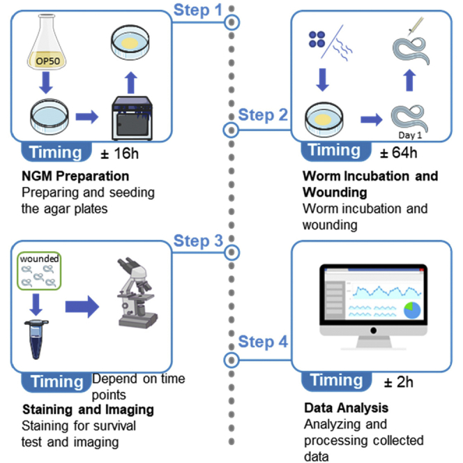
Summary
Efficient membrane repair after injury is essential for cell and animal survival. Caenorhabditis elegans epidermal cell hpy7 has emerged as a powerful genetic system to investigate the molecular mechanism of membrane repair in vivo. This protocol describes detailed approaches for how to perform wounding on the epidermis and how to examine membrane repair by trypan blue staining, confocal imaging, and data analysis.
For details on the use and execution of this protocol, please refer to Meng et al. (2020).
Subject Areas: Cell Biology, Cell Membrane, Model Organisms
Graphical Abstract
Highlights
-
•
Protocol for needle-induced wounding in C. elegans epidermis
-
•
Tips on how to use C. elegans epidermis for membrane repair
-
•
Diverse assays for measuring the consequence of membrane repair
Efficient membrane repair after injury is essential for cell and animal survival. Caenorhabditis elegans epidermal cell hpy7 has emerged as a powerful genetic system to investigate the molecular mechanism of membrane repair in vivo. This protocol describes detailed approaches for how to perform wounding on the epidermis and how to examine membrane repair by trypan blue staining, confocal imaging, and data analysis.
Before You Begin
Refer to www.wormbook.org for information related to the basic biology of Caenorhabditis elegans, including their cell biology, germline, phenotypes of each life stage, genetics, and many more.
Culturing Escherichia coli Bacteria OP50
Timing: 10–12 h
OP50 is used to feed C. elegans in the Nematode Growing Medium (NGM).
-
1.
Use 50 mL container to put 35–40 mL of B broth to a 50 mL container. Here, we used 50 mL centrifuge tube.
-
2.
Use a separate tube to put 5 mL of B broth as a control.
-
3.
Mix in a single colony of OP50 into the broth.
Note: A tiny amount will do since it will be incubated to proliferate
-
4.
Put the tube into a shaking incubator overnight at 37°C.
Note: Do not close the cap too tightly.
-
5.
OP50 is ready to be used or can be stored in 4°C for at least 1 month.
Note: Use a control group to make sure that the B broth used is not contaminated in the first place. If the color of the solution used as a control turned foggy/milky, the stock solution might be contaminated.
CRITICAL: Perform all the experiments inside a ventilator. All of the tubes must be exposed to UV light for at least 15 min to sterilize. This is very crucial since the B broth has no antibiotics in it.
Nematode Growing Medium (NGM)
This medium is required as a medium to incubate C. elegans. This protocol is for preparing 1 L of NGM agar. The measurements can be scaled accordingly, depending on the total volume desired.
-
6.
Prepare a Volumetric flask, stir bar, magnetic stirrer, digital weighing scale, spoon, and aluminum foil.
-
7.
Measure 500 mL of dH2O as a starting solvent.
-
8.
Weigh 2.9 g of NaCl, 20 g agar, and 2.5 g peptone. Then, add to the flask.
-
9.
Turn on the magnetic stirrer wait for 2 min, then add in the other half ddH2O volume.
-
10.
Cover the flask with aluminum foil and Autoclave for 50 min.
-
11.
After autoclaving is finished, wait to cool until approximately 50°C.
-
12.
Add 1 mL of 1 M CaCl2, 1 mL of 1 M MgSO4, and 25 mL of 1 M KH2PO4.
-
13.
Swirl to mix well.
-
14.
Dispense the solution into agar plates, and wait until the solution solidifies.
-
15.
Using a pipette, drop 100 μL of OP50 Broth to each agar plate.
Note: Be sure to spread the OP50 well by tilting the petri dish.
-
16.
Tilt around the newly seeded NGM to let the OP50 spread evenly.
-
17.
Incubate the freshly seeded NGM plate in 37°C for another 6–8 h.
-
18.
The NGM is ready to be used to incubate C. elegans.
Worm Preparation
This step is crucial in every experiment that uses C. elegans a model. This protocol will give a guide in worm life stage synchronization by bleaching, planning experiments, and incubation until readily used at day 1 stage (L4 + 24 h).
-
19.
Prepare a 5% sodium hypochlorite bleaching solution.
-
20.
Prepare a 1.5 mL centrifuge tube, a 1,000 μL pipette, M9 buffer, and the fully grown worm plates that are going to be used for synchronization.
-
21.
Wash the plates by pipetting 1 mL of M9 buffer to a plate.
-
22.
Pipette in and out the M9 buffer from a plate. Make sure that most of the contents on the plate have been washed off.
-
23.
Pipette in the solution and use it for other plates. Repeat step 4 for all plates.
Tips: Notice that after washing several plates, the volume of M9 buffer will decrease. This is normal since some of the volumes will be trapped in the agar and are not sucked in with the pipette. To solve this, just add in more volume of M9 buffer for the next plates.
-
24.
After all, plates have been washed off, use the 1.5 mL centrifuge tube as a container. Then, put the tube inside the centrifuge machine. Centrifuge at 800 × g for 1 min.
Note: Placement of the EP tubes must be balanced on the opposite side. In case only one EP tube used for bleaching, use an EP tube filled with water for balance.
-
25.
Pipette out the supernatant. Be careful not to suck in the worms, which will sediment at the bottom of the EP tube.
Tips: After pipetting out most of the supernatant, try to use a smaller pipette to suck out the remaining supernatant.
-
26.
Add another 1 mL of M9 buffer to wash and centrifuge at 800 × g for another 1 min.
-
27.
Remove the supernatant. Then, add 1 mL of bleaching solution. Wait for 10 min while gently shaking the tube.
Note: You can put the EP tube to a shaking rack.
-
28.
After 10 min, Centrifuge at 800 × g for 1 min.
-
29.
Pipette all of the supernatants and wash them with 1 mL M9 buffer. Repeat on washing for 3× or until the smell of the bleaching solution is gone.
Note: This is important because only the eggs can resist the bleaching solution. Once they hatch, remnants of bleaching solution are lethal to the larvae.
-
30.
Pipette out most of the M9 buffer until ±300 mL volume remaining. Then, pour the solution to a fresh NGM plate.
Note: If the washed plates are egg-dense, separating them into several plates is an option.
-
31.
Incubate at 20°C–22.5°C until the day 1 stage.
Note: It would take ±64 h for C. elegans that are incubated at 20°C–22.5°C to reach the day 1 stage.
Note: Experiment can be planned maturely if the worms in a plate are in a synchronized life stage.
Note: Bleaching is also recommended to be done to overpopulated and dirty plates.
Transferring Worms
Maintaining healthy C.elegans is required in the entire course of the experiment. This step is used as a method used to prevent the worm from entering the dauer stage.
-
32.
Prepare a fresh NGM plate.
-
33.
Cut a small place from the overpopulated plate and put the piece to the fresh NGM plate.
Note: This simple step is very crucial to maintain healthy C.elegans when doing experiments.
Optional: use a worm picker to pick 5–10 young adult animals to the fresh NGM plate.
-
34.
Incubate the plate at 20°C–22.5°C incubator for maintaining worm population or for future experiments.
Note: Glass needle will be used as a tool to wound C. elegans (Figure 1).
Figure 1.

Image of Glass Capillary Puller
-
35.
Prepare a glass capillary and place it at the fixes of the puller.
-
36.
Set the starting temperature to 24.8°C by setting the knob at step 1, and set the no.1 heater temperature to 68.7°C.
-
37.
Press the start button, and the machine will pull automatically.
-
38.
Unscrew the fixes and carefully store the needle.
Note: Wounding needles can be prepared ahead for future uses.
Key Resources Table
| REAGENT or RESOURCE | SOURCE | IDENTIFIER |
|---|---|---|
| Chemicals, Peptides, and Recombinant Proteins | ||
| OP50 | CGC | N/A |
| B broth | Lab made | N/A |
| M9 buffer | Lab made | N/A |
| Bleaching solution | Lab made | N/A |
| Trypan blue | Sigma | Cat: T6146 |
| Agar powder | VETEC | LOT: #wxBc6612V |
| NaCl | Sinopharm Chemical Reagent Co. Ltd. | #10019318 |
| Peptone | Gibco | Lot: 0002391 |
| CaCl2 | Sinopharm Chemical Reagent Co. Ltd | #10005863 |
| Household bleach (5% solution of sodium hypochlorite) | N/A | N/A |
| Experimental Models: Organisms/Strains | ||
| N2 | CGC | N/A |
| Pcol-19-EFF-1::GFP (zjuSi28) II | Meng et al., 2020 | SHX788 |
| Pcol-19-tagBFP::syx-2(zjuSi72) IV | Meng et al., 2020 | SHX1025 |
| Recombinant DNA | ||
| Pcol-19-EFF-1::GFP | Meng et al., 2020 | pSX684 |
| pCFJ201-LoxP-SEC-Loxp-Pcol-19-tagBFP::3xFLAG::SYX-2 modified for CRISPR on ChrIV | Meng et al., 2020 | pSX1309 |
| pCFJ201-FRT-Hygro-FRT-Pcol-19-myr::mKate2 modified for CRISPR on ChrIV | Meng et al., 2020 | pSX850 |
| Pcol-19-EFF-1::GFP | Meng et al., 2020 | pSX684 |
| pCFJ201-LoxP-SEC-Loxp-Pcol-19-tagBFP::3xFLAG::SYX-2 modified for CRISPR on ChrIV | Meng et al., 2020 | pSX1309 |
| Software and Algorithms | ||
| ImageJ | National Institutes of Health | https://imagej.nih.gov/ij/ |
| GraphPad Prism 7.0 | GraphPad Software Inc. | https://www.graphpad.com |
| Microsoft Excel | Microsoft Corporation | https://www.microsoft.com |
| Other | ||
| Agar plate | N/A | N/A |
| Magnetic stirrer IKA® RH 2 | IKA | Model: RH B 2 S25 |
| Autoclave Machine | Zealway | GR60DA |
| Ventilator | N/A | N/A |
| Shaking incubator | N/A | N/A |
| Centrifuge 5424 | Eppendorf | N/A |
| Pipette tip blue 100–1,000 μL | ExCell Bio | #CS015-0012 |
| Pipette tip yellow 1–200 μL | ExCell Bio | #CS015-0013 |
| Pipette tip clear 0.1–10 μL | ExCell Bio | #CS015-0050 |
| Eclipse Ni-U (for trypan blue) | Nikon | N/A |
| CFI Plan Fluor 4× | Nikon | MRH00082 |
| CFI Plan Fluor 10× | Nikon | MRH00101 |
| Eclipse Ti-E (confocal microscope) | Nikon | N/A |
| CFI Plan Apochromat VC 100× Oil | Nikon | MRD01901 |
| CFI Plan Apochromat Lambda 10× | Nikon | MRD00105 |
| Cover Glass | Fisher Brand | Lot: 18937 |
| Oil | Nikon | Cat: 16484 |
| Glass slide | SAIL BRAND | Cat: 7105 |
| Eclipse Ni-U (for trypan blue) | Nikon | N/A |
| CFI Plan Fluor 4× | Nikon | MRH00082 |
| CFI Plan Fluor 10× | Nikon | MRH00101 |
| Eclipse Ti-E (confocal microscope) | Nikon | N/A |
| CFI Plan Apochromat VC 100× Oil | Nikon | MRD01901 |
| CFI Plan Apochromat Lambda 10× | Nikon | MRD00105 |
| Glass capillary | KWIK-Fil | Lot: 2112322 |
| Puller | NARISHIGE | Serial No: 16195 |
| Light microscope | Motic | SMZ-168 |
Materials and Equipment
| M9 Buffer | Final Concentration | Amount |
|---|---|---|
| NaCl | 0.008 M | 0.5 g |
| NH4Cl | 0.02 M | 1.0 g |
| Na2HPO4·7H2O | 0.02 M | 3.0 g |
| KH2PO4 | 0.02 M | 3.0 g |
| ddH2O | n/a | ~1,000 mL |
| Total | n/a | 1,000 mL |
| B Broth | Final Concentration | Amount |
|---|---|---|
| NaCl | 0.08 M | 5.0 g |
| Tryptone | 1% (mass/volume) | 10 g |
| ddH2O | n/a | ~1,000 mL |
| Total | n/a | 1,000 mL |
Note: These tables are for 1,000 mL of total volume. The amount of reagents added can be adjusted depending on the total volume to be prepared.
Note: Tryptone has hygroscopic property. To avoid clumps, avoid contact with water and close the lid immediately after use.
Note: Store these solutions at 22°C –26°C
Step-By-Step Method Details
Needle Wounding
A glass needle is used to wound the worm. This step is very crucial in analyzing the protein aggregation at the wound site.
-
1.
Grow the worm strain to be used in the experiment using the NGM plate in a 20°C incubator.
-
2.
Separate 20–30 L4 worms to a fresh NGM plate by picking them out of the master plate 1 day ahead of wounding.
Note: Separating worm will reduce the possibility for us to forget which worm we have wounded.
-
3.
30 min before wounding, place the NGM plate to be used for wounding on an icebox.
Note: This will reduce the movement of the worm, making wounding easier and more precise.
-
4.
Load the glass needle to a stable mount (Figure 2).
-
5.
Place the agar plate with worms to be wounded under a light microscope.
-
6.
Use low magnification and locate the glass needle, then lower the needle while increasing the magnification of the microscope while also gradually adjusting the focus.
-
7.
Position the needle perpendicular to the worm for wounding.
-
8.
Wound the worm around 1/3 from the head and 1/3 away from the tail, avoiding gonads. Make sure that the wound is punctured in hyp-7.
-
9.
Incubate the wounded animals and unwounded control animals at 20°C, waiting for the recovery (Figure 3).
Note: There are ways to confirm the worm is still alive:
-
10.
Check if the pharynx pump of the worm is still functioning.
-
11.
Test if the worm still responds to touch.
-
12.
Put a drop of water to the worm to see if there are any responds. (living worms will usually wiggle or swim).
Alternatives: Use automated micromanipulator and microinjector to perform precise needle wounding.
Figure 2.

Image of the Needle Mount
Figure 3.

C. elegans Diagram
Trypan Blue Staining
This experiment is used to observe the capability of membrane repair of a specific strain of worm. The staining will be done after needle wounding.
Note: Cell membrane will be breached when the worm is wounded
-
13.
A single worm can be wounded twice.
-
14.
Immediately put the wounded worms inside the TryB solution for 1 h incubation at 20°C.
-
15.
After 1 H, Pipette out most of the TryB solution out.
Note: Do not position the pipette tip at the very bottom. The worms may also be sucked into the pipette tip.
-
16.
Dilute with M9 buffer. (repeat washing process 3× or until the solution is clear-light blue) (Figure 4).
-
17.
Incubate the worms 20°C–25°C until the time point for imaging is reached.
-
18.
Observe the worms under a microscope. Here we used Nikon, Eclipse Ni-U.
Note: Wound site can be seen as a dark-blue spot while the healed wound will be light blue or even no staining can be observed.
Tips: 96 well plate is an option to be used if a large quantity of staining needs to be done
Note: To improve the reliability of the results, at least 100 worms are needed for the statistical analysis. Repetition of the experiment is also crucial
Alternatives: Use other membrane-impermeable fluorescent molecules to assess the damaged membrane.
Figure 4.

Washing Off TrypB Solution
The light-blue colored solution has been washed and is ready to be transferred to the NGM plate. The dark-blue solution shows the unwashed solution. The green arrow points to unwashed solution. The red arrow points to washed solution.
Single-Plane Imaging
-
19.
Prepare 4% melted agar and put it inside warmer to prepare the agar pad.
-
20.
Prepare four glass slides and construct as the picture show.
Note: This is to make an even surface of the agar pad (Figure 5).
Figure 5.

How to Assemble Glass Slides
-
21.
Use a dropper to drop a little melted agar to a cover slide and immediately cover it with another glass slide.
-
22.
Using 10 μL pipette put a drop of 12% levamisole on the agar pad.
-
23.
Pick the worms and group them on the levamisole for easier observation in the confocal microscope.
-
24.
Lay a coverslip on top of the agar pad and drop oil on the coverslip.
Note: Make sure that the oil has covered the area where the worms have been placed.
Note: The more detailed guide is available at IQ 3 user guide
-
25.Adjust the magnification, focus, and brightness to observe the worms
-
a.First, use 10× magnification to spot the worms. Use coarse Z plane adjustment to spot the position of the worm.Note: This adjustment will change the Z plane.
-
b.After the worms can be observed clearly, lower the Z plane. This should bring the Z plane to the base.
-
c.Change to 100% magnification and bring up the Z plane. Press the button on the joystick. This will make the X-Y movement to Extra-fine mode. Change the Z plane adjustment to Fine. Adjust so that worms can be seen clearly.
-
d.Change the Z plane adjustment to ExFine, turn the white light off, and press the L300 button for fluorescence protein observation.
-
a.
-
26.
Choose the fluorescence of choice to observe the desired fluorescence protein
-
27.
Adjust the z plane to observe the epidermis. The epidermis is located between the cuticle layer (when stripes are visible) and the intestine.
Note: Intestine is recognized by its path that extends from the pharynx all the way to anus.
-
28.
Capture several images from the z plane using a Z scan (Figure 6).
Note: Scroll unit is the z plane moved/click on the up and down button.
Note: Z step indicates every certain unit length; an image will be captured.
Note: If the fluorescence is not very bright, the brightness/exposure can be adjusted manually. Another option is to check the automap box.
Figure 6.

Z Scan Illustration
Confocal Microscope Time-Lapse Imaging
The principal of this protocol is to set up multiple points on the XY plane to be revisited for Z scanning after a period of time. We used this assay as a method to show the aggregation of protein at the time point, in which the aggregation starts to show significance.
Note: Protocol will not be described as detailed since some details have been discussed on Single-plane imaging.
-
29.
Prepare and agar pad on a glass slide
-
30.
Using a 0.5–10 μL pipette, place a small drop of 12 μM levamisole on the agar pad.
-
31.
Place 10 wounded worms on the levamisole drop and cover with a coverslip.
-
32.
Observe a single worm and set the start and endpoints for the Z scan.
Note: Make sure that Z plane will be applied for all XY coordinate added.
-
33.
Select the desired channel to be used to observe the fluorescence protein.
-
34.
Select a multi-field scan from the scan manager. Then, click next.
-
35.
Click add to the first point. Then, move the joystick to adjust the XY plane to fine another wound site. (keep on adding until all desired wound sites have been added).
-
36.
Click on the Time-Lapse button. Then, select the duration and interval before starting the imaging.
Note: Duration is how long the imaging will run. Interval is the gap time for the next XY scan to run.
-
37.
Click run to start the time-lapse (Figure 7)
Note: Applying adhesive around the coverslip will stabilize the time-lapse imaging in the long run. As the levamisole dries out, the adhesion of the coverslip and the agar pad will decrease. Hence, the friction between the microscope lens and the coverslip will cause a slight movement and will influence the imaging result. Also, it will seal the gap between the agar pad and the glass slide. Hence, preventing the agar pad from drying out.
Note: Observe the first cycle to see if all points selected have the right Z plane adjusted. If not, stop the protocol and try to readjust the z plane for better quality imaging.
Figure 7.

Adhesive Application
Expected Outcomes
The genetic mutations of a gene that regulates membrane repair will result in high ratio of TryB staining. Their dynamic after wounding can be imaged using this protocol. Finally, RNAi screen can be performed to identify key genes that regulate membrane repair based on this protocol.
Quantification and Statistical Analysis
Trypan Blue Staining Analysis
-
1.
Remember the total number of wounds induced.
-
2.
Count the number of dark-blue spots visible on each worm (Figure 8).
-
3.
Calculate the staining percentage by dividing the number of .
Figure 8.

Trypan Blue Staining of N2 Worms Observed 3 h after Wounding Indications
Left image showing the unwounded worms that were treated with trypan blue. Right, wounded animal stained with trypan blue. Red arrows point to an unrepaired region. Green arrows point to the repaired region. Scale bar, 0.5 mm.
Confocal Microscope Single-Plane Imaging Analysis
This method of analysis is used to calculate the aggregation of proteins at the wound site by looking at the intensity of fluorescence protein
-
4.
Open Image J and drag the saved file from the confocal microscope into the window of image J
-
5.
Click image>stack>Z project, and choose the slice.
Note: Selecting slices are essential for the accuracy of the analysis. Make sure only to choose the epidermal layers
-
6.
Change the projection type to Average Intensity. Then, click ok
-
7.
Using polygon tool or freehand selection, carefully encircle the area which the proteins aggregate around the wound site
-
8.
Press Ctrl + M to measure the intensity.
-
9.
Hold ctrl and drag the area drawn to the unwounded area of the worm. Press ctrl + m (do this step twice)
-
10.
Hold ctrl and drag the area drawn to the background and press ctrl + m
Note: The principle of this formula is
-
11.
Collect the raw data in Microsoft excel and compute for values.
-
12.
Copy the values of and paste to graph pad to for making graphs, charts, and analysis (Figures 9 and 10).
Note: Wound site must be placed as centered as possible for presentation purposes.
Alternatives: Use other imaging analysis software to measure the intensity.
Figure 9.

Confocal Image Showing Aggregation of EFF-1::GFP 6 h Post Wounding
Scale bar, 10 μm.
Figure 10.

Aggregation Values
Confocal Microscope Time-Lapse Imaging Analysis
Images taken from the confocal microscope needs to be processed so that it can be watched as a time-lapse movie. Here, the method to generate movie from time-lapse imaging will be elaborated.
-
13.
After the time-lapse imaging has finished, save the file by checking the Channel and XY plane boxes
Note: Checking both boxes will allow saved files to be grouped according to their channel and XY coordinates respectively.
-
14.
Open ImageJ and drag one of the time-lapse file to image J to open.
-
15.
Convert from stacks to hyperstacks by clicking image>stacks>hyperstacks.
-
16.
Change the values of Slices(z) and Frames(t) according to the format that is used for time-lapse imaging.
Note: For example, if a duration of 1 h of time-lapse with interval of 1 min and 6 Z slices is taken. Then, the slice will be 6 and the Frames will be 60.
-
17.
Create Z projection by choosing the slices that shows protein aggregation the clearest. Image>Stacks>Z project. Here, we used average intensity.
-
18.
Image can be cropped to be adjusted to the format that you will use. Edit>selection>specify
Note: Until step 6, if you have captured time-lapse with more than one channel, you can do channel merging so that different fluorescent proteins aggregation can be observed in the same time. This can be done by also following steps 1–6 with the separate channel. Then, Click Image>color>merge channels. Be careful to correctly choose which color channel is for which set of images.
Note: Adjust the X and Y coordinates so that the wound site is centered.
-
19.
Add a scale bar to the movie by clicking Analyze>set scale to customize the scalebar to be added. Then, input the scale bar by clicking Analyze>Tools>Scale bar
Note: This can vary according to magnification lens used.
-
20.
Save the file in a format of your choice.
Note: Turn on the auto focus option on the XY scan interface by clicking the box for better image quality when scanning multiple positions (Figure 11).
Figure 11.

XY Multi-field Scan
Note: These are the buttons to take a closer attention to.
| Clear All: | Clear all of the added coordinates |
| Clear: | Clear the selected coordinate from the list |
| Update: | Update a selected coordinate with the current coordinate |
| Add: | Add a new coordinate based on current coordinate to the list |
By double clicking any field points, the XY coordinate will automatically relocates to the XY coordinate of the field point selected.
Alternatives: Use other imaging analysis software to measure the intensity.
Limitations
Wounding performed by glass needle will have a variation of wound sizes. Hence many subjects should be wounded to lessen the discrepancy. Thus, trypan blue staining is a rough experiment, and the result will have variation depending on the wound size. Therefore, repeating experiments several times is required.
Imaging should be done quickly, especially when doing the imaging of experiments with short time points (5 m, 15 m, 30 m, 60 m). just a couple of minutes late and the protein aggregation level will be different. In addition, C. elegans will not survive in long period of time-lapse imaging. Thus, duration must be carefully planned before taking time-lapse imaging.
Note: Usually, 2 h of time-lapse imaging is the limit. The longer the duration, the more chance for the worm to be dead in the middle of imaging.
Troubleshooting
Problem 1
The wound site is too big (Figure 12)
Figure 12.

Confocal Image of tagBFP::syx-2 Showing Example of a Bad Image
Orange arrows point to the background caused by dirty plates. Red arrows point to the cuticle. Blue arrow point to the wound site. Scale bar, 10 μm.
Potential Solution
Do not apply too much force when wounding the worms; if the needle is sharp, the needle will nick the worms with a gentle touch.
Try to change the glass needle after several uses, the tip may get snapped and became blunt. This will make the worm to be harder to wound; also, the wound will be more likely to be big.
If your hand is shaking during wounding, try to rest your hand on the microscope and use your wrist to mobilize the needle. In addition, holding the hand used for wounding, with the other hand, will also help stabilize.
Problem 2
Protein signal is too weak when observed under a confocal microscope
Potential Solution
Try to adjust the brightness level in the software, also by clicking the automap will also help to make the fluorescence to be more visible.
Try to use transgene-induced by single copy insertion. This way of generating transgene will give a stronger fluorescence and also generate a transgene that is less likely to be off-target; hence, it will not disrupt endogenous genes.
Problem 3
Z projection result shows undesired layer.
Potential Solution
Figure 12 shows over-selection of Z stacks. The proximal layer to the epidermis is the cuticle (pointed with red arrows) which is not supposed to be Z projected. Be sure to check the start and end points when making the Z projection. Over-selection of Z stacks can also result in different averaged fluorescence intensity value.
Problem 4
Protein signal is too weak when observed under a confocal microscope
Potential Solution
Try to adjust the brightness level in the software, also by clicking the automap will also help to make the fluorescence to be more visible.
Try to use transgene-induced by single copy insertion. This way of generating transgene will give a stronger fluorescence and also generate a transgene that is less likely to be off-target; hence, it will not disrupt endogenous genes.
Resource Availability
Lead Contact
Further information and requests for resources and reagents should be directed to and will be fulfilled by the Lead Contact, Suhong Xu, shxu@zju.edu.cn.
Materials Availability
All unique/stable reagents (including plasmids, transgenic animals, mutants) generated in this study are available from the Lead Contact without restriction.
Data and Code Availability
This study did not generate any unique datasets or code.
Acknowledgments
We thank the Xu lab members for their support and discussion. This work is supported by the National Natural Science Foundation of China (31671522, 91754111, 31972891) to S.X.
Author Contributions
S.X. conceived the study and designed experiments. X.M., Q.Y., and C.S.W. designed and performed the experiments. C.S.W., X.M., and S.X. wrote the protocol.
Declaration of Interests
The authors declare no competing interests.
References
- Meng X., Yang Q., Yu X., Zhou J., Ren X., Zhou Y., Xu S. Actin Polymerization and ESCRT Trigger Recruitment of the Fusogens Syntaxin-2 and EFF-1 to Promote Membrane Repair in C. elegans. Dev. Cell. 2020;54:624–638. doi: 10.1016/j.devcel.2020.06.027. [DOI] [PubMed] [Google Scholar]
Associated Data
This section collects any data citations, data availability statements, or supplementary materials included in this article.
Data Availability Statement
This study did not generate any unique datasets or code.