

Abstract
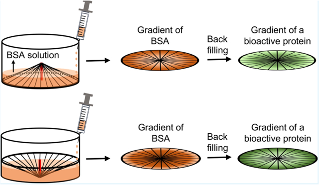
Scaffolds functionalized with circular gradients of active proteins are attractive for tissue regeneration because of their enhanced capability to accelerate cell migration and/or promote neurite extension in a radial fashion. Here, we report a general method for generating circular gradients of active proteins on scaffolds composed of radially aligned nanofibers. In a typical process, the scaffold, with its central portion raised using a copper wire to take a cone shape, was placed in a container (upright or up-side-down), followed by dropwise addition of bovine serum albumin (BSA) solution into the container. As such, a circular gradient of BSA was generated along each nanofiber. The bare regions uncovered by BSA were then filled with an active protein of interest. In demonstrating their potential applications, we used different model systems to examine the effects of two types of protein gradients. While the gradient of laminin and epidermal growth factor accelerated the migration of fibroblasts and keratinocytes, respectively, from the periphery toward the center of the scaffold, the gradient of nerve growth factor promoted the radial extension of neurites from the embryonic chick dorsal root ganglion. This method for generating circular gradients of active proteins can be readily extended to different types of scaffolds to suit wound closure and related applications that involve cell migration and/or neurite extension in a radial fashion.
Keywords: radially aligned nanofibers, active protein gradient, cell migration, neurite extension, wound dressing
Graphical Abstract
1. INTRODUCTION
In designing scaffolds for tissue regeneration, both topographical and biochemical cues should be incorporated to maximize the rates of cell migration and proliferation. In particular, the synergistic effect between topographical guidance and chemotaxing can contribute to the quick establishment of a microenvironment that simulates the structures and functions of the native extracellular matrix (ECM).1,2 To this end, electrospun nanofibers have been extensively explored as scaffolds for tissue regeneration owing to their capability to mimic the collagen nanofibers in ECM by offering topographic guidance.3–8 Electrospun nanofibers covered with linear gradients of active proteins have been demonstrated for promoting or regulating cell migration, proliferation, and differentiation.9–13 To this end, a variety of strategies have been developed for incorporating protein gradients into scaffolds based on electrospun nanofibers. Li et al. used an electrohydrodynamic jet printing technique to produce a linear gradient of protein droplets on electrospun fibers by adjusting the translation speed of the movable collector along the lateral directions.14 Similarly, a linear gradient of protein-encapsulated microparticles was generated across a substrate by spatially varying the deposition time during which the substrate was exposed to the electrosprayed microparticles.15 Another commonly used approach is based upon the strategy of varying the immersion time of a nanofiber scaffold in a solution along a particular direction. This approach has been successfully utilized to create linear gradients of proteins, mineral contents, and even cells on the scaffolds of electrospun nanofibers.11,16–18
Despite the successful development of nanofiber scaffolds covered with linear gradients of active proteins, we still lack a general method for generating circular gradients of active proteins. In a previous study, we demonstrated a facile method for fabricating radially aligned nanofibers using a collector consisting of a central point electrode and a peripheral ring electrode. It was shown that the dural fibroblasts cultured on the radially aligned nanofibers migrated toward the center of the scaffold at a higher speed than that on a counterpart consisting of random nanofibers.19 This class of scaffolds shows great potential as biomedical patches to accelerate the regeneration of dura mater. When integrated with circular gradients of active proteins, such scaffolds would be further empowered to accelerate cell migration from the periphery toward the center and thus speed up wound closure. For another application in the regeneration of an optic nerve, this type of scaffold coated with a circular gradient of an active protein would not only provide a topological structure to mimic the radial axon paths in the retina20 but also offer a biological cue to further enhance the guidance of the neurite extension along the radial directions. However, to our knowledge, there is only one report by Li et al. for generating a circular gradient of collagen-binding domain (CBD)-fused proteins on radially aligned polycaprolactone (PCL)/collagen fibers. The CBD-fused proteins specifically bound to collagen, and the protein gradient was produced because of the gradual decrease in the fiber density from the center to the periphery.10 Actually, the proteins were not deposited in a gradient along each individual nanofiber. In addition, it will not be easy to extend this method to nanofibers free of collagen and/or to proteins without CBD.
As reported in a recent study, a linear gradient of an active protein could be readily produced on a scaffold of uniaxially aligned nanofibers by back-filling the active protein onto the bare regions left behind by a graded mask of bovine serum albumin (BSA).21 Here, we further demonstrate that the capability of this strategy can be extended to generate a circular gradient of an active protein along radially aligned nanofibers. Specifically, a scaffold of radially aligned nanofibers is placed in a container, with the center of the scaffold being raised or depressed using a copper wire. A graded mask of BSA along the radial alignment is then produced by introducing a BSA solution dropwise. Afterward, an active protein is adsorbed onto the bare regions left behind by the BSA mask to generate a circular gradient of the active protein that runs countercurrent to BSA. As a major advantage, this simple and general method can be easily adapted for various types of active proteins and electrospun nanofibers. The use of BSA blocking also allows us to greatly reduce the usage of an expensive protein such as a growth factor in generating the desired gradient. As a proof-of-concept demonstration in terms of potential applications, we investigate the effects of a laminin gradient on fibroblast migration and an epidermal growth factor (EGF) gradient on keratinocyte migration from the periphery toward the center for the purpose of wound closure. Additionally, we examine the effect of a nerve growth factor (NGF) gradient increasing from the center to the periphery on the neurite extension for potential use in the regeneration of retinal ganglion cell axons in the optic nerve.
2. EXPERIMENTAL METHODS
2.1. Fabrication and Characterization of Radially Aligned PCL Nanofibers.
We fabricated the radially aligned nanofibers using an electrospinning setup similar to what was reported in our previous study.19 PCL (Mw ≈ 80 000 g/mol, Sigma-Aldrich, St. Louis, MO) was dissolved in 2,2,2-trifluoroethanol at a concentration of 10 wt %. The PCL solution was pumped out at a rate of 1.0 mL/h through a blunt needle (22-gauge). A high voltage (dc) of 15 kV was applied between the needle and a grounded collector separated by 13 cm. A metallic ring with a sharp needle in the center was used as the collector to obtain radially aligned nanofibers. After 10 min, the electrospinning process was terminated. The sample was coated with Au/Pd using a Hummer 6 sputter (Anatech, Union City, CA) and then imaged using a Hitachi 8230 cold-field emission scanning electron microscope (Tokyo, Japan). The average diameter of the nanofibers was measured using ImageJ software from 100 nanofibers in the scanning electron microscopy (SEM) images.
2.2. Generation and Characterization of a Circular Gradient of Active Protein on Radially Aligned PCL Nanofibers.
A scaffold of radially aligned nanofibers was first treated with oxygen plasma for 2 min in a plasma cleaner (Plasma Etch, Carson City, NV) and sterilized under UV for 1 h. The scaffold was placed in the well of a 24-well plate, with the center of the scaffold being raised by 4 mm using a copper wire. Then, 0.1% BSA solution was pumped into the well at a flow rate of 1.0 mL/h to create a graded mask of BSA. After the solution level had reached the top point, in about 35 min, the sample was removed from the BSA solution. The copper wire was dismissed, and the scaffold masked by a gradient of BSA was immediately rinsed three times with phosphate-buffered solution (PBS). Afterward, the scaffold was placed in the well of a 24-well plate and immersed in 100 μL of laminin solution (50 μg/mL) at 4 °C overnight, followed by rising three times with PBS. In this way, laminin was adsorbed onto the bare regions left behind by the BSA mask to generate a gradient increasing from the periphery to the center. The EGF gradient was generated using the same method as described above by immersing the BSA-masked scaffold in 100 μL of 10 μg/mL EGF solution at 4 °C overnight. To generate an opposite gradient of NGF (rather than laminin or EGF) increasing from the center to the periphery, the same method of BSA blocking was used except that the center-raised scaffold was placed in the well up-side-down. Subsequently, the scaffold masked by a gradient of BSA was treated by immersing in 100 μL of 10 μg/mL NGF solution at 4 °C overnight, followed by rinsing with PBS. For comparison, a uniform coating of BSA was generated by immersing the nanofiber scaffold in the BSA solution and incubating for 35 min, followed by rinsing with PBS. The BSA-blocked scaffolds were then functionalized with laminin, EGF, and NGF, using the method described above. The radially aligned nanofibers treated by immersing in PBS served as a control.
We started with fluorescein isothiocyanate-labeled BSA (FITC-BSA) to characterize the resultant protein gradients after filling the uncovered regions left behind by BSA blocking. In this case, 100 μL of 0.1% FITC-BSA in PBS solution was pipetted onto the scaffolds masked by a graded or uniform layer of BSA. The samples were incubated in the dark for 2 h at room temperature. Subsequently, the nanofiber scaffolds were washed three times with 0.1% Tween 20 solution, rinsed three times with PBS, and observed under a Leica DMI6000 B inverted microscope (Buffalo Grove, IL). On the circular nanofiber scaffold coated with graded or uniform FITC-BSA, we chose five different positions with the same incremental distance along the radial axis from the center to the periphery. At each position, a region with the same area was imaged under the fluorescence microscope. The average fluorescence intensity at each position was calculated from four samples using ImageJ software and plotted.
2.3. Migration of NIH-3T3 Fibroblasts.
We first assessed the viabilities of cells on the different types of nanofiber scaffolds. The Cell Counting Kit-8 (CCK-8; Sigma-Aldrich) assay was performed after seeding NIH-3T3 fibroblasts on the different scaffolds for 1, 3, 5, and 7 days. Cells cultured on tissue culture plates (TCPs) and laminin-coated TCP served as the control groups. At each time point, the cells were washed with PBS, and then the fresh culture medium with 10% CCK-8 reagent was added into each well. After 4 h, the well plate was shaken for 15 min, and the absorbance of the supernatant at 450 nm was measured using a microplate reader.
We then investigated the combined effect of the nanofiber alignment and laminin gradient on the migration of NIH-3T3 fibroblasts. The nanofiber scaffolds coated with a graded and uniform layer of laminin, as well as scaffolds made of bare nanofibers, were separately transferred into the wells of a 24-well plate after lifting off the scaffolds from the edge of the metal rings. The cells cultured on laminin-coated TCP served as control. In each well, a polydimethylsiloxane (PDMS) cylinder of 6 mm in diameter was placed in the center. The NIH-3T3 fibroblasts were dissociated in Dulbecco’s modified eagle medium supplemented with 10% fetal bovine serum (FBS) and 1% antibiotic-antimycotic (ABAM), and then seeded at a concentration of 1 × 10⁵ cells/mL onto the surrounding areas left by the PDMS cylinders. After cell adhesion for 4 h, the cylinders were removed to allow the cells to migrate inward.
After incubation for 3 days, the NIH-3T3 fibroblasts on different samples were stained with Alexa Fluor 555 phalloidin and 4′,6-diamidino-2-phenylindole (DAPI). Briefly, the cells were fixed in 3% glutaraldehyde solution at room temperature for 10 min and permeabilized with 0.1% Triton X-100 for 5 min. Staining solution of Alexa Fluor 555 phalloidin was prepared by diluting 5 μL of methanolic stock solution in 200 μL of PBS for each sample. Then, 1% BSA was added into the staining solution to reduce nonspecific background staining. The samples were incubated in the staining solution for 20 min at room temperature. Afterward, the nuclei of the cells were stained with DAPI for 5 min. Between each procedure, the samples were washed three times with PBS. After staining, the samples were imaged using the Leica DMI6000 B inverted microscope.
Micrographs were taken at a low magnification to analyze the distribution and migration of cells on different samples. High-magnification micrographs were also acquired to examine the morphology and alignment of the cells. The migration zone on each sample was divided into three regions with the same incremental distance along the radial axis from the center to the periphery. The number of cells in each migration region was measured from the fluorescence micrographs of DAPI staining using ImageJ software. The migration index (MI) of each sample was calculated to evaluate the migration ability of the cells. The ratio of the sum of the numbers of practically migrated cells multiplied by migrated distances to the theoretical value, termed as MI, was calculated using the following equation
where N1, N2, and N3 are the numbers of migrated cells in three consecutive regions. L1, L2, and L3 are the correspondingly migrated distances from the originally seeded site to different migration regions.
2.4. Migration of Keratinocytes.
To investigate the combined effect of the nanofiber alignment and EGF gradient on the migration of keratinocytes, we separately transferred the nanofiber scaffolds coated with a graded and uniform layer of EGF, masked by a gradient of BSA, and made of bare nanofibers, into the wells of a 24-well plate. We then followed the same method as described in section 2.3 to investigate the migration of keratinocytes on the different scaffolds, except that the keratinocytes were dissociated and cultured in medium 154 supplemented with 1% human keratinocyte growth supplement and 1% ABAM. After incubation for 3 days, the keratinocytes were stained with Alexa Fluor 555 phalloidin and DAPI. The number of cells in each migration region was measured, and the MI of cells on each type of scaffold was calculated.
2.5. DRG Neurites Extension.
We further investigated the combined effect of the nanofiber alignment and NGF gradient on the extension of neurites from the embryonic chick dorsal root ganglion (DRG). All DRG cells were isolated from the thoracic region of the spinal column in embryonic chick via sterile microdissection.22 Embryonic day 8 (E8, stage HH35–36) chicks were removed from the white leghorn egg and decapitated. DRG cells were dissected from the thoracic region and collected in Hanks’ balanced salt solution. Then, the DRG cells were seeded onto the samples (1 DRG per sample) and cultured in a modified neurobasal medium supplemented with 10% FBS, 1% N-2 supplement, 1% ABAM, and 50 ng/mL NGF. After incubation for 6 days, the samples were fixed in 3% glutaraldehyde for 10 min, permeabilized with 0.1% Triton X-100 for 5 min, and blocked with 3% BSA/PBS solution for 1 h. Then, the samples were incubated with Tuj1 primary antibody at 4 °C overnight, followed by staining using Alexa Fluor 488 secondary antibody for 1 h. Between steps, the samples were rinsed three times with PBS solution. Fluorescence micrographs were captured using the Leica DMI6000 B inverted microscope. The average lengths of the extended neurites on either side of the DRG bodies were measured from the fluorescence micrographs using ImageJ software. Six DRG cells on each type of sample were used to calculate the neurite length.
2.6. Statistical Analysis.
Comparison between groups was performed using one-way ANOVA, followed by Student’s t-tests for all pairwise comparisons. All the values were averaged at least in triplicate and presented in the form of mean ± standard deviation.
3. RESULTS AND DISCUSSION
3.1. Generation of a Circular Gradient of Active Protein on Radially Aligned PCL Nanofibers.
We first fabricated radially aligned PCL nanofibers by electrospinning, with the use of a collector comprising a metallic ring (the ring electrode) and a metallic needle (the point electrode).19 Figure 1A shows a schematic of the setup. The electrospun nanofibers were deposited across the gap between the needle and the ring in a radial alignment (Figure 1B). Figure 1C shows a photograph of the as-obtained nanofiber scaffold whereas Figure 1D presents an optical micrograph captured from the central portion of the scaffold. As confirmed by the SEM images in Figure S1, the deposited nanofibers were radially aligned from the center toward the periphery of the scaffold, with an average fiber diameter of 428 ± 34 nm.
Figure 1.
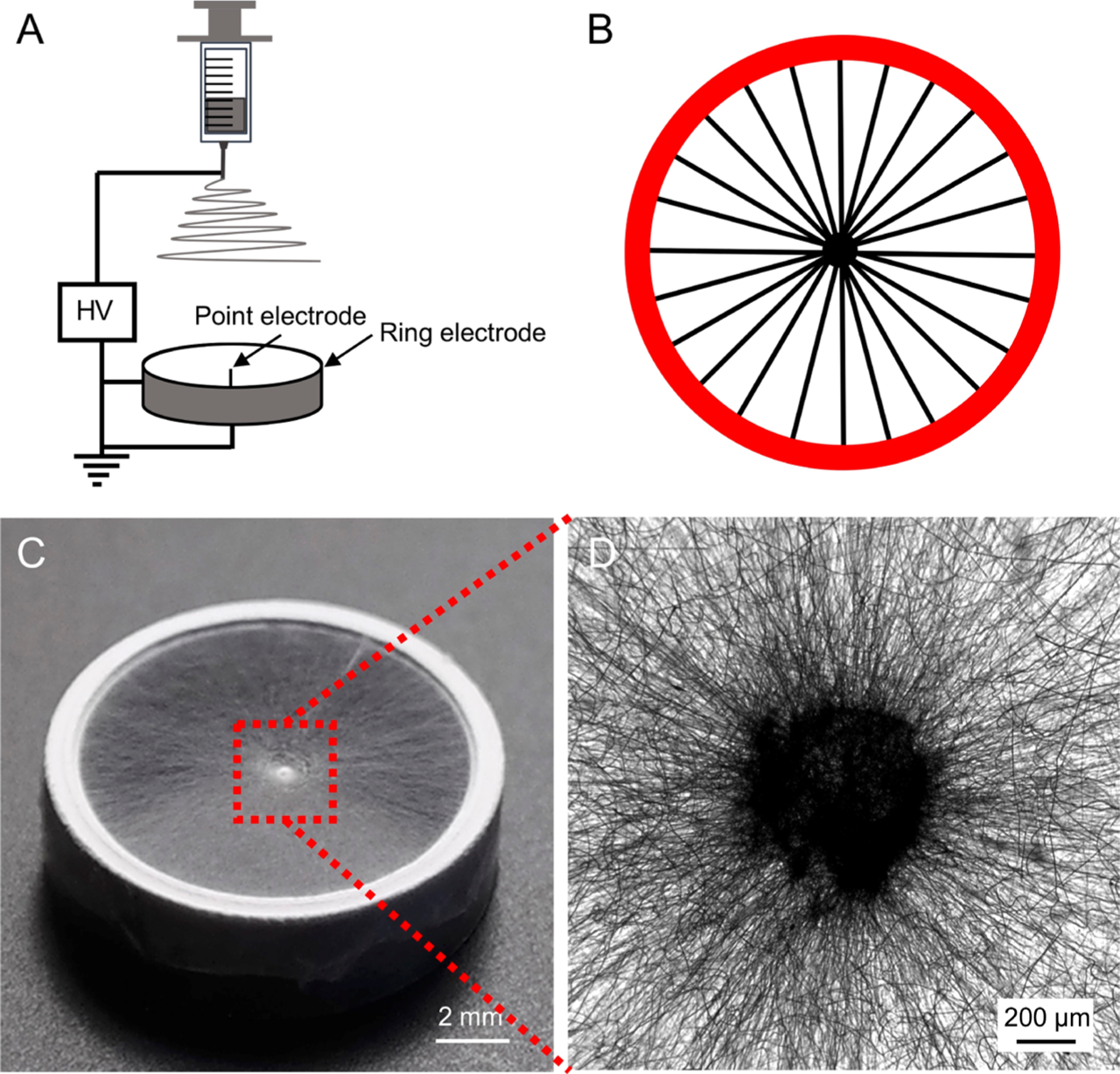
(A) Schematic of the electrospinning setup used for generating a scaffold consisted of radially aligned PCL nanofibers. (B) Schematic showing the nanofibers aligned across the point and ring electrodes. (C) Photograph showing a typical sample of radially aligned PCL nanofibers. (D) Optical micrograph captured from the central portion of the scaffold.
We then generated a circular gradient of an active protein on the radially aligned nanofibers. As illustrated in Figure 2, the nanofiber scaffold was placed in the well of a 24-well plate after the central portion had been raised with a copper wire. We then added a BSA solution dropwise into the well at a fixed injection rate to create a gradient of BSA. Afterward, the copper wire was removed and the regions on the nanofibers unblocked by BSA were filled with an active protein to generate a gradient of the protein that ran countercurrent to BSA. In this way, we obtained a circular gradient of an active protein, whose coverage density increased from the periphery to the center. Similarly, a circular gradient of an active protein that increased from the center to the periphery was also created using the same strategy except that the center-raised scaffold was placed in the well up-side-down. For comparison, a uniform coating of BSA was generated by immersing the nanofiber scaffold in the BSA solution, followed by rinsing with PBS. The BSA-masked scaffold was then functionalized with the active protein. A scaffold of bare nanofibers was also treated by directly immersing in PBS and used as a control. Figure S2 shows a schematic of the scaffold coated with a graded or uniform layer of BSA and the corresponding scaffold with a graded or uniform coating of the active protein.
Figure 2.
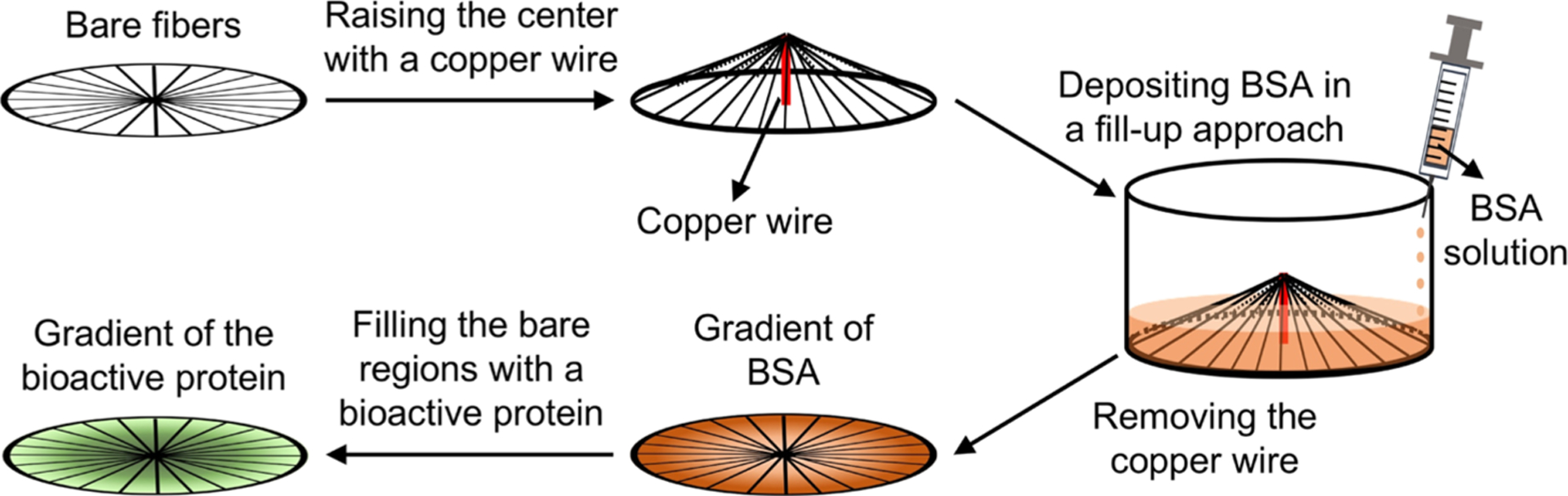
Schematic for generating a circular gradient of an active protein along radially aligned nanofibers. Plasma-treated nanofiber scaffold, whose center is raised by 4 mm with a copper wire, is placed in the well of a 24-well plate. Gradient of BSA is then created by pumping 0.1% BSA solution into the well at a rate of 1 mL/h. Bare regions left by BSA are then filled with an active protein to generate a gradient that runs countercurrent to the BSA gradient. In this way, radial gradient increasing from the periphery to the center is generated. Similarly, opposite gradient increasing from the center toward the periphery can be produced using the same approach except that the center-raised scaffold is placed in the well up-side-down.
To visualize the gradients, we used FITC-BSA as a model protein and performed the above procedures to obtain nanofiber scaffolds covered with a graded or uniform coating of FITC-BSA. Figure 3 shows the relative fluorescence intensities at different locations on the nanofiber scaffolds, as marked in the illustration, and the corresponding fluorescence images are shown in Figure S3. Along the radial direction, a continuous change in the fluorescence intensity was clearly observed for the nanofiber scaffold coated with FITC-BSA in a gradient, whereas no obvious change was found for the nanofiber scaffold uniformly coated with FITC-BSA. For the scaffold with a gradient of FITC-BSA that increased from the center to the periphery, the fluorescence intensity at the periphery was nearly four times stronger than that at the center. Similarly, the fluorescence intensity of the nanofiber scaffold with an opposite gradient of FITC-BSA showed a three-fold decrease from the center to the periphery. These results confirmed that a circular gradient of the active protein was successfully generated along the radially aligned nanofibers. We further evaluated the stability of the as-obtained gradient of FITC-BSA on the nanofiber scaffold. No obvious change to the gradient of the fluorescence intensity was observed even after the scaffold had been immersed in PBS for one week. It is well-documented that proteins tend to spread across a surface during adsorption and are only irreversibly bound as a monolayer.23,24 The proteins reversibly bound to the surface were washed away when the nanofiber scaffold was rinsed with a buffer solution at each step. Taken together, it can be concluded that the resulting gradient was composed of irreversibly bound proteins and that is why the gradient showed good stability.
Figure 3.
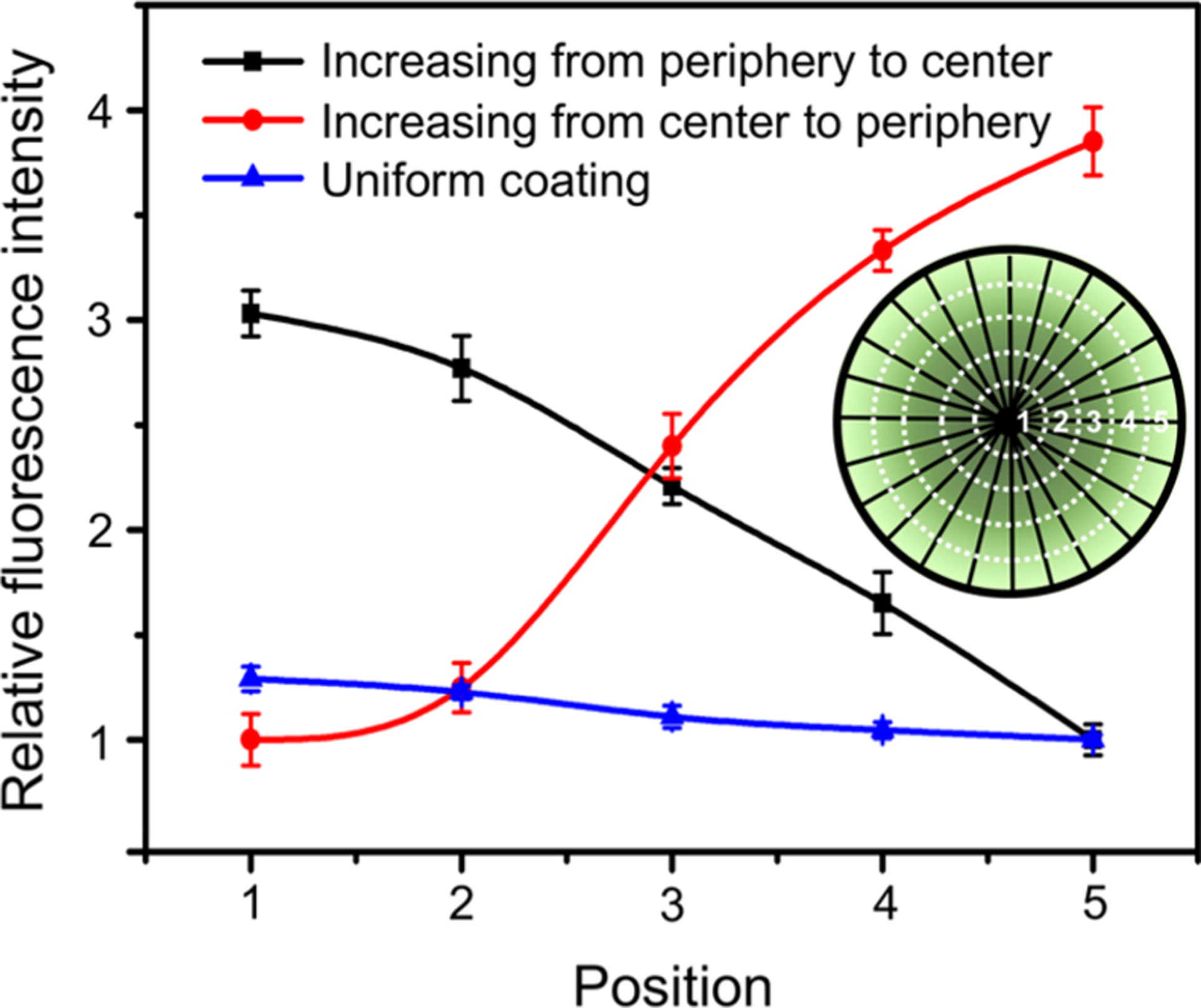
Relative fluorescence intensity showing a graded or uniform coating of FITC-BSA along the radially aligned nanofibers generated through BSA blocking. The inset shows a schematic of the corresponding positions along the radial direction.
3.2. Migration of NIH-3T3 Fibroblasts and Keratinocytes.
Scaffolds made of radially aligned nanofibers could promote wound closure by inducing cell migration along the radial direction.19 Here, we demonstrate that the contact guidance for cell migration can be further enhanced by combining a biological cue with a topographic cue presented by the nanofibers. Laminin is a major component of the basal lamina and is known to play critical roles in cell migration, proliferation, and differentiation.25 To study the combined effect of the radial alignment and laminin gradient on the migration and proliferation of NIH-3T3 fibroblasts, we fabricated and compared nanofiber scaffolds coated with graded laminin increasing from the periphery to the center, covered with a uniform coating of laminin, and made of bare nanofibers. We first investigated cell viabilities on the three different types of scaffolds, with TCP and laminin-coated TCP served as two control groups. As shown in Figure 4A, cell proliferation on scaffolds covered with a graded or uniform coating of laminin was better relative to the scaffold composed of bare nanofibers, regardless of the culturing time. The cell viability on the scaffolds coated with graded laminin was significantly greater (at P < 0.05 level) than that on TCP when the cells proliferated to 5 and 7 days (Figure 4B). These findings indicate that coating nanofiber scaffolds with laminin could indeed improve both the proliferation and viability of cells, mainly because of the bioactivity of laminin and the improved surface wettability.26
Figure 4.
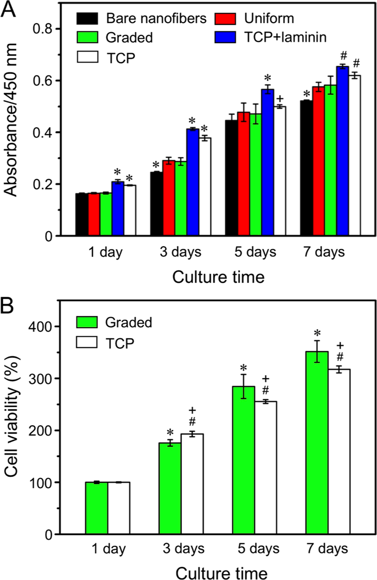
(A) Proliferation of NIH-3T3 fibroblasts on the different types of nanofiber scaffolds tested by CCK-8 assay. *P < 0.05 relative to the other groups at the same culture time; #P < 0.05 relative to the scaffolds coated with graded and uniform laminin, and bare nanofibers; and +P < 0.05 as compared with that on bare nanofibers. (B) Viabilities of cells cultured on the scaffolds covered with a gradient of laminin and on TCP at different incubation times. *P < 0.05 as compared with that on scaffolds coated with graded laminin at 1 day; #P < 0.05 as compared with that on TCP at 1 day; and +P < 0.05 as compared with that on scaffolds coated with graded laminin at the same time point.
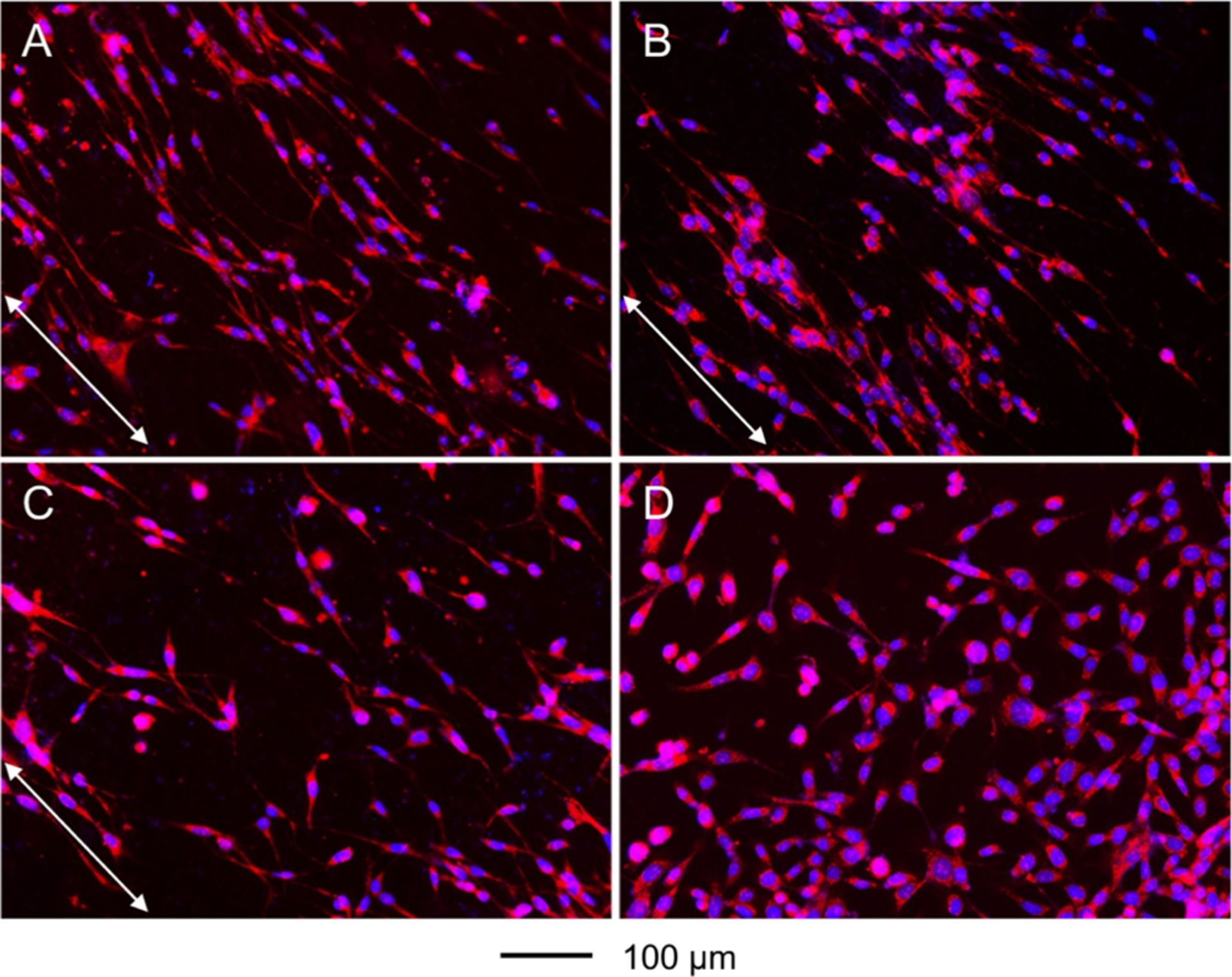
The migration of NIH-3T3 fibroblasts on the different types of nanofiber scaffolds was investigated using a specific cell culture system (Figure S4), with a laminin-coated TCP serving as a control. Briefly, a PDMS cylinder was placed in the center of the nanofiber scaffold as a physical block to generate a migration region with a diameter of 6 mm. Cells were seeded around the periphery of the PDMS cylinder. The cylinder was removed 4 h after seeding to allow the cells to migrate inward. After 3 days, we stained the cells with DAPI and Alexa Fluor 555 phalloidin to reveal the positions of the cells on the various substrates. In general, the actin cytoskeleton stained by Alexa Fluor 555 phalloidin should be organized in the same direction as the cell movement.27 Figure 5 shows the fluorescence micrographs of the cells on different types of nanofiber scaffolds and laminin-coated TCP. On the scaffolds coated with graded laminin, the cells almost covered the entire area of the migration zone, and a large number of cells were observed in the center. The contact guidance provided by the underneath nanofibers and the circular gradient of laminin synergistically promoted cell migration toward the increased content of laminin along the radial alignment. By contrast, fewer cells were found in the migration zones of scaffolds covered with a uniform coating of laminin, scaffolds composed of bare nanofibers, and laminin-coated TCP. In particular, very few cells appeared in the central areas of scaffolds made of bare nanofibers and laminin-coated TCP. The cells tended to migrate along the radially aligned nanofibers, whereas the cells took a random track on TCP. It has been reported that the cytoskeleton, composed of actin microfilaments, microtubules, and intermediate filaments, plays a critical role in cell migration.28 As shown in Figure 6A–C, the cytoskeleton took an elongated morphology and large extension on the radially aligned nanofibers. By contrast, the cells took a random arrangement and less extension when cultured on laminin-coated TCP (Figure 6D). Recent studies have demonstrated that cell migration relies strongly on the ECM, and the regulation of cell motility depends on the dimensionality of features, as well as physical and biochemical environments.29 Cells can sense the guide taxis provided by the radial alignment of nanofibers and the circular gradient of laminin, taking an elongated orientation and migrating toward the central region with the highest laminin content.
Figure 5.

Fluorescence micrographs showing the migration of NIH-3T3 fibroblasts on radially aligned nanofibers covered with (A) a graded and (B) uniform coating of laminin, respectively, (C) bare radially aligned nanofibers, and (D) laminin-coated TCP after culture for 3 days. The cells nuclei were stained with DAPI (blue) and the actin cytoskeleton was stained with Alexa Fluor 555 phalloidin (red). The dashed lines indicate the border of cell seeding.
Figure 6.
Fluorescence micrographs showing the morphology and alignment of NIH-3T3 fibroblasts cultured on radially aligned nanofibers covered with (A) a graded and (B) uniform coating of laminin, respectively, (C) bare radially aligned nanofibers, and (D) laminin-coated TCP. The images were captured from the migration zones. The cells nuclei were stained with DAPI (blue) and the actin cytoskeleton was stained with Alexa Fluor 555 phalloidin (red). The arrows indicate the direction of the nanofiber alignment.
From the fluorescence micrographs of DAPI nuclear staining (Figure S5), we separately measured the average cell number in three consecutive regions in the migration zone along the direction of the radial alignment, as illustrated in Figure S6. Figure 7A shows the average number of cells in each region of the migration zone on different types of nanofiber scaffolds and laminin-coated TCP. The number of cells migrated to the central area (region 1) of the scaffold coated with a circular gradient of laminin was increased by 1.24-, 1.99-, and 6.24-fold, respectively, relative to those on the scaffolds covered with a uniform coating of laminin, composed of bare nanofibers, and laminin-coated TCP. We further calculated the MI in relation to the ability of cell migration on the different types of substrates. Figure S6 illustrates the method used for calculating the MI. The MI is defined as the ratio of the sum of the numbers of practically migrated cells multiplied by migrated distances to the theoretical value. From the calculation formula, cells possess greater migration ability when their migration indices approach unity. Figure 7B shows the migration indices for cells cultured on different types of nanofiber scaffolds and laminin-coated TCP. For the cells cultured on the nanofiber scaffolds covered with a gradient of laminin, they possessed the greatest MI of 0.594 ± 0.004. This value was significantly different (at P < 0.01 level) when compared with those of cells cultured on scaffolds covered with a uniform coating of laminin (0.559 ± 0.005), scaffolds consisted of bare nanofibers (0.531 ± 0.014), and laminin-coated TCP (0.471 ± 0.002). We also demonstrated that the graded coating of BSA on the nanofiber scaffolds had no impact on cell migration when compared with that on the scaffolds made of bare nanofiber. The number of cells migrated to the central area and the MI of cells on the scaffolds coated with graded laminin were significantly larger (at P < 0.01 level) than that cultured on scaffolds masked by graded BSA, as shown in Figure S7. These results confirm that the cells possess the greatest migration ability when cultured on the scaffolds composed of radially aligned nanofibers and coated with a circular gradient of laminin. Compared with the random pattern and slow migration on TCP substrates, the contact guidance provided by the radially aligned nanofibers induced elongation, orientation, and quick migration of cells along the radial alignment. Furthermore, the laminin coating on the nanofiber scaffolds enhanced the cell viability and proliferation, promoting additional cell migration compared with scaffolds consisted of bare nanofibers. Cells tended to migrate faster on the scaffolds coated with graded laminin than those with a uniform coating of laminin, mainly because of the guide taxis provided by the protein gradient, which could promote cells to migrate toward a higher protein content. The results indicate that the circular gradient of laminin along with the radial nanofiber alignment has a synergetic effect in promoting cell migration away from the cell source and toward the region with the greatest laminin content.
Figure 7.
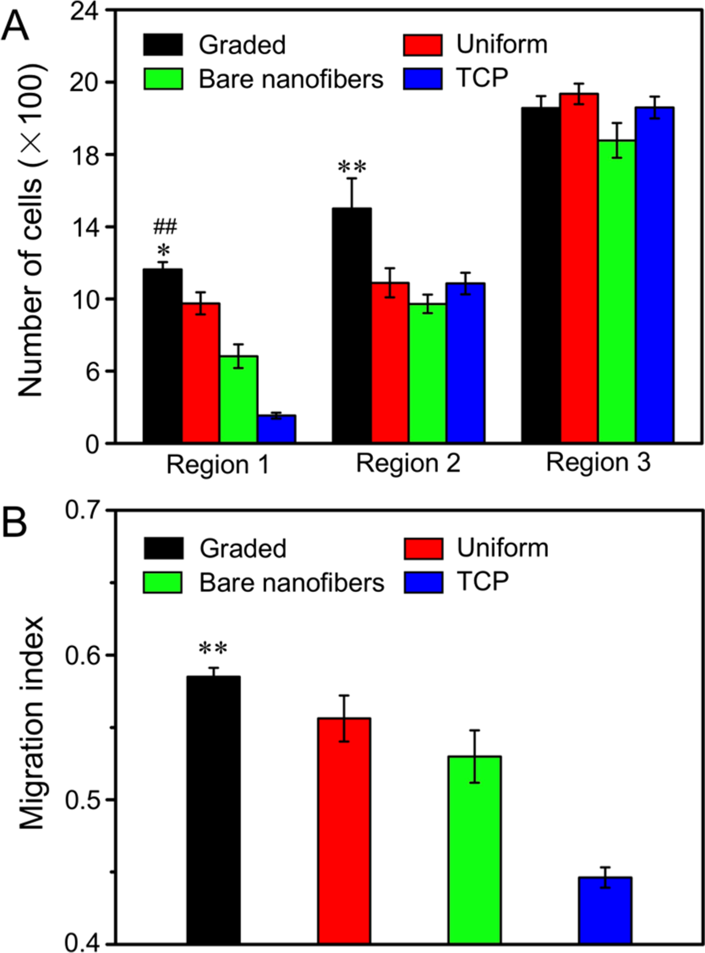
(A) Number of cells in different regions of the migration zone on radially aligned nanofibers covered with a graded or uniform coating of laminin, bare nanofibers, and laminin-coated TCP after 3 days of culture. *P < 0.05 as compared with that on scaffolds covered with a uniform coating of laminin; ##P < 0.01 relative to the scaffolds made of bare nanofibers and laminin-coated TCP; and **P < 0.01 relative to the scaffolds covered with a uniform coating of laminin, scaffolds made of bare nanofibers, and laminin-coated TCP. (B) MI calculated from the numbers of migrated cells in different regions. **P < 0.01 when compared with those of cells cultured on scaffolds covered with a uniform coating of laminin, scaffolds made of bare nanofibers, and laminin-coated TCP.
To evaluate the potential of the protein gradient in wound closure, we also examine the effect of a circular gradient of EGF on the migration of keratinocytes (Figure 8). We found that the number of keratinocytes migrated to the central area (region 1) on the scaffolds coated with graded EGF was increased by 1.50-, 3.52-, and 3.42-fold, respectively, relative to those on the scaffolds covered by a uniform coating of EGF, masked by graded BSA, and composed of bare nanofibers. The number of cells migrated to the middle area (region 2) on the scaffolds coated with graded EGF was increased by 1.65-, 3.84-, and 3.59-fold, respectively, relative to those on the scaffolds covered with a uniform coating of EGF, masked by graded BSA, and composed of bare nanofibers. For the keratinocytes cultured on the scaffolds covered with a gradient of EGF, they possessed the greatest MI of 0.626 ± 0.008. This value was significantly higher than those obtained by culturing the cells on the scaffolds covered with a uniform coating of EGF (0.598 ± 0.014) at P < 0.05 level, masked by graded BSA (0.509 ± 0.020) and consisted of bare nanofibers (0.512 ± 0.006) at P < 0.01 level. These results indicate that a circular gradient of EGF on radially aligned nanofibers can promote keratinocytes migration from the periphery to the center. Taken together, this class of scaffolds coated with a gradient of the active protein shows a great promise for wound closure.
Figure 8.
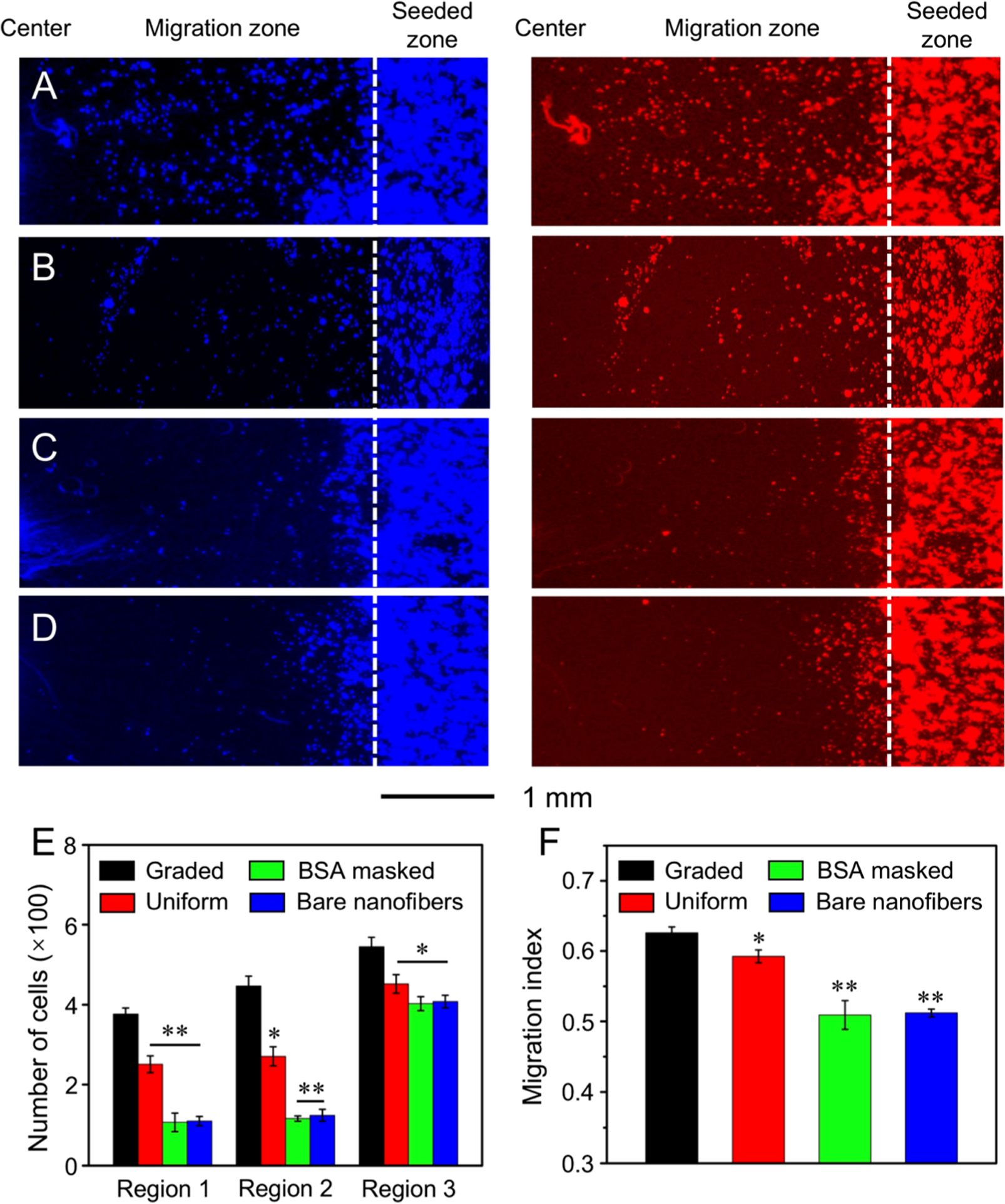
Fluorescence micrographs showing the migration of keratinocytes on radially aligned nanofibers covered with (A) a graded and (B) uniform coating of EGF, respectively, (C) radially aligned nanofibers masked by a gradient of BSA, and (D) bare radially aligned nanofibers after culture for 3 days. The cells nuclei were stained with DAPI (blue) and the actin cytoskeleton was stained with Alexa Fluor 555 phalloidin (red). The dashed lines indicate the border of cell seeding. (E) The number of cells in different regions of the migration zone on different scaffolds after 3 days of culture. (F) MI calculated from the numbers of migrated cells in different regions. *P < 0.05 and **P < 0.01 when compared with that of cells cultured on scaffolds coated with graded EGF.
3.3. DRG Neurites Extension.
Scaffolds consisting of radially aligned nanofibers provide a potential alternative to direct the growth of retinal ganglion cell axons radially, in an effort to mimic the radial axon paths in the retina.20 The neurotrophic effect, when combined with the contact guidance of aligned nanofibers, could be used to maximize neurite extension.30 Herein, we fabricated radially aligned nanofiber scaffolds coated with an increasing NGF gradient from the center to the periphery to investigate neurite extension from DRG. The scaffolds covered with a uniform coating of NGF and scaffolds consisted of bare nanofibers served as controls.
Figure 9A–C shows fluorescence micrographs of the typical neurite fields extending from DRG seeded on the different types of nanofiber scaffolds. Because of the contact guidance provided by the underneath nanofibers in all cases, the neurites extruding from DRG bodies followed the radial alignment of nanofibers, as indicated by white arrows. By contrast, the neurites on TCP extended with a random and isotropic pattern around the DRG body.30 The average neurite lengths outgrowing from the DRG bodies toward the center or the periphery are displayed in Figure 9D. Because of the guidance provided by the increasing NGF gradient from the center to the periphery, the average neurite length toward the periphery was significantly enhanced to 1.34 ± 0.19 mm by additional 44% as compared with 0.93 ± 0.23 mm toward the center on the scaffolds coated with a circular gradient of NGF. When NGF was uniformly coated on the scaffolds, the average neurite length toward the center and the periphery was 0.79 ± 0.18 mm and 0.73 ± 0.18 mm, respectively. No significant difference was found between either sides of the DRG cell mass. In the presence of NGF, the DRG neurites extended longer on the nanofiber scaffolds covered with a graded and uniform coating of NGF than those on bare nanofibers (0.27 ± 0.06 mm toward the center and 0.24 ± 0.04 mm toward the periphery), regardless of the extending directions. It has been reported that the growth cones of DRG neurites could recognize the growth factor, expand their membranes, and then stretch for the next bound factor when DRG cells were cultured on nanofibers coated with NGF.31 The NGF enhanced the attachment of growth cones on nanofibers and provided an anchor to further expand the growth cones for neurite extension.21 By increasing the NGF content along the radially aligned nanofibers, the growth cones of neurites could sense more growth factors within their reach and further expand their membranes along the direction of the NGF gradient.21,32 As a result, the neurites extending toward the increased content in NGF were significantly longer by 1.44-fold than neurites extending against the gradient on the radially aligned nanofibers.
Figure 9.
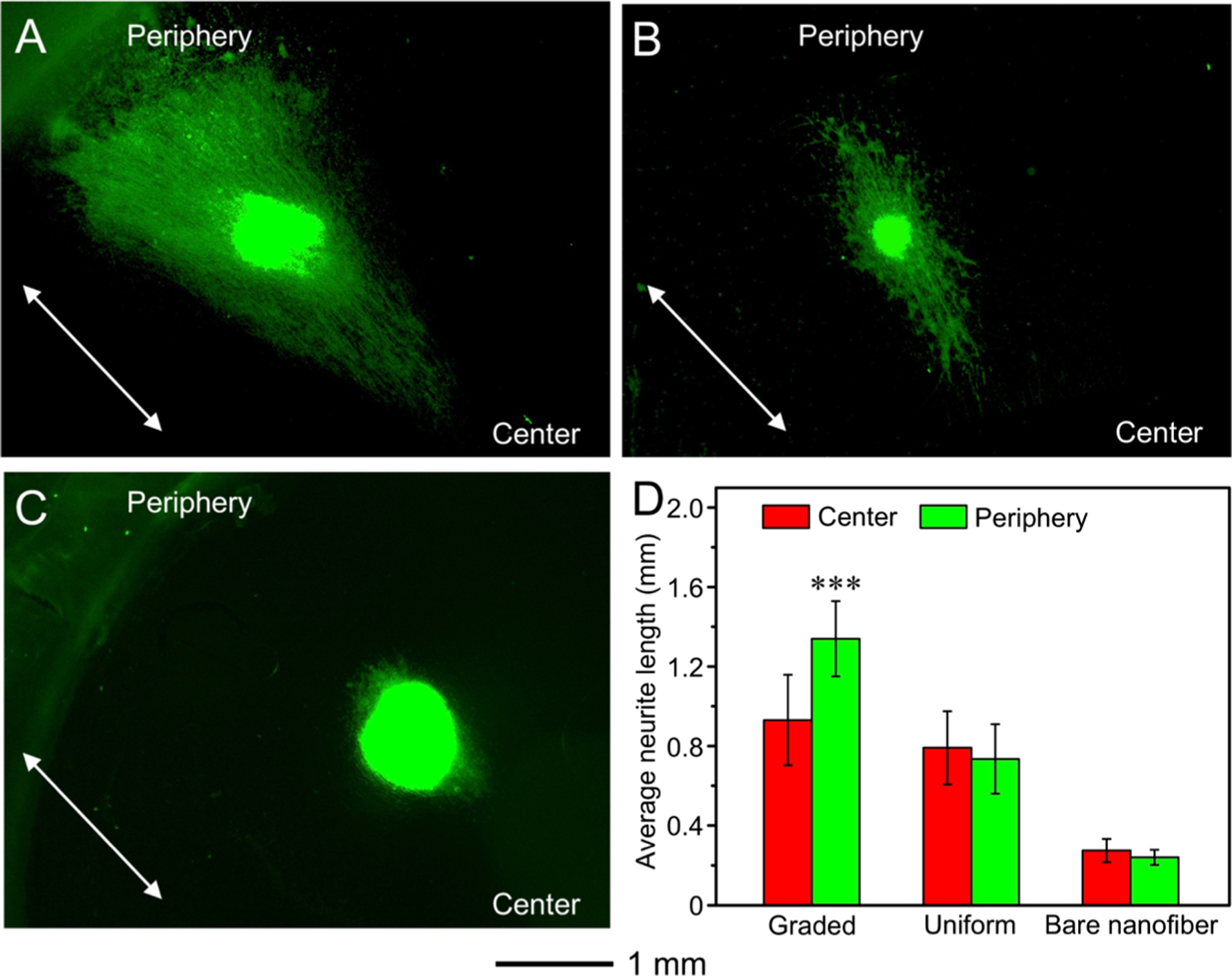
Fluorescence micrographs of the typical neurite fields extending from DRG bodies when cultured on radially aligned nanofibers coated with (A) a graded and (B) uniform layer of NGF, respectively, and (C) bare radially aligned nanofibers for 6 days. The neurites were stained with Tuj1 marker (green). The arrows indicate the direction of the nanofiber alignment. (D) Analyses of the average lengths of the neurites outgrowing from the chick DRG bodies cultured on different nanofiber scaffolds. ***P < 0.001 as compared with that extending from DRG bodies toward the center. No significant difference was found between either side of the DRG bodies on scaffolds covered with a uniform coating of NGF and made of bare nanofibers.
4. CONCLUSION
In summary, we have demonstrated a simple and general strategy for generating circular gradients of active proteins on radially aligned nanofibers first by creating a graded mask of BSA. By constantly increasing the volume of BSA solution introduced into a container with a center-raised nanofiber scaffold placed in the upright or up-side-down configuration, a gradient of BSA can be generated along the radially aligned nanofibers. Then, the bare regions left behind by the BSA are filled with an active protein of interest to generate a circular gradient of the active protein that runs countercurrent to BSA. This class of scaffolds is able to present both a topographic cue in the radial alignment and a biochemical cue in the protein gradient toward the center or the periphery, which can be readily adapted for various types of active proteins and polymer scaffolds. As a demonstration for the potential applications in tissue engineering, a circular gradient of laminin, EGF, or NGF was generated on radially aligned PCL nanofibers along the nanofiber orientation. We showed that the migration of fibroblasts or keratinocytes toward the center of the nanofiber scaffold could be accelerated with the presence of a laminin or EGF gradient along the radial alignment. For the radially aligned nanofibers coated with a gradient of NGF, DRG neurites extended along the radial alignment of nanofibers, and the neurites extending toward the increase in NGF content were significantly longer by 1.44 fold than those extending in the opposite direction. Taken together, these studies provide valuable information for designing biochemically graded scaffolds integrated with a radially aligned topographical cue for potential use in wound closure and related applications requiring cell migration and/or neurite extension in a radial pattern.
Supplementary Material
ACKNOWLEDGMENTS
This work was supported in part by a grant from the NIH (R01 EB020050) and startup funds from the Georgia Institute of Technology. As a jointly supervised PhD candidate from Donghua University, T.W. was also partially supported by a fellowship from the China Scholarship Council.
Footnotes
Supporting Information
The Supporting Information is available free of charge on the ACS Publications website at DOI: 10.1021/acsami.8b00129.
SEM images of the radially aligned nanofibers; schematic illustration of the gradients of active proteins after BSA blocking; fluorescence images showing a gradient or uniform coating of FITC-BSA; schematic illustration of the cell culture system; representative DAPI immunofluorescence micrographs used for measuring cell numbers in the migration zones; schematic showing how to calculate MI based on the fluorescence micrographs of cell migration; and immunofluorescence micrographs showing fibroblast migration on the scaffolds masked with a gradient of BSA (PDF)
The authors declare no competing financial interest.
REFERENCES
- (1).Braghirolli DI; Steffens D; Pranke P Electrospinning for Regenerative Medicine: A Review of the Main Topics. Drug Discovery Today 2014, 19, 743–753. [DOI] [PubMed] [Google Scholar]
- (2).Kim S-E; Harker EC; De Leon AC; Advincula RC; Pokorski JK Coextruded, Aligned, and Gradient-Modified Poly(ε-caprolactone) Fibers as Platforms for Neural Growth. Biomacromolecules 2015, 16, 860–867. [DOI] [PMC free article] [PubMed] [Google Scholar]
- (3).Liu W; Thomopoulos S; Xia Y Electrospun Nanofibers for Regenerative Medicine. Adv. Healthcare Mater 2012, 1, 10–25. [DOI] [PMC free article] [PubMed] [Google Scholar]
- (4).He J-X; Zhou Y-M; Wu Y-C; Liu R-T Nanofiber Coated Hybrid Yarn Fabricated by Novel Electrospinning-Airflow Twisting Method. Surf. Coat. Technol 2014, 258, 398–404. [Google Scholar]
- (5).Joseph J; Nair SV; Menon D Integrating Substrateless Electrospinning with Textile Technology for Creating Biodegradable Three-Dimensional Structures. Nano Lett. 2015, 15, 5420–5426. [DOI] [PubMed] [Google Scholar]
- (6).Li H; Xu Y; Xu H; Chang J Electrospun Membranes: Control of the Structure and Structure Related Applications in Tissue Regeneration and Drug Delivery. J. Mater. Chem. B 2014, 2, 5492–5510. [DOI] [PubMed] [Google Scholar]
- (7).Lu P; Xia Y Maneuvering the Internal Porosity and Surface Morphology of Electrospun Polystyrene Yarns by Controlling the Solvent and Relative Humidity. Langmuir 2013, 29, 7070–7078. [DOI] [PMC free article] [PubMed] [Google Scholar]
- (8).Liu W; Lipner J; Moran CH; Feng L; Li X; Thomopoulos S; Xia Y Generation of Electrospun Nanofibers with Controllable Degrees of Crimping Through a Simple, Plasticizer-Based Treatment. Adv. Mater 2015, 27, 2583–2588. [DOI] [PMC free article] [PubMed] [Google Scholar]
- (9).Dinis TM; Elia R; Vidal G; Auffret A; Kaplan DL; Egles C Method to Form a Fiber/Growth Factor Dual-Gradient Along Electrospun Silk for Nerve Regeneration. ACS Appl. Mater. Interfaces 2014, 6, 16817–16826. [DOI] [PubMed] [Google Scholar]
- (10).Li X; Li M; Sun J; Zhuang Y; Shi J; Guan D; Chen Y; Dai J Radially Aligned Electrospun Fibers with Continuous Gradient of SDF1α for the Guidance of Neural Stem Cells. Small 2016, 12, 5009–5018. [DOI] [PubMed] [Google Scholar]
- (11).Liu W; Lipner J; Xie J; Manning CN; Thomopoulos S; Xia Y Nanofiber Scaffolds with Gradients in Mineral Content for Spatial Control of Osteogenesis. ACS Appl. Mater. Interfaces 2014, 6, 2842–2849. [DOI] [PMC free article] [PubMed] [Google Scholar]
- (12).Benetti EM; Gunnewiek MK; van Blitterswijk CA; Julius Vancso G; Moroni L Mimicking Natural Cell Environments: Design, Fabrication and Application of Bio-Chemical Gradients on Polymeric Biomaterial Substrates. J. Mater. Chem. B 2016, 4, 4244–4257. [DOI] [PubMed] [Google Scholar]
- (13).Zou B; Liu Y; Luo X; Chen F; Guo X; Li X Electrospun Fibrous Scaffolds with Continuous Gradations in Mineral Contents and Biological Cues for Manipulating Cellular Behaviors. Acta Biomater. 2012, 8, 1576–1585. [DOI] [PubMed] [Google Scholar]
- (14).Li X; Liang H; Sun J; Zhuang Y; Xu B; Dai J Electrospun Collagen Fibers with Spatial Patterning of SDF1α for the Guidance of Neural Stem Cells. Adv. Healthcare Mater 2015, 4, 1869–1876. [DOI] [PubMed] [Google Scholar]
- (15).Li X; Macewan MR; Xie J; Siewe D; Yuan X; Xia Y Fabrication of Density Gradients of Biodegradable Polymer Micro-particles and Their Use in Guiding Neurite Outgrowth. Adv. Funct. Mater 2010, 20, 1632–1637. [DOI] [PMC free article] [PubMed] [Google Scholar]
- (16).Shi J; Wang L; Zhang F; Li H; Lei L; Liu L; Chen Y Incorporating Protein Gradient into Electrospun Nanofibers as Scaffolds for Tissue Engineering. ACS Appl. Mater. Interfaces 2010, 2, 1025–1030. [DOI] [PubMed] [Google Scholar]
- (17).Li X; Xie J; Lipner J; Yuan X; Thomopoulos S; Xia Y Nanofiber Scaffolds with Gradations in Mineral Content for Mimicking the Tendon-to-Bone Insertion Site. Nano Lett. 2009, 9, 2763–2768. [DOI] [PMC free article] [PubMed] [Google Scholar]
- (18).Liu W; Zhang Y; Thomopoulos S; Xia Y Generation of Controllable Gradients in Cell Density. Angew. Chem., Int. Ed 2013, 52, 429–432. [DOI] [PMC free article] [PubMed] [Google Scholar]
- (19).Xie J; MacEwan MR; Ray WZ; Liu W; Siewe DY; Xia Y Radially Aligned, Electrospun Nanofibers as Dural Substitutes for Wound Closure and Tissue Regeneration Applications. ACS Nano 2010, 4, 5027–5036. [DOI] [PMC free article] [PubMed] [Google Scholar]
- (20).Kador KE; Montero RB; Venugopalan P; Hertz J; Zindell AN; Valenzuela DA; Uddin MS; Lavik EB; Muller KJ; Andreopoulos FM; Goldberg JL Tissue Engineering the Retinal Ganglion Cell Nerve Fiber Layer. Biomaterials 2013, 34, 4242–4250. [DOI] [PMC free article] [PubMed] [Google Scholar]
- (21).Tanes ML; Xue J; Xia Y A General Strategy for Generating Gradients of Bioactive Proteins on Electrospun Nanofiber Mats by Masking with Bovine Serum Albumin. J. Mater. Chem. B 2017, 5, 5580–5587. [DOI] [PMC free article] [PubMed] [Google Scholar]
- (22).Powell S; Vinod A; Lemons ML Isolation and Culture of Dissociated Sensory Neurons from Chick Embryos. J. Visualized Exp 2014, 91, No. e51991. [DOI] [PMC free article] [PubMed] [Google Scholar]
- (23).Kim J; Somorjai GA Molecular Packing of Lysozyme, Fibrinogen, and Bovine Serum Albumin on Hydrophilic and Hydrophobic Surfaces Studied by Infrared-Visible Sum Frequency Generation and Fluorescence Microscopy. J. Am. Chem. Soc 2003, 125, 3150–3158. [DOI] [PubMed] [Google Scholar]
- (24).Latour RA Biomaterials: Protein-Surface Interactions. Encycl. Biomater. Biomed. Eng 2005, 1, 270–278. [Google Scholar]
- (25).Lee DY; Lee JH; Ahn H-J; Oh SH; Kim TH; Kim H-B; Park S-W; Kwon SK Synergistic Effect of Laminin and Mesenchymal Stem Cells on Tracheal Mucosal Regeneration. Biomaterials 2015, 44, 134–142. [DOI] [PubMed] [Google Scholar]
- (26).Koh HS; Yong T; Chan CK; Ramakrishna S Enhancement of Neurite Outgrowth Using Nano-Structured Scaffolds Coupled with Laminin. Biomaterials 2008, 29, 3574–3582. [DOI] [PubMed] [Google Scholar]
- (27).Friedl P; Wolf K; Lammerding J Nuclear Mechanics During Cell Migration. Curr. Opin. Cell Biol 2011, 23, 55–64. [DOI] [PMC free article] [PubMed] [Google Scholar]
- (28).Etienne-Manneville S Microtubules in Cell Migration. Annu. Rev. Cell Dev. Biol 2013, 29, 471–499. [DOI] [PubMed] [Google Scholar]
- (29).Doyle AD; Petrie RJ; Kutys ML; Yamada KM Dimensions in Cell Migration. Curr. Opin. Cell Biol 2013, 25, 642–649. [DOI] [PMC free article] [PubMed] [Google Scholar]
- (30).Xue J; Yang J; O’Connor DM; Zhu C; Huo D; Boulis NM; Xia Y Differentiation of Bone Marrow Stem Cells into Schwann Cells for the Promotion of Neurite Outgrowth on Electrospun Fibers. ACS Appl. Mater. Interfaces 2017, 9, 12299–12310. [DOI] [PMC free article] [PubMed] [Google Scholar]
- (31).Kapur TA; Shoichet MS Immobilized Concentration Gradients of Nerve Growth Factor Guide Neurite Outgrowth. J. Biomed. Mater. Res., Part A 2004, 68, 235–243. [DOI] [PubMed] [Google Scholar]
- (32).Cao X; Shoichet MS Defining the Concentration Gradient of Nerve Growth Factor for Guided Neurite Outgrowth. Neuroscience 2001, 103, 831–840. [DOI] [PubMed] [Google Scholar]
Associated Data
This section collects any data citations, data availability statements, or supplementary materials included in this article.