Highlights
The advantages of macroporous metal–organic frameworks (MOFs) in comparison with micro- and mesoporous MOFs are discussed.
A range of synthetic methods for the fabrication and characterisation of hierarchical MOFs with macroporosity are reviewed.
The applications, advancements, and challenges of each method are compared and assessed in detail.
Keywords: Metal–organic frameworks, Hierarchical, Macroporous, Composites
Abstract
Introduction of multiple pore size regimes into metal–organic frameworks (MOFs) to form hierarchical porous structures can lead to improved performance of the material in various applications. In many cases, where interactions with bulky molecules are involved, enlarging the pore size of typically microporous MOF adsorbents or MOF catalysts is crucial for enhancing both mass transfer and molecular accessibility. In this review, we examine the range of synthetic strategies which have been reported thus far to prepare hierarchical MOFs or MOF composites with added macroporosity. These fabrication techniques can be either pre- or post-synthetic and include using hard or soft structural template agents, defect formation, routes involving supercritical CO2, and 3D printing. We also discuss potential applications and some of the challenges involved with current techniques, which must be addressed if any of these approaches are to be taken forward for industrial applications. 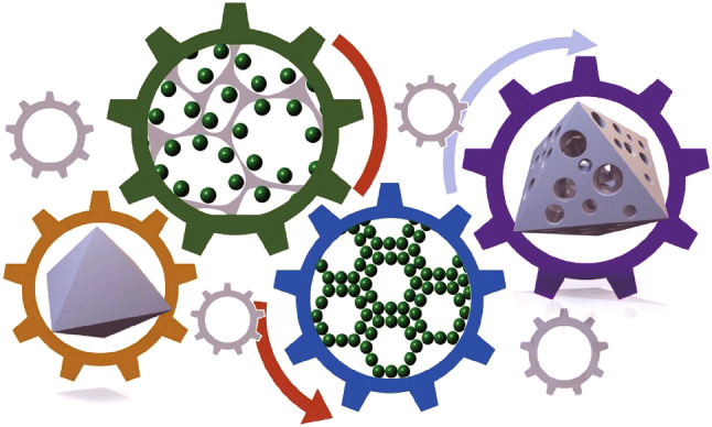
Introduction
The interactions of gases and liquids with porous materials have been a great source of inspiration for scientists tackling problems related to gas separation [1–4], energy storage [5–8], drug delivery [9–12], and catalysis [13–16]. Pores, which can be discrete or can form complete pathways or channels from one surface to another, play a crucial role in gas adsorption and fluid dynamics [17]. Depending on the size of their pores or channels, materials can be classified as microporous (pore diameters of less than 2 nm), mesoporous (pore diameters between 2 and 50 nm), or macroporous (pore diameters above 50 nm) [18]. There has been a recent trend towards the development of new porous materials incorporating pores with different size regimes to form hierarchical systems with interconnected pores and entirely new properties for desired applications. While the concept of introducing meso- and macropores into microporous materials has been extensively investigated in zeolitic porous systems [19–21], development of metal–organic frameworks (MOFs) with open framework structures comprised of metal nodes and organic ligands has seen a rapid expansion of recent research interest. Advances in synthetic chemistry have reported numerous MOF structures (> 70,000 structures reported so far [22]) with potential use in gas storage [23–25], gas separation [26–29], catalysis [30, 31], carbon dioxide capture [32–34], and as semiconductor materials [35, 36]. As the vast majority of MOF materials are microporous, great interest has developed in the creation of multiple porosities in these materials. A number of excellent reviews on hierarchical MOFs have recently been published [37, 38] and focused on MOFs containing micro- and mesoporosity. The current review emphasises the recent achievements in the development of specifically macroporous hierarchical MOF structures which, though important, are under-represented in the MOF field. Macropores are desirable in hierarchical porous materials for enabling faster molecular diffusion and mass transfer, which is especially important for applications involving large molecules, viscous solutions or applications involving high throughput with low pressure gradients.
The benefits of a hierarchical structure for catalytic applications have been well established in purely inorganic systems. For example, hierarchical mesoporous–macroporous structures in high internal phase emulsion (HIPE) template halloysite nanotubes showed greatly improved catalytic activity for the conversion of cellulose to 5-hydroxymethylfurfural because of the catalyst’s increased permeability and mass transfer efficiency [39]. Similarly, the macroporous nature of the support in hierarchical flower-like TiO2 superstructures helps in facilitating more efficient photo-degradation of large dye molecules such as methyl orange [40]. The degradation of Rhodamine B under visible light irradiation using hierarchical core–shell Fe3O4/WO3 was tested by Xi et al. [41], showing that the combination of mesoporous and macroporous regions enhances the photocatalytic activity with almost 100% decomposition achieved after 90 min compared to < 20% and 50% for the iron(iii) oxide core and tungsten(vi) oxide, respectively. In this case, the large voids between the Fe3O4 and WO3 in the hierarchical structure were deemed to synergistically reduce the recombination rate of photogenerated electron–hole pairs, further improving the photocatalytic degradation. The importance of pore size in directing catalysis was further illustrated by Feng et al. [42] using a hierarchical MOF composite comprised of PCN-222 (also known as MOF-545) and ZIF-8 to achieve size-selective catalysis. The PCN-222(Fe)@ZIF-8 composite was exposed to two molecules sensitive to oxidation by PCN-222, namely o-phenylenediamine (o-PDA) (0.5 × 0.5 nm) and 2,2′- azino-bis(3-ethylbenzothiazoline-6-sulphonic acid) (ABTS) (0.7 × 1.6 nm). While PCN-222 successfully catalysed the transformation of o-PDA, the catalysis of the larger ABTS molecule was hindered due to constricted diffusion through the small pore size window of ZIF-8. Thus, considering the added value of hierarchical structure in these inorganic systems, the ability to fabricate hierarchically porous MOF structures may be similarly beneficial when considering future practical applications.
The nature of the porosity in a material can be determined by various characterisation techniques, which can be generally grouped into use of fluid penetration, scattering, and imaging. Fluid penetration techniques involve the filling of pores with a liquid or a gas, to obtain information on the pore sizes and volumes. For MOFs (conventionally microporous materials), gas sorption (generally with nitrogen at 77 K up to 1 bar pressure) is the most common characterisation method to establish the specific surface area, pore volume, and pore size distributions. To obtain this information, the gas sorption isotherms are modelled using standard and widely accepted approaches such as the Brunauer–Emmett–Teller (BET) method for calculating surface area [43], density functional theory (DFT) and the Horvath–Kawazoe (H–K) method for calculation of the pore size distribution in the micropore region, and the Barrett–Joyner–Halenda (BJH) for mesopore distribution [44, 45]. However, nitrogen sorption at 77 K will typically not provide information on macropores larger than 100 nm [44]. For materials containing pores in the mesopore and macropore range (~ 4 nm–60 µm), an alternative method is mercury intrusion porosimetry, which uses non-wetting mercury to penetrate the pores under pressure [44, 46]. While this method can produce a macroporous size distribution in robust porous materials, it has the disadvantages of using a toxic compound (mercury) for the characterisation, cannot be used on soft or deformable structures, and (unlike gas sorption) is destructive to the sample.
Scattering techniques, which involve bombarding the sample with, for example, X-rays, neutrons or electrons to obtain a pattern, can be non-destructive while still enabling characterisation of the porosity. While powder X-ray diffraction (PXRD) and single-crystal X-ray diffraction (SXD) are commonly used to study the microstructures of crystalline porous materials, small angle X-ray scattering (SAXS) can be used to probe the variations in scattering length density which occur over distances exceeding typical interatomic spacing to determine larger particle or pore sizes. Hence, SAXS can be used to calculate pore size distributions in porous materials (1–100 nm range) and can be used for both crystalline and non-crystalline materials, and for materials having regular (but perhaps non-crystalline or disordered) porosity [47]. Both neutron scattering and X-ray scattering can be used to provide information on the pore dimensions in a bulk sample, unlike fluid penetration, which can only give information on interconnected pores that are accessible to penetration by the fluid (“open” porosity), scattering can provide information on isolated or “closed” pores in the material. However, for scattering techniques to be used for characterisation of porosity, there needs to be appropriate scattering length contrast between the pores and the surrounding material, which can be difficult in the case of X-ray scattering from MOFs, where the voids are often filled with air and the materials contain predominantly light organic materials such as C or H. Increased contrast may be achieved by the filling of the pores with a suitable contrast agent [48], which may have the undesirable effect of distorting the pores, for example, in the case of flexible MOFs, or where there is a soft, compliant matrix, such as a hydrogel. In specific cases, where the scattering length density contrast is too small for X-rays, small angle neutron scattering (SANS) can be used [49]. As neutron scattering length varies independent of atomic number, even light atoms such as hydrogen and carbon can be easily distinguished using neutrons [50], but the need for a neutron source means this is a far less widely used technique.
As can be seen throughout the literature, imaging is by far the most common technique to visualise the macropores appearing in MOFs due to widespread accessibility of the technique and ease of use. Microscopy can provide valuable insight into the shape and spatial distribution of pores. For small macropores (e.g. below 10 µm), scanning electron microscopy (SEM) and transmission electron microscopy (TEM) can be used to image porosity and can be performed in a very straightforward way on a very small amount of sample. However, these imaging methods are not bulk techniques (with SEM in particular being restricted to definition of surface features) and can only observe a small number of particles and therefore may not be representative of the bulk porosity. For imaging of larger macropores (from a few tens of microns to millimetres in size), optical microscopy can be useful, but cannot provide information on the connectivity or tortuosity of the interior pore network in monolithic structures. The ability of X-rays to penetrate light materials can be used in X-ray computed tomography (CT), whereby a series of 2D X-ray images of a material are computationally compiled and reassembled to obtain a 3D image [51]. X-ray CT can thus be used to image large pores in monolithic structures, though the resolution of such techniques is currently limited to a few tens of microns [51]. Thus, it can be seen that few characterisation techniques can span the full range of pore sizes. Therefore, as will be shown in this review, due to the complexity of such materials, a combination of several techniques may be needed to obtain a full description of the macroporosity in hierarchical MOF structures.
The routes to formation of such complex structures are equally varied. In terms of approaches to increase pore dimensions in MOFs using synthetic chemistry, the typical methods used in MOF synthesis to produce mesopores (such as extending ligand lengths or enlarging building blocks) are of limited use in the creation of much larger macropores. This is due to the difficulties in stabilising these pores against collapse upon desolvation during activation [52]. Hence, the formation of macroporosity (rather than mesoporosity) in MOFs necessitates the use of very different fabrication approaches. In this review, we focus on the synthetic strategies and challenges of creating MOFs with pore structures containing macropores and provide readers with a wider scope of the strategies available for fabrication of hierarchical macroporous MOFs.
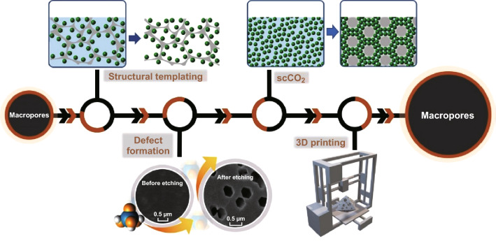
We grouped the macroporous MOF structures that have been studied under four broad approaches, which are presented in order of most commonly reported method to least reported as follows: macroporous MOFs synthesised via structural templating, defect formation, use of compressed or supercritical CO2 (scCO2), and 3D printing routes (as summarised in Fig. 1 and Table 1).
Fig. 1.
Schematic representation of synthetic methods for hierarchical MOFs with macroporosity
Table 1.
A summary of preparation techniques, crystallisation routes, and templates for the formation of hierarchical MOFs with macroporosity
| Preparation techniques | Macropore formation route | Templates, substrates, modulators or reagents used | MOFs prepared using these methods | References |
|---|---|---|---|---|
| Hard structural templating | Direct synthesis | Macroporous carbon derived from kenaf stem, polymer-derived ceramic (PDC) foam, oxide-bonded silicon carbide and alumina (Al2O3), ceramic foams (CF), copper foam | HKUST-1, CAU-10, UiO-66 (Zr), MOF-5 | [59, 62, 63, 66] |
| Post-synthetic treatment | Nickel foam | MIL-101 (Cr) | [60] | |
| Soft structural templating | Direct synthesis | Cellulose solution, konjac glucomannan, graphene oxide, melamine foam (MF), three-dimensional polystyrene (PS), N,N-dimethyloctylamine (DMOA), polyacrylamide (PAAm) | ZIF-8, ZIF-9, ZIF-12, PCN-224, HKUST-1 | [69, 70, 74–78] |
| Post-synthetic treatment | Melamine sponge | ZIF-67 | [71] | |
| Defect formation | Direct synthesis (linker modulation) | Alkyl chains, monocarboxylic acids | MOF-5, UiO-66 | [92, 93] |
| Post-synthetic treatment (acid etching) | Phenolic acid, cyanuric chloride and tetraethylamine (TEA), phosphoric acid, hydroquinone, H3BO3 and NaCl | ZIF-8, IRMOF-3, MIL-101(Fe), HKUST-1 | [94–96, 98, 99] | |
| Use of compressed or supercritical CO2 | Post-synthetic treatment (scCO2 drying) | Emulsion | HKUST-1, AlBTC, AlBDC | [109, 110] |
| Direct synthesis (expanded solvent) | N-EtFOSA/TMGT solution, DMF, DMSO/MeOH | Zn-BTC, HKUST-1, Co-BTC | [113–115, 120] | |
| 3D printing | Post-synthetic incorporation | Polyvinyl alcohol (PVA), trimethylolpropane propoxylate triacrylate (TMPPTA), polylactic acid (PLA) | MOF-74 (Ni), UTSA-16 (Co), UiO-66, ZIF-8 | [146–148] |
| Direct synthesis | Anionic 2,2,6,6-tetramethylpiperidine-1-oxylradical-mediated oxidised cellulose nanofibers (TOCNFs) | ZIF-8 and MIL-100 (Fe) | [149] |
Structural templating involves use of a template containing macroporous voids to produce a macroporous composite structure by directly growing the crystalline MOF either on or around a template. The template can be “hard” (e.g. a foam or porous monolith) or “soft” (e.g. a gel or emulsion) and can be retained or removed after templating.
Defect formation describes the disruption of the periodic crystalline structure of the MOF e.g. by incorporating a sizeable ligand during synthesis which introduces a porous defect or by selective removal of sites to produce pores, e.g. via post-synthetic acid etching of MOF single crystals.
Compressed or supercritical CO2 has been used extensively for activation of MOFs [53] to remove solvents and soft templates to produce porous aerogel structures, but scCO2 has also recently been shown to be useful in expanded solvent systems for producing macroporous voids during direct synthesis of MOFs.
The recent use of 3D printing combines MOFs with binders to create MOF-based inks capable of forming hierarchical monoliths on deposition. This represents a new method with potential to enable the construction of hierarchical monoliths with complex geometries.
Most of these methods can be employed either using MOF precursor solutions (termed “direct synthesis”) or using pre-formed MOFs (“post-synthetic treatment”), as shown in Table 1.
Preparation Techniques for Hierarchical MOFs with Macroporosity
Structural Templating Method
The most common approach to the introduction of macropores into an intrinsically microporous MOF is using structural template to form a hierarchical structure. As demonstrated for a multitude of other porous material systems, the macroscopic shape and the pore size of the resulting hierarchical structures can be well controlled through judicious choice of template [54–58]. The resulting hierarchical porous MOF structures could potentially exhibit improved properties such as more rapid molecular diffusion compared to the respective non-hierarchical MOFs, better mechanical or thermochemical stability, and immobilisation of nanoparticulates. Thus, they are preferentially used in some applications that require easy integration and regeneration (e.g. for adsorbent systems [59, 60]) or exceptional mass transfer (e.g. for catalyst supports [61]).
The macroporous MOF structures deriving from the template approach can be divided into two main categories: one is that the template remains in the final MOF structure, forming a composite material, and the other is that the template is sacrificial and removed to obtain a macroporous structure in the pure MOF (often called a MOF aerogel or a foam). Templates can be broadly grouped into “hard” and “soft” structural templates.
Hard Structural Templating
Hard templates may be carbons [62], ceramics [59, 61, 63–65], and metals [60, 66–68]). They are typically in the form of monoliths, porous membranes, or foams [60, 62, 69]. Because hard templates are difficult to be removed, the majority of these templates act as supports, resulting in macroporous composite MOF structures.
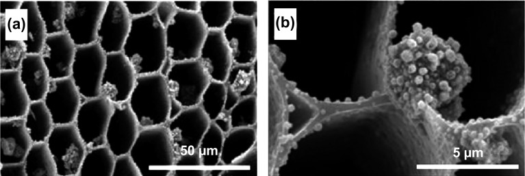
As an example of direct MOF synthesis on a hard template to obtain a hierarchical structure with macropores, Xie et al. [62] grew HKUST-1 MOF crystals on three-dimensional kenaf stem-derived macroporous carbons (3D-KSCs), forming a composite material with a macroporous structure. In this work, it was shown that a large number of smooth-faced octahedral HKUST-1 crystallites with maintained morphology were formed on the surface and inner walls of the macroporous 3D-KSC template (Fig. 2a, b), with the amount of HKUST-1 loaded onto the template increasing with increased reaction time. The as-obtained composites were tested for electrochemical sensing of glucose, showing very promising activity with a relatively wide linear range (15.84 µM–5.62 mM), low limit of detection (4.8 µM), and a high sensitivity (28.67 µA mM−1 cm−2). The excellent electrocatalytic activity was attributed to the presence of macropores in the hierarchical structure which was led to improved mass transfer of the glucose. Using a similar hard template, Sandra et al. [59] synthesised a series of silicoboron carbonitride (Si/B/C/N) polymer-derived ceramic (PDC) foams with micro-/macroporosity using silicon and carbon high internal phase emulsions (HIPE) as exo templates and boron-modified polycarbosilazane as an organosilicon precursor. HKUST-1 was impregnated by growing the MOF inside the macropores of the PDC to form Si/B/C/N@MOF composite foams, allowing faster and more efficient uptake and release kinetics, in particular for CO2 capture.
Fig. 2.
SEM images of HKUST-1/3D-KSCs800 at different magnifications, showing the growth of microporous HKUST-1 crystals on the 3D-KSCs800 macroporous template. Reprinted with permission from Ref. [62].
Copyright 2018 Elsevier B.V
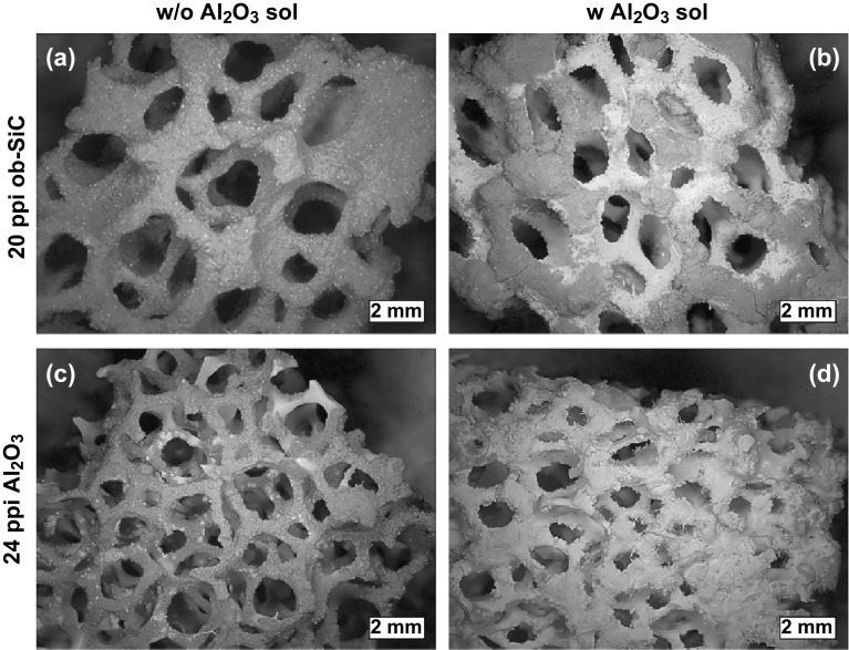
Direct synthesis of MOFs on hard templates has also been shown by Betke et al. [63] and to be readily adaptable to a variety of MOF types, with a range of macroporous MOF@ceramic foam composite materials being formed by growing MOFs such as HKUST-1, CAU-10, MIL-101(Cr), and UiO-66(Zr) on macroporous oxide-bonded silicon carbide (ob-SiC) and alumina ceramic foams (CF). In these cases, the MOFs were being tested for use in sorptive heat pump/heat storage applications; the macroporous ceramic structure not only had benefits for the mass transfer and adsorption/desorption kinetics (which had the effect of decreasing cycling times), but also enhanced heat transfer in comparison with the powdered MOF, increasing the potential for adsorptive cooling. The surface properties of the CF were modified by silanisation using aminopropyl triethoxysilane/terephthaloyl chloride treatment prior to the MOF crystallisation to obtain a thick homogeneous MOF coating on the surface. The thickness of the MOF on the surface was also influenced by an alumina sol coating on the cellular CF support before silanisation, as supported by the SEM images of HKUST-1 on the surface without (Fig. 3a, c) and with (Fig. 3b, d) alumina sol coating. The coating thickness of HKUST-1 crystals ranged between 112 and 264 µm for the ob-SiC-based composites and between 36 and 151 µm for the HKUST-1@alumina composites. Similarly, Hu et al. [66] reported a facile synthesis of hierarchical porous MOF-5 structure using a copper foam as a template, for removal of volatile sulphides from plant sources. The MOF composite was prepared by solution impregnation of zinc nitrate and terephthalic acid into a pre-treated copper foam. The macroporous MOF monolith was tested for the extraction of volatile organic sulphur compounds with detection values of 6.0–54.6 µg g−1.The extraction process could be replicated at least 200 times, indicating that the formation of the macroporous composite structure may have been beneficial for the stability of MOF-5, which is widely recognised for being prone to hydrolysis, particularly in humid environments.
Fig. 3.
SEM images of HKUST-1 coatings on ob-SiC and Al2O3 ceramic foams a, c without and b, d with preliminary alumina sol coating. The HKUST-1 coating layers on the ob-SiC composites are thicker than those on Al2O3 composites.
Reprinted with permission from Ref. [63]. Copyright 2016 Elsevier Inc
While the direct crystallisation of MOFs onto a macroporous template is the most commonly used method, in addition to the direct synthesis and growth approaches discussed above, a microporous MOF can also be endowed with a macroporous structure by combining a macroporous substrate with a pre-formed MOF. For example, Ren et al. [60] prepared MIL-101(Cr) powders and immobilised the nanocrystals on a macroporous nickel (Ni) foam via spray coating. The PXRD pattern of the MIL-101/Ni foam composite showed peaks that corresponded to both MIL-101 powders and Ni foam (Fig. 4a). The incorporation of the MOF crystals on the Ni foam was further evidenced by SEM images, in which the porosity of the Ni foam was reduced by the presence of multi-layered MIL-101 powders on its surface (Fig. 4b). The MIL-101/Ni foam composite was tested for hydrogen storage and the composite with 81 wt% loading of MIL-101(Cr) nanocrystals exhibited a hydrogen adsorption capacity similar to pure MIL-101(Cr) powders. Although an increase in hydrogen uptake was not observed, the immobilisation of MIL-101(Cr) powders onto a macrostructural support provides a facile method to process MOF powders and immobilises the nanoparticulates for applications in practical systems.
Fig. 4.
a PXRD patterns of Ni foam-immobilised MIL-101(Cr) (blue) showing the presence of peaks which correspond to both Ni foam (black) and MIL-101(Cr) nanocrystals (red). b SEM images of Ni foam-immobilised MIL-101(Cr) showing the presence of multi-layered MIL-101(Cr) nanocrystals on the macroporous Ni foam.
Reprinted with permission from Ref. [60]. Copyright 2015 Elsevier B.V. (Color figure online)
Soft Structural Templating
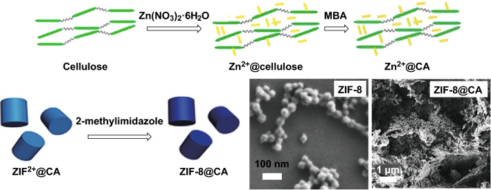
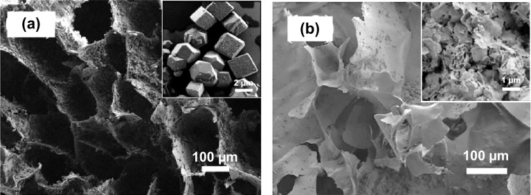
In situations where flexibility of the porous support is desired, soft macroporous templates are sometimes advantageous. Soft templates include surfactants [70], polymers [71–73], gels, and emulsions. Flexible macroporous composite materials were developed by Bo et al. [74]; they reported a facile method for the direct synthesis of a cellulose hybrid aerogel of ZIF-8 (ZIF-8@CA), in which zinc cations were dispersed in a cellulose solution before prompting nucleation reaction with 2-methylimidazole to form the MOF as illustrated by the schematic in Fig. 5. ZIF-type materials are favoured candidates because of their high water stability which is crucial for gel formation without losing the original crystallinity. As shown in the inset of Fig. 5, the resulting hybrid material retained the original ZIF-8 particle size (20–40 nm) with hierarchical porous structures (pore size between 10 and 100 µm). Cr(VI) sorption was performed on this sample, showing a greatly improved uptake in the composite material when compared with a single component. A similar synthetic method was applied to the synthesis of ZIF-9 and ZIF-12 on CA (Fig. 6a and b, respectively) [75], which showed macropores with improved catalytic performance in p-nitrophenol degradation (90% in 1 h). Preparation of a ZIF aerogel via a one-pot strategy was further explored using various templates such as biodegradable konjac glucomannan by deacetylation [76] and graphene oxide [77] and resulted in structures with outstanding photoelectric, mechanical, and thermal properties.
Fig. 5.
Schematic illustrations showing the preparation of ZIF-8@CA and the resulting SEM images.
Reprinted with permission from Ref. [74]. Copyright 2018 Elsevier Inc
Fig. 6.
SEM images of a ZIF-9@CA and pure ZIF-9 inset, and b ZIF-12@CA and pure ZIF-12 inset.
Reprinted with permission from Ref. [75]. Copyright 2018 Elsevier B.V
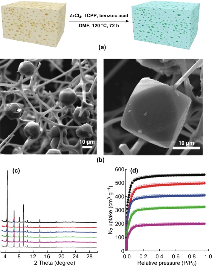
Another example of using soft structural templates in direct synthesis was given by Huang et al. [78], who reported a series of porous coordination network (PCN) MOFs that were integrated into a macroporous monolithic melamine foam (MF) using a one-pot synthesis (Fig. 7a, b), resulting in hierarchical porosity, and a flexible and elastic texture, which was favourable for heterogeneous catalysis. Additionally, the BET surface areas were found to increase with the loading amount of PCN-224(Fe) in the composites (1623–1704 m2 g−1) (Fig. 7d). The positive effect of the macroporous structure on the application of these samples was confirmed in the highly efficient catalytic epoxidation of unsaturated cholesteryl esters. The 2 mol% of PCN-224(Ru) 200%/MF showed an excellent yield (92%) of the corresponding epoxide after 36 h, compared to a yield of 56% using normal PCN-224(Ru) and 0% conversion using a control of pure melamine foam.
Fig. 7.
a Procedure for the preparation of PCN-224 decorated melamine foam composites. b FESEM images of PCN-224(Fe)/MF composite depicting the melamine foam network homogeneously decorated with PCN-224(Fe) microcrystals. c The high similarities between the PXRD patterns of PCN-224(Fe) (grey), PCN-224(Fe)50%/MF (purple), PCN-224(Fe)100%/MF (green), PCN-224(Fe)150%/MF (blue), PCN-224(Fe)200%/MF (red), and PCN-224(Fe)325%/MF (black) indicating the structural stability of the MOF composites. d N2 sorption isotherms of PCN-224(Fe)50%/MF (purple), PCN-224(Fe)100%/MF (green), PCN-224(Fe)150%/MF (blue), PCN-224(Fe)200%/MF (red), and PCN-224(Fe)325%/MF (black). The BET surface areas increased with the increasing loading amount of PCN-224(Fe) in the composites.
Reprinted with permission from Ref. [78]. Copyright 2018 Wiley-VCH Verlag GmbH & Co. KGaA, Weinheim. (Color figure online)
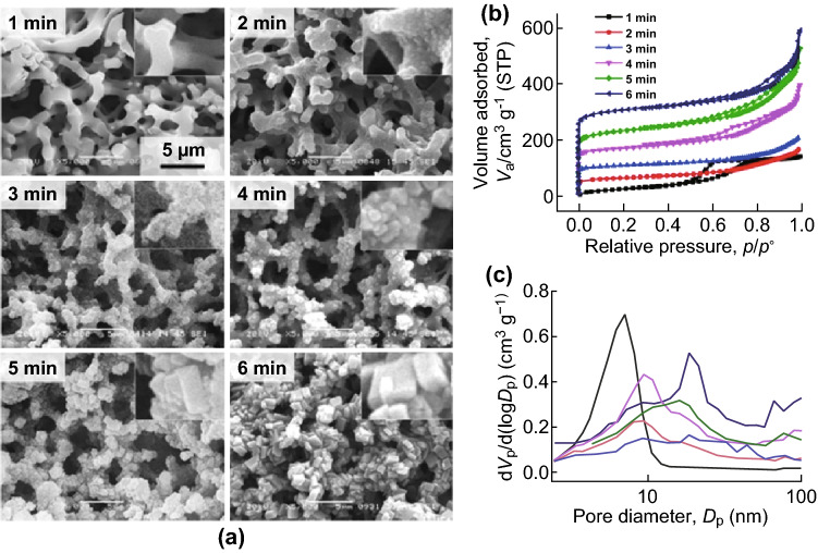
Moitra et al. [79] developed an innovative protocol for the direct synthesis of a macroporous monolithic HKUST-1 composite by conversion of Cu(OH)2-based networks in a polyacrylamide (PAAm) gel. The presence of PAAm in the original (oxy) hydroxide network supported the scaffold of Cu(OH)2 by chelating the copper ions with the N-groups in the amide, resulting in gelation and producing a co-continuous network which was converted to HKUST-1 through coordination by H3BTC. The macropore size within the aggregated particles could be controlled by changing the amount of PAAm from 0.3 to 1 g or by varying the immersion time in H3BTC between 3 and 6 min (Fig. 8a). In addition, enhancements in N2 uptake (Fig. 8b) and pore size (Fig. 8c) were reported with increased immersion times, corresponding to higher MOF loadings. The resulting HKUST-1 monolith showed high crystallinity, a high surface area of 1315 m2 g−1, and good mechanical properties (stress values at catastrophic failure of 1.5 MPa), which are promising for possible applications in continuous flow reactors, which require both high mass transfer and immobilisation of the MOF.
Fig. 8.
a SEM images of the conversion of Cu-06 to HKUST-1 with 1-min time intervals, showing the growth of polyhedral crystallites with the preservation of the co-continuous macroporous gel structure. All the images are in the identical magnification. b N2 sorption isotherms and c BJH pore size distributions with respect to increased immersion times. The BET surface areas and pore sizes increased with immersion times.
Reprinted with permission from Ref. [79]. Copyright 2015 Royal Society of Chemistry
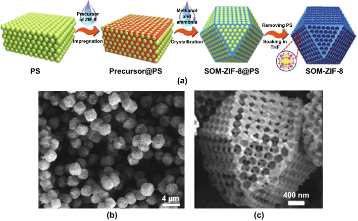
Soft templates are also beneficial where facile template removal is desired. As an example, a polymer has been used as a sacrificial soft template to form a macroporous MOF, and a hierarchical SOM-ZIF-8 MOF was formed by impregnating ZIF-8 precursors into the interstices of three-dimensional polystyrene (PS) spheres in a mixture of methanol/ammonia (Fig. 9a) [69]. SEM image confirmed that ZIF-8 single crystals were uniformly grown around the PS template and the overall network displayed a tetrakaidecahedron morphology (Fig. 9b, c). A highly structured macroporous framework could be accessed by dissolving the PS template in THF and subsequently activated via removal. The presence of macropores in the MOF was confirmed by mercury intrusion porosimetry, and the size of the macropores could be modified (80–470 nm) by changing the diameter of the polystyrene templates. Furthermore, Shen et al. reported that the single-crystal growth was governed by the solvent system and the crystal size was conveniently tuned by modifying the ratio of the methanol/ammonia mixture.
Fig. 9.
a Schematic diagram of SOM-ZIF-8 synthesis. SEM images of b SOM-ZIF-8 and c an isolated crystal of SOM-ZIF-8 showing the tetrakaidecahedron morphology.
Reprinted with permission from Ref. [69]. Copyright 2018 The Authors, some rights reserved
Duan et al. [70] reported the soft-templated synthesis of a HKUST-1 framework that contained micro-, meso-, and macropores, using a N,N-dimethyloctylamine (DMOA) surfactant as a sacrificial template. The role of the DMOA as a template was demonstrated by mesodynamics simulation in which the introduction of DMOA into the reaction mixture resulted in the formation of supramolecular micelles. Subsequently, the MOF precursors [i.e. a mixture of hydroxy double salt (Zn and Cu)] and benzenetricarboxylic acid (H3BTC) were added and self-assembled on the surface of the template micelles at room temperature and then formed the hierarchical porous HKUST–1 upon the removal of DMOA template. SEM images revealed the hierarchical nature of this MOF whereby continuous pore voids were formed between the nanoparticles. TEM further confirmed the abundance of mesopores and macropores (pore sizes of 40–100 nm) in the final product. Because of the presence of macropores which contribute to high molecular diffusion, the hierarchical MOF exhibited a high toluene storage capacity (646 mg g−1 at 298 K), representing a 25 wt% increase compared to that for the non-hierarchical HKUST-1 (516 mg g−1) [80]. This value is also much higher than other microporous MOFs and zeolites [81–83]. The use of surfactants in the preparation of such hierarchical MOFs introduces a new way to allow the degree of porosity to be readily tuned by adjusting the amount and type of surfactant used.
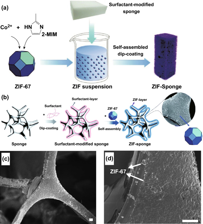
In addition to such direct synthesis methods, it may also be the case that pre-formed MOFs can be deposited onto a macroporous soft template using post-synthetic treatment. For example, Lin et al. [71] used a surfactant-assisted dip-coating method to synthesise a flexible three-dimensional hierarchically porous ZIF-67/melamine sponge composite (as illustrated in Fig. 10a, b). The ZIF nanocrystals were dip-coated on the surface of a surfactant-modified pliable melamine sponge by immersing it in ZIF-67 suspension while stirring for 3 h. The self-assembly of MOF crystals on the modified melamine sponge occurs via electrostatic attractions and possibly π–π stacking interactions. The SEM image (Fig. 10c, d) showed that the clean, smooth surface of the melamine sponge became roughened by the ZIF-67 coating. Four types of surfactants were used for the modification of the melamine sponge including anionic sodium dodecyl benzene sulphonate (SDBS), cationic cetyltrimethylammonium bromide (CTAB), non-ionic hydrophobic sorbitan monooleate (denoted as SPAN-80), and non-ionic hydrophilic Triton X-100 to study the effect of surfactant properties on the ZIF-67 loading. It was found that increasing the concentration of CTAB and Triton X-100 did not increase the ZIF-67 loading. However, an increase in ZIF-67 loading was observed when the melamine sponge was modified by SDBS and SPAN-80. According to zeta potential measurements, in the testing pH range, Triton X-100 was found to be neutral, ZIF-67 and CTAB displayed positive surface charges, and SDBS and SPAN showed negative surface charges. The increase in ZIF-67 loading with SDBS and SPAN surfactants was attributed to the electrostatic attraction between the positively surface charged ZIF-67 and negatively surface charged SBDS and SPAN. This approach of synthesising the ZIF-67/melamine sponges could be further used to fabricate various shapes such as fibres or membranes and can be used as adsorbents for the removal of toxic large molecule pollutants like malachite green dye.
Fig. 10.
Schematic illustrations showing the preparation of ZIF–sponge, showing a surfactant-assisted dip-coating self-assembling process and b surface modification of the sponge skeleton first with a surfactant and then ZIF-67. c, d SEM images of ZIF–sponge prepared with the assistance of SDBS under different magnifications (the scale bar is 2 µm), showing ZIF nanocrystals were dip-coated on the surface of melamine sponge.
Reprinted with permission from Ref. [71]. Copyright 2015 Royal Society of Chemistry
The use of structural templating agents remains the most established method in the formation of macroporous MOFs due to the wide range of templates and templating agents that can be employed in this technique. As can be seen by the examples given thus far, the resulting hierarchical structures generally adopt the shape of the templating agents. It was also shown that these templates could be introduced either in the reaction solution during MOF synthesis or in the precursor solution where the prepared MOFs were dispersed. The final materials could be obtained as MOF-based composites with the template retained or as pure MOF superstructures without the template. When the templating agents are incorporated to produce the final composite MOF structures, in addition to the immobilisation of the MOF crystals, they may also contribute to improved mechanical and thermochemical stability of the MOF composites. In the case of MOFs with sacrificial templates, washing processes are required to remove the templates. In some cases (such as coordination polymer frameworks, silicates and MCM-41), it can be detrimental to the stability of the pore structures [84–87]. Furthermore, incomplete removal can lead to occlusion of the pores and therefore loss of functionality for gas sorption/catalytic reactions. In terms of potential uses, the MOFs formed via this method have been utilised in various applications from catalytic applications, heat and mass transfer to extraction of volatile compounds.
Defect Formation Method
From the point of sustainable processing, the ability to form macroporosity in the absence of sacrificial templates or scaffolds would be preferable. A commonly used strategy for obtaining hierarchical porous MOFs without using templates is through direct introduction of defects into the microporous structures. This process could be carried out using either in situ synthetic methods (e.g. using linker modulation) or using post-synthetic treatment (e.g. via acid etching). Linker modulation and linked labilisation methods predominantly produce mesoporous defects in microporous MOFs. Yuan et al. demonstrated using a pro-labile organic linker for the synthesis of PCN-160 MOF. The defect in the pre-formed MOF was introduced by splitting this pro-labile linker into removable monocarboxylate moieties under acidic conditions, which improved their gas adsorption and catalytic properties [88]. Similarly, Kim et al. created mesoporous defects in microporous HKUST-1 using an acetic acid fragmented linker co-assembly method. A small amount of acetic acid removed the BTC linker to create mesoporous defects. On increasing the amount of acetic acid, metal clusters in the MOF were removed, which resulted in interconnected defect sites and mesoporous channels inside the MOF, which enhanced the methane storage capacity in the defective MOF [89]. These methods have been employed extensively in numerous studies to functionalise meso- and macropores with straightforward synthetic procedures and a number of effective mechanisms have been demonstrated [90, 91], but there are now additional reports of using similar methods for the production of macroporous structures.
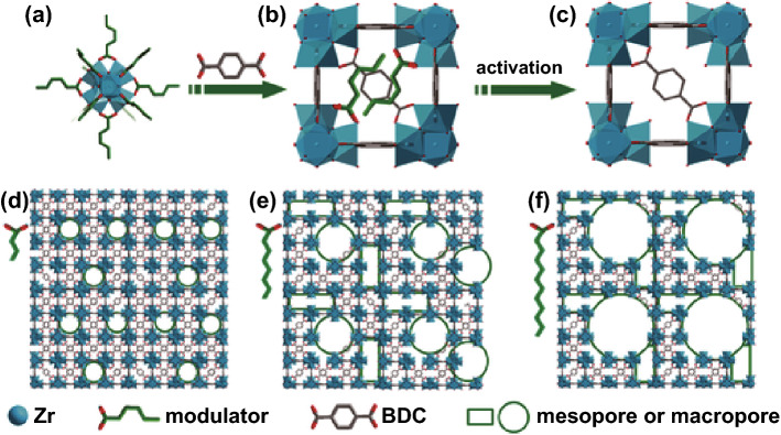
Examples of macroporous materials formed by in situ linker modulation methods include the introduction of extended aliphatic chains to MOF linkers to obtain sponge-like or pomegranate-like crystallite structures in MOF-5 [92] and using alkyl chains as modulators for macropore formation in UiO-66 [93]. In the case of the hierarchical macroporous MOF-5 structures, the formation of either the sponge-like (spng-MOF-5) or pomegranate-like (png-MOF-5) structures was the result of incorporating different proportions of the linkers containing the large void-forming alkyl chain (50% and 30% incorporation, respectively). The modulators were shown by gas sorption to prompt formation of additional mesoporosity and macroporosity into MOF-5, which influenced the CO2 uptake properties of the different structures. However, the additional beneficial effects of having such an interconnected macroporous structure which was evidenced from the SEM would have been more obvious if a bulkier adsorbent than CO2 had been employed. In the case of the defective UiO-66 synthesised by a modulator-induced defect formation strategy described by Cai et al. [93], Zr4+ ions reacted with less than stoichiometric amounts of BDC2− linkers and COO− ions in monocarboxylic acids as a modulator to pre-coordinate Zr-oxo clusters. The alkyl chain on the modulators linked these clusters to create large voids during synthesis (Scheme 1). The pore sizes were tuneable by changing alkyl chain length and the molar ratio of Zr to H2BDC. The ability to transport large molecules through the defect structure was demonstrated using the catalytic methanolysis of styrene oxide. The results indicated that the hierarchical porous UiO-66 with additional mesopores exhibited superior catalytic activity when compared to the normal MOF. It was foreseen by the authors that macropores could be obtained with further expansion of the alkyl chain length in the modulator. However, they noted that the high pKa values of elongated alkyl chains could decrease the solubility and coordination ability of the modulator with Zr-oxo clusters, which might result in adverse effects such as pore shrinkage.
Scheme 1.
Schematic illustration of the synthesis of HP-MOFs with adjustable porosity using UiO-66 as an example.
Reprinted with permission from Ref. [93]. Copyright 2017 Wiley-VCH Verlag GmbH & Co. KGaA, Weinheim
An alternative approach to direct synthesis of defective MOFs with macropores is via the post-synthetic etching of prepared microporous MOFs. This can be done either by an acid etching mechanism whereby selected acid molecules diffuse through the MOF structure, forming large voids over time, or by synergistic etching where bulky acid molecules modify and protect the MOF surface to obtain the holey materials.
Koo et al. [94] investigated a size-selective acid diffusion method for the post-synthetic treatment of MIL-100 (Fe) using phosphoric acid (d = 0.61 nm) as the etching agent. During the etching process, phosphoric acid could specifically diffuse through the hexagonal windows (d = 0.89 nm) but not through the pentagonal windows (d = 0.49 nm) of MIL-101(Fe) to form macropores in the framework, preserving the microporous nature by selective removal of metal nodes and BTC linkers. The framework crystallinity and morphology of the MOF crystals were well maintained even after post-synthetic treatment. Note that this process cannot be achieved by employing smaller acids such as HCl (d = 0.34 nm) in the same manner. This is simply because the small cages could also be attacked during etching, leading to complete collapse of the MOF structure. This etching method seems to be effective for the creation of hierarchical porous MOFs with tuneable pore sizes. However, as mentioned in the literature [94], these approaches are only applicable for highly water-stable MOFs.
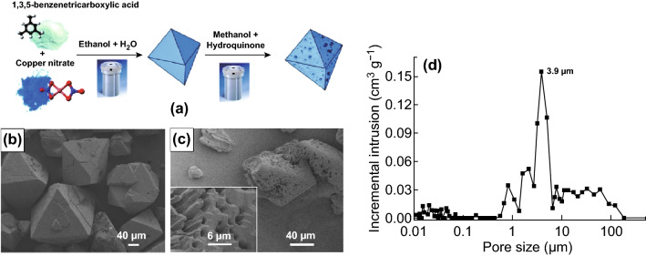
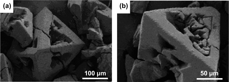
A similar idea was developed by Ahmed et al. [95] with their report on solvothermal post-synthetic modification of microporous HKUST-1 (Fig. 11a). By etching prepared HKUST-1 in weakly acidic hydroquinone (pKa = 9.85 in water) at 150 °C for 16 h, macroporous channels with pore sizes ranging from 500 nm to 10 µm (via Hg intrusion porosimetry—see Fig. 11c, d) were observed within HKUST-1 microparticles while retaining the structure of the large crystallites and high surface area. The etching process was further investigated at 120 and 180 °C for 16 h, and 150 °C for 72 h, indicating that the degree of macropore formation was dependant on reaction time and temperature. By using ICP analysis of HKUST-1 on the etching solution, it was found that Cu(II) ions were selectively removed from the framework when using a hydroquinone solution. This was also confirmed by a slight distortion in the single-crystal XRD patterns, likely caused by Cu deposits generated during the modification process. Other reagents (including H3BO3 and NaCl) were also tested in this process. Etching HKUST-1 in H3BO3 and NaCl resulted in the formation of large etched holes at the centre of the particles (Fig. 12a, b), yielding additional macropores in this MOF. The synthesised macroporous HKUST-1 crystals were then successfully used to separate styrene and ethyl benzene when packed into a high-performance liquid chromatography (HPLC) column.
Fig. 11.
a Schematic representation for the preparation of HKUST-1 particles and the subsequent modification to produce macroporous HKUST-1 particles. b SEM image of HKUST-1 microparticles prepared by solvothermal synthesis with water–ethanol (1:1 v/v). c SEM image of modified HKUST-1 particle with hydroquinone at 150 °C for 16 h, showing the macroporous microparticles. d Macropore size distribution as measured by Hg intrusion porosimetry, with an intrusion pore volume 2.65 cm3 g−1, for the modified HKUST-1 particles.
Reprinted with permission from Ref. [95]. Copyright 2014 Royal Society of Chemistry
Fig. 12.
SEM images of HKUST-1 particles modified by different reagents other than hydroquinone. a in 50 µL boric acid aqueous solution at 150 °C for 16 h and b in 50 µL NaCl aqueous solution at 150 °C for 16 h, showing some large etched holes were formed from the centre of the particles.
Reprinted with permission from Ref. [95]. Copyright 2014 Royal Society of Chemistry
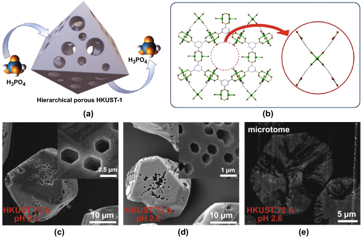
Prompted by the size-selective acid diffusion mechanism, a defective HKUST-1 was synthesised by Doan et al. [96] using a phosphoric acid etching agent (Fig. 13a). The mechanism of macropore formation was explained by the disassembly of one copper cluster and the paddle wheel linkers in the framework of HKUST-1 by phosphoric acid (Fig. 13b). The degradation problem of HKUST-1 in water was effectively solved by employing DMSO and methanol as dilute solvents. More interestingly, a range of interconnected highly geometrical macropores were observed with the extent of porosity being tailorable by controlling time and pH in these systems (Fig. 13c–e). It is anticipated that the macropores in these MOFs would improve the diffusion and accessibility of bulky molecules to active sites in catalysis, as was shown to be the case of defective UiO-66 which showed improved catalytic performance in Lewis acid-catalysed reactions [97].
Fig. 13.
a, b Schematic representation of the etching process for HKUST-1 using phosphoric acid, showing phosphoric acid diffusing into HKUST-1 to form a hierarchical porous structure (a) and the disassembly of a cluster and 4 linkers (b). c–e SEM images of HKUST-1 etching in phosphoric acid using DMSO and MeOH as dilute solvents at pH 2.8 (c) and pH 2.6 (d, e), showing interconnected geometrical macropores after etching.
Reprinted with permission from Ref. [96]
As an extension to the idea of size-selective acid etching, another post-synthetic process, termed “synergistic etching and surface functionalisation”, was reported by Hu et al. [98]. In this study, weak bulky phenolic acids such as gallic acid and tannic acid were used to provide free protons that penetrated into the MOF crystals to form a hollow structure. Interestingly, these acids with large molecular sizes simultaneously blocked the exposed surface of ZIF-8, leading to the preservation of the parent crystalline framework of MOF in the outer shell. Yoo and Jeong [99] reported that by etching IRMOF-3 with cyanuric chloride and tetraethylamine (TEA), protons released from the modification can create a mesoporous structure or even macroscale defects if the etching process proceeds further. In this case, TEA was used as a proton scavenger to prevent the complete dissolution of IRMOF-3 in cyanuric chloride, thus preserving the MOF crystallinity.
From the above examples, it can be seen that acid etching approaches for the preparation of hierarchical macroporosity in MOFs are a comparatively facile procedure compared to templating methods, as they can be carried out as a post-synthetic step on larger samples of MOFs. Furthermore, it is possible for the defective MOFs resulting from these approaches to possess well-defined crystal structures and preserve their external morphology after acid etching, though judicious choice of the etching agent and etching conditions are essential to obtain controllable macroporosity in MOFs without the loss of crystallinity or complete dissolution of the crystalline structure. While water unstable MOFs were considered as limited candidates in some etching mechanisms, this could be solved by varying the dilute solvents employed. The nature of the interactions of various solvents with MOF frameworks therefore needs to be well understood to generate a method applicable to different MOF systems.
Compressed or Supercritical Carbon Dioxide Method
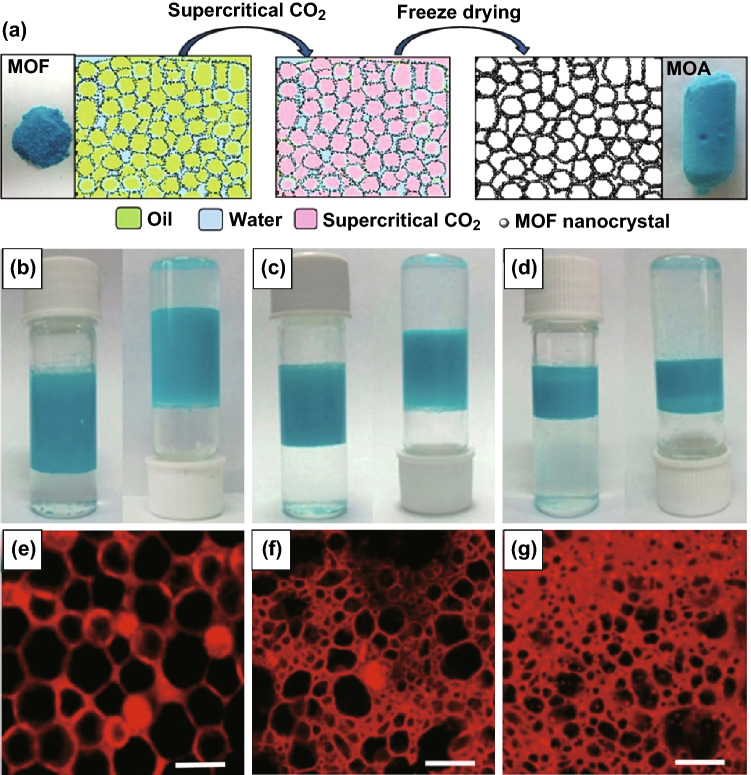
Compressed or supercritical carbon dioxide has been widely applied to a range of MOF processing steps including crystallisation [100–102], impregnation [103], dispersion [104], drying [105], and activation [106, 107]. Formation of highly porous materials will generally benefit from the use of supercritical drying (typically scCO2), with the low viscosity and high diffusivity of supercritical fluids being recognised as being especially vital for activation of large pores, to avoid pore collapse in MOFs during solvent removal [108]. An alternative approach for generating microporous structures in MOFs, as opposed to depositing a MOF on a porous template which has then to be removed, is to directly form microporous MOFs into an aerogel, establishing free-standing monoliths with added macroporosity. Drying with scCO2 has been illustrated as a key post-synthetic treatment step for synthesis of macroporous MOF/aerogel composites (MOFAC) in the absence of a polymer template. In this synthesis, a prepared MOF may be added into an emulsion to form a stable network, before drying by scCO2 to obtain an aerogel. Recently, a strategy to synthesise HKUST-1 MOF-stabilised high internal phase emulsions (HIPE) at the oil–water interface was described by Zhang et al. [109]. After removing the liquids with scCO2 (Fig. 14a), the as-assembled MOF aerogel presented a macroporous structure with an outstanding volume expansion and low density of 0.015 g cm−3 (Fig. 14e–g); the macropore size could be easily tuned by changing the initial oil volume fraction of the emulsion structures without the need of single-use sacrificial polymer templates (Fig. 14b-d). Similarly, Li et al. [110] reported a two-step gelation of MOF nanoparticles, in which AlBTC and AlBDC gels with different metal-to-ligand ratios and concentrations were formed at elevated temperatures before exchanging the pore liquid with liquid CO2 under subcritical extraction to produce meso-/macroporous “Al-MOA” aerogels. These Al-MOAs were tested for the uptake and transportation of bulky molecules, and the retention of hierarchical porosity was demonstrated by uptake of Congo red (CR) and brilliant blue R-250 (BBR-250) dyes, as studied using UV–Vis spectroscopy. It was noted that this method relies heavily on the use of subcritical CO2 to avoid the collapse of porous networks and hence required careful solvent removal and specialised high pressure equipment to retain the open porous structure. These MOF aerogel composites can be produced as free-standing monolithic porous solids which can be easily formed into desired shapes for numerous applications [111, 112] and hold significant advantages over powdered materials, including ease of handling, immobilisation of particulates, and improved robustness and mechanical properties. Thus, monolithic MOF aerogels may also be more practically used as catalysts and catalyst supports themselves without the restrictions in mass transport and catalyst recovery associated with nanocrystalline MOF powders.
Fig. 14.
a Diagram illustrating the MOF-stabilised HIPE and derivation of MOA from HIPE. b–d Photographs of the emulsions stabilised by Cu3(BTC)2 with the initial diethyl ether volume fractions of 0.57, 0.43, and 0.29, respectively, demonstrating ability to tune pore size in HIPEs. e–g The corresponding confocal laser scanning microscopy images of the above HIPEs (HIPE-1, HIPE-2, and HIPE-3, respectively). Scale bars, 20 µm.
Reprinted with permission from Zhang et al. [109]. Copyright CC BY-NC-SA 4.0
In addition to its use in porous material activation and aerogel formation, compressed or scCO2 has been recently investigated as an unconventional solvent for direct MOF synthesis. By varying CO2 pressure in the reactor, particle sizes and porosity can be controlled, which is not possible using conventional solvothermal synthesis. These substantial benefits are reasons why using this alternative solvent in MOF synthesis can be advantageous even though a high pressure is required.
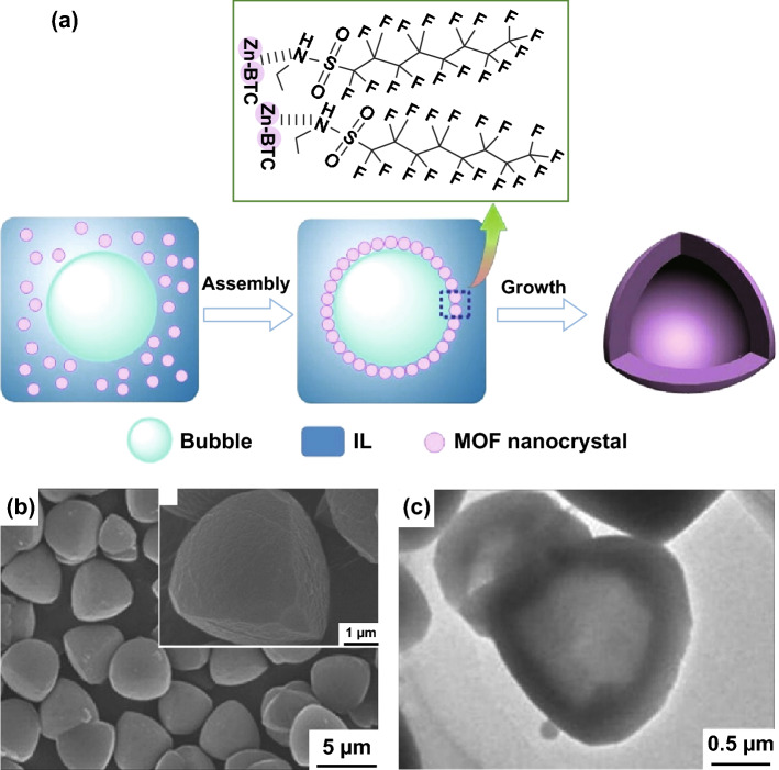
As an early demonstration of this synthetic strategy, Peng et al. [113] described a CO2–ionic liquid interfacial templating route for the synthesis of hollow Zn-based MOF polyhedra. By varying the pressure of gaseous CO2 from 10 to 63 bar in a solution of N-ethyl perfluorooctylsulfonamide/N,N,N′,N′-tetramethylguanidinium trifluoroacetate (N-EtFOSA/TMGT), tetrahedron-like particles were formed as CO2 bubbles were generated (Fig. 15a). It was seen that at high pressure, the MOF tetrahedroids possessed a hollow structure with inner cores evidenced by SEM (Fig. 15b), TEM (Fig. 15c), and gas sorption. The formation of this structure was explained by the selective assembly of metal nodes and organic linkers at the bubble interfaces during the crystallisation. This MOF was then tested in the reaction of propylene oxide and CO2 to produce propylene carbonate, indicating an increase in conversion from 20 to 97% with the presence of the hollow structure.
Fig. 15.
a Schematic illustration for the formation of hollow Zn–BTC tetrahedroids via a CO2–IL interfacial templating route. b SEM and c TEM images of the hollow tetrahedron-like Zn–BTC microparticles. The N-EtFOSA concentration is 2.0 wt% based on IL and the CO2 pressure is 6.3 MPa.
Reprinted with permission from Ref. [113]. Copyright 2014 Elsevier Inc
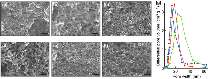
At the same time, Peng et al. [114] also reported a method using CO2 to form an expanded solvent to synthesise HKUST-1 (Fig. 16a–f). It is noticeable that large mesopores (up to 30 nm) with pore wall diameters of around 10 nm could be formed within this MOF by increasing pressure to 66 bar at 30 °C for 3 h (Fig. 16g), resulting in improved performance in catalysed reactions with benzyl alcohol oxidation. The mesocellular formation in CO2-expanded liquids was explained by the assembly of HKUST-1 nanosized framework building blocks in expanded liquid volumes at CO2 pressure. While the formation of larger mesopores was favoured by higher CO2 pressures, this study was limited to introducing CO2 at 66 bar and 30 °C; the maximum pore sizes witnessed were ~ 30 nm. It can be anticipated that these mesopores need to be further enlarged in some cases to obtain macropores to more significantly enhance the transportation of reactants, intermediates, and products in heterogeneous catalysis applications.
Fig. 16.
a–f SEM images of HKUST-1 synthesised in CO2-expanded DMF. a, b 2.0; c, d 4.5; e, f 6.6 MPa. Scale bars, 150, 50, 500, 150, 500, and 150 nm for a–f, respectively. g The mesopore size distribution curves for the Cu3(BTC)2 synthesised in CO2-expanded DMF at 2.0 MPa (blue curves), 4.5 MPa (red curves) and 6.6 MPa (green curves).
Reprinted with permission from Peng et al. [114]. Copyright CC BY-NC-SA 4.0. (Color figure online)
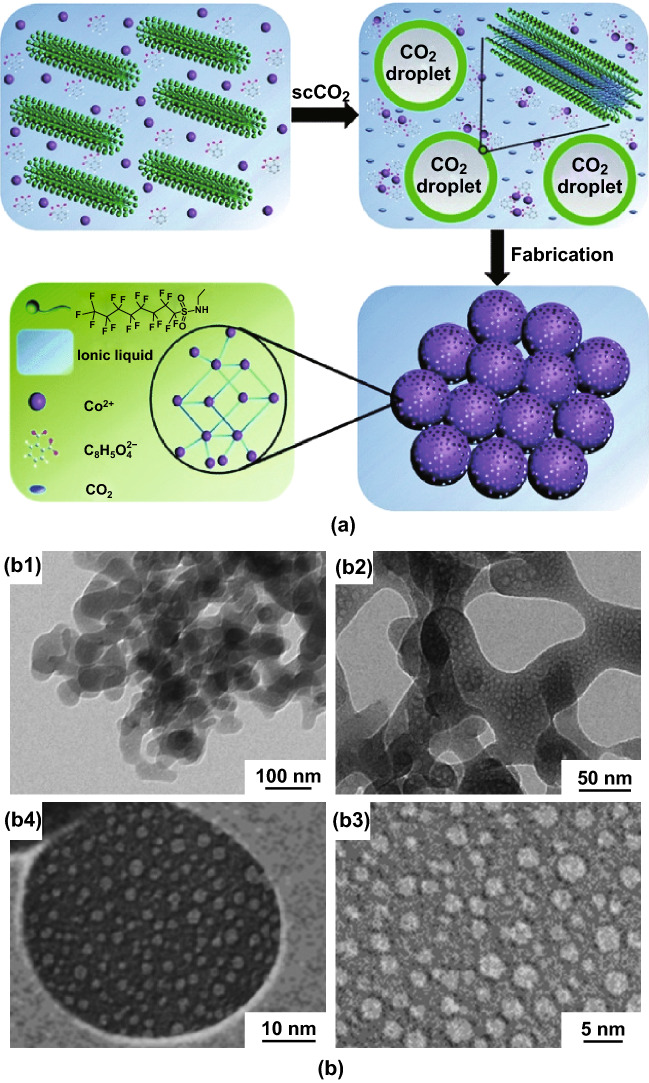
Utilisation of scCO2 in binary solvent systems comprising an ionic liquid (IL) was also reported for the synthesis of mesoporous zinc and cobalt MOFs (Fig. 17a) [115, 116]. In these studies, scCO2 not only established the pattern of the MOF nanospheres but also swelled the IL micelles to form long-range ordered mesopores which could be tuned easily by changing the CO2 pressure. Remarkably, in the case of Co-MOF [115], a series of interconnected macropores could also be seen with a worm-like morphology (Fig. 17b). The resulting Co-MOF was shown to possess high specific capacitance values (230.5 F g−1 at 0.5 A g−1). Note that these MOF syntheses were investigated at supercritical conditions of CO2 (160 bar, 80 °C) and for extended reaction times (48 h) which differ from conditions chosen in Peng’s research introduced previously. The extreme reaction conditions in CO2 have also been employed in the synthesis of 1D, 2D, and 3D MOFs by reactive crystallisation in the absence of or using lower volumes of solvents [117–119].
Fig. 17.
a Schematic illustration for the formation of the mesoporous Co-MOF in an IL/SC CO2/surfactant emulsion system. b TEM images of the Co-MOF synthesised in an IL/SC CO2/surfactant emulsion system at 16 MPa and 80 °C for 48 h.
Reprinted with permission from Ref. [115]. Copyright 2015 Royal Society of Chemistry
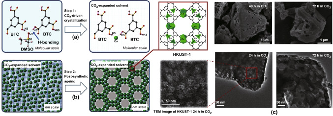
By tuning the conditions used in previous studies, Doan et al. [120] demonstrated the synthesis of HKUST-1 using scCO2 as a pressure-tuneable antisolvent to induce MOF crystallisation from the resulting expanded liquid phase (Fig. 18a). Interestingly, this methodology allowed control over nucleation and growth kinetics and also introduced a range of larger macropores into these typically microporous materials leading to so-called hierarchical porous materials (Fig. 18b). The ability to control the expansion of the solvent by control of the density of CO2 permits access to new structures and material morphologies not accessible by traditional methods. SEM and TEM images of the materials showed that crystallites were of the order of ~ 100 nm to microns in size, with interconnected macropores ranging from ~ 50 to 200 nm in diameter (Fig. 18c). A view cell experiment (allowing direct observation of the reactants under high pressure scCO2) showed that HKUST-1 could be formed within a few minutes rather than the 18 h required for the conventional synthesis [121]. In addition, due to the expansion in volume with CO2 pressure, the amount of the methanol antisolvent required was greatly reduced in comparison with the conventional synthesis.
Fig. 18.
Schematic illustration for a HKUST-1 crystallisation and b meso/macropore formation in the CO2-expanded solvent. c SEM images (top) and TEM images (bottom) of HKUST-1 synthesised using scCO2 at 75 bar, 40 °C for more than 24 h, showing introduction of interconnected macropores.
Reprinted with permission from Doan et al. [120]. Copyright CC BY-NC-SA 4.0
The latest research demonstrates that MOFs with macropores can be synthesised using scCO2. These findings suggest an intelligent method to obtain an open macroporous structure without using templates. It is anticipated that this process may be applicable to other MOF systems. Note that in the case of HKUST-1 metal–ligand coordination forces between Cu2+ and BTC3− in DMSO dominated the MOF aggregation process, resulting in a precursor solution [122]. It was found that the nucleation was only trigged when the introduction of CO2 and a small amount of methanol served to disrupt the H-bonding in the stock solution. Due to critical conditions of CO2 applied in this method (Tc and Pc of CO2 are 31.1 °C and 73.9 bar, respectively [123]), a high pressure reactor needed to be employed. Also, low temperature synthesis at 40 °C was found to be more favourable, which is not easy to achieve for most MOFs. Another challenge in this synthetic strategy is carrying out the experiment in in situ characterisation to understand the mechanism of the macropore formation during CO2 pressurisation.
3D Printing Method
The formation of macropores in MOFs by the acid etching and scCO2 methods has been shown to be beneficial for catalytic applications, but, with the exception of the MOF aerogels, most still result in MOF materials consisting of small crystallites, rather than controllable monolithic structures. As discussed in the preceding sections, a key barrier to the implementation of MOFs in industry is their lack of processability owing to their general insolubility and inherently powdered form. While a variety of methods have been attempted to transform MOF powders into appropriate monolithic forms, such as pressing powders into pellets [124], melting them to form glasses [125–127], or forming MOF coatings on monolithic supports (such as those mentioned in Sect. 2.1) [128], typically such techniques result in reduced MOF surface area.
Over the past few decades, 3D printing, also known as additive manufacture or robocasting technology, has been developed and applied successfully to fabricate monoliths with controlled 3D shapes by careful placement of material in space. Currently, printing methods are not limited to utilising inks comprised of plastics for art exhibitions and may also employ inks comprised of ceramics, metals, graphene additives, and even stimuli-responsive hydrogel composites [129] for prototyping and industrial applications [130–132]. Recently, there have been a growing number of research papers on developing tailored porous biomedical scaffolds [133], membranes [134–136], carbons [137], zeolites [138–140], aminosilicate adsorbents [141], and heterogeneous catalytic systems [142] by taking advantage of this technique.
In comparison with other processing techniques for making microporous MOFs such as solvothermal and microemulsions, 3D printing promises multiple advantages such as high reproducibility of complex geometries, low cost, scalability, and efficiency. Furthermore, with regards to MOFs specifically, the printing of a MOF composite would represent major advantages over alternative methods of monolith formation, which generally involve the deposition of MOFs onto non-flexible substrates like metals and require complicated techniques for precise MOF positioning [143, 144]. Additionally, a further benefit is the formation of a printed monolith has potential to enable additional porosity to be implemented depending on the additives employed in the ink. Hence, 3D printed monoliths not only offer an implementable contact medium for MOFs, but also enable an increased pore size distribution to be attained compared to parent MOF powders. In addition, polymers with a variety of unique attributes, such as softness, thermal and chemical stability, and optoelectrical properties, can be integrated with MOFs to make hybrids with sophisticated architectures [145]. With numerous potential applications, 3D-printed MOFs have been prepared successfully, though only recently, and therefore have been studied to only a limited extent.
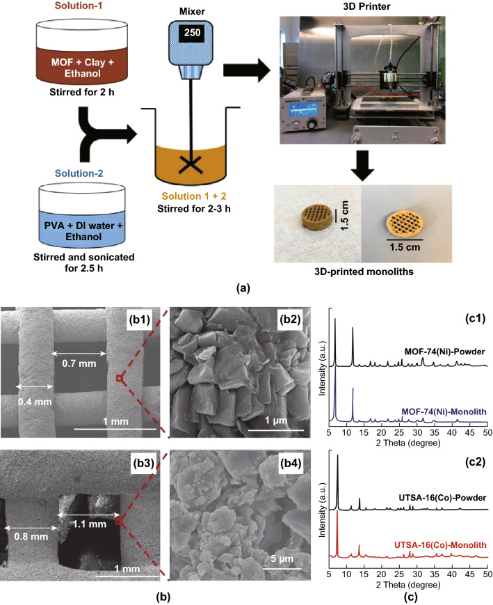
The first report in which MOF-based inks were developed and printed to give monoliths was described by Thakka et al. [146] and employed MOF-74(Ni) and UTSA-16(Co). In this study, pre-prepared MOF powders and bentonite clay (as a binder and rheological modifier) were dissolved in ethanol to obtain a homogeneous solution. This solution was then combined with a mixture of polyvinyl alcohol (PVA) and deionised water to form an extrudable paste, before loading into a 3D-printer to create macroscopic MOF-based objects with desired shapes, as illustrated in Fig. 19a. The obtained 3D-printed MOF monoliths (at 80 and 85 wt% loadings) retained the physical properties and mechanical integrity of their powder counterparts and also displayed crystallinity akin to their parent MOF crystal structures. While physical properties were retained, the surface area of the 3D-printed MOF composites was reduced by a maximum of 38% (from 1180 to 737 m2 g−1), owing to the inclusion of bentonite clay and PVA additives. The key challenge underlined by the work of Thakka et al. was the effect of ink rheology on the resulting printed structures, the cross-sectional areas of which are displayed in Fig. 19. Differences in wall thicknesses and channel sizes were attributed to the viscosity of the prepared MOF pastes, with the less viscous UTSA-16(Co) paste resulting in the expansion of layers on deposition. Nevertheless, the printed MOF monoliths displayed CO2 sorption capacities similar to their MOF powder counterparts with stable performance and faster adsorption kinetics than those of the corresponding powder (by 15 min).
Fig. 19.
a Schematic of the 3D-printed MOF monolith preparation procedure. b SEM images of 3D-printed MOF-74 (Ni) (b1 and b2) and 3D-printed UTSA-16 (Co) (b3 and b4), showing uniform distribution of MOF crystals and with large voids. c PXRD patterns of 3D-printed MOF-74 (Ni) (c1) and 3D-printed UTSA-16 (Co) (c2) with their powder counterparts, showing crystallinity retained for both MOF-74 (Ni) and UTSA-16 (Co) MOFs after they were extruded into the monolith form.
Reprinted with permission from Ref. [146]. Copyright 2017 American Chemical Society
According to Semino et al. [147], the general method developed by Thakka et al. for the production of hierarchical MOF monoliths is likely governed by the polymer it is embedded in: firstly by the partial blocking of MOF pores by flexible polymers (giving smaller pore sizes) and secondly by the formation of voids within the polymer matrix itself. The influence of polymer characteristics on the fabrication of hierarchical MOF monoliths by 3D printing was in fact investigated by Evans et al. in 2018 [147]. In this study, high loadings of powdered ZIF-8 (up to 50 wt%) were incorporated into a matrix of either polylactic acid (PLA) or thermoplastic polyurethane, representing rigid and flexible polymer matrices, respectively, to produce a filament feedstock for 3D printing. It was revealed that the rigidity of the PLA chains limited their reorganisation around ZIF-8 crystals during extrusion, resulting in various void sizes (micro-, meso-, and macro-voids) and hence giving a hierarchical MOF monolith with preserved MOF crystallinity. Unfortunately, employment of the flexible polymer matrix resulted in almost complete pore occlusion, as concluded from the low specific surface area of the monolith (68 m2 g−1 at 50% MOF loading).
Recently, Young et al. [148] highlighted a practical solution to the problem of pore occlusion in MOF composite monoliths by 3D-printing UiO-66 in combination with a mixture of flexible acrylates, which exhibited low thermal stability (< 100 °C). As expected, the printed UiO-66 monoliths were non-porous (owing to blockage by flexible acrylate chains); however, on heating to 100 °C, the polymer matrix degraded to recover porosity and reveal UiO-66 sites. Interestingly, although the treated composite displayed physisorption behaviour characteristic of microporous UiO-66, the presence of small mesopores was also identified. This work, carried out by Young et al., promises a method to embed MOFs within 3D printed monoliths and later exposes crystals as required for production of structures with hierarchical porosity. Furthermore, UiO-66 was found to behave as a rheological modifier itself, avoiding the need for additives such as the bentonite clay employed in earlier studies.
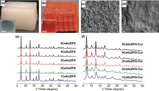
While the most commonly employed methods to prepare printable MOF inks combine synthesised MOFs and additives (such as binders and plasticisers) in ethanol, a novel one-pot room temperature approach using water as a solvent was carried out by Sultan et al. [149]. The printable ink was formulated by in situ growth of ZIF-8 and MIL-100(Fe) MOFs onto anionic 2,2,6,6-tetramethylpiperidine-1-oxylradical-mediated oxidised cellulose nanofibers (TOCNFs) prior to combination with a sodium alginate binder and calcium chloride crosslinker. Introducing MOFs into cellulose resulted in increased pore volume and surface area of the composite material compared to unmodified TOCNF. In contrast, the cellulose (with high aspect ratio, negative zeta potential, and good mechanical performance) provided benefits to MOFs by offering high printability and versatility of the hybrid inks. The printed scaffolds (Fig. 20a–d) possessed a large pore size (1 mm), useful for drug delivery applications, as the large pores would aid in infiltration of biological fluids into the support. In addition, the 3D-printed composite was found to be stimuli responsive (pH dependent) regarding the release of curcumin and methylene blue, indicating that the printed MOF monoliths produced using a simple and inexpensive printer could potentially be used in biomedical applications.
Fig. 20.
3D printed scaffolds: a 4CelloZIF8 and b 4CelloZIF8-Cur. Insets are images representing the pores, with the scale bar representing 0.5 mm. SEM images of c scaffold 4CelloZIF8 and d scaffold 4CelloZIF8-Cur. Scale bar = 1 µm. e PXRD patterns of CelloZIF8 hybrids using different ZIF-8 and f different ZIF-8 loadings while keeping Hmim:Zn to 35:1 and curcumin to 30 mg, showing that the crystallinity and the framework are maintained with different curcumin and Zn loadings.
Reprinted with permission from Ref. [149]. Copyright 2019 Wiley-VCH Verlag GmbH & Co. KGaA, Weinheim
Recent developments in the fabrication of 3D-printed MOFs have been successful in both providing a monolith suited for practical applications and adding hierarchical porosity into MOF-based materials. Although 3D printing of MOF monoliths has predominantly required high processing temperatures (up to 230 °C) or ultraviolet curing [150, 151], the work described by Sultan et al. demonstrated the feasibility of room temperature synthesis. However, it should be noted that this technique may not be suited to a variety of MOFs which are unstable in air, since the layer-by-layer printing process may necessitate air exposure for extended periods (15–120 h). For example, Kreider et al. [152] observed the degradation of water-sensitive MOF-5 during blending of the printable ink with the MOF powder and attributed this to ambient humidity. Interestingly though, irrespective of the observed MOF degradation, the resulting monolith was capable of adsorbing more H2 than the pure polymer counterpart, demonstrating the viability for H2 storage using 3D printed MOFs even in humid conditions.
Overall, the ability to tailor both the MOF and binding matrix could render extensive applications viable, from providing photonic platforms to biomedical testing and catalysis. While the precise placement of materials in 3D printing renders more complex macroscale structures achievable, it should be noted that fine control on the micron–nanoscale could be challenging in terms of accurately controlling the size of macropores which form inherently during ink deposition. However, as 3D printing methods become more established, it is anticipated that finer control over macropore sizes will be achievable. Finally, since significant research attention has taken steps towards employing MOFs in biomolecule encapsulation for controlled drug delivery and in biological applications, where macroporosity would be beneficial for facilitating mass transfer of biological fluids, it may be useful to consider the biodegradability of MOFs in low pH environments [153, 154]. To this end, future work could explore the development of ink matrices which could protect embedded MOFs from such degradation.
Conclusions
In this review, a range of fabrication methods for creating hierarchical MOF pore structures with additional macropores were discussed. Introduction of macroporosity has been demonstrated to lead to improvements in mass transfer and catalytic activity, and reductions in pressure drop over traditional powdered or nanocrystalline materials. These macropores can also improve molecular accessibility of reagents to the microporous cavities, which accommodate important functional groups or active sites, enhancing the catalytic performance of the materials. The advantages of macropores in catalytic applications have been well demonstrated for zeolites and metal oxides. For MOFs as microporous crystallites (which are purposely designed to possess high surface areas), introducing additional meso- and macropores to form hierarchical structures without compromising the micropores and the crystallinity, which give them high surface areas, is becoming the subject of much research. While mesopores can be created via numerous methods such as ligand exchange and use of surfactants, further expanding these to the macropore regime remains a challenge due to the ligand size limitation and the post-synthetic activation methods needed to obtain accessible pores.
As shown here, the main techniques reported for fabrication of macroporous materials can be described using four general approaches: use of structural templating, defect formation, use of CO2, and 3D printing. Templating stands out as the most popular route towards obtaining macroporous MOFs with numerous studies reported so far, due to the ease of structural control and the ease with which this method can be adapted for use with a range of MOFs. Deposition of MOFs onto hard macroporous templates and the formation of MOF composites via direct synthesis onto a porous template often do not require significant deviation from the synthetic conditions identified for the MOF itself and may offer an additional advantage in improving mechanical and thermochemical stability and providing immobilisation of nanocrystalline MOF materials. This may improve the outlook for MOFs to be used in industrial catalysis, for example, in alkylation and fluid catalytic cracking in oil refining processes involving bulky hydrocarbons, where harsh conditions require higher catalyst stability. In addition, the use of a hard template means that the active MOF material may only constitute a small proportion of the overall composite by weight, which may be advantageous in the case of more expensive MOF materials. In post-treatment synthetic methods, pre-formed MOFs can be immobilised on macroporous templates such as foams and sponges using dip-coating methods to form the composites. The stability of the MOFs used in this method remains a major challenge due to a long exposure time to the high humidity conditions during the immobilisation process, though this may be addressed through careful choice of solvents. In addition, in these macroporous composite structures, the MOF materials must be suitably bonded to the surface (e.g. via functionalisation of the template surface) to avoid being washed off over time.
If, rather than rigid composites, flexible composites or pure macroporous MOF structures are required, soft macroporous templates such as polymers, emulsions, or gels can be used. Polymer templates can allow for more pliable macroporous structures, while the use of emulsions or gels may allow for easier removal after templating. Use of sacrificial soft templates can result in macroporous stand-alone aerogel monoliths which can lead to easier and safer materials handling for particular applications; however, careful template removal is required to avoid incomplete removal (which could lead to loss of porosity) or collapse of pore networks.
Defect formation can be implemented via direct synthesis using linker modulation techniques or post-synthetic acid etching of prepared MOFs in low pH environments. The former has been widely reported for synthesis of mesoporous MOFs with defects as active adsorption and reaction sites for enhanced catalytic activity and gas storage, with linker modulation now being explored for introduction of larger macroporous voids. Defect formation via acid etching can overcome the limitation of the need for extended ligands and can potentially create macropores via size-selective diffusion processes. In fact, various etching agents such as hydroquinone, boric acid, and phosphoric acid have been studied so far to synthesise some impressive macroporous MOF crystal structures. While this method remains challenging due to the instability of most MOFs under acidic conditions, there have been promising recent developments, such as the discovery that careful selection of solvents can allow large geometrical pores within HKUST to be achieved by acid etching and that the use of synergistic etching to protect surfaces can be used to control etching. These examples indicate that with further investigation of the synthetic conditions and further understanding of the etching mechanisms, this simple approach to the formation of such macropores in MOF crystallites may be more widely applied.
Utilising supercritical or compressed CO2 in MOF preparation can address some key challenges noted in previous methods including pore collapse during solvent removal steps when using soft structural templating. In fact, this method is well known in MOF synthesis and post-synthetic treatment and has showed some promising results in creating open macroporous aerogel structures. Further adapting the synthetic conditions (e.g. longer reaction times and higher pressures), the use of scCO2 routes was shown to be able to form additional macropores in the direct synthesis of MOFs. In HKUST-1 synthesis, this method was also demonstrated to quickly trigger the reaction with a lowered amount of solvent, and as an added advantage, due to the insolubility of scCO2 in stock solutions, the multiple purification steps required in conventional synthetic methods could be curtailed. Particle sizes and porosity of this MOF can be tuneable via tight control over etching time. This route offers substantial benefits in HKUST-1 preparation compared to conventional solvothermal method. However, the mechanisms of the macroporous HKUST-1 formation need to be fully understood, before generalising this strategy to other MOF systems.
Finally, 3D printing is a very new fabrication technique which shows promise for generalised use in MOF preparation, allowing a very high MOF loading to be incorporated into porous printed structures (~ 85 wt%). The high reproducibility, fabrication of complex geometries, and controlled pore structures of these MOFs have potential to open up new applications for MOF materials in biomedical fields. This method, however, relies on the ability to incorporate MOFs and MOF precursors into inks capable of being printed into stable structures without compromising on the nanoscale structure of the MOF. Enabling higher resolution (sub-mm) printing is also an area for future development, to enable greater control over the macrostructure, for example in biomedical applications such as tailored drug delivery or the size-selective diffusion of proteins to oxidation sites within MOFs facilitates biocatalysis.
As shown by many of the studies mentioned in this review, macroporous MOF structures can show enhanced performance in adsorptive and catalytic applications due to the improved mass transfer and molecular accessibility. It can be predicted that more research will be carried out to produce more useful composites of functional MOFs coordinated with macroporous substrates using reproducible and sustainable synthetic approaches. The range of fabrication approaches presented here indicates the vast variety of different macroporous structures that can be achieved using functional MOF materials. The ability to include structural macroporosity should help to accelerate the practical application of MOFs in such varied fields as large molecule adsorption and separation, water purification, bulky drug delivery, and heterogeneous catalysis. Further development of this toolbox will surely give material scientists greater flexibility in tailoring the porosity and structure of their MOF materials towards particular functions.
Acknowledgements
This work was financially supported by the Vietnamese Ministry of Education and Training and the UK Engineering and Physical Sciences Research Council (EP/R01650X/1 and EP/L016028/1).
Contributor Information
Huan V. Doan, Email: huan.doan@bristol.ac.uk
Valeska P. Ting, Email: v.ting@bristol.ac.uk
References
- 1.Nugent P, Giannopoulou EG, Burd SD, Elemento O, Giannopoulou EG, et al. Porous materials with optimal adsorption thermodynamics and kinetics for CO2 separation. Nature. 2013;495:80–84. doi: 10.1038/nature11893. [DOI] [PubMed] [Google Scholar]
- 2.Jiang DE, Cooper VR, Dai S. Porous graphene as the ultimate membrane for gas separation. Nano Lett. 2009;9:4019–4024. doi: 10.1021/nl9021946. [DOI] [PubMed] [Google Scholar]
- 3.Steel KM, Koros WJ. Investigation of porosity of carbon materials and related effects on gas separation properties. Carbon. 2003;41:253–266. doi: 10.1016/S0008-6223(02)00309-3. [DOI] [Google Scholar]
- 4.Wang QM, Shen D, Bülow M, Lau ML, Deng S, Fitch FR, Lemcoff NO, Semanscin J. Metallo-organic molecular sieve for gas separation and purification. Microporous Mesoporous Mater. 2002;55:217–230. doi: 10.1016/S1387-1811(02)00405-5. [DOI] [Google Scholar]
- 5.Rashidi S, Esfahani JA, Karimi N. Porous materials in building energy technologies—a review of the applications, modelling and experiments. Renew. Sustain. Energy Rev. 2018;91:229–247. doi: 10.1016/j.rser.2018.03.092. [DOI] [Google Scholar]
- 6.Vix-Guterl C, Frackowiak E, Jurewicz K, Friebe M, Parmentier J, Béguin F. Electrochemical energy storage in ordered porous carbon materials. Carbon. 2005;43:1293–1302. doi: 10.1016/j.carbon.2004.12.028. [DOI] [Google Scholar]
- 7.Li Y, Fu ZY, Su BL. Hierarchically structured porous materials for energy conversion and storage. Adv. Funct. Mater. 2012;22:4634. doi: 10.1002/adfm.201200591. [DOI] [Google Scholar]
- 8.Han S, Wu D, Li S, Zhang F, Feng X. Porous graphene materials for advanced electrochemical energy storage and conversion devices. Adv. Mater. 2014;26:849–864. doi: 10.1002/adma.201303115. [DOI] [PubMed] [Google Scholar]
- 9.Wang S. Ordered mesoporous materials for drug delivery. Microporous Mesoporous Mater. 2009;117:1–9. doi: 10.1016/j.micromeso.2008.07.002. [DOI] [Google Scholar]
- 10.Horcajada P, Serre C, Vallet-Regí M, Sebban M, Taulelle F, Férey G. Metal–organic frameworks as efficient materials for drug delivery. Angew. Chem. Int. Ed. 2006;45:5974–5978. doi: 10.1002/anie.200601878. [DOI] [PubMed] [Google Scholar]
- 11.Horcajada P, Chalati T, Serre C, Gillet B, Sebrie C, et al. Porous metal–organic-framework nanoscale carriers as a potential platform for drug deliveryand imaging. Nat. Mater. 2010;9:172–178. doi: 10.1038/nmat2608. [DOI] [PubMed] [Google Scholar]
- 12.Horcajada P, Serre C, Maurin G, Ramsahye NA, Balas F, et al. Flexible porous metal–organic frameworks for a controlled drug delivery. J. Am. Chem. Soc. 2008;130:6774–6780. doi: 10.1021/ja710973k. [DOI] [PubMed] [Google Scholar]
- 13.Perego C, Millini R. Porous materials in catalysis: challenges for mesoporous materials. Chem. Soc. Rev. 2013;42:3956–3976. doi: 10.1039/c2cs35244c. [DOI] [PubMed] [Google Scholar]
- 14.Lee J, Farha OK, Roberts J, Scheidt KA, Nguyen ST, Hupp JT. Metal–organic framework materials as catalysts. Chem. Soc. Rev. 2009;38:1450–1459. doi: 10.1039/b807080f. [DOI] [PubMed] [Google Scholar]
- 15.Parlett CMA, Wilson K, Lee AF. Hierarchical porous materials: catalytic applications. Chem. Soc. Rev. 2013;42:3876–3893. doi: 10.1039/c2cs35378d. [DOI] [PubMed] [Google Scholar]
- 16.Taguchi A, Schüth F. Ordered mesoporous materials in catalysis. Microporous Mesoporous Mater. 2005;77:1–45. doi: 10.1016/j.micromeso.2004.06.030. [DOI] [Google Scholar]
- 17.J. Rouquerol, D. Avnir, C.W. Fairbridge, D.H. Everett, J.M. Haynes et al., Recommendations for the Characterization of Porous Solids (Technical Report) (1994)
- 18.Sing KSW. Reporting physisorption data for gas/solid systems with special reference to the determination of surface area and porosity (Recommendations 1984) Pure Appl. Chem. 2007;57:603–619. doi: 10.1351/pac198557040603. [DOI] [Google Scholar]
- 19.Schwieger W, Machoke AG, Weissenberger T, Inayat A, Selvam T, Klumpp M, Inayat A. Hierarchy concepts: classification and preparation strategies for zeolite containing materials with hierarchical porosity. Chem. Soc. Rev. 2016;45:3353–3376. doi: 10.1039/c5cs00599j. [DOI] [PubMed] [Google Scholar]
- 20.Betke U, Lieb A. Micro-macroporous composite materials—preparation techniques and selected applications: a review. Adv. Eng. Mater. 2018;20:1800252. doi: 10.1002/adem.201800252. [DOI] [Google Scholar]
- 21.Yang XY, Chen LH, Li Y, Rooke JC, Sanchez C, Su BL. Hierarchically porous materials: synthesis strategies and structure design. Chem. Soc. Rev. 2017;46:481–558. doi: 10.1039/c6cs00829a. [DOI] [PubMed] [Google Scholar]
- 22.Moghadam PZ, Li A, Wiggin SB, Tao A, Maloney AGP, et al. Development of a cambridge structural database subset: a collection of metal–organic frameworks for past, present, and future. Chem. Mater. 2017;29:2618–2625. doi: 10.1021/acs.chemmater.7b00441. [DOI] [Google Scholar]
- 23.Gómez-Gualdrón DA, Colón YJ, Zhang X, Wang TC, Chen YS, et al. Evaluating topologically diverse metal–organic frameworks for cryo-adsorbed hydrogen storage. Energy Environ. Sci. 2016;9:3279–3289. doi: 10.1039/c6ee02104b. [DOI] [Google Scholar]
- 24.Mason JA, Oktawiec J, Taylor MK, Hudson MR, Rodriguez J, et al. Methane storage in flexible metal–organic frameworks with intrinsic thermal management. Nature. 2015;527:357–361. doi: 10.1038/nature15732. [DOI] [PubMed] [Google Scholar]
- 25.Zou L, Zhou HC. Hydrogen storage in metal–organic frameworks. In: Chen YP, Bashir S, Liu J, editors. Nanostructured Materials for Next-Generation Energy Storage and Conversion. Berlin: Springer; 2017. [Google Scholar]
- 26.Holcroft JM, Hartlieb KJ, Moghadam PZ, Bell JG, Barin G, et al. Carbohydrate-mediated purification of petrochemicals. J. Am. Chem. Soc. 2015;137:5706–5719. doi: 10.1021/ja511878b. [DOI] [PubMed] [Google Scholar]
- 27.Li JR, Kuppler RJ, Zhou HC. Selective gas adsorption and separation in metal–organic frameworks. Chem. Soc. Rev. 2009;38:1477–1504. doi: 10.1039/b802426j. [DOI] [PubMed] [Google Scholar]
- 28.DeCoste JB, Peterson GW. Metal–organic frameworks for air purification of toxic chemicals. Chem. Rev. 2014;114:5695–5727. doi: 10.1021/cr4006473. [DOI] [PubMed] [Google Scholar]
- 29.Zhao X, Wang Y, Li DS, Bu X, Feng P. Metal–organic frameworks for separation. Adv. Mater. 2018;30:1705189. doi: 10.1002/adma.201705189. [DOI] [PubMed] [Google Scholar]
- 30.Liu J, Chen L, Cui H, Zhang J, Zhang L, Su CY. Applications of metal–organic frameworks in heterogeneous supramolecular catalysis. Chem. Soc. Rev. 2014;43:6011–6061. doi: 10.1039/c4cs00094c. [DOI] [PubMed] [Google Scholar]
- 31.Wu CD. Crystal engineering of metal–organic frameworks for heterogeneous catalysis. Select. Nanocatalysts Nanosci. 2011;110:271–298. doi: 10.1002/9783527635689.ch8. [DOI] [Google Scholar]
- 32.Sumida K, Rogow DL, Mason JA, McDonald TM, Bloch ED, et al. Carbon dioxide capture in metal–organic frameworks. Chem. Rev. 2012;112:724–781. doi: 10.1021/cr2003272. [DOI] [PubMed] [Google Scholar]
- 33.McDonald TM, Mason JA, Kong X, Bloch ED, Gygi D, et al. Cooperative insertion of CO2 in diamine-appended metal–organic frameworks. Nature. 2015;519:303–308. doi: 10.1038/nature14327. [DOI] [PubMed] [Google Scholar]
- 34.Yazaydin AÖ, Snurr RQ, Park TH, Koh K, Liu J, et al. Screening of metal–organic frameworks for carbon dioxide capture from flue gas using a combined experimental and modeling approach. J. Am. Chem. Soc. 2009;131:18198–18199. doi: 10.1021/ja9057234. [DOI] [PubMed] [Google Scholar]
- 35.Férey G. Hybrid porous solids: past, present, future. Chem. Soc. Rev. 2008;37:191–214. doi: 10.1039/b618320b. [DOI] [PubMed] [Google Scholar]
- 36.Sheberla D, Sun L, Blood-Forsythe MA, Er S, Wade CR, Brozek CK, Aspuru-Guzik A, Dincǎ M. High electrical conductivity in Ni3(2,3,6,7,10,11- hexaiminotriphenylene)2, a semiconducting metal–organic graphene analogue. J. Am. Chem. Soc. 2014;136:8859–8862. doi: 10.1021/ja502765n. [DOI] [PubMed] [Google Scholar]
- 37.Guan HY, LeBlanc RJ, Xie SY, Yue Y. Recent progress in the syntheses of mesoporous metal–organic framework materials. Coord. Chem. Rev. 2018;369:76–90. doi: 10.1016/j.ccr.2018.05.001. [DOI] [Google Scholar]
- 38.Liu D, Zou D, Zhu H, Zhang J. Mesoporous metal–organic frameworks: synthetic strategies and emerging applications. Small. 2018;14:1801454. doi: 10.1002/smll.201801454. [DOI] [PubMed] [Google Scholar]
- 39.Wang K, Zhang Y, Zhao J, Yan C, Wei Y, et al. Facile synthesis of hierarchical porous solid catalysts with acid-base bifunctional active sites for the conversion of cellulose to 5-hydroxymethylfurfural. New J. Chem. 2018;42:18084–18095. doi: 10.1039/c8nj03812k. [DOI] [Google Scholar]
- 40.Xiang Q, Yu J. Photocatalytic activity of hierarchical flower-like TiO2 superstructures with dominant 001 facets. Chin. J. Catal. 2011;32:525–531. doi: 10.1016/S1872-2067(10)60186-6. [DOI] [Google Scholar]
- 41.Xi G, Yue B, Cao J, Ye J. Fe3O4/WO3 Hierarchical core-shell structure: high-performance and recyclable visible-light photocatalysis. Chem. A Eur. J. 2011;17:5145–5154. doi: 10.1002/chem.201002229. [DOI] [PubMed] [Google Scholar]
- 42.Feng L, Yuan S, Li JL, Wang KY, Day GS, et al. Uncovering two principles of multivariate hierarchical metal–organic framework synthesis via retrosynthetic design. ACS Cent. Sci. 2018;4:1719–1726. doi: 10.1021/acscentsci.8b00722. [DOI] [PMC free article] [PubMed] [Google Scholar]
- 43.Brunauer S, Emmett PH, Teller E. Adsorption of gases in multimolecular layers. J. Am. Chem. Soc. 1938;60:309–319. doi: 10.1021/ja01269a023. [DOI] [Google Scholar]
- 44.Klobes P, Meyer K, Munro RG. Porosity and Specific Surface Area Measurements for Solid Materials. Washington: NIST Special Publications; 2006. [Google Scholar]
- 45.Barrett EP, Joyner LG, Halenda PP. The determination of pore volume and area distributions in porous substances. I. Computations from nitrogen isotherms. J. Am. Chem. Soc. 1951;73:373–380. doi: 10.1021/ja01145a126. [DOI] [Google Scholar]
- 46.Joyner LG, Barrett EP, Skold R. The determination of pore volume and area distributions in porous substances. II. Comparison between nitrogen isotherm and mercury porosimeter methods. J. Am. Chem. Soc. 1951;73:3155–3158. doi: 10.1021/ja01151a046. [DOI] [Google Scholar]
- 47.Feigin LA, Svergun DI. Structure Analysis by Small-Angle X-Ray and Neutron Scattering. Boston: Springer; 1987. [Google Scholar]
- 48.Rouquerol J, Baron GV, Denoyel R, Giesche H, Groen J, et al. The characterization of macroporous solids: an overview of the methodology. Microporous Mesoporous Mater. 2012;154:2–6. doi: 10.1016/j.micromeso.2011.09.031. [DOI] [Google Scholar]
- 49.Radlinski A, Mastalerz M, Hinde A, Hainbuchner M, Rauch H, et al. Application of SAXS and SANS in evaluation of porosity, pore size distribution and surface area of coal. Int. J. Coal Geol. 2004;59:245–271. doi: 10.1016/J.COAL.2004.03.002. [DOI] [Google Scholar]
- 50.Ting VP, Ramirez-Cuesta AJ, Bimbo N, Sharpe JE, Noguera-Diaz A, et al. Direct evidence for solid-like hydrogen in a nanoporous carbon hydrogen storage material at supercritical temperatures. ACS Nano. 2015;9:8249–8254. doi: 10.1021/acsnano.5b02623. [DOI] [PubMed] [Google Scholar]
- 51.Wang Y, De Carlo F, Mancini DC, McNulty I, Tieman B, et al. A high-throughput x-ray microtomography system at the advanced photon source. Rev. Sci. Instrum. 2001;72:2062. doi: 10.1063/1.1355270. [DOI] [Google Scholar]
- 52.Farha OK, Eryazici I, Jeong NC, Hauser BG, Wilmer CE, et al. Metal–organic framework materials with ultrahigh surface areas: Is the sky the limit? J. Am. Chem. Soc. 2012;134:15016–15021. doi: 10.1021/ja3055639. [DOI] [PubMed] [Google Scholar]
- 53.Matsuyama K. Supercritical fluid processing for metal–organic frameworks, porous coordination polymers, and covalent organic frameworks. J. Supercrit. Fluids. 2018;134:197–203. doi: 10.1016/j.supflu.2017.12.004. [DOI] [Google Scholar]
- 54.Taguchi A, Smätt JH, Lindén M. Carbon monoliths possessing a hierarchical, fully interconnected porosity. Adv. Mater. 2003;15:1209. doi: 10.1002/adma.200304848. [DOI] [Google Scholar]
- 55.Xue C, Tu B, Zhao D. Facile fabrication of hierarchically porous carbonaceous monoliths with ordered mesostructure via an organic self-assembly. Nano Res. 2009;2:242–253. doi: 10.1007/s12274-009-9022-y. [DOI] [Google Scholar]
- 56.Smått JH, Schunk S, Lindén M. Versatile double-templating synthesis route to silica monoliths exhibiting a multimodal hierarchical porosity. Chem. Mater. 2003;15:2354–2361. doi: 10.1021/cm0213422. [DOI] [Google Scholar]
- 57.Yang CM, Smått JH, Zibrowius B, Lindén M. Chemical removal of organic polymers from highly porous sol–gel-derived silica monoliths. New J. Chem. 2004;28:1520–1525. doi: 10.1039/b407639g. [DOI] [Google Scholar]
- 58.Nardes AM, Janssen RAJ, Kemerink M. A morphological model for the solvent-enhanced conductivity of PEDOT: PSS thin films. Adv. Funct. Mater. 2008;18:865–871. doi: 10.1002/adfm.200700796. [DOI] [Google Scholar]
- 59.Sandra F, Depardieu M, Mouline Z, Vignoles GL, Iwamoto Y, Miele P, Backov R, Bernard S. Polymer-derived silicoboron carbonitride foams for CO2 capture: from design to application as scaffolds for the in situ growth of metal–organic frameworks. Chem. A Eur. J. 2016;22:8346–8357. doi: 10.1002/chem.201600060. [DOI] [PubMed] [Google Scholar]
- 60.Ren J, Segakweng T, Langmi HW, North BC, Mathe M. Ni foam-immobilized MIL-101(Cr) nanocrystals toward system integration for hydrogen storage. J. Alloys Compd. 2015;645:S170–S173. doi: 10.1016/j.jallcom.2015.01.083. [DOI] [Google Scholar]
- 61.Granato T, Testa F, Olivo R. Catalytic activity of HKUST-1 coated on ceramic foam. Microporous Mesoporous Mater. 2012;153:236–246. doi: 10.1016/j.micromeso.2011.12.055. [DOI] [Google Scholar]
- 62.Xie Y, Song Y, Zhang Y, Xu L, Miao L, Peng C, Wang L. Cu metal–organic framework-derived Cu Nanospheres@Porous carbon/macroporous carbon for electrochemical sensing glucose. J. Alloys Compd. 2018;757:105–111. doi: 10.1016/j.jallcom.2018.05.064. [DOI] [Google Scholar]
- 63.Betke U, Proemmel S, Rannabauer S, Lieb A, Scheffler M, Scheffler F. Silane functionalized open-celled ceramic foams as support structure in metal organic framework composite materials. Microporous Mesoporous Mater. 2017;239:209–220. doi: 10.1016/j.micromeso.2016.10.011. [DOI] [Google Scholar]
- 64.Betke U, Proemmel S, Eggebrecht JG, Rannabauer S, Lieb A, Scheffler M, Scheffler F. Micro-macroporous composite materials: SiC ceramic foams functionalized with the metal organic framework HKUST-1. Chem.-Ing.-Tech. 2016;88(3):264–273. doi: 10.1002/cite.201500141. [DOI] [Google Scholar]
- 65.Betke U, Klaus M, Eggebrecht JG, Scheffler M, Lieb A. MOFs meet macropores: dynamic direct crystallization of the microporous aluminum isophthalate CAU-10 on reticulated open-cellular alumina foams. Microporous Mesoporous Mater. 2018;265:43–56. doi: 10.1016/j.micromeso.2018.01.020. [DOI] [Google Scholar]
- 66.Hu Y, Lian H, Zhou L, Li G. In situ solvothermal growth of metal–organic framework-5 supported on porous copper foam for noninvasive sampling of plant volatile sulfides. Anal. Chem. 2015;87:406–412. doi: 10.1021/ac502146c. [DOI] [PubMed] [Google Scholar]
- 67.Sun Y, Yang F, Wei Q, Wang N, Qin X, et al. Oriented nano-microstructure-assisted controllable fabrication of metal–organic framework membranes on nickel foam. Adv. Mater. 2016;28:2374. doi: 10.1002/adma.201505437. [DOI] [PubMed] [Google Scholar]
- 68.Wang H, Qu ZG, Zhang W, Zhang LQ. A multi-scale porous composite adsorbent with copper benzene-1,3,5-tricarboxylate coating on copper foam. RSC Adv. 2016;6:52888–52897. doi: 10.1039/c6ra08622e. [DOI] [Google Scholar]
- 69.Shen K, Zhang L, Chen X, Liu L, Zhang D, et al. Ordered macro-microporous metal–organic framework single crystals. Science. 2018;359:206–210. doi: 10.1126/science.aao3403. [DOI] [PubMed] [Google Scholar]
- 70.Duan C, Zhang H, Yang M, Li F, Yu Y, Xiao J, Xi H. Templated fabrication of hierarchically porous metal–organic frameworks and simulation of crystal growth. Nanoscale Adv. 2019;1:1062–1069. doi: 10.1039/c8na00262b. [DOI] [PMC free article] [PubMed] [Google Scholar]
- 71.Lin KYA, Chang HA. A zeolitic imidazole framework (ZIF)-sponge composite prepared via a surfactant-assisted dip-coating method. J. Mater. Chem. A. 2015;3:20060–20064. doi: 10.1039/c5ta04427h. [DOI] [Google Scholar]
- 72.Pinto ML, Dias S, Pires J. Composite MOF foams: the example of UiO-66/polyurethane. ACS Appl. Mater. Interfaces. 2013;5:2360–2363. doi: 10.1021/am303089g. [DOI] [PubMed] [Google Scholar]
- 73.Cao S, Gody G, Zhao W, Perrier S, Peng X, Ducati C, Zhao D, Cheetham AK. Hierarchical bicontinuous porosity in metal–organic frameworks templated from functional block co-oligomer micelles. Chem. Sci. 2013;4:3573–3577. doi: 10.1039/c3sc51336j. [DOI] [Google Scholar]
- 74.Bo S, Ren W, Lei C, Xie Y, Cai Y, et al. Flexible and porous cellulose aerogels/zeolitic imidazolate framework (ZIF-8) hybrids for adsorption removal of Cr(IV) from water. J. Solid State Chem. 2018;262:135–141. doi: 10.1016/j.jssc.2018.02.022. [DOI] [Google Scholar]
- 75.Ren W, Gao J, Lei C, Xie Y, Cai Y, Ni Q, Yao J. Recyclable metal–organic framework/cellulose aerogels for activating peroxymonosulfate to degrade organic pollutants. Chem. Eng. J. 2018;349:766–774. doi: 10.1016/j.cej.2018.05.143. [DOI] [Google Scholar]
- 76.Yuan Y, Yang D, Mei G, Hong X, Wu J, Zheng J, Pang J, Yan Z. Preparation of konjac glucomannan-based zeolitic imidazolate framework-8 composite aerogels with high adsorptive capacity of ciprofloxacin from water. Colloids Surf. A. 2018;544:187–195. doi: 10.1016/j.colsurfa.2018.01.042. [DOI] [Google Scholar]
- 77.Mao J, Ge M, Huang J, Lai Y, Lin C, Zhang K, Meng K, Tang Y. Constructing multifunctional MOF@rGO hydro-/aerogels by the self-assembly process for customized water remediation. J. Mater. Chem. A. 2017;5:11873–11881. doi: 10.1039/c7ta01343d. [DOI] [Google Scholar]
- 78.Huang N, Drake H, Li J, Pang J, Wang Y, et al. Flexible and hierarchical metal–organic framework composites for high-performance catalysis. Angew. Chem. Int. Ed. 2018;57:8916–8920. doi: 10.1002/anie.201803096. [DOI] [PubMed] [Google Scholar]
- 79.Moitra N, Fukumoto S, Reboul J, Sumida K, Zhu Y, et al. Mechanically stable, hierarchically porous Cu3(btc)2 (HKUST-1) monoliths via direct conversion of copper(ii) hydroxide-based monoliths. Chem. Commun. 2015;51:3511–3514. doi: 10.1039/c4cc09694k. [DOI] [PubMed] [Google Scholar]
- 80.Xu F, Xian S, Xia Q, Li Y, Li Z. Effect of textural properties on the adsorption and desorption of toluene on the metal–organic frameworks HKUST-1 and MIL-101. Adsorpt. Sci. Technol. 2013;31:325–339. doi: 10.1260/0263-6174.31.4.325. [DOI] [Google Scholar]
- 81.Ma FJ, Liu SX, Liang DD, Ren GJ, Wei F, Chen YG, Su ZM. Adsorption of volatile organic compounds in porous metal–organic frameworks functionalized by polyoxometalates. J. Solid State Chem. 2011;184:3034–3039. doi: 10.1016/j.jssc.2011.09.002. [DOI] [Google Scholar]
- 82.Kim JH, Lee SJ, Kim MB, Lee JJ, Lee CH. Sorption equilibrium and thermal regeneration of acetone and toluene vapors on an activated carbon. Ind. Eng. Chem. Res. 2007;46:4584–4594. doi: 10.1021/ie0609362. [DOI] [Google Scholar]
- 83.Huang CY, Song M, Gu ZY, Wang HF, Yan XP. Probing the adsorption characteristic of metal–organic framework MIL-101 for volatile organic compounds by quartz crystal microbalance. Environ. Sci. Technol. 2011;45:4490–4496. doi: 10.1021/es200256q. [DOI] [PubMed] [Google Scholar]
- 84.Lu Y. Microporous silica prepared by organic templating: relationship between the molecular template and pore structure. Chem. Mater. 1999;11:1223–1229. doi: 10.1021/cm980517y. [DOI] [Google Scholar]
- 85.Hitz S, Prins R. Influence of template extraction on structure, activity, and stability of MCM-41 catalysts. J. Catal. 1997;168:194–206. doi: 10.1006/jcat.1997.1659. [DOI] [Google Scholar]
- 86.Pai RA, Humayun R, Schulberg MT, Sengupta A, Sun JN, Watkins JJ. Mesoporous silicates prepared using preorganized templates in supercritical fluids. Science. 2004;303:507–510. doi: 10.1126/science.1092627. [DOI] [PubMed] [Google Scholar]
- 87.Kepert CJ, Rosseinsky MJ. Zeolite-like crystal structure of an empty microporous molecular framework. Chem. Commun. 1999;4:375–376. doi: 10.1039/a809746a. [DOI] [Google Scholar]
- 88.Yuan S, Zou L, Qin JS, Li J, Huang L, et al. Construction of hierarchically porous metal–organic frameworks through linker labilization. Nat. Commun. 2017;8:15356. doi: 10.1038/ncomms15356. [DOI] [PMC free article] [PubMed] [Google Scholar]
- 89.Kim SY, Kim AR, Yoon JW, Kim HJ, Bae YS. Creation of mesoporous defects in a microporous metal–organic framework by an acetic acid-fragmented linker co-assembly and its remarkable effects on methane uptake. Chem. Eng. J. 2018;335:94–100. doi: 10.1016/j.cej.2017.10.078. [DOI] [Google Scholar]
- 90.Huang H, Li JR, Wang K, Han T, Tong M, et al. An in situ self-assembly template strategy for the preparation of hierarchical-pore metal–organic frameworks. Nat. Commun. 2015;6:8847. doi: 10.1038/ncomms9847. [DOI] [PMC free article] [PubMed] [Google Scholar]
- 91.Qiu LG, Xu T, Li ZQ, Wang W, Wu Y, Jiang X, Tian XY, De Zhang L. Hierarchically micro- and mesoporous metal–organic frameworks with tunable porosity. Angew. Chem. Int. Ed. 2008;47:9487–9491. doi: 10.1002/anie.200803640. [DOI] [PubMed] [Google Scholar]
- 92.Choi KM, Jeon HJ, Kang JK, Yaghi OM. Heterogeneity within order in crystals of a porous metal–organic framework. J. Am. Chem. Soc. 2011;133:11920–11923. doi: 10.1021/ja204818q. [DOI] [PubMed] [Google Scholar]
- 93.Cai G, Jiang HL. A modulator-induced defect-formation strategy to hierarchically porous metal–organic frameworks with high stability. Angew. Chem. Int. Ed. 2017;56:563–567. doi: 10.1002/anie.201610914. [DOI] [PubMed] [Google Scholar]
- 94.Koo J, Hwang IC, Yu X, Saha S, Kim Y, Kim K. Hollowing out MOFs: hierarchical micro- and mesoporous MOFs with tailorable porosity via selective acid etching. Chem. Sci. 2017;8:6799–6803. doi: 10.1039/c7sc02886e. [DOI] [PMC free article] [PubMed] [Google Scholar]
- 95.Ahmed A, Hodgson N, Barrow M, Clowes R, Robertson CM, et al. Macroporous metal–organic framework microparticles with improved liquid phase separation. J. Mater. Chem. A. 2014;2:9085–9090. doi: 10.1039/c4ta00138a. [DOI] [Google Scholar]
- 96.H.V. Doan, A. Sartbaeva, J.-C. Eloi, S. Davis, V.P. Ting, Defective hierarchical porous copper-based metal–organic frameworks synthesised via facile acid etching strategy. ArXiv preprint (2019). https://arxiv.org/abs/1904.10524v1 [DOI] [PMC free article] [PubMed]
- 97.Vermoortele F, Bueken B, Le Bars G, Van De Voorde B, Vandichel M, et al. Synthesis modulation as a tool to increase the catalytic activity of metal–organic frameworks: the unique case of UiO-66(Zr) J. Am. Chem. Soc. 2013;135:11465–11468. doi: 10.1021/ja405078u. [DOI] [PubMed] [Google Scholar]
- 98.Hu M, Ju Y, Liang K, Suma T, Cui J, Caruso F. Void engineering in metal–organic frameworks via synergistic etching and surface functionalization. Adv. Funct. Mater. 2016;26:5827–5834. doi: 10.1002/adfm.201601193. [DOI] [Google Scholar]
- 99.Yoo Y, Jeong HK. Generation of covalently functionalized hierarchical IRMOF-3 by post-synthetic modification. Chem. Eng. J. 2012;181–182:740–745. doi: 10.1016/j.cej.2011.11.048. [DOI] [Google Scholar]
- 100.Liu C, Zhang B, Zhang J, Peng L, Kang X, et al. Gas promotes the crystallization of nano-sized metal–organic frameworks in ionic liquid. Chem. Commun. 2015;51:11445–114488. doi: 10.1039/c5cc02503f. [DOI] [PubMed] [Google Scholar]
- 101.López-Periago A, López-Domínguez P, Barrio JP, Tobias G, Domingo C. Binary supercritical CO2 solvent mixtures for the synthesis of 3D metal–organic frameworks. Microporous Mesoporous Mater. 2016;234:155–161. doi: 10.1016/j.micromeso.2016.07.014. [DOI] [Google Scholar]
- 102.Portolés-Gil N, Lanza A, Aliaga-Alcalde N, Ayllón JA, Gemmi M, et al. Crystalline curcumin bioMOF obtained by precipitation in supercritical CO2 and structural determination by electron diffraction tomography. ACS Sustain. Chem. Eng. 2018;6:12309–12319. doi: 10.1021/acssuschemeng.8b02738. [DOI] [Google Scholar]
- 103.Weidner E. Impregnation via supercritical CO2—what we know and what we need to know. J. Supercrit. Fluids. 2018;134:220–227. doi: 10.1016/j.supflu.2017.12.024. [DOI] [Google Scholar]
- 104.Zhao Y, Zhang J, Song J, Li J, Liu J, Wu T, Zhang P, Han B. Ru nanoparticles immobilized on metal–organic framework nanorods by supercritical CO2-methanol solution: highly efficient catalyst. Green Chem. 2011;13:2078–2082. doi: 10.1039/c1gc15340d. [DOI] [Google Scholar]
- 105.Cooper AI, Rosseinsky MJ. Metal–organic frameworks: improving pore performance. Nat. Chem. 2009;1:26–27. doi: 10.1038/nchem.157. [DOI] [PubMed] [Google Scholar]
- 106.Nelson AP, Farha OK, Mulfort KL, Hupp JT. Supercritical processing as a route to high internal surface areas and permanent microporosity in metal–organic framework materials. J. Am. Chem. Soc. 2009;131:458–460. doi: 10.1021/ja808853q. [DOI] [PubMed] [Google Scholar]
- 107.Farha OK, Hupp JT. Rational design, synthesis, purification, and activation of metal–organic framework materials. Acc. Chem. Res. 2010;43:1166–1175. doi: 10.1021/ar1000617. [DOI] [PubMed] [Google Scholar]
- 108.Dodson RA, Wong-Foy AG, Matzger AJ. The metal–organic framework collapse continuum: insights from two-dimensional powder X-ray diffraction. Chem. Mater. 2018;30:6559–6565. doi: 10.1021/acs.chemmater.8b03378. [DOI] [Google Scholar]
- 109.Zhang B, Zhang J, Liu C, Peng L, Sang X, et al. High-internal-phase emulsions stabilized by metal–organic frameworks and derivation of ultralight metal–organic aerogels. Sci. Rep. 2016;6:21401. doi: 10.1038/srep21401. [DOI] [PMC free article] [PubMed] [Google Scholar]
- 110.Li L, Xiang S, Cao S, Zhang J, Ouyang G, Chen L, Su CY. A synthetic route to ultralight hierarchically micro/mesoporous Al(III)-carboxylate metal–organic aerogels. Nat. Commun. 2013;4:1774. doi: 10.1038/ncomms2757. [DOI] [PMC free article] [PubMed] [Google Scholar]
- 111.Hüsing N, Schubert U. Aerogels—airy materials: chemistry, structure, and properties. Angew. Chem. Int. Ed. 2005;37:22–45. doi: 10.1002/(sici)1521-3773(19980202)37:1/2<22::aid-anie22>3.0.co;2-i. [DOI] [PubMed] [Google Scholar]
- 112.Pierre AC, Pajonk GM. Chemistry of aerogels and their applications. Chem. Rev. 2002;102:4243–4266. doi: 10.1021/cr0101306. [DOI] [PubMed] [Google Scholar]
- 113.Peng L, Zhang J, Li J, Han B, Xue Z, Zhang B, Shi J, Yang G. Hollow metal–organic framework polyhedra synthesized by a CO2-ionic liquid interfacial templating route. J. Colloid Interface Sci. 2014;416:198–204. doi: 10.1016/j.jcis.2013.10.041. [DOI] [PubMed] [Google Scholar]
- 114.Peng L, Zhang J, Xue Z, Han B, Sang X, Liu C, Yang G. Highly mesoporous metal–organic framework assembled in a switchable solvent. Nat. Commun. 2014;5:4465. doi: 10.1038/ncomms5465. [DOI] [PMC free article] [PubMed] [Google Scholar]
- 115.Yu H, Xu D, Xu Q. Dual template effect of supercritical CO2 in ionic liquid to fabricate a highly mesoporous cobalt metal–organic framework. Chem. Commun. 2015;51:13197–13200. doi: 10.1039/c5cc04009d. [DOI] [PubMed] [Google Scholar]
- 116.Zhao Y, Zhang J, Han B, Song J, Li J, Wang Q. Metal–organic framework nanospheres with well-ordered mesopores synthesized in an ionic liquid/CO2/surfactant system. Angew. Chem. Int. Ed. 2011;50:636–639. doi: 10.1002/anie.201005314. [DOI] [PubMed] [Google Scholar]
- 117.López-Domínguez P, López-Periago AM, Fernández-Porras FJ, Fraile J, Tobias G, Domingo C. Supercritical CO2 for the synthesis of nanometric ZIF-8 and loading with hyperbranched aminopolymers. Applications in CO2 capture. J. CO2 Util. 2017;18:147–155. doi: 10.1016/j.jcou.2017.01.019. [DOI] [Google Scholar]
- 118.López-Periago AM, Portoles-Gil N, López-Domínguez P, Fraile J, Saurina J, Aliaga-Alcalde N, Tobias G, Ayllón JA, Domingo C. Metal–organic frameworks precipitated by reactive crystallization in supercritical CO2. Cryst. Growth Des. 2017;17:2864–2872. doi: 10.1021/acs.cgd.7b00378. [DOI] [Google Scholar]
- 119.Portolés-Gil N, Gowing S, Vallcorba O, Domingo C, López-Periago AM, Ayllón JA. Supercritical CO2 utilization for the crystallization of 2D metal–organic frameworks using tert-butylpyridine additive. J. CO2 Util. 2018;24:444–453. doi: 10.1016/j.jcou.2018.02.004. [DOI] [Google Scholar]
- 120.Doan HV, Fang Y, Yao B, Dong Z, White TJ, Sartbaeva A, Hintermair U, Ting VP. Controlled formation of hierarchical metal–organic frameworks using CO2-expanded solvent systems. ACS Sustain. Chem. Eng. 2017;5:7887–7893. doi: 10.1021/acssuschemeng.7b01429. [DOI] [Google Scholar]
- 121.Lin KS, Adhikari AK, Ku CN, Chiang CL, Kuo H. Synthesis and characterization of porous HKUST-1 metal organic frameworks for hydrogen storage. Int. J. Hydrogen Energy. 2012;37:13865–13871. doi: 10.1016/j.ijhydene.2012.04.105. [DOI] [Google Scholar]
- 122.Ameloot R, Cobechiya E, Uji-i H, Martens JA, Hofkens J, Alaerts L, Sels BF, De Vos DE. Direct patterning of oriented metal–organic framework crystals via control over crystallization kinetics in clear precursor solutions. Adv. Mater. 2010;22:2685–2688. doi: 10.1002/adma.200903867. [DOI] [PubMed] [Google Scholar]
- 123.Suehiro Y, Nakajima M, Yamada K, Uematsu M. Critical parameters of {xCO2 + (1 − x)CHF3} for x = (1.0000, 0.7496, 0.5013, and 0.2522) J. Chem. Thermodyn. 1996;28:1153–1164. doi: 10.1006/jcht.1996.0101. [DOI] [Google Scholar]
- 124.Ren J, Musyoka NM, Langmi HW, Swartbooi A, North BC, Mathe M. A more efficient way to shape metal–organic framework (MOF) powder materials for hydrogen storage applications. Int. J. Hydrogen Energy. 2015;40:4617–4622. doi: 10.1016/j.ijhydene.2015.02.011. [DOI] [Google Scholar]
- 125.Zhou C, Longley L, Krajnc A, Smales GJ, Qiao A, et al. Metal–organic framework glasses with permanent accessible porosity. Nat. Commun. 2018;9:5042. doi: 10.1038/s41467-018-07532-z. [DOI] [PMC free article] [PubMed] [Google Scholar]
- 126.Bennett TD, Tan JC, Yue Y, Baxter E, Ducati C, et al. Hybrid glasses from strong and fragile metal–organic framework liquids. Nat. Commun. 2015;6:8079. doi: 10.1038/ncomms9079. [DOI] [PMC free article] [PubMed] [Google Scholar]
- 127.Tuffnell JM, Ashling CW, Hou J, Li S, Longley L, Gómez MLR, Bennett TD. Novel metal–organic framework materials: blends, liquids, glasses and crystal–glass composites. Chem. Commun. 2019 doi: 10.1039/c9cc01468c. [DOI] [PubMed] [Google Scholar]
- 128.Chen Y, Huang X, Zhang S, Li S, Cao S, et al. Shaping of metal–organic frameworks: from fluid to shaped bodies and robust foams. J. Am. Chem. Soc. 2016;138:10810–10813. doi: 10.1021/jacs.6b06959. [DOI] [PubMed] [Google Scholar]
- 129.Mulakkal MC, Trask RS, Ting VP, Seddon AM. Responsive cellulose-hydrogel composite ink for 4D printing. Mater. Des. 2018;160:108–118. doi: 10.1016/j.matdes.2018.09.009. [DOI] [Google Scholar]
- 130.Zhu C, Han TYJ, Duoss EB, Golobic AM, Kuntz JD, Spadaccini CM, Worsley MA. Highly compressible 3D periodic graphene aerogel microlattices. Nat. Commun. 2015;6:6962. doi: 10.1038/ncomms7962. [DOI] [PMC free article] [PubMed] [Google Scholar]
- 131.Ruiz-Morales JC, Tarancón A, Canales-Vázquez J, Méndez-Ramos J, Hernández-Afonso L, Acosta-Mora P, Marín Rueda JR, Fernández-González R. Three dimensional printing of components and functional devices for energy and environmental applications. Energy Environ. Sci. 2017;10:846–859. doi: 10.1039/c6ee03526d. [DOI] [Google Scholar]
- 132.Zhou X, Liu CJ. Three-dimensional printing for catalytic applications: current status and perspectives. Adv. Funct. Mater. 2017;27:1701134. doi: 10.1002/adfm.201701134. [DOI] [Google Scholar]
- 133.Buj-Corral I, Bagheri A, Petit-Rojo O. 3D printing of porous scaffolds with controlled porosity and pore size values. Materials. 2018;11:1532. doi: 10.3390/ma11091532. [DOI] [PMC free article] [PubMed] [Google Scholar]
- 134.Femmer T, Kuehne AJC, Torres-Rendon J, Walther A, Wessling M. Print your membrane: rapid prototyping of complex 3D-PDMS membranes via a sacrificial resist. J. Memb. Sci. 2015;478:12–18. doi: 10.1016/j.memsci.2014.12.040. [DOI] [Google Scholar]
- 135.Badalov S, Arnusch CJ. Ink-jet printing assisted fabrication of thin film composite membranes. J. Memb. Sci. 2016;515:79–85. doi: 10.1016/j.memsci.2016.05.046. [DOI] [Google Scholar]
- 136.Low ZX, Chua YT, Ray BM, Mattia D, Metcalfe IS, Patterson DA. Perspective on 3D printing of separation membranes and comparison to related unconventional fabrication techniques. J. Memb. Sci. 2017;523:596–613. doi: 10.1016/j.memsci.2016.10.006. [DOI] [Google Scholar]
- 137.Rambo CR, Travitzky N, Greil P. Conductive TiC/Ti–Cu/C composites fabricated by Ti–Cu alloy reactive infiltration into 3D-printed carbon performs. J. Compos. Mater. 2015;49:1971–1976. doi: 10.1177/0021998314541307. [DOI] [Google Scholar]
- 138.Thakkar H, Eastman S, Hajari A, Rownaghi AA, Knox JC, Rezaei F. 3D-printed zeolite monoliths for CO2 removal from enclosed environments. ACS Appl. Mater. Interfaces. 2016;8:27753–27761. doi: 10.1021/acsami.6b09647. [DOI] [PubMed] [Google Scholar]
- 139.Couck S, Lefevere J, Mullens S, Protasova L, Meynen V, et al. CO2, CH4 and N2 separation with a 3DFD-printed ZSM-5 monolith. Chem. Eng. J. 2017;308:719–726. doi: 10.1016/j.cej.2016.09.046. [DOI] [Google Scholar]
- 140.Couck S, Cousin-Saint-Remi J, Van der Perre S, Baron GV, Minas C, Ruch P, Denayer JFM. 3D-printed SAPO-34 monoliths for gas separation. Microporous Mesoporous Mater. 2018;255:185–191. doi: 10.1016/j.micromeso.2017.07.014. [DOI] [Google Scholar]
- 141.Thakkar H, Eastman S, Al-Mamoori A, Hajari A, Rownaghi AA, Rezaei F. Formulation of aminosilica adsorbents into 3D-printed monoliths and evaluation of their CO2 capture performance. ACS Appl. Mater. Interfaces. 2017;9:7489–7498. doi: 10.1021/acsami.6b16732. [DOI] [PubMed] [Google Scholar]
- 142.Tubío CR, Azuaje J, Escalante L, Coelho A, Guitián F, Sotelo E, Gil A. 3D printing of a heterogeneous copper-based catalyst. J. Catal. 2016;334:110–115. doi: 10.1016/j.jcat.2015.11.019. [DOI] [Google Scholar]
- 143.Shekhah O, Wang H, Paradinas M, Ocal C, Schüpbach B, Terfort A, Zacher D, Fischer RA, Wöll C. Controlling interpenetration in metal–organic frameworks by liquid-phase epitaxy. Nat. Mater. 2009;8:481–484. doi: 10.1038/nmat2445. [DOI] [PubMed] [Google Scholar]
- 144.Kreno LE, Leong K, Farha OK, Allendorf M, Van Duyne RP, Hupp JT. Metal–organic framework materials as chemical sensors. Chem. Rev. 2012;112:1105–1125. doi: 10.1021/cr200324t. [DOI] [PubMed] [Google Scholar]
- 145.Kitao T, Zhang Y, Kitagawa S, Wang B, Uemura T. Hybridization of MOFs and polymers. Chem. Soc. Rev. 2017;46:3108–3133. doi: 10.1039/c7cs00041c. [DOI] [PubMed] [Google Scholar]
- 146.Thakkar H, Eastman S, Al-Naddaf Q, Rownaghi AA, Rezaei F. 3D-printed metal–organic framework monoliths for gas adsorption processes. ACS Appl. Mater. Interfaces. 2017;9:35908–35916. doi: 10.1021/acsami.7b11626. [DOI] [PubMed] [Google Scholar]
- 147.Semino R, Moreton JC, Ramsahye NA, Cohen SM, Maurin G. Understanding the origins of metal–organic framework/polymer compatibility. Chem. Sci. 2018;9:315–324. doi: 10.1039/c7sc04152g. [DOI] [PMC free article] [PubMed] [Google Scholar]
- 148.Young AJ, Guillet-Nicolas R, Marshall ES, Kleitz F, Goodhand AJ, et al. Direct ink writing of catalytically active UiO-66 polymer composites. Chem. Commun. 2019;55:2190–2193. doi: 10.1039/c8cc10018g. [DOI] [PubMed] [Google Scholar]
- 149.Sultan S, Abdelhamid HN, Zou X, Mathew AP. CelloMOF: nanocellulose enabled 3D printing of metal–organic frameworks. Adv. Funct. Mater. 2019;29:1805372. doi: 10.1002/adfm.201805372. [DOI] [Google Scholar]
- 150.Zhuang JL, Ar D, Yu XJ, Liu JX, Terfort A. Patterned deposition of metal–organic frameworks onto plastic, paper, and textile substrates by inkjet printing of a precursor solution. Adv. Mater. 2013;25:4631–4635. doi: 10.1002/adma.201301626. [DOI] [PubMed] [Google Scholar]
- 151.Shi Z, Xu C, Chen F, Wang Y, Li L, Meng Q, Zhang R. Renewable metal–organic-frameworks-coated 3D printing film for removal of malachite green. RSC Adv. 2017;7:49947–49952. doi: 10.1039/c7ra10912a. [DOI] [Google Scholar]
- 152.Kreider MC, Sefa M, Fedchak JA, Scherschligt J, Bible M, et al. Toward 3D printed hydrogen storage materials made with ABS-MOF composites. Polym. Adv. Technol. 2018;29:867–873. doi: 10.1002/pat.4197. [DOI] [PMC free article] [PubMed] [Google Scholar]
- 153.Li X, Lachmanski L, Safi S, Sene S, Serre C, Grenèche JM, Zhang J, Gref R. New insights into the degradation mechanism of metal–organic frameworks drug carriers. Sci. Rep. 2017;7:13142. doi: 10.1038/s41598-017-13323-1. [DOI] [PMC free article] [PubMed] [Google Scholar]
- 154.Bezverkhyy I, Weber G, Bellat JP. Degradation of fluoride-free MIL-100(Fe) and MIL-53(Fe) in water: effect of temperature and pH. Microporous Mesoporous Mater. 2016;219:117–124. doi: 10.1016/j.micromeso.2015.07.037. [DOI] [Google Scholar]


