Abstract
Impending major hardware advances in cardiac CT include three areas: ultra-high-resolution (UHR) CT, photon-counting CT, and phase-contrast CT. Cardiac CT is a particularly demanding CT application that requires a high degree of temporal resolution, spatial resolution, and soft-tissue contrast in a moving structure. In this review, cardiac CT is used to highlight the strengths of these technical advances. UHR CT improves visualization of calcified and stented vessels but may result in increased noise and radiation exposure. Photon-counting CT uses multiple photon energies to reduce artifacts, improve contrast resolution, and perform material decomposition. Finally, phase-contrast CT uses x-ray refraction properties to improve spatial and soft-tissue contrast. This review describes these hardware advances in CT and their relevance to cardiovascular imaging.
© RSNA, 2020
Learning Objectives:
After reading the article and taking the test, the reader will be able to:
■ Discuss current challenges to cardiovascular CT imaging related to spatial resolution, contrast resolution, and temporal resolution
■ Describe the potential benefits of photon-counting detector-based spectral CT
■ Recognize fundamental differences between acquisition of x-ray–based images with attenuation and phase-contrast methods
Accreditation and Designation Statement
The RSNA is accredited by the Accreditation Council for Continuing Medical Education (ACCME) to provide continuing medical education for physicians. The RSNA designates this journal-based SA-CME activity for a maximum of 1.0 AMA PRA Category 1 Credit™. Physicians should claim only the credit commensurate with the extent of their participation in the activity.
Disclosure Statement
The ACCME requires that the RSNA, as an accredited provider of CME, obtain signed disclosure statements from the authors, editors, and reviewers for this activity. For this journal-based CME activity, author disclosures are listed at the end of this article.
Summary
Next-generation CT hardware advances applied to cardiac CT include ultra-high-resolution methods, photon-counting CT, and phase-contrast CT, which improve spatial resolution, allow material decomposition, and improve soft-tissue contrast.
Essentials
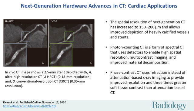
■ The spatial resolution of next-generation CT has increased to 150–200 µm and allows improved depiction of heavily calcified vessels and stents.
■ Photon-counting CT is a form of spectral CT that uses detectors to enable high spatial resolution, multicontrast imaging, and improved material decomposition.
■ Phase-contrast CT uses refraction instead of attenuation-based x-ray imaging to provide improved resolution and three times greater soft-tissue contrast than attenuation-based CT.
Introduction
There have been significant advances in CT hardware since its initial development in the early 1970s. Current detectors allow isotropic spatial resolution of approximately 0.25–0.5 mm. Gantry rotation speed is now 250 msec with dual-source imaging, enabling high-pitch helical CT scanning of the entire torso in 1–2 seconds (1,2). However, challenges remain, particularly for cardiac CT; these challenges include spatial resolution of microstructures, tissue characterization, and soft-tissue contrast (3). In regard to spatial resolution of microstructures, the normal epicardial coronary luminal diameter ranges from 1.0 to 4.6 mm (4). Evaluation of cardiovascular risk now includes coronary plaque quantification and identification of smaller anatomic features that are at or below the current spatial resolution limits (5,6). In regard to tissue characterization, quantitative tissue characterization is a major diagnostic strength of cardiac MRI that CT has not yet accomplished (7). Regarding soft-tissue imaging in the heart, iodinated contrast material is required because contrast resolution is not yet high enough; however, while exogenous contrast yields a high contrast-to-noise ratio of 10–20:1, these agents cannot be used in all patients.
To overcome these challenges, we present a narrative review on three hardware advances within CT that are nearing the beginning of clinical application and that we believe will affect the future of cardiovascular imaging. These include next-generation ultra-high-resolution (UHR) CT, spectral imaging with photon-counting (PC) CT, and phase-contrast CT (Fig 1). We acknowledge the contribution of software advances, including artificial intelligence (8), deep learning (9–11), fractional flow reserve CT (12), and multiple other advances, but we did not include them within the scope of the review. Reviews of software advances can be found in the cited sources (13–15). In this review, we describe hardware advances in CT and focus on their application to cardiac CT as a unique and important driver of change in the CT field.
Figure 1:
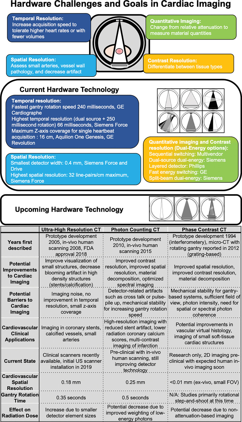
Clinical challenges to cardiac CT, including temporal, spatial, and contrast resolution, and quantitative imaging. Current technologic approaches and upcoming approaches with ultra-high-resolution CT, photon-counting CT, and phase-contrast CT with potential clinical cardiac applications. FDA = Food and Drug Administration, FOV = field of view, N/A = not applicable.
UHR CT
At present, nearly all conventional CT scanners are multidetector CT units that use arrays of energy-integrating detectors (EIDs) to achieve spatial resolution of approximately 0.25–0.5 mm. The terms high-resolution CT and thin-section CT usually refer to specific methods for parenchymal lung imaging using a slice thickness of 1–2 mm. In this review, UHR CT is defined as CT with the potential to improve spatial resolution from approximately 400–450 µm to nearly 150–200 μm, corresponding to approximately 49.5 line pairs per centimeter (16,17). While one way to achieve ultrahigh spatial resolution is through reduction in detector size, spatial resolution is also determined by other factors, including x-ray tube focal spot size, magnification by position of the x-ray source, number of projections recorded per gantry rotation, and reconstructed kernel shape, algorithm, and voxel size. Thus, direct comparisons of detector size alone may not accurately reflect differences in spatial resolution.
Cardiac CT presents a unique set of problems to spatial resolution. Improvements in coronary stent technology have made intervention of small-vessel (<2.75 mm) stenosis feasible (18) and an important clinical consideration (19). In addition, coronary plaque size and distribution are frequently measured using coronary CT angiography because the quantity of plaque affects patient outcome (20,21). Plaque subtypes (lipid core, calcified, and noncalcified components) and certain plaque features (ulcerated plaque, napkin sign, areas of low-attenuation plaque, and spotty calcification) are associated with incident cardiovascular events (22). However, clear visualization of these vessels and the small plaque features within coronary walls (ranging from tens to hundreds of micrometers) are at or below the spatial resolution limits of cardiac CT (5,20,21,23).
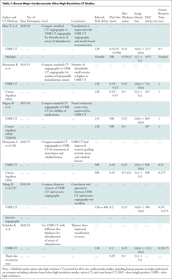
To address the issue of spatial resolution, the only currently available clinically applicable option for UHR cardiac imaging is the Aquilion Precision CT platform (Canon Medical Systems, Otawara, Tochigi, Japan). In this form of UHR CT, the minimum detector element size was reduced to 0.25 × 0.25 mm versus the previous Canon Medical Systems detector element size of 0.5 × 0.5 mm (other comparable models range from 0.4 to 0.625 mm). To maximize spatial resolution for this platform, x-ray tubes were designed with adjustable focal spot sizes down to 0.4 × 0.5 mm from the previous 0.9 × 0.8-mm focal spot size in Canon Medical Systems models (notably, Somatom Force [Siemens Healthineers, Erlangen, Germany] has a similar focal spot size of 0.4 × 0.5 mm; other comparable models range from 0.6–1.1 × 0.7–1.6 mm) (24). Model-based iterative reconstruction techniques were also incorporated (25). Research is taking place on cardiovascular applications (Table 1), with US-based systems having been recently installed at Johns Hopkins Hospital and the University of California at Davis. For this CT platform, a spatial resolution of 150 µm at 0% modulation transfer function (MTF) has been reported (16), which may represent a substantial improvement over that reported with other platforms. MTF is a continuous function expressing the ability of an imaging system to resolve objects at different spatial frequencies. While the maximum resolvable spatial frequency is 0% MTF, this does not necessarily imply superior image quality across all spatial frequencies. Full MTF profiles may be difficult to find, making full comparison of resolution between CT platforms across a spatial spectrum difficult (26).
Table 1:
Recent Major Cardiovascular Ultra-High-Resolution CT Studies
Improved spatial resolution is not without drawbacks. Image noise is partly dependent on the ratio of photons per detector element; therefore, reduction of EID detector dimensions by 50% theoretically requires quadrupling of x-ray photon flux to maintain equivalent signal-to-noise ratio. However, reconstruction methods can offset this image noise penalty (27,28). In the future, head-to-head comparisons among different UHR strategies will define advantages and disadvantages of the different approaches. Smaller detector size also means that with 160 slices, z-axis coverage is only 4 cm, requiring multivolume or helical acquisitions that increase motion artifact susceptibility. In comparison, two current lower-spatial-resolution systems offer 16-cm full-volume cardiac coverage with 320 × 0.5 mm (Canon Medical Systems) or 256 × 0.625 mm (GE Healthcare) arrays (29). Gantry rotation time of 350 msec is also slower than with current lower-spatial-resolution platforms (GE Healthcare [240 msec, single source], Philips [270 msec, single source], and Siemens [250 msec, dual source]), which limits temporal resolution (Fig 1) (24).
Cardiac Applications of UHR CT
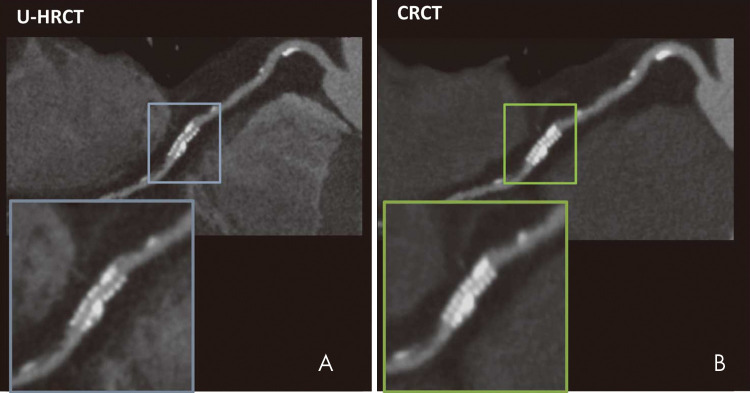
Coronary artery imaging with UHR CT was performed by Motoyama et al in 2018 (30). Intraluminal stent dimensions and stenosis of calcified lesions with UHR CT (spatial resolution, 0.18 mm) were compared with conventional-resolution coronary CT angiography (spatial resolution, 0.35 mm) or invasive coronary angiography. A total of 59 patients underwent both UHR CT and invasive coronary angiography; UHR CT had a positive predictive value of 80% and a negative predictive value of 100% for stenosis of 70% or more on a per-segment analysis. Comparisons between UHR CT and standard coronary CT angiography were available for 17 measurements of in-stent restenosis. Readers visualized the stent lumen in 16 stents for UHR CT and in 11 stents for conventional-resolution CT. Quantitative analysis enabled accurate identification of larger lumens in both stents and highly calcified lesions using UHR CT, likely representing the improved spatial resolution (Fig 2). A smaller study of 38 patients with UHR CT compared with diameter stenosis measured with invasive coronary angiography had per-segment sensitivity of 100% in the detection of stenosis of more than 30% but a lower specificity of 67%, with a small bias toward overestimation of stenosis (mean, 4% ± 7 [standard devation]) (25). Given the relationship between spatial resolution and radiation dose in UHR CT, it is noted that the dose reported in these two studies was 7.4 mSv and 5.4 mSv, respectively. This is a clinically feasible dose in the study patients with reported body mass indexes of 22.9 and 25 kg/m2, respectively (25,30). These body mass indexes are lower than those of many patients with cardiovascular disease in Western countries who may require higher x-ray tube current and energy. Small focal spot imaging used in UHR CT requires lower power output to avoid damaging the anode of the x-ray tube. Thus, further studies in obese patients are needed. However, overall, these improvements have been substantial and of great clinical relevance for cardiac imaging, particularly in patients with coronary stents or heavy calcification due to advanced cardiovascular disease.
Figure 2:
In vivo CT image shows a 2.5-mm stent depicted with, A, ultra-high-resolution CT (U-HRCT) (0.18-mm resolution) and, B, conventional-resolution CT (CRCT) (0.35-mm resolution). (Reprinted, with permission, from reference 30.)
Photon-counting CT
PC CT is a cutting-edge form of spectral CT that could also represent a transformative technologic breakthrough. Spectral CT refers to the use of x-ray photon energy–dependent information to differentiate and quantify material composition in a three-dimensional space. The concept of spectral CT was first proposed by Godfrey Hounsfield at the time of his original descriptions of x-ray CT, where he addressed the determination of atomic number of material, and suggested that the subtraction of images at 100 kV from 140 kV could enable differentiation of calcium from iodine (31). To extract spectral data, spatially and temporally co-registered data sets of spectrally distinct photon energies are required, which has not been feasible historically. However, in recent years, most major CT vendors have developed clinical dual-energy CT technology. Importantly, PC CT technologies that allow for more than two energies are also in development.
The physical basis for spectral CT has been previously reviewed (32). In brief, the linear attenuation coefficient of any given voxel can be estimated by imaging with two separate energies and expressing it as the sum of two basis functions. Typically, the two functions represent either the photoelectric effect and Compton scattering (attenuation basis) or two assumed materials (material basis). The combination does not necessarily reflect the true components of the object but expresses what combination of the two basis materials would accurately generate the measured linear attenuation coefficient. Use of more than two basis functions requires more than two energies, but this technique enables more accurate representation of the linear attenuation coefficient of a voxel and closer identification of materials. Extraction of the energy-dependent spectral information is termed material decomposition. This adds material-specific information, such as effective atomic number, as well as the ability to simulate images under different conditions (such as subtraction of calcium or contrast) or across different x-ray energies (32).
Photon-counting detector (PCD) technology combines the benefits of UHR and spectral CT by using a different type of detector. This technology has also been recently reviewed (33). In brief, traditional EIDs measure the sum (integral) of the energies of the individual photons projected through an object. Multiple energies are measured with high- and low-energy data sets separated either physically (dual-layer, twin-beam, or dual-source CT) or temporally (sequential and rapid-switching CT) (Fig 1). Instead of arrays of EIDs, PCDs are single solid-state detectors. Energy separation is performed using user- or manufacturer-specified sequential energy thresholds. When a photon hits a PCD, the energy pulse of the photon is measured, and a photon is “counted” for each surpassed threshold. By subtracting counts in sequential thresholds from each other, photon counts within each energy bin are obtained (33).
Current challenges include accurately registering and measuring photon energies. Specifically, cross-talk effects (“k-escape,” “charge-sharing,” or fluorescence), where multiple detector pixels register a single higher energy charge due to scattering, can cause misregistration of high-energy photons as multiple lower-energy photons. Pulse pile-up effects occur if multiple photons interact with the detector within too brief a timeframe for the detector to resolve the separate events, resulting in multiple lower-energy charges incorrectly registered as a single higher-energy photon (33). Cross talk can be decreased by summing adjacent pixels during coincident events to identify the true energy and by assigning the count to the area with the highest energy (34,35). However, this results in increasing susceptibility to pulse pile-up, which has required multiple approaches to address. These approaches have included beam filtering to avoid excessive flux, electronics improvements to decrease overall deadtime by layering detector elements, and post hoc compensation algorithms and reconstruction methods (36).
PC CT is currently only available on experimental scanners, with Siemens prototypes being used to perform imaging in human volunteers at three locations (33) and a Philips prototype being tested in Lyons, France. Multiple small human studies totaling more than 100 patients have already been performed and published by the National Institutes of Health and the Mayo Clinic. These studies include varying scenarios of diagnostic quality PC CT, including abdominal, chest, cardiovascular, and brain imaging to demonstrate technical feasibility (37–45).
Potential Advantages of PC CT Compared with EIDs
There are multiple theoretical advantages of CT examinations that use PCDs instead of EIDs. The direct conversion of x-ray photons to electric charges in solid-state PCDs means that detector element size is not determined by physical separation between elements. Therefore, PCD element size can be quite small (range, 0.11 × 0.11 mm to 0.5 × 0.5 mm physical detector pixel size). In contrast, EIDs require light-reflecting septa between elements of scintillating crystals, which makes manufacturing of small elements difficult. Initial studies in UHR PC CT using a detector mode with 0.25-mm apparent pixel size at the isocenter compared with a 0.5-mm detector mode (standard resolution) showed improvements in spatial resolution in humans (42,44) and in phantoms with coronary stents (46–48), albeit at the cost of increased noise when using high-resolution reconstruction (37).
Additionally, in PCDs, all photons are weighted equally instead of being weighted by their energies in EID. This results in accurate weighting of photons in the low-energy range, where there is greater contrast between soft tissues, even without using spectral information. Setting minimum energy thresholds filters out electronic noise, which improves reduced-dose (20 vs 80 mAs) performance of the scanner, especially in a screening task, such as coronary calcium scoring. These factors reduced the radiation dose of PC CT for coronary artery calcium scoring CT by 75% compared with EID, while maintaining image quality in human studies (49). Thus, PC CT may improve contrast resolution and decrease noise simultaneously.
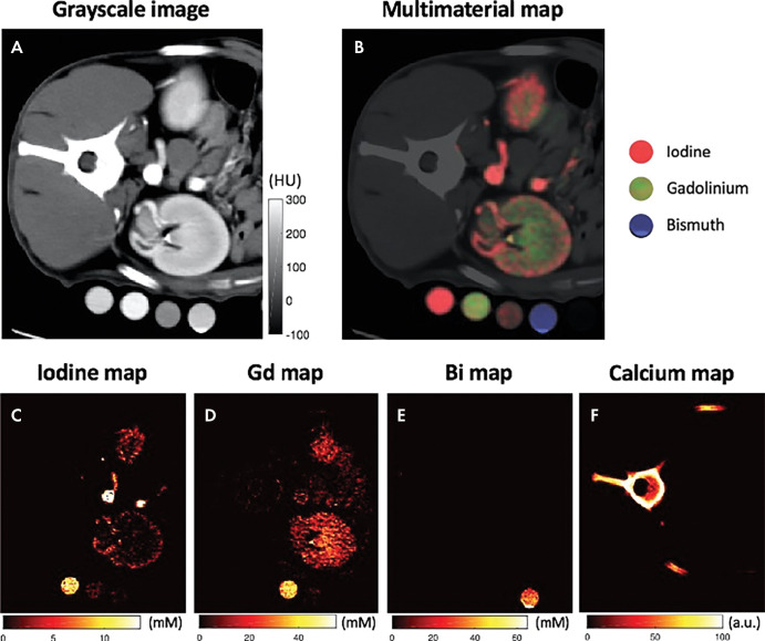
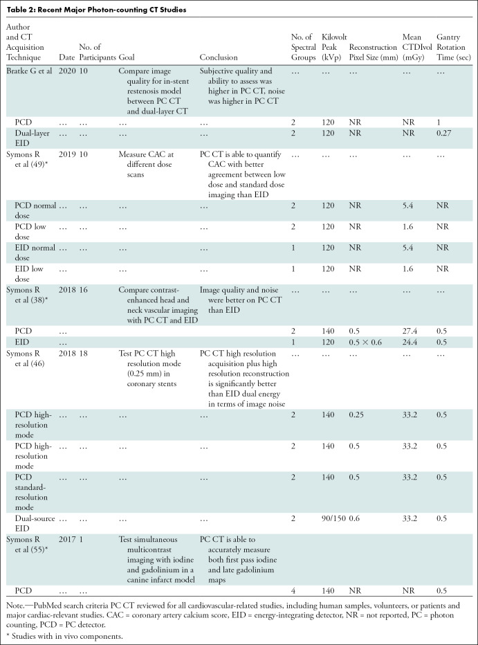
Finally, PC CT theoretically has superior spectral imaging compared with spectral CT using EID detectors. PCD spectral information is inherently co-registered, and spectral separation may be more effective with the adjustable energy thresholds (50,51). PCD CT can also use more than two energy bins, improving the ability to quantify materials within a given space (52) and making multicontrast imaging possible (Fig 3) (53–57). However, using more energy bins does result in decreased photon count and increased noise in each bin, although reconstruction and postprocessing denoising algorithms have been proposed (58,59). In summary, PCDs may revolutionize CT by offering increased contrast, lower noise, and spectral capabilities, while improving spatial resolution, with multiple cardiovascular-related studies underway (Table 2).
Figure 3:
Multicontrast photon-counting CT images in a canine abdomen. A, Gray-scale CT image obtained using photons with single-energy bin. B, Multimaterial map obtained using multienergy reconstruction, labeling iodine, gadolinium, and bismuth with different colors, resulting in different distributions. C, Iodine map alone. D, Gadolinium (Gd)-enhanced map alone. E, Bismuth (Bi) map alone. F, Calcium map alone. (Reprinted, with permission, from reference 55.)
Table 2:
Recent Major Photon-counting CT Studies
Cardiac Applications of PC CT
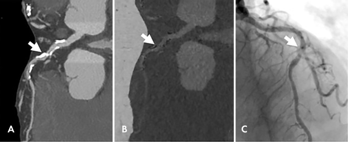
Because of the superior spectral abilities already cited, PC CT is expected to exploit current dual-energy techniques for cardiovascular applications within cardiology. For example, virtual monochromatic images optimize the visibility of coronary stenosis (60) and infarcted myocardium (61,62); virtual noncalcium images improve visualization of the coronary artery lumen (Fig 4) (63); and quantification of iodine content may improve myocardial perfusion imaging (64) and extracellular volume measurement (65). Beyond dual-energy capabilities, the spectral potential of PC cardiac CT has not been fully demonstrated. An exception is a proof-of-concept study with PC CT that evaluated iodine first-pass images and delayed gadolinium-enhanced images simultaneously in a canine model of myocardial infarction (53). Further improvement in basis material decomposition is needed (66). A dual-source PC CT detector developed by Tao et al may improve temporal resolution while maintaining UHR and spectral advantages (67). Refinement of spectral applications, radiation reduction, and 250-μm high-spatial-resolution capabilities of PC CT are likely to be initial applications of this technology.
Figure 4:
Images in a 92-year-old woman with chest pain. A, Dual-energy coronary CT angiogram. B, Material decomposition–based calcium suppression and, C, corresponding invasive coronary angiogram show a patent lumen visualized with calcium suppression imaging. Arrow indicates the same middle left anterior descending coronary lesion. (Reprinted, with permission, from reference 63.)
Phase-Contrast CT
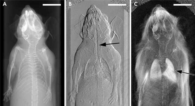
Current CT technologies achieve contrast resolution due to the attenuation of x-ray photons or the use of intravenous iodinated contrast media to detect small differences in attenuation between soft tissues. Instead of attenuation, an alternative contrast mechanism is to exploit x-ray wave properties of refraction, phase shift, or ultrasmall angle scattering. These modes of contrast in CT are known as phase-contrast CT and dark-field CT, which reveal different tissue characteristics and improve soft-tissue contrast resolution versus attenuation-based CT (68). Phase-contrast and attenuation imaging should be conceptualized as complementary forms of imaging that provide different information (Fig 5) (69).
Figure 5:
X-ray images in a mouse obtained with, A, standard attenuation-based imaging, B, phase-contrast imaging, and, C, dark-field imaging. Arrow indicates regions of enhanced contrast in the trachea (B) and lungs (C). (Reprinted, with permission, from reference 69.)
Phase-contrast imaging uses either the organized changes in x-ray phase (Φ) or refraction (α) to generate contrast (70,71). The degree of change is determined by the refractive index of the object (δ), related to electron density, and the wavelength of the x-ray. Dark-field imaging uses disorganized scatter from microscopic density gradients in the medium to create contrast. This reveals tissue-specific characteristics, like microstructural inhomogeneity (72). More detailed technical explanations can be found in the referenced literature and fall outside the scope of this review (73,74).
Benefits of Phase-Contrast CT
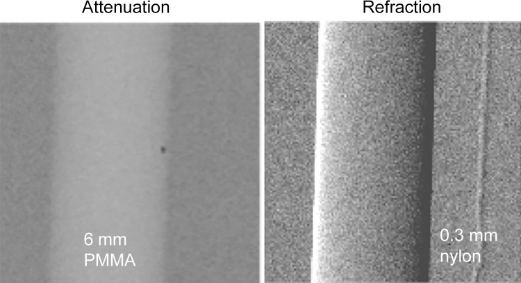
Phase-contrast and dark-field imaging have a strong theoretical advantage over attenuation-based CT for soft-tissue contrast. This may be highly applicable to cardiac imaging. The refractive index (δ) of soft tissue is three orders of magnitude greater than the absorptive index (β) at standard x-ray energy and diminishes less with increased photon energy than β. This means greater soft-tissue contrast with higher x-ray energy (75). Phase-contrast imaging may show improved edge contrast due to high sensitivity to density gradients, which could improve high-resolution imaging of stents or catheters. This capability is illustrated in Figure 6 (75). The use of higher energy x-rays without relying on attenuation could reduce radiation absorption (70,71).
Figure 6:
Attenuation-based radiograph and phase-contrast refraction radiograph of a poly(methyl methacrylate) (PMMA) rod and a 0.3-mm nylon filament immersed in a 5-cm-thick water bath. The images were obtained at 60 kVp with a glancing angle interferometer. The computed radiation dose is 2 mGy absorbed dose. The thin filament is invisible on the conventional image (left) but has good contrast with refraction (right).
Preclinical studies including in vivo imaging show the potential of phase-contrast CT and dark-field imaging. A large body of these studies are from the Munich Biomedical Physics group under the purview of Dr Franz Pfeiffer. In vivo imaging has been performed in swine (76,77) and mouse (78) models. Pulmonary and mammography applications appear particularly promising (79,80). Efforts are being made to increase the field of view and improve temporal resolution and mechanical stability (81,82).
Development of Phase-Contrast CT toward Clinical Cardiovascular Imaging
Phase-contrast CT has not been developed for in vivo human application. Phase-contrast radiography has existed since the 1960s, but the first published phase-contrast CT study was performed by Momose et al in 1994 using monochromatic x-rays from a synchrotron (83). Clinical cardiac application of phase-contrast CT requires multiple items for success: sufficient mechanical stability to both rotate and measure small changes in x-rays, adequate field of view, and clinically feasible nonsynchrotron x-ray sources with energies sufficient for clinical imaging.
Synchrotron radiation has been used, as it provides spectrally and spatially coherent high-flux photons, where refraction or phase changes can be easily measured; however, this is not clinically feasible. Some limitations in stability, field of view, and need for x-ray monochromacy and spatial coherence have been addressed in part by using a Talbot-Lau shearing interferometer (84). This design places gratings between the x-ray source and the imaged object, which creates spatial coherence and decodes the phase shifts from the object. Glancing angle interferometry (Fig 7) angles the Talbot-Lau grating, which increases the interferometer fringe contrast. This interferometer set-up enabled the first demonstration of high-energy phase-contrast CT with clinically compatible absorbed dose exposure (8 mGy) (75,85). The current designs maintain beam spatial coherence using a standard polychromatic x-ray tube, with sufficient mechanical stability to apply to CT, and can also simultaneously acquire dark-field imaging and attenuation images (72). With these principles, the Munich group has recently created a dark-field chest x-ray prototype. It has received approval from the German Federal Office for Radiation Protection to begin in vivo patient imaging to detect incipient alveolar inflammation and edema from COVID-19 infection. It allows enhanced soft-tissue resolution and lower radiation doses than does attenuation-based x-ray imaging (72,86).
Figure 7:
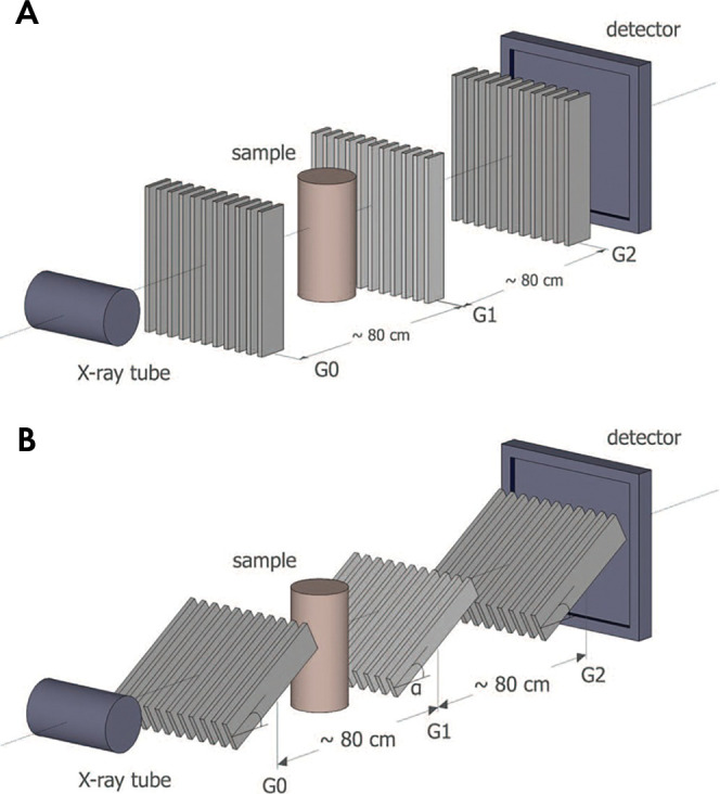
A, Talbot-Lau interferometer set-up with, B, glancing angle grids. G = grating. (Reprinted, with permission, from reference 75.)
High-intensity laser-driven x-ray sources may be the next step for cardiac phase-contrast imaging. While the Talbot-Lau approach has addressed issues with coherence, intensity is also important, as the technology moves from small-object studies to studies in larger, more clinically applicable subjects. Conventional x-ray tubes are suboptimally suited for phase-contrast imaging. This is due to the need for spatial coherence and long propagation distances for the phase effects to develop (order of meters). The photon concentration from conventional x-rays at these distances is low. The next step for cardiac phase-contrast imaging may include high-intensity lasers (peak power in the 100-TW range and femtosecond pulse duration). These lasers produce an ultrabright, directional, and spatially coherent x-ray source. By using ultrashort x-ray pulses with a high repetition rate, these lasers may address temporal resolution for cardiac phase-contrast imaging. The 100-TW class lasers are becoming commercially affordable, and worldwide efforts to develop laser-based phase-contrast imaging are ongoing (87,88), as demonstrated by laser-driven x-ray phase-contrast CT of medically relevant samples (89).
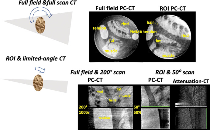
Field-of-view limitations may make phase-contrast CT more applicable for cardiovascular imaging. Phase-contrast CT is well-suited to limited-angle, region-of-interest (ROI), or interior tomography. A practical option for cardiac CT would be to use a scanner with a small field of view (Fig 8) with ROI and phase-contrast tomosynthesis (limited-angle CT) to target a small organ. Theoretical and experimental results show that phase-contrast projections are better suited for ROI CT than for conventional attenuation-based projections (90,91). Figure 9 shows simultaneous ROI and tomosynthesis of a fresh tissue phantom at high energy, obtained with a glancing angle interferometer operated at 80 kVp. ROI phase-contrast CT using smaller gratings may reduce both the effective dose and the scan time, even at high spatial resolution.
Figure 8:
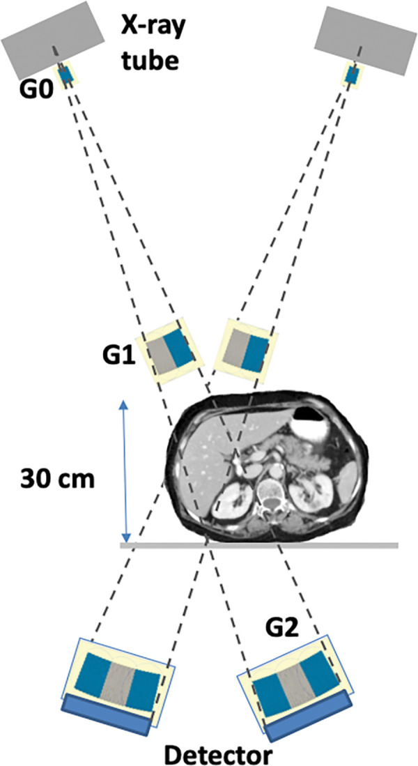
High-energy region-of-interest phase-contrast tomosynthesis system for the internal organs based on the glancing angle interferometer design. G = grating.
Figure 9:
Top: Full-field and region of interest (ROI) phase-contrast CT (PC-CT) scans of fresh pig soft tissues in water at diagnostic energy. The imaged section is 25 mm in diameter. Bottom: Full-field and full-scan phase-contrast CT images and simultaneous region-of-interest and limited-angle phase-contrast tomosynthesis of soft tissues in water. Also shown is the conventional attenuation–based tomosynthesis image, indicating much less soft-tissue contrast than in the phase-contrast image. PMMA = poly(methyl methacrylate).
Cardiac Applications of Phase-Contrast CT
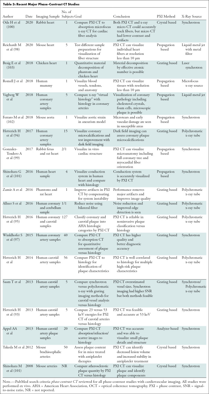
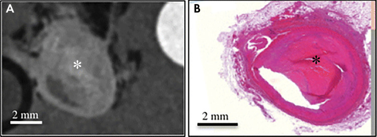
Cardiovascular focused phase-contrast CT studies are reviewed in Table 3. The bulk of cardiovascular studies have performed “virtual histology,” comparing phase-contrast CT of coronary and carotid atherosclerosis with histology (92–97). These studies identify high-risk plaque features and quantify plaque contents with excellent correlation with histology (Fig 10) and spatial resolution to around 10 μm (95). In 2017, Habbel et al compared ex vivo human coronary phase-contrast CT with optical coherence tomography, with histopathology as the reference standard. In a sample of 241 matched cross sections, phase-contrast CT images had superior correlation with histology findings between volumetric measures of vessel, lumen, and plaque versus optical coherence tomography. Phase-contrast CT also yielded superior identification of lipid-rich, fibrous, or calcified plaque (92). Other applications have leveraged the 10-μm spatial resolution and high soft-tissue contrast. These have included visualizing myocardial fiber orientation (98–100), identifying the cardiac conduction system (101), visualizing microscopic vascular damage (102), and performing cardiac material decomposition (103). These experimental techniques may enable noninvasive high-resolution imaging of high-risk plaque and identification of subtle myocardial abnormalities in patients with cardiac disease.
Table 3:
Recent Major Phase-Contrast CT Studies
Figure 10:
Ex vivo images of complex fibrous material (*) within plaque in the right coronary artery obtained, A, with phase-contrast CT and, B, at histology. (Reprinted, with permission, from reference 95.)
Conclusion
Hardware advances, including ultra-high-resolution (UHR) CT, photon-counting CT, and phase-contrast CT, are opening new aspects to the field of cardiac CT. UHR CT improves imaging of heavily calcified arteries, cardiac valves, and stents. Functional applications for further exploration include atherosclerotic plaque characterization, stent imaging, fractional flow reserve, myocardial perfusion imaging, and microvessel imaging. Photon-counting CT uses multiple photon energies to reduce artifacts, improve contrast, and perform material decomposition. Its potential could revolutionize medical imaging, but the detector technology needs further refinement for clinical applications. Finally, phase-contrast CT uses x-ray refraction properties to improve spatial and soft-tissue contrast. Potential applications of phase-contrast CT to breast and lung cancer in addition to pulmonary parenchymal disease processes complement its potential in cardiovascular medicine. Despite technical hurdles, hardware advances in cardiac CT continue to expand and have the potential to transform cardiac imaging.
A.C.K. supported by the National Institutes of Health (grant T32HL116273) and Doris Duke Charitable Foundation (grant 2020059). J.A.C.L. supported by Canon Medical Systems, Astra Zeneca, and MedImmune.
Disclosures of Conflicts of Interest: A.C.K. disclosed no relevant relationships. A.P. Activities related to the present article: disclosed no relevant relationships. Activities not related to the present article: is a consultant for Cardiowise, institution received grants from Siemens Healthcare and Canon Medical Research, holds stock options in Cardiowise. Other relationships: disclosed no relevant relationships. D.S. Activities related to the present article: disclosed no relevant relationships. Activities not related to the present article: disclosed no relevant relationships. Other relationships: Johns Hopkins University was assigned U.S. patent 9,329,141 for the Glancing Angle Interferometer. D.A.B. disclosed no relevant relationships. J.A.C.L. disclosed no relevant relationships. A.C.K. disclosed no relevant relationships.
Abbreviations:
- EID
- energy-integrating detector
- PC
- photon counting
- PCD
- PC detector
- UHR
- ultra-high-resolution
References
- 1.Schmidt B, Grant K, Flohr TG, Allmendinger T. Cardiac CT Platforms: State of the Art. In: Schoepf UJ, ed. CT of the Heart. 2nd ed. New York, NY: Humana/Springer, 2019; 51–67. [Google Scholar]
- 2.Flohr TG, Allmendinger T, Bruder H, Schwemmer C, Kappler S, Schmidt B. Future Technological Advances in Cardiac CT. In: Schoepf UJ, ed. CT of the Heart. 2nd ed. New York, NY: Humana/Springer, 2019; 873–892. [Google Scholar]
- 3.Schoepf UJ, ed. CT of the Heart. 2nd ed. New York, NY: Humana/Springer, 2019. [Google Scholar]
- 4.Dodge JT, Jr, Brown BG, Bolson EL, Dodge HT. Lumen diameter of normal human coronary arteries. Influence of age, sex, anatomic variation, and left ventricular hypertrophy or dilation. Circulation 1992;86(1):232–246. [DOI] [PubMed] [Google Scholar]
- 5.Ahmadi A, Argulian E, Leipsic J, Newby DE, Narula J. From Subclinical Atherosclerosis to Plaque Progression and Acute Coronary Events: JACC State-of-the-Art Review. J Am Coll Cardiol 2019;74(12):1608–1617. [DOI] [PubMed] [Google Scholar]
- 6.Kwan AC, Cater G, Vargas J, Bluemke DA. Beyond coronary stenosis: coronary computed tomographic angiography for the assessment of atherosclerotic plaque burden. Curr Cardiovasc Imaging Rep 2013;6(2):89–101. [DOI] [PMC free article] [PubMed] [Google Scholar]
- 7.Seraphim A, Knott KD, Augusto J, Bhuva AN, Manisty C, Moon JC. Quantitative cardiac MRI. J Magn Reson Imaging 2020;51(3):693–711. [DOI] [PubMed] [Google Scholar]
- 8.Siegersma KR, Leiner T, Chew DP, Appelman Y, Hofstra L, Verjans JW. Artificial intelligence in cardiovascular imaging: state of the art and implications for the imaging cardiologist. Neth Heart J 2019;27(9):403–413. [DOI] [PMC free article] [PubMed] [Google Scholar]
- 9.Litjens G, Ciompi F, Wolterink JM, et al. State-of-the-art deep learning in cardiovascular image analysis. JACC Cardiovasc Imaging 2019;12(8 Pt 1):1549–1565. [DOI] [PubMed] [Google Scholar]
- 10.Boedeker K. AiCE Deep Learning Reconstruction: Bringing the power of Ultra-High Resolution CT to routine imaging. Tustin, Calif: Canon Medical Systems Corporation, 2019. [Google Scholar]
- 11.Benz DC, Benetos G, Rampidis G, et al. Validation of deep-learning image reconstruction for coronary computed tomography angiography: Impact on noise, image quality and diagnostic accuracy. J Cardiovasc Comput Tomogr 2020. 10.1016/j.jcct.2020.01.002. Published online January 13, 2020. [DOI] [PubMed] [Google Scholar]
- 12.Nørgaard BL, Terkelsen CJ, Mathiassen ON, et al. Coronary CT angiographic and flow reserve-guided management of patients with stable ischemic heart disease. J Am Coll Cardiol 2018;72(18):2123–2134. [DOI] [PubMed] [Google Scholar]
- 13.Weir-McCall JR, Nicol E, Abbara S, et al. Highlights of the fourteenth annual scientific meeting of the Society of Cardiovascular Computed Tomography. J Cardiovasc Comput Tomogr 2020;14(2):118–123. [DOI] [PubMed] [Google Scholar]
- 14.Chandrashekhar Y; JACC: Cardiovascular Imaging Editors. What Is of Recent Interest in Cardiac CT: Insights From the JACC Family of Journals. J Am Coll Cardiol 2019;73(25):3352–3355. [DOI] [PubMed] [Google Scholar]
- 15.Nicol ED, Norgaard BL, Blanke P, et al. The future of cardiovascular computed tomography: advanced analytics and clinical insights. JACC Cardiovasc Imaging 2019;12(6):1058–1072. [DOI] [PubMed] [Google Scholar]
- 16.Food and Drug Administration 510(k) Clearances. Aquilion Precision (TSX-304A/2) V8.6 with FIRST 3.0 501(k) Clearance. Department of Health and Human Services, Food and Drug Administration. https://www.accessdata.fda.gov/cdrh_docs/pdf17/K173468.pdf. Published 2018. Accessed November 9, 2018. [Google Scholar]
- 17.Hata A, Yanagawa M, Honda O, et al. Effect of Matrix Size on the Image Quality of Ultra-high-resolution CT of the Lung: Comparison of 512 × 512, 1024 × 1024, and 2048 × 2048. Acad Radiol 2018;25(7):869–876. [DOI] [PubMed] [Google Scholar]
- 18.Biondi-Zoccai G, Moretti C, Abbate A, Sheiban I. Percutaneous coronary intervention for small vessel coronary artery disease. Cardiovasc Revasc Med 2010;11(3):189–198. [DOI] [PubMed] [Google Scholar]
- 19.Silverio A, Buccheri S, Venetsanos D, et al. Percutaneous treatment and outcomes of small coronary vessels: a SCAAR report. JACC Cardiovasc Interv 2020;13(7):793–804. [DOI] [PubMed] [Google Scholar]
- 20.Motoyama S, Ito H, Sarai M, et al. Plaque characterization by coronary computed tomography angiography and the likelihood of acute coronary events in mid-term follow-up. J Am Coll Cardiol 2015;66(4):337–346. [DOI] [PubMed] [Google Scholar]
- 21.Williams MC, Moss AJ, Dweck M, et al. Coronary artery plaque characteristics associated with adverse outcomes in the SCOT-HEART study. J Am Coll Cardiol 2019;73(3):291–301. [DOI] [PMC free article] [PubMed] [Google Scholar]
- 22.Virmani R, Kolodgie FD, Burke AP, Farb A, Schwartz SM. Lessons from sudden coronary death: a comprehensive morphological classification scheme for atherosclerotic lesions. Arterioscler Thromb Vasc Biol 2000;20(5):1262–1275. [DOI] [PubMed] [Google Scholar]
- 23.Arbab-Zadeh A, Fuster V. From Detecting the Vulnerable Plaque to Managing the Vulnerable Patient: JACC State-of-the-Art Review. J Am Coll Cardiol 2019;74(12):1582–1593. [DOI] [PubMed] [Google Scholar]
- 24.DAIC : Diagnostic and Interventional Cardiology. Cardiac CT Systems Comparison Chart. https://www.dicardiology.com/content/cardiac-ct-systems. Published 2019. Accessed April 26, 2020.
- 25.Takagi H, Tanaka R, Nagata K, et al. Diagnostic performance of coronary CT angiography with ultra-high-resolution CT: Comparison with invasive coronary angiography. Eur J Radiol 2018;101:30–37. [DOI] [PubMed] [Google Scholar]
- 26.Friedman SN, Fung GS, Siewerdsen JH, Tsui BM. A simple approach to measure computed tomography (CT) modulation transfer function (MTF) and noise-power spectrum (NPS) using the American College of Radiology (ACR) accreditation phantom. Med Phys 2013;40(5):051907. [DOI] [PMC free article] [PubMed] [Google Scholar]
- 27.10. Spatial Resolution in CT. J ICRU 2012;12(1):107–120. [Google Scholar]
- 28.Lin E, Alessio A. What are the basic concepts of temporal, contrast, and spatial resolution in cardiac CT? J Cardiovasc Comput Tomogr 2009;3(6):403–408. [DOI] [PMC free article] [PubMed] [Google Scholar]
- 29.Lewis MA, Pascoal A, Keevil SF, Lewis CA. Selecting a CT scanner for cardiac imaging: the heart of the matter. Br J Radiol 2016;89(1065):20160376. [DOI] [PMC free article] [PubMed] [Google Scholar]
- 30.Motoyama S, Ito H, Sarai M, et al. Ultra-High-Resolution Computed Tomography Angiography for Assessment of Coronary Artery Stenosis. Circ J 2018;82(7):1844–1851. [DOI] [PubMed] [Google Scholar]
- 31.Hounsfield GN. Computerized transverse axial scanning (tomography). 1. Description of system. Br J Radiol 1973;46(552):1016–1022. [DOI] [PubMed] [Google Scholar]
- 32.McCollough CH, Leng S, Yu L, Fletcher JG. Dual- and Multi-Energy CT: Principles, Technical Approaches, and Clinical Applications. Radiology 2015;276(3):637–653. [DOI] [PMC free article] [PubMed] [Google Scholar]
- 33.Willemink MJ, Persson M, Pourmorteza A, Pelc NJ, Fleischmann D. Photon-counting CT: technical principles and clinical prospects. Radiology 2018;289(2):293–312. [DOI] [PubMed] [Google Scholar]
- 34.Taguchi K, Polster C, Lee O, Stierstorfer K, Kappler S. Spatio-energetic cross talk in photon counting detectors: Detector model and correlated Poisson data generator. Med Phys 2016;43(12):6386–6404. [DOI] [PubMed] [Google Scholar]
- 35.Koenig T, Hamann E, Procz S, et al. Charge summing in spectroscopic x-ray detectors with high-Z sensors. IEEE Trans Nucl Sci 2013;60(6):4713–4718. [Google Scholar]
- 36.Taguchi K. Energy-sensitive photon counting detector-based X-ray computed tomography. Radiological Phys Technol 2017;10(1):8–22. [DOI] [PubMed] [Google Scholar]
- 37.Pourmorteza A, Symons R, Henning A, Ulzheimer S, Bluemke DA. Dose Efficiency of Quarter-Millimeter Photon-Counting Computed Tomography: First-in-Human Results. Invest Radiol 2018;53(6):365–372. [DOI] [PubMed] [Google Scholar]
- 38.Symons R, Reich DS, Bagheri M, et al. Photon-Counting Computed Tomography for Vascular Imaging of the Head and Neck: First In Vivo Human Results. Invest Radiol 2018;53(3):135–142. [DOI] [PMC free article] [PubMed] [Google Scholar]
- 39.Pourmorteza A, Symons R, Reich DS, et al. Photon-counting CT of the brain: in vivo human results and image-quality assessment. AJNR Am J Neuroradiol 2017;38(12):2257–2263. [DOI] [PMC free article] [PubMed] [Google Scholar]
- 40.Symons R, Pourmorteza A, Sandfort V, et al. Feasibility of dose-reduced chest CT with photon-counting detectors: initial results in humans. Radiology 2017;285(3):980–989. [DOI] [PMC free article] [PubMed] [Google Scholar]
- 41.Pourmorteza A, Symons R, Sandfort V, et al. Abdominal imaging with contrast-enhanced photon-counting CT: first human experience. Radiology 2016;279(1):239–245. [DOI] [PMC free article] [PubMed] [Google Scholar]
- 42.Bartlett DJ, Koo CW, Bartholmai BJ, et al. High-Resolution Chest Computed Tomography Imaging of the Lungs: Impact of 1024 Matrix Reconstruction and Photon-Counting Detector Computed Tomography. Invest Radiol 2019;54(3):129–137. [DOI] [PMC free article] [PubMed] [Google Scholar]
- 43.Marcus RP, Fletcher JG, Ferrero A, et al. Detection and Characterization of Renal Stones by Using Photon-Counting-based CT. Radiology 2018;289(2):436–442. [DOI] [PMC free article] [PubMed] [Google Scholar]
- 44.Leng S, Rajendran K, Gong H, et al. 150-μm spatial resolution using photon-counting detector computed tomography technology: technical performance and first patient images. Invest Radiol 2018;53(11):655–662. [DOI] [PMC free article] [PubMed] [Google Scholar]
- 45.Zhou W, Bartlett DJ, Diehn FE, et al. Reduction of metal artifacts and improvement in dose efficiency using photon-counting detector computed tomography and tin filtration. Invest Radiol 2019;54(4):204–211. [DOI] [PMC free article] [PubMed] [Google Scholar]
- 46.Symons R, De Bruecker Y, Roosen J, et al. Quarter-millimeter spectral coronary stent imaging with photon-counting CT: Initial experience. J Cardiovasc Comput Tomogr 2018;12(6):509–515. [DOI] [PubMed] [Google Scholar]
- 47.Mannil M, Hickethier T, von Spiczak J, et al. Photon-counting CT: high-resolution imaging of coronary stents. Invest Radiol 2018;53(3):143–149. [DOI] [PubMed] [Google Scholar]
- 48.von Spiczak J, Mannil M, Peters B, et al. Photon counting computed tomography with dedicated sharp convolution kernels: tapping the potential of a new Technology for Stent Imaging. Invest Radiol 2018;53(8):486–494. [DOI] [PubMed] [Google Scholar]
- 49.Symons R, Sandfort V, Mallek M, Ulzheimer S, Pourmorteza A. Coronary artery calcium scoring with photon-counting CT: first in vivo human experience. Int J Cardiovasc Imaging 2019;35(4):733–739. [DOI] [PubMed] [Google Scholar]
- 50.Atak H, Shikhaliev PM. Dual energy CT with photon counting and dual source systems: comparative evaluation. Phys Med Biol 2015;60(23):8949–8975. [DOI] [PubMed] [Google Scholar]
- 51.Tao S, Wu Y, Rajendran K, McCollough CH, Leng S. Optimal acquisition setting for dual-contrast imaging with gadolinium and iodine on a research whole-body photon-counting-detector (PCD) CT. In: Gilat Schmidt T, Chen GH, Bosmans H, eds. Proceedings of SPIE: medical imaging 2019—physics of medical imaging. Vol 10948. Bellingham, Wash: International Society for Optics and Photonics, 2019; 109484I. [Google Scholar]
- 52.Yveborg M, Danielsson M, Bornefalk H. Theoretical comparison of a dual energy system and photon counting silicon detector used for material quantification in spectral CT. IEEE Trans Med Imaging 2015;34(3):796–806. [DOI] [PubMed] [Google Scholar]
- 53.Symons R, Cork TE, Lakshmanan MN, et al. Dual-contrast agent photon-counting computed tomography of the heart: initial experience. Int J Cardiovasc Imaging 2017;33(8):1253–1261. [DOI] [PubMed] [Google Scholar]
- 54.Si-Mohamed S, Tatard-Leitman V, Laugerette A, et al. Spectral Photon-Counting Computed Tomography (SPC CT): in-vivo single-acquisition multi-phase liver imaging with a dual contrast agent protocol. Sci Rep 2019;9(1):8458. [DOI] [PMC free article] [PubMed] [Google Scholar]
- 55.Symons R, Krauss B, Sahbaee P, et al. Photon-counting CT for simultaneous imaging of multiple contrast agents in the abdomen: An in vivo study. Med Phys 2017;44(10):5120–5127. [DOI] [PMC free article] [PubMed] [Google Scholar]
- 56.Cormode DP, Si-Mohamed S, Bar-Ness D, et al. Multicolor spectral photon-counting computed tomography: in vivo dual contrast imaging with a high count rate scanner. Sci Rep 2017;7(1):4784. [DOI] [PMC free article] [PubMed] [Google Scholar]
- 57.Dangelmaier J, Bar-Ness D, Daerr H, et al. Experimental feasibility of spectral photon-counting computed tomography with two contrast agents for the detection of endoleaks following endovascular aortic repair. Eur Radiol 2018;28(8):3318–3325. [DOI] [PMC free article] [PubMed] [Google Scholar]
- 58.Harrison AP, Xu Z, Pourmorteza A, Bluemke DA, Mollura DJ. A multichannel block-matching denoising algorithm for spectral photon-counting CT images. Med Phys 2017;44(6):2447–2452. [DOI] [PMC free article] [PubMed] [Google Scholar]
- 59.Yu Z, Leng S, Li Z, McCollough CH. Spectral prior image constrained compressed sensing (spectral PICCS) for photon-counting computed tomography. Phys Med Biol 2016;61(18):6707–6732. [DOI] [PMC free article] [PubMed] [Google Scholar]
- 60.Stehli J, Clerc OF, Fuchs TA, et al. Impact of monochromatic coronary computed tomography angiography from single-source dual-energy CT on coronary stenosis quantification. J Cardiovasc Comput Tomogr 2016;10(2):135–140. [DOI] [PubMed] [Google Scholar]
- 61.Sandfort V, Palanisamy S, Symons R, et al. Optimized energy of spectral CT for infarct imaging: Experimental validation with human validation. J Cardiovasc Comput Tomogr 2017;11(3):171–178. [DOI] [PMC free article] [PubMed] [Google Scholar]
- 62.Sandfort V, Kwan AC, Elumogo C, et al. Automatic high-resolution infarct detection using volumetric multiphase dual-energy CT. J Cardiovasc Comput Tomogr 2017;11(4):288–294. [DOI] [PMC free article] [PubMed] [Google Scholar]
- 63.Yunaga H, Ohta Y, Kaetsu Y, et al. Diagnostic performance of calcification-suppressed coronary CT angiography using rapid kilovolt-switching dual-energy CT. Eur Radiol 2017;27(7):2794–2801. [DOI] [PubMed] [Google Scholar]
- 64.Jin KN, De Cecco CN, Caruso D, et al. Myocardial perfusion imaging with dual energy CT. Eur J Radiol 2016;85(10):1914–1921. [DOI] [PubMed] [Google Scholar]
- 65.Lee HJ, Im DJ, Youn JC, et al. Myocardial Extracellular Volume Fraction with Dual-Energy Equilibrium Contrast-enhanced Cardiac CT in Nonischemic Cardiomyopathy: A Prospective Comparison with Cardiac MR Imaging. Radiology 2016;280(1):49–57. [DOI] [PubMed] [Google Scholar]
- 66.Leng S, Zhou W, Yu Z, et al. Spectral performance of a whole-body research photon counting detector CT: quantitative accuracy in derived image sets. Phys Med Biol 2017;62(17):7216–7232. [DOI] [PMC free article] [PubMed] [Google Scholar]
- 67.Tao S, Rajendran K, McCollough CH, Leng S. Multi-contrast imaging on dual-source photon-counting-detector (PCD) CT. In: Gilat Schmidt T, Chen GH, Bosmans H, eds. Proceedings of SPIE: medical imaging 2019—physics of medical imaging. Vol 10948. Bellingham, Wash: International Society for Optics and Photonics, 2019; 109484L. [Google Scholar]
- 68.Bonse U, Hart M. An X-ray interferometer. Appl Phys Lett 1965;6(8):155–156. [Google Scholar]
- 69.Bech M, Tapfer A, Velroyen A, et al. In-vivo dark-field and phase-contrast x-ray imaging. Sci Rep 2013;3(1):3209. [DOI] [PMC free article] [PubMed] [Google Scholar]
- 70.Stutman D, Beck TJ, Carrino JA, Bingham CO. Talbot phase-contrast x-ray imaging for the small joints of the hand. Phys Med Biol 2011;56(17):5697–5720. [DOI] [PMC free article] [PubMed] [Google Scholar]
- 71.Lewis RA. Medical phase contrast x-ray imaging: current status and future prospects. Phys Med Biol 2004;49(16):3573–3583. [DOI] [PubMed] [Google Scholar]
- 72.Pfeiffer F, Bech M, Bunk O, et al. Hard-X-ray dark-field imaging using a grating interferometer. Nat Mater 2008;7(2):134–137. [DOI] [PubMed] [Google Scholar]
- 73.Fitzgerald R. Phase-Sensitive X-Ray Imaging. Phys Today 2000;53(7):23–26. [Google Scholar]
- 74.Momose A, Takeda T, Itai Y, Hirano K. Phase-contrast X-ray computed tomography for observing biological soft tissues. Nat Med 1996;2(4):473–475 [Published correction appears in Nat Med 1996;2(5):596.]. [DOI] [PubMed] [Google Scholar]
- 75.Sarapata A, Stayman JW, Finkenthal M, Siewerdsen JH, Pfeiffer F, Stutman D. High energy x-ray phase contrast CT using glancing-angle grating interferometers. Med Phys 2014;41(2):021904. [DOI] [PMC free article] [PubMed] [Google Scholar]
- 76.De Marco F, Willer K, Gromann LB, et al. Contrast-to-noise ratios and thickness-normalized, ventilation-dependent signal levels in dark-field and conventional in vivo thorax radiographs of two pigs. PLoS One 2019;14(6):e0217858. [DOI] [PMC free article] [PubMed] [Google Scholar]
- 77.Gromann LB, De Marco F, Willer K, et al. In-vivo x-ray dark-field chest radiography of a pig. Sci Rep 2017;7(1):4807. [DOI] [PMC free article] [PubMed] [Google Scholar]
- 78.Gradl R, Morgan KS, Dierolf M, et al. Dynamic in vivo chest x-ray dark-field imaging in mice. IEEE Trans Med Imaging 2019;38(2):649–656. [DOI] [PubMed] [Google Scholar]
- 79.Grandl S, Scherer K, Sztrókay-Gaul A, et al. Improved visualization of breast cancer features in multifocal carcinoma using phase-contrast and dark-field mammography: an ex vivo study. Eur Radiol 2015;25(12):3659–3668. [DOI] [PMC free article] [PubMed] [Google Scholar]
- 80.Scherer K, Yaroshenko A, Bölükbas DA, et al. X-ray Dark-field Radiography - In-Vivo Diagnosis of Lung Cancer in Mice. Sci Rep 2017;7(1):402. [DOI] [PMC free article] [PubMed] [Google Scholar]
- 81.Meiser J, Willner M, Schröter T, et al. Increasing the field of view in grating based X-ray phase contrast imaging using stitched gratings. J XRay Sci Technol 2016;24(3):379–388. [DOI] [PubMed] [Google Scholar]
- 82.Marschner M, Willner M, Potdevin G, et al. Helical X-ray phase-contrast computed tomography without phase stepping. Sci Rep 2016;6(1):23953. [DOI] [PMC free article] [PubMed] [Google Scholar]
- 83.Momose A. Demonstration of phase-contrast X-ray computed tomography using an X-ray interferometer. Nucl Instrum Methods Phys Res A 1995;352(3):622–628. [Google Scholar]
- 84.Weitkamp T, David C, Kottler C, Bunk O, Pfeiffer F. Tomography with grating interferometers at low-brilliance sources. In: Bonse U, ed. Proceedings of SPIE: SPIE optics + photonics 2006—developments in x-ray tomography V. Vol 6318. Bellingham, Wash: International Society for Optical Engineering, 2006; 63180S. [Google Scholar]
- 85.Pfeiffer F, Weitkamp T, Bunk O, David C. Phase retrieval and differential phase-contrast imaging with low-brilliance X-ray sources. Nat Phys 2006;2(4):258–261. [Google Scholar]
- 86.Piwnicki P. New x-ray method for Corona diagnosis ready for patient testing. Technical University of Munich. https://www.tum.de/nc/en/about-tum/news/press-releases/details/36031/. Published 2000. Updated May 7, 2020. Accessed May 16, 2020. [Google Scholar]
- 87.Götzfried J, Döpp A, Gilljohann M, et al. Research towards high-repetition rate laser-driven X-ray sources for imaging applications. Nucl Instrum Methods Phys Res A 2018;909:286–289. [Google Scholar]
- 88.Gambari M, Clady R, Stolidi A, Utéza O, Sentis M, Ferré A. Exploring phase contrast imaging with a laser-based K α x-ray source up to relativistic laser intensity. Sci Rep 2020;10(1):6766. [DOI] [PMC free article] [PubMed] [Google Scholar]
- 89.Döpp A, Hehn L, Götzfried J, et al. Quick x-ray microtomography using a laser-driven betatron source. Optica 2018;5(2):199–203. [Google Scholar]
- 90.Pfeiffer F, David C, Bunk O, et al. Region-of-interest tomography for grating-based X-ray differential phase-contrast imaging. Phys Rev Lett 2008;101(16):168101. [DOI] [PubMed] [Google Scholar]
- 91.Cong W, Yang J, Wang G. Differential phase-contrast interior tomography. Phys Med Biol 2012;57(10):2905–2914. [DOI] [PubMed] [Google Scholar]
- 92.Habbel C, Hetterich H, Willner M, et al. Ex Vivo Assessment of Coronary Atherosclerotic Plaque by Grating-Based Phase-Contrast Computed Tomography: Correlation With Optical Coherence Tomography. Invest Radiol 2017;52(4):223–231. [DOI] [PubMed] [Google Scholar]
- 93.Hetterich H, Fill S, Herzen J, et al. Grating-based X-ray phase-contrast tomography of atherosclerotic plaque at high photon energies. Z Med Phys 2013;23(3):194–203. [DOI] [PubMed] [Google Scholar]
- 94.Hetterich H, Webber N, Willner M, et al. Dark-field imaging in coronary atherosclerosis. Eur J Radiol 2017;94:38–45. [DOI] [PubMed] [Google Scholar]
- 95.Hetterich H, Webber N, Willner M, et al. AHA classification of coronary and carotid atherosclerotic plaques by grating-based phase-contrast computed tomography. Eur Radiol 2016;26(9):3223–3233. [DOI] [PubMed] [Google Scholar]
- 96.Vågberg W, Persson J, Szekely L, Hertz HM. Cellular-resolution 3D virtual histology of human coronary arteries using x-ray phase tomography. Sci Rep 2018;8(1):11014. [DOI] [PMC free article] [PubMed] [Google Scholar]
- 97.Winklhofer S, Peter S, Tischler V, et al. Diagnostic accuracy of quantitative and qualitative phase-contrast imaging for the ex vivo characterization of human coronary atherosclerotic plaques. Radiology 2015;277(1):64–72. [DOI] [PubMed] [Google Scholar]
- 98.Reichardt M, Töpperwien M, Khan A, Alves F, Salditt T. Fiber orientation in a whole mouse heart reconstructed by laboratory phase-contrast micro-CT. J Med Imaging (Bellingham) 2020;7(2):023501. [DOI] [PMC free article] [PubMed] [Google Scholar]
- 99.Gonzalez-Tendero A, Zhang C, Balicevic V, et al. Whole heart detailed and quantitative anatomy, myofibre structure and vasculature from X-ray phase-contrast synchrotron radiation-based micro computed tomography. Eur Heart J Cardiovasc Imaging 2017;18(7):732–741. [DOI] [PubMed] [Google Scholar]
- 100.Oda H, Roth HR, Sugino T, et al. Cardiac fiber tracking on super high-resolution CT images: a comparative study. J Med Imaging (Bellingham) 2020;7(2):026001. [DOI] [PMC free article] [PubMed] [Google Scholar]
- 101.Shinohara G, Morita K, Hoshino M, et al. Three Dimensional visualization of human cardiac conduction tissue in whole heart specimens by high-resolution phase-contrast CT imaging using synchrotron radiation. World J Pediatr Congenit Heart Surg 2016;7(6):700–705. [DOI] [PubMed] [Google Scholar]
- 102.Ferraro M, Trachet B, Aslanidou L, Fehervary H, Segers P, Stergiopulos N. Should we ignore what we cannot measure? How non-uniform stretch, non-uniform wall thickness and minor side branches affect computational aortic biomechanics in mice. Ann Biomed Eng 2018;46(1):159–170. [DOI] [PubMed] [Google Scholar]
- 103.Braig E, Böhm J, Dierolf M, et al. Direct quantitative material decomposition employing grating-based X-ray phase-contrast CT. Sci Rep 2018;8(1):16394 [Published correction appears in Sci Rep 2019;9(1):11076.]. [DOI] [PMC free article] [PubMed] [Google Scholar]


