

Abstract
Among the various enhanced oil recovery (EOR) processes, CO2 injection has been widely utilized for oil displacement in EOR. Unfortunately, gas injection suffers from gravity override and high mobility, which reduces the sweep efficiency and oil recovery. Foams can counter these problems by reducing gas mobility, which significantly increases the macroscopic sweep efficiency and results in higher recovery. Nevertheless, CO2 is unable to generate foam or strong foam above its supercritical conditions (for CO2, 1100 psi at 31.1 °C), and most of the reservoirs exist at higher temperatures and pressure than CO2 supercritical conditions. The formation of strong CO2 foam becomes more difficult with an increase in pressure and temperature above its supercritical conditions and exacerbated CO2-foam properties. These difficulties can be overcome by replacing a portion of CO2 with N2 because a mixture of N2 and CO2 gases can generate foam or strong foam above CO2 supercritical conditions. Although many researchers have investigated EOR by using CO2 or N2 foam separately, the performance of mixed CO2/N2 foam on EOR has not been investigated. This study provides a solution to generate CO2 foam above its supercritical conditions by replacing part of CO2 with N2 (mixed CO2/N2 foam). The mixed foam not only generates strong foam above CO2 supercritical conditions but also remarkably increases the oil recovery. This solution overcomes the difficulties associated with the formation of CO2 foam at HPHT conditions enabling the use of the CO2-foam system for effective EOR and other applications of CO2 foam such as conformance control.
Introduction
To recover the residual oil, the petroleum industry has invested billions of dollars to develop technologies of enhanced oil recovery (EOR). One of the most outstandingly developed EOR methods was CO2 injection. By 2010, the number of CO2-EOR projects around the world had reached 127, from which 112 projects were in the United States.1 Under high pressure and temperature in the reservoir, CO2 mixes with the oil to generate a low surface tension and a low viscosity fluid that can be displaced easily. Moreover, CO2 is able to invade zones that were not invaded by water flooding, resulting in reducing and releasing the trapped oil.2 In 1952, Whorton, Brownscombe, and Dyes introduced the first patent for CO2 EOR technology.3
CO2 can be miscible with oil resulting in a reduction in oil viscosity, causing oil swelling, and lowering interfacial tension under specific conditions of pressure, temperature, and oil composition. Moreover, CO2 exists in huge amounts either in natural resources or in many industrial processes. Additionally, underground CO2 injection has a good environmental impact. Carbon capture, utilization, and storage (CCUS) are significant for reducing CO2 emissions that attract researchers’ attention nowadays.4,5 Briefly, CO2 injection for EOR is considered an efficient method to get more oil after water flooding or pressure depletion. Moreover, it is used to sequestrate large quantities of CO2 at subsurface reservoirs.6
Despite the previous advantages of using CO2 in EOR, its success is limited by some challenges in many cases. The major problem of the CO2 injection technique is gas channeling which significantly reduces its sweep efficiency. CO2 is less viscous than oil, so it has higher mobility than oil in porous media. CO2 tends to move faster through viscous oil and high permeability zones. This situation of unfavorable mobility results in viscous fingering which leads to gas breakthroughs at earlier life of producing wells. The second problem is gravity override that arises from gravity segregation due to the density difference between formation fluids and CO2. This issue could affect oil recovery and sweep efficiency as well. Eventually, considerable oil quantities are left behind as the reservoir is partially swept by CO2 resulting in poor volumetric sweep efficiency. Recovered oil reduction can be more severe in case the reservoir is heterogeneous.
Many studies have been performed trying to increase CO2 sweeping efficiency and to reduce its mobility. The water alternating gas (WAG) injection technique and CO2 foam were introduced to find a solution to the previous problems. Injection of CO2 foam was introduced in the 1950s to solve the issues of poor sweep efficiency and the early gas breakthrough happened during pure CO2 injection flooding as reported by Bond et al.7
In foam EOR processes, CO2 and N2 foams are the most widely used. The inherent difference between CO2 and N2 accounts for the variation in properties of foam formed by these gases. These differences are magnified with an increase in pressure, especially at supercritical pressure (for CO2, 1100 psi at 31.1 °C) where CO2 is unable to generate foam or generates very weak foam. However, N2 remains in the subcritical state and generates strong foam even at higher pressures. The inability of CO2 to generate foam/strong foam leads to an increase in mobility resulting in poor sweep efficiency. These difficulties can be overcome by replacing part of CO2 with N2, and foam can be generated by a mixture of N2 and CO2 gases. Although there are many studies comparing CO2 and N2 foams, the properties of mixed CO2/N2 foam for EOR have not been investigated.
The objective of this work is to provide a solution for generating CO2 foam above the supercritical condition of CO2. The foam generated with the aid of N2 maximizes the sweep efficiency by generating CO2 foam at supercritical conditions by mixing N2 with CO2. This addresses the issue of poor sweep efficiency due to the inability of generating foam at supercritical conditions and provides optimized foam parameters leading to increased oil recovery. This study laid the base for the use of CO2/N2 foam for EOR and the ultimate recovery enhancement by providing the solution to the following key subjects:
Addresses the generation of CO2 foam by the addition of N2 at the supercritical condition of CO2 and evaluates the effect of N2 addition by comparing pressure response of CO2 foam with CO2/N2 foam.
Evaluates the performance of CO2/N2 foam for EOR and examines the effect of CO2/N2 foam on additional oil recovery.
Literature Review
Foam is defined in a porous medium as gas dispersion into a liquid.8 The continuous phase is liquid, and the discontinuous phase is gas. Then, a thin film called lamella will be formed. The advantage of foam flooding initially results from the reduction of gas mobility.9,10 At the same time, the apparent viscosity of the gas will be enhanced when the foam is added.11 Successful foam flooding depends mainly on the strong foam generation in a porous media, which is previously investigated by Nuguyen et al. and Zhu et al.12,13
CO2 Foam as a Potential Technique for EOR
Among the EOR techniques, CO2 gas injection projects are increasing day by day. In US alone, CO2 EOR projects operate in 74 fields (over 13,000 CO2 wells) and produce 240,000 barrels (bbl) of incremental oil per day.14 The CO2 gas injection projects have been implemented successfully, but incremental recovery is low (5–15% OOIP). The suggested explanation for this low recovery is the high mobility of CO2 and gravity override. It reduces macroscopic displacement to a great extent.
The work conducted by Patton et al.15 and Mast16 proved that foam injection can be considered as an effective way for gas channeling mitigation, mobility ratio modification, sweeping efficiency enhancement, and oil recovery increasing in the gas flooding process. Foam has the capability of blocking high permeability zones and forcing the gas to enter the low permeability zones; consequently, the crude oil recovery will be increased. Foams can block water and gas in porous media, that is, so-called water and gas shut off, to improve sweep efficiency. Aarra17 showed that CO2 foam is able to block water and gas at HPHT conditions in carbonate rocks.
Foam injection in fractured reservoirs had been investigated by several authors. Norrise et al.,18 Sanders et al.,19 Li et al.,20 and Yu et al.21 had reported several pilots for foam conducted successfully in conventional reservoir rocks. However, some modern studies prove in-situ generation of foam in a single fracture as reported by Buchgraber et al. and Kovscek et al.22,23 This leads to improved volumetric sweep efficiency and diversion of flow within a carbonate fracture network at the time of co-injection of the gas and surfactant.24,25 Foam injection in naturally fractured reservoirs is growing as a potential EOR method by introducing and using new surfactant types.26,27 Fernø et al.28 studied the ability of pure CO2 and CO2 foam to be applied for EOR in fractured carbonate systems. It was concluded that CO2 foam injection increased oil recovery when compared to the injection of pure CO2 in fractured core samples. This can be due to better viscous displacement plus diffusion.
CO2 Foam Issues
The application of CO2 flooding as a means of enhanced recovery has its challenges which various investigators have tried to solve over the decades. The common challenges being faced are gravity segregation, reservoir heterogeneity, and high mobility ratio of CO2.29,30 These cause a reduction in macroscopic sweep efficiency even though the microscopic sweep efficiency may be high.31 CO2 can easily be in a supercritical fluid state at relatively low temperature and pressure conditions (critical point at 1100 psi and 31.1 °C).
Most of the CO2 EOR projects focus on the use of supercritical CO2 especially at higher pressures as it enables miscibility with the oil in the reservoir and achieves higher recoveries. This is due to the fact that supercritical CO2 has the advantage of high density that is close to the liquid density while having a very low viscosity similar to the gas viscosity. Therefore, supercritical CO2 displaces the oil that it contacts effectively but it tends to segregate very quickly reducing the overall volumetric sweep.32 To alleviate this issue, strategies have been proposed and developed to inject CO2 with water, chemicals, viscosifiers, and surfactants.
Injection of CO2 foam for EOR applications always takes place in deep reservoirs at which CO2 exists at supercritical conditions. CO2 at supercritical conditions produces weak and unstable foam. Supercritical CO2 has properties midway between the liquid and gas. It acts like a supercritical fluid above its critical conditions to fill a container like a gas but with a density like a liquid. Generally, foam is not a stable fluid system. Especially, CO2 foam becomes weaker and less stable at harsh conditions of pressure and temperature, which reduces its usage. Compared to N2, CO2 foam is less stable at typical reservoir conditions, which is considered a challenge to select the foam agents.
Factors Affecting CO2 Foam Stability
The success of the CO2 flooding process depends on generating strong and stable foam to ensure the privileges of the CO2 EOR technique. Foam is unstable thermodynamically; consequently, it is hard to stabilize it under field applications. Surfactant types, reservoir fluid types and properties, placement methods, injected gas properties, reservoir conditions, and characteristics affect foam stability. Yin et al.33 studied the effect of oil saturation on the behavior of CO2 foam. CO2 foam flooding was performed on oil-saturated Berea sandstone cores. It was found that differential pressure increases as oil saturation decreases. The differential pressure increase reflects an increase in foam stability.
The successful surfactant must have the capability of generating strong and stable foam with the least amount of adsorption on the rock surface under typical reservoir conditions.34 Generally, for a given surfactant, the foam tends to destabilize as brine salinity increases. This stability reduction may be attributed to foam breaking up by reducing the electrostatic double-layer forces and/or by decreasing the surfactant solubility in high salinity brine.35 Contrarily, there are some anionic surfactants that are not highly affected by brine salinity.36
Kapetas et al.37 studied the temperature effect on foam stability and strength. They used the AOS (alpha olefin sulfonate) surfactant with a temperature range from 20 to 80 °C. They observed the destabilization of foam with an increase in temperature. A severe reduction was recorded in the apparent foam viscosity to reach 50% of its original value when the temperature was 80 °C. Ferno et al.28 studied the pressure effect on the stability of bulk foam using CO2 and N2 foams in their experiments with a pressure range up to 1450 psi. They observed a decrease in CO2 foam stability with an increase in pressure and attributed this observation to the enhancement of gas permeation between two adjacent gas bubbles. Moreover, CO2 shows extraction on the surfactant resulting in decreasing surfactant concentration in the leading film phase which leads to foam film destabilization and reducing viscoelasticity at the end. On the other hand, the pressure element does not affect the stability of the N2 foam.
Solutions for CO2 Foam Instability
It is important for the foam to stay stable when it meets oil. The main challenge that CO2 foam faces is easy ruptures when it meets oil.38 Mannhardt39 reported that some trials were done to stabilize foam lamellae and to delay foam decay. Destruction of lamellae and coalescence of foam impede foam creation under typical reservoir conditions. Generally, it is known that the collapse of foam takes place under reservoir conditions and this greatly affects the performance of foam flooding as reported by Xu et al.40 Some attempts were performed trying to solve foam instability challenges such as using polymers, nanoparticles, and injection rate control and by replacing part of CO2 with N2.
Polymer
Polymer addition is one of the solutions that attract many researchers to work on it. Dong et al.41 added hydrolyzed poly-acrylamide (HPAM) to the foam solution. This process is called polymer enhanced foam (PEF). This enhances the strength of the lamellae surface, decelerates the gas diffusion, and weakens the drainage of the liquid membrane. As a result, the stability of foam and flooding efficiency greatly increased.
Many attempts have studied the impact of many parameters such as polymer types, molecular weights, concentration, salinity, and the concentration of the surfactant on the performance of PEF.41−46 Sydansk47 reported that the performance of PEF in the case of high viscous crude oil is better than that of less viscous crude oil. Sydansk47 also reported that PEF can help in injectivity due to its shear-thinning characteristics. Generally, the characteristics of foam have been significantly enhanced with polymer addition, even if it is added at a small concentration.
A polymer called AVS was used by Xu et al.40 trying to increase the stability and foam ability of CO2 foam at salinities of 50,000 and 10,000 ppm at a high temperature of 65 °C. The proposed foam agent enhances the stability of the foam in a good way. CO2 foam apparent viscosity increased by around 36% in high permeability cores compared to the viscosity in low permeability cores.
Pu et al.48 used various anionic and nonionic polymer acrylamide (PAM) polymers under HPHT conditions in reservoirs. They investigated the performance of CO2 and N2 foams in the presence of oil. The best CO2 foam performance exists above CO2 supercritical conditions. Additionally, recovery of oil was greatly increased through using the previous polymers in formation with heterogeneity.
Ahmed et al.49 used an associative polymer named Superpusher B 192. Then, its performance was compared with the conventional HPAM performance for improving foam viscosity and stability. By the addition of the suggested polymer, foam stability and the apparent viscosity were found to be higher. Therefore, it has the potential to enhance the performance of foam in EOR applications.
HPAM molecules breakdown thermally under high-temperature conditions. HPAM also thickens due to its sensitivity to salt. HPAM is not preferred to be used in high salinity reservoirs where its molecules will be in the colloidal form. As a result, HPAM causes the foam to be thickened, and this was greatly affected under harsh reservoir conditions. To solve this problem, functional groups can be added to conventional HPAM to make this polymer capable of resisting high temperature or/and high salinity environments. 2-Acrylamido-2-methylpropane sulfonic acid (AMPS), N-vinylpyrrolidones (NVP), and polyvinylpyrrolidones (PVP) are the most widely used functional groups.
Li et al.50 investigated the addition of an organic amine named octadecyl dipropylene triamine for the generation of CO2 foam. The results showed that this organic amine is good for the generation of CO2 foam and enhanced features at a high salinity and temperature range. The performance of CO2 foam is significantly enhanced regarding foam apparent viscosity and stability.
Nanoparticles
Nanoparticles can be used to generate lamellae with the desired viscoelastic property so that the foam can exhibit small deformations without lamellae rupture as reported by Sun et al.51 Utilization of nanoparticles could cause stability of the foam structure through different mechanisms. Nanoparticle adsorption into the gas/liquid interface can decrease the gravity drainage of the liquid film. Moreover, nanoparticle stratification in a bulk solution could prevent the foam from collapsing by forming a 3D network structure. Contrarily, there are some drawbacks of nanoparticles in EOR applications such as aggregation of particles as they have a large specific surface area as reported by Ranjit et al.52 Moreover, the preparation of a suitable nanomaterial is costly, and nanomaterials could have an undesirable effect on the health of living things and the environment.
Injection Rate Control
Gas and surfactant solution injection rates can be controlled to decelerate lamellae thinning. Generally, foam behavior can be either shear thinning or shear thickening. The viscosity of foam and gas can be affected by the flow rate, and surfactant solution flow rates affect foam quality. Llave et al.53 investigated the factors resisting foam flow as a function of foam quality and injection rates. They reported that a shear-thinning behavior exists between the injection rate and foam mobility. As the shear rate decreases, the foam viscosity increases. It was also reported that an increase in foam quality could also improve foam apparent viscosity. Osei-Bonsu54 reported that in case of foam quality exceeding 90%, dry foam will be formed, and thus, the capillary pressure will increase surpassing the thickness of the lamellae resulting in lamellae rupture.
Replacing Part of CO2 by N2
The disadvantage of CO2 foam is that it becomes weaker as pressure increases. It is shown in the literature that N2 can be stable in harsh conditions. Adding a small quantity of N2 to CO2 could possibly solve or enhance this challenge. N2 exists in a subcritical state under most of the reservoir conditions. Harris55 studied the rheological properties of mixed gas foams to be used as fracturing fluids. He concluded that replacing part of CO2 with N2 could increase viscosity at low shear rates.
Few researchers investigated the usage of CO2/N2 mixture foam in porous media. A study of foam texture and stability of mixed foam using both CO2 and N2 was performed in porous media, but it was oil-free. Siddiqui et al.,62 in that study, conducted oil-free steady-state foam flooding experiments to study the CO2/N2 foam performance at supercritical conditions of CO2 in sandstone cores. Eventually, a formula for foam injection (N2 fraction added, injection rate, and foam quality) was obtained that leads to the generation of a stable foam at these conditions in the absence of crude oil.
CO2 Foam Properties and Its Comparison with N2 Foam
A number of studies have been carried out for comparing CO2 and N2 foam in relation to EOR.34,56,57 It is difficult to compare CO2 foam and N2 foam without considering the effect of surfactant, porous media, solubility, and range of pressure and temperature. Some scholars used the same surfactant for comparing CO2 and N2 foams.58 The CO2 and N2 foam behave very differently, which is attributed to solubility in surfactant solution, diffusion, pH, ionic strength, and density and viscosity.34,59,60
Studies by Farajzadeh et al.34 and Kibodeaux61 showed that CO2 foam is weaker than the N2 foam. This is due to the higher mobility of CO2 foam compared to that of N2 foam. Also, it is observed that injection pressure for CO2 foam is less than that of N2 foam and ultimate recovery by N2 foam is higher compare to that of CO2 foam.34 It was observed from the experimental study of Du et al.56 that CO2 foam has lower pressure loss which clearly suppresses the entrance effect. It can be correlated with the capillary pressure which is a function of water saturation. The poor sweep associated with CO2 foam leads to higher water saturation and hence the lower capillary pressure making it easier for CO2 foam to suppress the entrance effect. With an increase in system pressure, liquid saturation increases and pressure loss decreases significantly for CO2 foam. It signifies that with an increase in pressure, CO2 foam gets weaker and weaker. On the other hand, little change was observed for the N2 foam.
From the existing experimental studies, some common conclusions can be drawn. There exist many differences between CO2 foam and N2 foam. CO2 is unable to generate foam/strong foam at supercritical pressure, and CO2 foam gets weaker and weaker with an increase in pressure leading to higher mobility which is detrimental to foam EOR processes. The CO2 foam is the center of foam EOR processes, and it requires better understanding and solution for issues related to CO2 foam. The issues like the addition of N2 generate the CO2 foam at critical pressure, and the possibility of reducing CO2 foam mobility and generation of strong CO2 foam are still unresolved. However, CO2 foam can be generated by replacing a portion of CO2 with N2 gas. There is a lack of understanding of mixture properties and its effect on EOR.
This work evaluates the performance of mixed CO2/N2 foam at supercritical CO2 conditions for EOR. It provides a solution to improve oil recovery above supercritical conditions by using N2/CO2 mixture foam. It addresses the issue of foam generation at supercritical pressure of CO2 which is crucial in CO2 foam application for EOR and lays the base for using mixed CO2/N2 foam for EOR and evaluating its potential for EOR at reservoir conditions.
Experimental Work
To prove the concept as well as EOR performance of the CO2/N2 foam, a series of core flooding experiments were performed by using Barea sandstone core samples (10 inch-length and 1.5 inch diameter). The experimental conditions were set at 1800 psi and 90 °C which are above the supercritical condition of CO2 (for CO2, 1100 psi at 31 °C) to ensure that CO2 is always in the supercritical state. The concentration of the surfactant was selected based on IFT measurement and kept above the critical micelle concentration (CMC). The core flooding experiments were performed by using crude oil and mimicking the typical EOR field operation (water flooding followed by foam flooding) at reservoir conditions (higher than the supercritical conditions of CO2). The core flooding setup used in this work mainly consists of four parts: the fluid-injection system, the core unit, the production unit, and the data acquisition and control unit. This system was adapted to have three injection pumps (parallel injection at the same time), five accumulators for different fluids, and a gas booster system for gas compression. Moreover, many pressure gauges were installed at different points on the system to monitor the pressure changes accurately. An illustration and schematic of this setup are shown in Figures 1 and 2.
Figure 1.

Core flooding system and the gas compression unit used in the study.
Figure 2.

Schematic of the core flooding system.
To distinguish the reservoir condition and surface condition, different formulations (salinity) of brine were prepared. The formation brine (high salinity) was used to represent the water in the reservoir, while seawater (low salinity brine) was used for the water-flooding stage. The fluid saturation at reservoir conditions was established by injecting formation brine at first and then displacing the water by injecting crude oil to get the oil initial in place (OIIP). After establishing the initial condition, water flooding was performed using seawater (low salinity). The pressure drop and oil recovery were recorded during the water-flooding process. The fluid saturation [initial oil saturation (Soi), oil initially in place (OIIP), and initial water saturation (Swi)] before and after water flooding was comparable in all the experiment to ensure the effective and meaningful comparison of recoveries by the CO2 foam and mixed CO2/N2 foam after water flooding. It also retains the industry practice of the EOR process where water flooding is considered as a secondary recovery followed by the tertiary recovery (foam flooding in this case). The detailed preparation and procedure adopted in this study are as follows.
Procedure
Brine Preparation
The brine was prepared by adding a specific amount of salt to distilled/deionized water. The amounts of salts added to prepare both the formation of brine and seawater brine are shown in Table 1. Each salt was mixed with water separately to ensure it was dissolved completely and to avoid precipitation if salts were mixed; a chemical reaction could take place. Then, each salt solution was added to a bigger flask, and water was added to obtain the required final volume. The final solution was stirred for a minimum of 2 h and then filtered using a filter paper (2 μm). The resulting salinities of the formation brine and seawater are 253.88 and 67.708 g/L TDS (total dissolved solids), respectively.
Table 1. Formulations of Formation Brine and Seawater.
| salts | formation brine | seawater | unit |
|---|---|---|---|
| sodium chloride (NaCl) | 157.18 | 41.17 | g/L |
| calcium chloride (CaCl2·2H2O) | 85.62 | 2.39 | g/L |
| magnesium chloride (MgCl2·6H2O) | 10.60 | 17.64 | g/L |
| sodium sulphate (Na2SO4) | 0.37 | 6.34 | g/L |
| sodium bicarbonate (NaHCO3) | 0.11 | 0.17 | g/L |
| total dissolved salts (TDS) | 253.88 | 67.71 | g/L |
Core Drying
The core was placed in an oven to be heated. This step is necessary to remove any moisture that might be trapped inside. After heating, the dry weight of the core sample was measured. In the later stage, when the core became saturated with brine, its wet weight was measured and used, along with the core dry weight, to estimate its porosity and pore volume.
Core Saturation
The core sample was placed in a high-pressure cell to saturate the core initially with the formation brine. The core was first vacuumed for any trapped air, using the vacuum pump, for nearly 7 h. Then, formation brine was pumped into the cell until the core became completely immersed. The pump kept injecting the brine until the pressure reached nearly 2000 psi. Then, the pump stopped, and the cell was closed and left overnight to let the formation brine penetrate the pores. Accordingly, the cell pressure would drop slightly. After saturation, the wet weight of the core was measured to calculate its porosity and pore volume.
Core Placement and Prestart
The core was placed inside the core holder. Before inserting the core holder inside the core flooding system, a leakage test was performed. An overburden pressure of about 1000 psi was applied to check if there was any leak from the rubber sleeve. If leak was detected, the core would be removed from the core holder to replace the rubber sleeve. If not, after 4–6 h, the core holder would be placed inside the system and the flow lines would be connected.
Formation Brine Flooding and Oil Injection
Several pore volumes of formation brine were injected into the core to fully saturate the core and build the pressure up to the desired conditions. Injecting the brine was done with three flow rates, 0.5, 1, and 2 cc/min. At each flow rate, the brine injection continued until the pressure drop across the core was stabilized. Then, the drainage process was started by injecting 1–2 PV of crude oil at a rate of 0.5 cc/min, to displace the formation brine and establish irreducible water saturation. Injection continued until no more brine was produced. The amount of produced brine in the separator would represent the amount of oil trapped in the core. In this process, the initial oil saturation (Soi), oil initially in place (OIIP), and initial water saturation (Swi) are calculated as follows.
After the water-flooding stage, three injection pumps were used simultaneously to inject supercritical CO2, N2 gas, and AOS surfactant solution (0.5 wt % above CMC) with different flow rates. Prior to opening the valves, the pump was used to raise the pressure inside each individual accumulator to a desired pore pressure at 1800 psi and the confining pressure was around 3500 psi. Two electronic pressure gauges as well as a differential pressure gauge were used to monitor and measure the pressure drop across the core. The co-injection technique was used for foam flooding; CO2 and surfactant solution were co-injected to obtain the recovery by CO2 foam. CO2, N2, and surfactant solutions were co-injected to obtain the recovery performance of mixed CO2/N2 foam. The foam flooding was conducted after the water-flooding stage, and the oil production at the outlet of the core was used to obtain saturation as well as recoveries by water flooding and foam flooding.
The pressure and recovery data were acquired during each set of experiments, and results were interpreted to validate the concept of introducing N2 gas for the generation of CO2 foam at or above the supercritical condition of CO2 and also to determine the oil recovery by the new formulation of mixed CO2/N2 foam compared to the CO2 foam at reservoir conditions.
Results and Discussion
This section discusses and analyzes the results of core flooding experiments conducted in this work. The core flooding experiments were conducted in the presence of crude oil at reservoir conditions (above the supercritical conditions of CO2) showing significant improvement in oil recovery by new mixed CO2/N2 foam compared to pure CO2 foam as per industry practice in the EOR processes.
EOR Performance of Pure CO2 Foam vs Mixed CO2/N2 Foam
In this study, experiments were carried out in the presence of crude oil (typical Saudi intermediate crude oil) to evaluate the performance and effectiveness of mixed CO2/N2 foam over the foam with pure CO2. It should be noted that the experiments were carried out by maintaining a backpressure of 1800 psi ensuring that CO2 remains in the supercritical state. All the parameters such as injection rate, surfactant type and concentration (0.5 wt % AOS), foam quality, and temperature were kept constant during the core flooding of pure CO2 foam and mixed CO2/N2 foam for justifiable comparison. Also, the properties of the core, as well as fluid saturation, were established for the valid comparison of the recovery obtained by the two foam (pure CO2-foam and mixed CO2/N2 foam) systems. The core properties, fluid saturation, and experimental conditions of the two experiments are shown in Tables 2 and 3.
Table 2. Core Properties and Fluid Saturations for Pure CO2 Foam and Mixed CO2/N2 Foam Experiments.
| ex-I (pure CO2) | ex-II (mixed CO2/N2) | unit | |
|---|---|---|---|
| dry weight | 620.69 | 617.00 | gram |
| saturated weight | 683.82 | 683.13 | gram |
| weight difference | 63.13 | 66.13 | gram |
| diameter | 3.81 | 3.81 | cm |
| length | 25.40 | 25.40 | cm |
| area | 11.40 | 11.40 | cm2 |
| pore volume | 54.72 | 57.31 | cc |
| bulk volume | 289.58 | 289.58 | cc |
| vol of water recovered | 36.20 | 38.00 | cc |
| porosity | 18.90 | 19.79 | % |
| permeability | 70.85 | 71.83 | md |
| Swi | 33.84 | 33.70 | % |
| Soi | 66.16 | 66.29 | % |
Table 3. Experimental Conditions for Pure CO2 Foam and Mixed CO2/N2 Experiments.
| ex-I (pure CO2) | ex-II (mixed CO2/N2) | unit | |
|---|---|---|---|
| total injection rate | 0.50 | 0.50 | cc/min |
| N2 ratio | 0.00 | 0.20 | |
| foam quality | 0.80 | 0.80 | |
| CO2 percent | 100 | 80 | % |
| surfactant injection rate | 0.10 | 0.10 | cc/min |
| gas injection rate | 0.40 | 0.40 | cc/min |
| N2 injection rate | 0.00 | 0.08 | cc/min |
| CO2 injection rate | 0.40 | 0.32 | cc/min |
Each experiment was performed through the following steps:
-
1
Formation brine injection to measure the absolute permeability of the cores.
-
2
Crude oil injection to saturate the cores with crude oil and to establish Swi.
-
3
Aging in reservoir conditions for 3 days.
-
4
Water flooding as a secondary recovery method.
-
5
Foam flooding as a tertiary recovery method.
Experiment I (Pure CO2-Foam)
The results of core flooding with pure CO2 foam are shown in Figures 3, 4, and 5. In Figure 3, the recovery factor (oil recovery) is plotted against the injected pore volume. Prior to foam flooding, water flooding was conducted by injecting seawater until no more oil was recovered. The recovery factor by water flooding followed by the pure CO2 foam as a function of injected pore volume is shown in Figure 4. It can be seen that the recovery factor by water flooding is 0.55 while the recovery factor by foam flooding followed by water flooding is 0.78. An additional recovery of 0.24 is obtained through pure CO2 foam flooding as a tertiary recovery method. The ultimate total recovery was 0.78.
Figure 3.
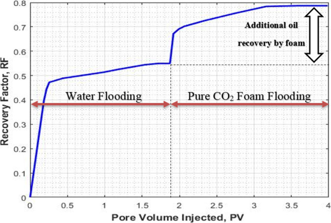
Total recovery factor for the water flooding and pure CO2-foam flooding (expt I).
Figure 4.
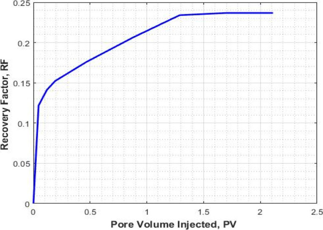
Recovery factor for the pure CO2-foam flooding stage (expt I).
Figure 5.
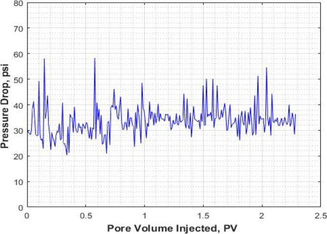
Pressure drop (ΔP) for the pure CO2-foam flooding stage (expt I).
The pressure response and recovery factor for the pure CO2 foam alone are shown in Figures 4 and 5. The average pressure drop around 30 psi can be considered for the pure CO2 foam.
Experiment II (Mixed CO2/N2 Foam)
The results of core flooding with mixed CO2/N2 foam are shown in Figures 6, 7, and 8. In Figure 6, the recovery factor (oil recovery) is plotted against the injected pore volume. Prior to foam flooding, water flooding was conducted by injecting seawater until no more oil was recovered. The recovery factor by water flooding followed by the mixed CO2/N2 foam as a function of injected pore volume is shown in Figure 6. As can be seen that the recovery factor by water flooding is 0.51, the recovery factor by foam flooding followed by water flooding is 0.91. An additional recovery of 0.39 is obtained through mixed CO2/N2 foam flooding as a tertiary recovery method. The ultimate recovery was 0.91.
Figure 6.
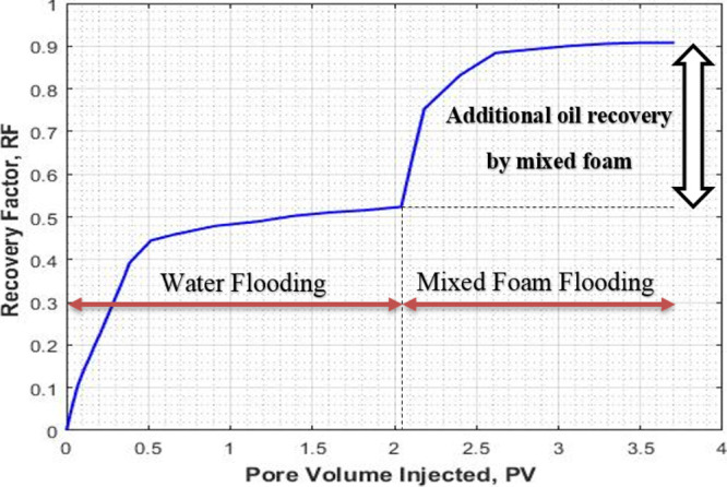
Recovery factor for water flooding and mixed CO2/N2 foam flooding (expt II).
Figure 7.
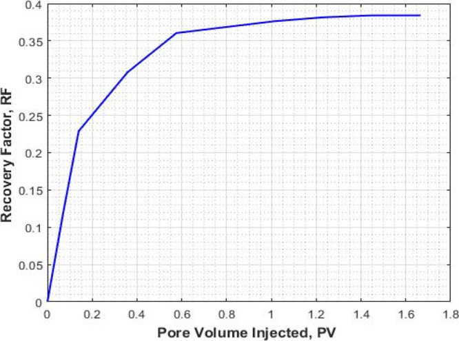
Recovery factor for the mixed CO2/N2 foam flooding (expt II).
Figure 8.
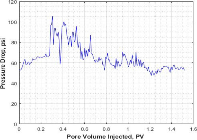
Pressure drop (ΔP) for the mixed CO2/N2 foam flooding (expt II).
The pressure response and recovery factor for the mixed CO2/N2 foam are shown in Figures 7 and 8. The average pressure drop around 60 psi can be considered for the mixed CO2/N2 foam.
Comparison of Pure CO2 Foam and Mixed CO2/N2 Foam
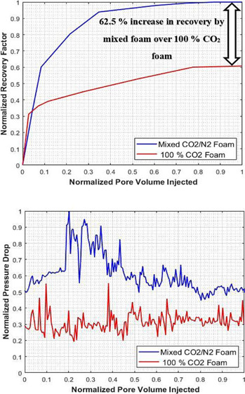
To validate and support the effectiveness of the mixed CO2/N2 foam over the pure CO2 foam, the results of experiment I and II were compared by normalizing the recovery factor, injected pore volume, and pressure drop of the two systems. The normalized recovery factor as a function of the normalized injected pore volume is shown in Figure 9. It can be seen that the recovery factor of the mixed CO2/N2 foam is significantly higher than the pure CO2 foam. CO2/N2 foam flooding recovered an additional oil of original initial oil in place (OIIP), indicating that foam flooding succeeded in producing more oil than the pure CO2 gas foam process. The mixed CO2/N2 foam system can give an incremental recovery of 40% over the pure CO2 foam. Also, the normalized pressure drop vs normalize injected pore volume is shown in Figure 10. It shows that the pressure drop for the mixed CO2/N2 foam is higher than the pure CO2 foam. The high-pressure drop-in mixed CO2/N2 foam is an indication of an increase in apparent viscosity of the foam due to the addition of N2 to the CO2 foam system. The results of the EOR performance of the two systems are summarized in Table 4.
Figure 9.
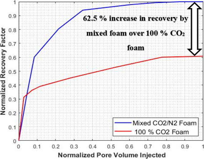
Incremental recovery by mixed CO2/N2 foam over pure CO2 foam.
Figure 10.
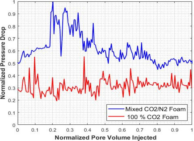
Comparison of pressure drop by mixed CO2/N2 foam and pure CO2 foam.
Table 4. EOR Performance of the Mixed CO2/N2 Foam and Pure CO2 Foam Systema.
| ex-I (pure CO2) | ex-II (mixed CO2/N2) | unit | |
|---|---|---|---|
| total injection rate | 0.50 | 0.50 | cc/min |
| N2 ratio | 0.00 | 0.20 | |
| foam quality | 0.80 | 0.80 | |
| CO2 percent | 100 | 80 | % |
| water flooding recovery | 0.55 | 0.51 | |
| foam flooding recovery | 0.24 | 0.39 | |
| ultimate recovery | 0.78 | 0.91 | |
| normalized recovery | 0.60 | 1.00 |
62.5% increase in recovery by mixed foam over 100% CO2 foam
The concept of adding N2 to CO2 is a novel way of generating CO2 foam at supercritical conditions. Although investigators are trying different ways to generate a strong and stable foam, adding N2 to CO2 can be considered to be the easiest way for foam generation as CO2 always has some impurities in the form of other gases and N2 can be considered as one such gas that helps in generating the foam.
Discussion
The present work shows the solution to CO2-foam generation with the aid of the N2 gas. The inability of generating CO2 foam at or above the supercritical condition of CO2 (1100 psi at 31.1 °C) is due to CO2-gas liquification. However, N2 remains in a subcritical state and generates strong foam even at higher pressures. The hypothesis of the work is based on the nature of the N2 gas which is consider as noncondensable at a pressure generally observed in the hydrocarbon reservoir. A similar phenomenon was observed for steam foam generation due to its condensable nature and addition of N2 gas which is noncondensable at a pressure generally observed in the hydrocarbon reservoir. The foam generation can be improved by the introduction of a noncondensable gas such as N2 which helps in generating the CO2 foam above the supercritical condition of CO2. The improvement in the recovery by mixed CO2/N2 foam is attributed to the strong foam generation due to the addition of the N2 gas. It is evident from the pressure drop observed in the CO2/N2 foam flooding experiment that the CO2/N2 foam is more viscous compared to pure CO2 foam. The high CO2/N2 foam viscosity leads to better mobility control and sweep efficiency and hence the improvement in the oil recovery. However, the detailed mechanism of the foam generation as well as the foam interaction with oil needs further investigation to assert the finding of this work.
Concluding Remarks
In this work, a novel way of generating CO2 foam by replacing part of CO2 with N2 at the supercritical condition of CO2 was investigated. Two different schemes pure CO2 foam and mixed CO2/N2 foam were compared for EOR by using AOS. The EOR performance was evaluated by comparing the incremental recovery of the two systems in terms of the recovery factor and pressure drop.
The analysis of the results obtained through the core flooding experiments can be concluded as follows:
Replacing part of CO2 with N2 generates strong foam at and above the supercritical condition of CO2.
The mixed CO2/N2 foam system has high apparent viscosity compare to the pure CO2 foam leading to an increase in pressure drop; this helps in improving sweep efficiency required for the EOR process.
The mixed CO2/N2 foam system enables the increase of oil recovery by 62.5% over the pure CO2-foam system at and above the supercritical condition of CO2, which is mostly the condition of the hydrocarbon reservoirs.
The increase in recovery is due to high apparent viscosity (indicated by high-pressure drop) associated with mixed CO2/N2 foam over the pure CO2 foam.
Acknowledgments
The authors would like to acknowledge the Deanship of Scientific Research (DSR) at the King Fahd University of Petroleum and Minerals (KFUPM) for funding this research work through the research grant (project # IN171026). The authors would also like to acknowledge the Center of Integrated Petroleum Research (CIPR) at the College of Petroleum Engineering and Geosciences for providing access to their labs for performing the experiments.
Glossary
Nomenclature
- CO2
carbon dioxide
- N2
nitrogen
- Swi
initial water saturation
- Soi
initial oil saturation
Glossary
Abbreviations
- EOR
enhanced oil recovery
- TDS
total dissolved solids
- CCUS
carbon capture, utilization, and storage
- AOS
alpha olefin sulfonate
- CMC
critical micelle concentration
- OIIP
oil initially in place
- HPHT
high-pressure high temperature
- PAM
polymer acrylamide
- HPAM
hydrolyzed poly-acrylamide
- PEF
polymer enhanced foam
- AMPS
2-acrylamido-2-methylpropane sulfonic acid
- NVP
N-vinylpyrrolidones
- PVP
polyvinylpyrrolidones
- AVS
ter-polymer of acrylamide (AM), NVP and AMPS
- PV
pore volume
- RF
recovery factor
- WAG
water alternating gas
- IFT
interfacial tension
The authors declare no competing financial interest.
References
- Zhang P. Y.; Huang S.; Sayegh S.; Zhou X. L.. Effect of CO2 Impurities on Gas-Injection EOR Processes. SPE/DOE Symposium on Improved Oil Recovery; Society of Petroleum Engineers, 2004.
- Holm L. W. CO2 FLOODING–ITS TIME HAS COME. J. Petrol. Technol. 1982, 34, 2739–2745. 10.2118/11592-pa. [DOI] [Google Scholar]
- Whorton L. P., Brownscombe E. R.. Method for Producing Oil by Means of Carbon Dioxide U.S. Patent 2,623,596 A, 1952.
- Li Q.; Chen Z. A.; Zhang J.-T.; Liu L.-C.; Li X. C.; Jia L. Positioning and Revision of CCUS Technology Development in China. Int. J. Greenhouse Gas Control 2016, 46, 282–293. 10.1016/j.ijggc.2015.02.024. [DOI] [Google Scholar]
- Zhang L.; Ren S.; Ren B.; Zhang W.; Guo Q.; Zhang L. Assessment of CO2 Storage Capacity in Oil Reservoirs Associated with Large Lateral/Underlying Aquifers: Case Studies from China. Int. J. Greenhouse Gas Control 2011, 5, 1016–1021. 10.1016/j.ijggc.2011.02.004. [DOI] [Google Scholar]
- Malik Q. M.; Islam M. R.. Potential of Greenhouse Gas Storage and Utilization Through Enhanced Oil Recovery in Canada; World Petroleum Congress, 2000. [Google Scholar]
- Bond D. C.; Holbrook O. C.; Lake C.. Gas drive oil recovery process U.S. Patent 2866507 A, 1958.
- Gauglitz P. A.; Friedmann F.; Kam S. I.; Rossen W. R. Foam Generation in Homogeneous Porous Media. Chem. Eng. Sci. 2002, 57, 4037–4052. 10.1016/s0009-2509(02)00340-8. [DOI] [Google Scholar]
- Schramm L. L.; Wassmuth F.. Foams: Basic Principles, 1994; pp 3–45. [Google Scholar]
- Bian Y.; Penny G.; Sheppard N. C.. Surfactant Formulation Evaluation for Carbon Dioxide Foam Flooding in Heterogeneous Sandstone Reservoirs. SPE–DOE Improved Oil Recovery Symposium Proceedings; Society of Petroleum Engineers, 2012; Vol. 1, pp 626–641.
- Huh C.; Rossen W. R. Approximate Pore-Level Modeling for Apparent Viscosity of Polymer-Enhanced Foam in Porous Media. SPE J. 2008, 13, 17–25. 10.2118/99653-pa. [DOI] [Google Scholar]
- Nguyen P.; Fadaei H.; Sinton D. Pore-Scale Assessment of Nanoparticle-Stabilized CO2 Foam for Enhanced Oil Recovery. Energy Fuel. 2014, 28, 6221–6227. 10.1021/ef5011995. [DOI] [Google Scholar]
- Zhu T.; Ogbe D. O.; Khataniar S. Improving the Foam Performance for Mobility Control and Improved Sweep Efficiency in Gas Flooding. Ind. Eng. Chem. Res. 2004, 43, 4413–4421. 10.1021/ie034021o. [DOI] [Google Scholar]
- Oil & Gas Journal https://www.ogj.com/.
- Patton J. T.; Holbrook S. T.; Hsu W. Rheology Of Mobility-Control Foams. Soc. Petrol. Eng. J. 1983, 23, 456–460. 10.2118/9809-pa. [DOI] [Google Scholar]
- Mast R. F.Microscopic Behavior of Foam in Porous Media. Fall Meeting of the Society of Petroleum Engineers of AIME, FM 1972; Society of Petroleum Engineers, 1972.
- Aarra M. G.; Ormehaug P. A.; Skauge A.; Masalmeh S. K.. Experimental Study of CO2- and Methane-Foam Using Carbonate Core Material at Reservoir Conditions. SPE Middle East Oil and Gas Show and Conference, MEOS, Proceedings; Society of Petroleum Engineers, 2011; Vol. 2, pp 1114–1124.
- Norris S. O.; Scherlin J. M.; Mukherjee J.; Vanderwal P. G.; Abbas S.; Nguyen Q. P.. CO2 Foam Pilot in Salt Creek Field, Natrona County, WY: Phase II: Diagnostic Testing and Initial Results. Proceedings–SPE Annual Technical Conference and Exhibition; Society of Petroleum Engineers (SPE), 2014; Vol. 3, pp 2054–2066.
- Sanders A. W.; Jones R. M.; Linroth M. A.; Nguyen Q. P.. Implementation of a CO2 Foam Pilot Study in the SACROC Field: Performance Evaluation. SPE Annual Technical Conference and Exhibition; Society of Petroleum Engineers, 2012.
- Li Z. Q.; Song X. W.; Wang Q. W.; Zhang L.; Guo P.; Li X. L.. Enhanced Foam Flooding Pilot Test in Chengdong of Shengli Oilfield: Laboratory Experiment and Field Performance. International Petroleum Technology Conference; Society of Petroleum Engineers, 2009; Vol. 3, pp 1536–1549.
- Yu H.; Yang B.; Xu G.; Wang J.; Ren S. R.; Lin W.; Xiao L.; Gao H.. Air Foam Injection for IOR: From Laboratory to Field Implementation in Zhong Yuan Oilfield China. Proceedings–SPE Symposium on Improved Oil Recovery; Society of Petroleum Engineers (SPE), 2008; Vol. 3, pp 1194–1203.
- Buchgraber M.; Castanier L. M.; Kovscek A. R.. Microvisual Investigation of Foam Flow in Ideal Fractures: Role of Fracture Aperture and Surface Roughness. Proceedings - SPE Annual Technical Conference and Exhibition; Society of Petroleum Engineers, 2012; Vol. 3, pp 2288–2304.
- Kovscek A. R.; Tretheway D. C.; Persoff P.; Radke C. J. Foam Flow through a Transparent Rough-Walled Rock Fracture. J. Petrol. Sci. Eng. 1995, 13, 75–86. 10.1016/0920-4105(95)00005-3. [DOI] [Google Scholar]
- Yan W.; Miller C. A.; Hirasaki G. J. Foam Sweep in Fractures for Enhanced Oil Recovery. Colloids Surf., A 2006, 282–283, 348–359. 10.1016/j.colsurfa.2006.02.067. [DOI] [Google Scholar]
- Ferno M. A.; Gauteplass J.; Pancharoen M.; Haugen A.; Graue A.; Kovscek A. R.; Hirasaki G. J.. Experimental Study of Foam Generation, Sweep Efficiency and Flow in a Fracture Network. SPE Annual Technical Conference and Exhibition; Society of Petroleum Engineers, 2014; pp 27–29.
- Elhag A. S.; Chen Y.; Chen H.; Reddy P. P.; Cui L.; Worthen A. J.; Ma K.; Hirasaki G. J.; Nguyen Q. P.; Biswal S. L.; Johnston K. P.. Switchable Amine Surfactants for Stable CO2/Brine Foams in High Temperature, High Salinity Reservoirs. SPE–DOE Improved Oil Recovery Symposium Proceedings; Society of Petroleum Engineers (SPE), 2014; Vol. 1, pp 179–189.
- Farajzadeh R.; Wassing B. M.; Boerrigter P. M. Foam Assisted Gas-Oil Gravity Drainage in Naturally-Fractured Reservoirs. J. Petrol. Sci. Eng. 2012, 94–95, 112–122. 10.1016/j.petrol.2012.06.029. [DOI] [Google Scholar]
- Fernø M. A.; Eide O.; Steinsbø M.; Langlo S. A. W.; Christophersen A.; Skibenes A.; Ydstebø T.; Graue A. Mobility Control during CO2 EOR in Fractured Carbonates Using Foam: Laboratory Evaluation and Numerical Simulations. J. Petrol. Sci. Eng. 2015, 135, 442–451. 10.1016/j.petrol.2015.10.005. [DOI] [Google Scholar]
- Bai B.; Grigg R.; Liu Y.; Zeng Z.-W.. Adsorption Kinetics of Surfactant Used in CO2-Foam Flooding Onto Berea Sandstone. SPE Annual Technical Conference and Exhibition; Society of Petroleum Engineers, 2005; pp 9–12.
- Grigg R. B.; Bai B.. Sorption of Surfactant Used in CO2 Flooding onto Five Minerals and Three Porous Media. SPE International Symposium on Oilfield Chemistry; Society of Petroleum Engineers, 2005.
- Rogers J. D.; Grigg R. B. A Literature Analysis of the WAG Injectivity Abnormalities in the CO2 Process. SPE Reservoir Eval. Eng. 2001, 4, 375–386. 10.2118/73830-pa. [DOI] [Google Scholar]
- Kulkarni M. M.; Rao D. N.. Experimental Investigation of Miscible Secondary Gas Injection. SPE Annual Technical Conference Proceedings; Society of Petroleum Engineers (SPE), 2005; pp 9–12.
- Yin G.; Grigg R. B.; Svec Y.. Oil Recovery and Surfactant Adsorption during CO2-Foam Flooding; Society of Petroleum Engineers (SPE), 2009.
- Farajzadeh R.; Andrianov A.; Bruining H.; Zitha P. L. J. Comparative Study of CO2 and N2 Foams in Porous Media at Low and High Pressure-Temperatures. Ind. Eng. Chem. Res. 2009, 48, 4542–4552. 10.1021/ie801760u. [DOI] [Google Scholar]
- Alkan H.; Goktekin A.; Satman A.. A Laboratory Study of CO2-Foam Process for Bati Raman Field, Turkey. Middle East Oil Show; Society of Petroleum Engineers, 1991.
- Liu Y.; Grigg R. B.; Bai B.. Salinity, PH , and Surfactant Concentration Effects on CO2-Foam. SPE International Symposium on Oilfield Chemistry; Society of Petroleum Engineers, 2005.
- Kapetas L.; Vincent Bonnieu S.; Danelis S.; Rossen W. R.; Farajzadeh R.; Eftekhari A. A.; Mohd Shafian S. R.; Kamarul Bahrim R. Z. Effect of Temperature on Foam Flow in Porous Media. J. Ind. Eng. Chem. 2016, 36, 229–237. 10.1016/j.jiec.2016.02.001. [DOI] [Google Scholar]
- Almajid M. M.; Kovscek A. R. Pore-Level Mechanics of Foam Generation and Coalescence in the Presence of Oil. Adv. Colloid Interface Sci. 2016, 233, 65–82. 10.1016/j.cis.2015.10.008. [DOI] [PubMed] [Google Scholar]
- Mannhardt K.; Novosad J. J.; Schramm L. L.. Foam/Oil Interations at Reservoir Conditions. SPE/DOE Improved Oil Recovery Symposium; Society of Petroleum Engineers, 1998.
- Xu X.; Saeedi A.; Liu K. Laboratory Studies on CO2 Foam Flooding Enhanced by a Novel Amphiphilic Ter-Polymer. J. Petrol. Sci. Eng. 2016, 138, 153–159. 10.1016/j.petrol.2015.10.025. [DOI] [Google Scholar]
- Dong X.; Liu H.; Hou J.; Liu G.; Chen Z.. Polymer-Enhanced Foam PEF Injection Technique to Enhance the Oil Recovery for the Post Polymer-Flooding Reservoir. SPE Western Regional Meeting Proceedings; Society of Petroleum Engineers (SPE), 2016.
- Lande S.Polymer Enhanced Foam in Unconsolidated Sand, 2016. [Google Scholar]
- Sydansk R. D. Polymer-Enhanced Foams Part 1: Laboratory Development and Evaluation. SPE Adv. Technol. 1994, 2, 150–159. 10.2118/25168-pa. [DOI] [Google Scholar]
- Azdarpour A.; Rahmani O.; Rafati R.; Hamidi H., Laboratory Investigation of the Effects of Parameters Controlling Polymer Enhanced Foam (PEF) Stability. Asian J. Appl. Sci., 1, 2013. [Google Scholar]
- Perttamo E. K.Characterization of Associating Polymer; AP Solutions, 2013. [Google Scholar]
- Shen C.; Nguyen Q. P.; Huh C.; Rossen W. R.. Does Polymer Stabilize Foam in Porous Media?. SPE/DOE Symposium on Improved Oil Recovery; Society of Petroleum Engineers, 2006.
- Sydansk R. D. Polymer-Enhanced Foams Part 2: Propagation Through High-Permeability Sandpacks. SPE Adv. Technol. 1994, 2, 160–166. 10.2118/25175-pa. [DOI] [Google Scholar]
- Pu W.; Wei P.; Sun L.; Wang S. Stability, CO2 Sensitivity, Oil Tolerance and Displacement Efficiency of Polymer Enhanced Foam. RSC Adv. 2017, 7, 6251–6258. 10.1039/c6ra27063h. [DOI] [Google Scholar]
- Ahmed S.; Elraies K. A.; Tan I. M.; Hashmet M. R. Experimental Investigation of Associative Polymer Performance for CO2 Foam Enhanced Oil Recovery. J. Petrol. Sci. Eng. 2017, 157, 971–979. 10.1016/j.petrol.2017.08.018. [DOI] [Google Scholar]
- Li D.; Ren S.; Zhang P.; Zhang L.; Feng Y.; Jing Y. CO2-Sensitive and Self-Enhanced Foams for Mobility Control during CO2 Injection for Improved Oil Recovery and Geo-Storage. Chem. Eng. Res. Des. 2017, 120, 113–120. 10.1016/j.cherd.2017.02.010. [DOI] [Google Scholar]
- Sun Q.; Li Z.; Li S.; Jiang L.; Wang J.; Wang P. Utilization of Surfactant-Stabilized Foam for Enhanced Oil Recovery by Adding Nanoparticles. Energy Fuel. 2014, 28, 2384–2394. 10.1021/ef402453b. [DOI] [Google Scholar]
- Konwar R.; Ahmed A. B. Nanoparticle: An Overview of Preparation, Characterization and Application. Int. Res. J. Pharm. 2013, 4, 47–57. 10.7897/2230-8407.04408. [DOI] [Google Scholar]
- Llave F. M.; Chung F. .-H.; Louvier R. W.; Hudgins D. A.. Foams as Mobility Control Agents for Oil Recovery by Gas Displacement. SPE/DOE Enhanced Oil Recovery Symposium; Society of Petroleum Engineers, 1990.
- Osei-Bonsu K.; Shokri N.; Grassia P. Fundamental Investigation of Foam Flow in a Liquid-Filled Hele-Shaw Cell. J. Colloid Interface Sci. 2016, 462, 288–296. 10.1016/j.jcis.2015.10.017. [DOI] [PubMed] [Google Scholar]
- Harris P. C. DYNAMIC FLUID-LOSS CHARACTERISTICS OF CO2-FOAM FRACTURING FLUIDS. SPE Prod. Eng. 1987, 2, 89–94. 10.2118/13180-pa. [DOI] [Google Scholar]
- Du D.-X.; Beni A. N.; Farajzadeh R.; Zitha P. L. J. Effect of Water Solubility on Carbon Dioxide Foam Flow in Porous Media: An X-Ray Computed Tomography Study. Ind. Eng. Chem. Res. 2008, 47, 6298–6306. 10.1021/ie701688j. [DOI] [Google Scholar]
- Nguyen T. A.; Farouq Ali S. M. Effect of Nitrogen on the Solubility and Diffusivity of Carbon Dioxide into Oil and Oil Recovery by the Immiscible WAG Process. J. Can. Pet. Technol. 1998, 37, 24–31. 10.2118/98-02-02. [DOI] [Google Scholar]
- Harris P. C. Comparison of Mixed-Gas Foams with N2 and CO2 Foam Fracturing Fluids on a Flow-Loop Viscometer. SPE Prod. Facil. 1995, 10, 197–203. 10.2118/20642-pa. [DOI] [Google Scholar]
- Rossen W. R.Foams in Enhanced Oil Recovery. Foams: Theory, Measurements, Applications, 1996; pp 413–464. [Google Scholar]
- Chabert M.; Morvan M.; Nabzar L.. Advanced Screening Technologies for the Selection of Dense CO2 Foaming. SPE Improved Oil Recovery Symposium; Society of Petroleum Engineers, 2012; pp 14–18.
- Kibodeaux K.Experimental and Theoretical Studies of Foam Mechanisms in Enhanced Oil Recovery and Matrix Acidization Applications, 1999. [Google Scholar]
- Siddiqui M. A. Q.; Gajbhiye R. Stability and Texture of CO2/N2 in Sandstone. Colloids Surf., A 2017, 534, 26–37. 10.1016/j.colsurfa.2017.04.049. [DOI] [Google Scholar]