Abstract
Objectives:
Mechanical damages can occur from dental restoration processing and fitting, or while it is in-service. This study evaluates the damage sensitivity of translucent zirconia (5Y-PSZ) relative to conventional 3Y-PSZ following mouth-motion simulations at varying loads.
Methods:
5Y-PSZ and 3Y-PSZ discs were adhesively bonded to a dentin-like substrate and divided into groups according to the load (50 N or 200 N) and number of cycles (up to 106) used in the chewing simulation. Specimens were mounted with 30° inclination in an electrodynamic mouth-motion simulator, and subjected to contact-slide-liftoff cyclic loading in water. Surface and sub-surface damages were analyzed using a sectioning technique. After the simulation, specimens were removed from the substrate and loaded with the damaged surface in tension for biaxial strength testing to assess their damage tolerance.
Results:
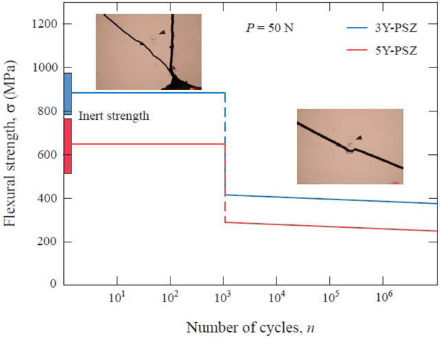
The strength of both ceramics underwent significant degradation after mouth-motion simulations. For 5Y-PSZ, the strength degradation was greater (~60%) and occurred at a lower number of cycles than 3Y-PSZ. Herringbone cracks emerged on 3Y-PSZ and 5Y-PSZ surfaces under a 200-N load after 50 and 10 cycles, respectively. Meanwhile at a 50-N load, cracks formed at ~1,000 cycles in both ceramics. Further increasing the number of cycles only had moderate effects on the strength of both ceramics, despite an increase in surface and sub-surface damage. More significantly, a 50-N occlusal load can debase the zirconia strengths as much as a 200-N load.
Significance:
Surface flaws produced during the chewing simulation are capable of significant strength degradation in zirconia, even after a small number of low-load cycles.
Keywords: ceramics, prostheses, mechanical damage, strength degradation, sliding contact, occlusion
Graphical Abstract
1. Introduction
Fabricating and inserting all-ceramic dental restorations involve several steps that have the potential of causing damages. Flaws can be introduced to the ceramic from CAD-CAM (computer-aided design – computer-aided manufacturing) milling, sintering process, surface treatments to improve bonding, inner and occlusal adjustments with rotatory instruments, and finishing procedures [1, 2]. Additionally, in-service conditions are aggressive. The restoration should withstand a humid environment with varying temperatures and pH levels. The materials are also susceptible to mechanical damages from attrition against the antagonist crown and from abrasion during chewing and tooth brushing [3–5].
Three mol% yttria partially stabilized zirconia (3Y-PSZ) has been widely used to produce all-ceramic crowns and fixed partial dentures (FPD) in both bilayer and monolithic configurations due to its great mechanical properties [6–9]. Traditionally, this class of zirconia has been referred to as tetragonal zirconia polycrystals (3Y-TZP), since the original 3Y-TZP material, which often consists of 0.25 wt% alumina sintering additives, is typically sintered at 1350 – 1450 °C. The final product contains ~90 – 94 wt% tetragonal zirconia. However, most of the 3Y partially stabilized zirconias used in dentistry do not contain alumina additives and thus they are commonly sintered at 1500 – 1550 °C in order to achieve a good density for better translucency [10]. The higher sintering temperature produces higher amount of cubic zirconia (up to ~30 wt% c-ZrO2). Thus, dental 3Y zirconia is precisely a 3Y-PSZ.
The reported survival rates for zirconia-based restorations vary among clinical studies [11–14], suggesting that 3Y-PSZ is not immune to failure. Catastrophic fracture of 3Y-PSZ has been attributed to defects introduced from restoration fabrication and installation, while chipping is also associated with damage from occlusal wear [15, 16]. Therefore, refinements in ceramic processing and finishing to produce more homogeneous materials may not guarantee the longevity of the restorations; ceramics should show high damage tolerance in order to survive all these clinical challenges [1, 2].
More recently, in order to seek for more translucent materials to fabricate monolithic restorations, several variants of dental zirconias have been developed: namely 4 mol% and 5 mol% partially stabilized zirconia (4Y-PSZ and 5Y-PSZ) [17]. Due to higher amounts of yttria stabilizer, 4Y-PSZ and 5Y-PSZ have higher contents of cubic zirconia, resulting in greater translucency, but also lower fracture strength and toughness relative to 3Y-TZP [17]. The mechanical properties of these ceramics are affected by a coarser grain size coupled with the lack of phase transformation toughening ability of cubic zirconia [18–21]. Yet, other properties such as hardness and elastic modulus are in the same range as 3Y-PSZ [17, 21]. Because of the newness of these cubic-containing zirconias, very few clinical studies exist in the dental literature. Therefore, the effect of compositional and microstructural modifications on the long-term structural stability of translucent zirconia remains elusive. Moreover, the damage tolerance of these materials in a scenario that simulates occlusion has not been studied.
Occlusion is a complex phenomenon [22]. However, posterior occlusal contacts can be visualized as a supporting cusp in contact with the tip of a triangular ridge, continuing the sliding contact until a centric stop on the opposing tooth is reached [23]. The radius of a cusp tip is several millimeters [24], whereas that of the opposing cusp ridge is on the order of 100 mm [25]. Thus, the sliding path can be approximated as a straight-line motion of ~0.5 mm in length [26]. A similar cusp on flat surface sliding contact occurs in the anterior region, but this time the sliding distance is slightly longer, around 0.5 – 1.2 mm. The magnitude of occlusal load varies from 5 to 364 N [27], while the loading phase typically lasts for 0.25 to 0.33 sec [28].
It has been long-established that when a blunt indenter is pressed against a brittle surface and slides across, a series of partial cone cracks may form at the trailing edge of the moving indenter [29]. Due to friction between the indenter (cusp tip) and brittle surface (cusp ridge), tensile stress intensifies at the trailing edge of the indenter [30, 31]. Thereby, the occlusal load needed to generate partial cone cracks is significantly reduced relative to frictionless axial loading [32]. In addition, in the presence of oral fluid, repeated sliding contact can force the fluid into the crack tips, creating a hydraulic pumping effect [26, 33]. Such mechanical fatigue in conjunction to chemically-assisted ‘slow crack growth’ (SCG) can drive partial cone cracks deep into the material with relatively short time spans [3]. The question then arises as to what extent these deep penetrating partial cone cracks can compromise the strength of brittle materials. Accordingly, this study aims to investigate the damage sensitivity of a translucent zirconia (5Y-PSZ) in comparison to a conventional 3Y-PSZ following mouth-motion simulations under different occlusal loads (50 N and 200 N) as well as to characterize the surface and sub-surface damage introduced to the materials.
2. Theory
A complete contact mechanics analysis concerning the initiation and propagation of partial cone cracks (or simply, herringbone or horseshoe cracks) has been performed previously [32, 34]. The focus of the present study is the implications of partial cone crack on strength degradation in brittle material.
Consider partial cone cracks initiated from surface flaws in a brittle plate and loaded in tension, fracture occurs when:
| (1) |
where σF is the stress at fracture, KIc is the mode I critical stress intensity factor or fracture toughness, cF is the critical flaw size, and Y is a dimensionless stress intensity shape factor that takes into account the shape of the critical flaw and the loading conditions.
Since the critical flaw is located in the crack mouth of a partial cone and at the specimen surface, its growth relation under cyclic sliding contact is given by [35]:
| (2) |
where cI is the initial flaw size, n is the number of cycles, and N is the velocity exponent for SCG.
By combining Eqs. (1) and (2), Eq. (3) is obtained:
| (3) |
where is the first strength drop for a predetermined cyclic load.
3. Experiments
3.1. Materials and specimens
Two types of ceramics were investigated: a translucent 5 mol% yttria-partially-stabilized-zirconia (5Y-PSZ, Zpex Smile, Tosoh Corporation, Tokyo, Japan) and a control 3 mol% yttria-partially-stabilized tetragonal zirconia (3Y-PSZ, Zpex, Tosoh Corporation, Tokyo, Japan). Zirconia discs were prepared by cutting pre-sintered CAD-CAM rods using a diamond blade in a low speed cutting machine, with water cooling (Isomet Low Speed Saw, Buehler, Lake bluff, IL). Pre-sintered discs were ground using a sequence of silicon-carbide abrasive paper (MicroCut S Discs #320, #800, #1200, #1400 grit size, Buehler, Lake bluff, IL, USA) and sintered, according to the manufacturer recommendations. 3Y-PSZ was sintered at 1530 °C and 5Y-PSZ was sintered at 1450 °C for 2 hours in an air atmosphere box furnace (Lindberg/Blue M, Thermo Scientific, Mansfield, TX). One flat surface of the sintered zirconia discs was polished down to 1 μm finish using a polishing machine (Ecomet 4, Buehler, Lake bluff, IL, USA). The final dimensions of the polished discs had a 1.2 mm thickness and 13.7 mm diameter.
The microstructure was observed on polished and thermally etched samples by scanning electron microscopy (SEM, Merlin, Carl Zeiss AG, Oberkochen, Germany). To prevent potential grain growth, thermal etching was carried out at 1250 °C for 20 min with a fast heating rate of 20 °C/min. For grain size determination, a minimum of 500 grains from at least 3 SEM images of different specimens were measured. The linear intercept method [36] with a correction factor of 1.56 for tetrakaidecahedral grains was utilized [37].
The crystalline phases of 3Y-PSZ and 5Y-PSZ were identified by x-ray diffraction (XRD, PANalytical X’Pert, Malvern Panalytical Ltd, Malvern, UK) with nickel-filtered Cu Kα radiation, operating at 45 kV and 40 mA. Scans were performed over the 2θ range 25° – 80° at a scan rate of 0.2°/min and a step size of 0.02°. Phase analysis was carried out using the Highscore Plus for Rietveld refinement (Malvern Panalytical Ltd, Malvern, UK).
The polished zirconia discs were bonded onto a dentin-like composite substrate (glass-fiber-reinforced epoxy resin; NEMA G10, International Paper, Memphis, TN) with a resin cement (Panavia F 2.0, Kuraray Noritake Dental Inc., Tokyo, Japan). Before cementation, one surface of the ceramic disc was air-abraded with 50 μm alumina particles at 3 bars pressure for 20 s, followed by ultrasonic cleaning with water and air-drying. G10 substrate was stored in distilled water at 37 °C for 3 weeks to allow hygroscopic expansion [23]. Then, G10 surface was acid etched with 4.5% hydrofluoric acid (Etching Gel, Ivoclar Vivadent AG, Schaan, Liechtenstein) for 2 min, rinsed with water and air-dried. Clearfil Ceramic Primer Plus (Kuraray Noritake Dental Inc., Tokyo, Japan) was applied to the ceramic and G10 cementation surfaces using a microbrush for 60 s and air-dried. Afterwards, resin cement was mixed and applied to the treated ceramic surface, which was placed onto the G10 surface. Excess cement was removed with a microbrush and a 9.8 N load (0.067 MPa stress) was applied to the ceramic surface for 2 min in order to obtain a uniform cement layer. Each side of the ceramic disc was light-cured (Bluephase Style, Ivoclar Vivadent AG, Schaan, Liechtenstein) for 20 s. Finally, specimens were stored in distilled water at 37° C for 5 days prior to the mouth-motion simulation.
3.2. Testing and characterization
Specimens were subjected to contact-slide-liftoff mouth-motion cyclic loading using an electrodynamic fatigue testing machine (EnduraTEC ELF 3300, TA Instrument, Minnetonka, MN, USA) (Fig. 1a) [38]. The load was applied onto the center of the ceramic disc through a spherical 3Y-TZP antagonist (r = 3.15 mm, surface roughness Ra = 0.254 μm [5]) at a 1000 N/s loading rate (~2 Hz) in distilled water. Specimens were placed with 30° inclination in the fatigue machine as to facilitate off-axis loading of the antagonist. The test was performed as follows: (1) the antagonist contacts the ceramic surface and the maximum load is transferred while sliding down the tilted surface for, approximately, 1 mm; (2) the antagonist lifts out of contact while returning to its original position, to begin a new cycle [5]. Two load levels that are near the 2 extremes of the nominal masticatory force range were used in the mouth-motion simulation, 50 N and 200 N. Ten different durations of cyclic loading were evaluated: n = 2, 5, 10, 50, 102, 103, 104, 105, and 106 cycles. A minimum of 4 specimens were tested for any given number of cycles. A new antagonist was used for each specimen.
Figure 1.
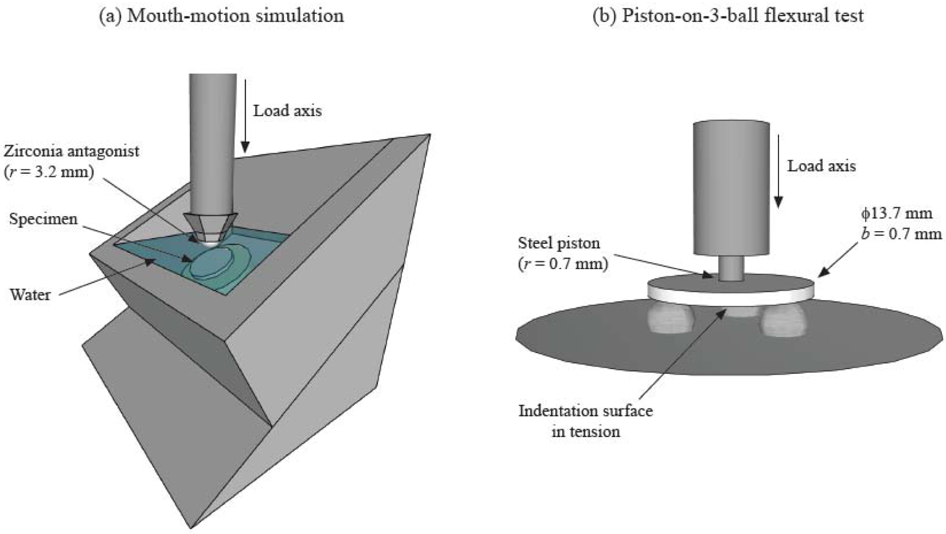
Experimental set-up for the mouth-motion simulation and the piston-on-three-balls flexural test.
After the simulations, ceramic specimens were removed from the G10 substrate using a diamond blade in a low speed cutting machine under water irrigation. A thin layer of remaining G10 material was manually peeled off the specimen surface. Specimens were tested for biaxial flexural strength to access their damage tolerance (Fig. 1b). Discs were tested with piston-on-three-balls using a universal testing machine (Instron series 5566, Instron Worldwide Headquarters, Norwood, MA, USA) with 1 mm/min crosshead speed. The test was performed with the specimen’s damaged surface loaded in tension. For each ceramic material, 12 discs that were not subjected to the fatigue test were also tested to obtain the initial flexural strength. Biaxial flexural strength σ (MPa) was calculated using ISO/FDIS 6872:2014(E) equations:
where P is the load at fracture (N), υ is the Poisson’s ratio (= 0.315 for zirconia) [39], r1 is the support ball radius (= 5 mm), r2 is the radius of the piston tip (= 0.7 mm), r3 is the specimen radius (mm), and b is the specimen thickness (mm).
3.3. Microscopy and analysis
Surface and cross-sectional images were obtained to characterize surface and sub-surface damage induced from the different mouth-motion simulations. To investigate the sub-surface damage, specimens were embedded in epoxy resin and sectioned along the direction of the sliding contact using a diamond blade in a cutting machine, with water cooling (Isomet Low Speed Saw, Buehler). Then, the cross-sections were polished with a 1 μm diamond suspension finish, and analyzed in the SEM.
Fracture surfaces were analyzed using an optical microscope (Nikon LV150, Tokyo, Japan) and a SEM to identify fractographic features of crack propagation and to locate the critical flaw.
All SEM studies were conducted using an environmental scanning electron microscope (EVO 50, Carl Zeiss AG, Oberkochen, Germany). Specimens were analyzed without a conductive coating in low vacuum. Images were obtained at 10.5 mm working distance, 15 kV accelerating voltage, 500 pA probe current, and 99 Pa chamber pressure.
3.4. Statistical analysis
Flexural strength data of the control groups passed the Shapiro-Wilk Normality test (p = 0.972) and the Equal Variance test (p = 0.528), and were statistically analyzed using t-test (α = 0.05).
4. Results
4.1. Material composition and properties
Figure 2 shows the SEM images of polished and thermally etched zirconia specimens: (a) 3Y-PSZ and (b) 5Y-PSZ. The average grain size, according to the linear intercept method, was 0.54 ± 0.04 μm for 3Y-PSZ and 1.33 ± 0.06 μm for 5Y-PSZ. Rietveld refinement on XRD spectra revealed that 3Y-PSZ consists of 29% c-ZrO2 and 71% t-ZrO2 (Rwp = 5.12, χ2 = 9.54), whereas 5Y-PSZ is composed of 69% c-ZrO2 and 31% t-ZrO2 (Rwp = 5.17, χ2 = 1.95). For the structured XRD refer to previous publication [18].
Figure 2.
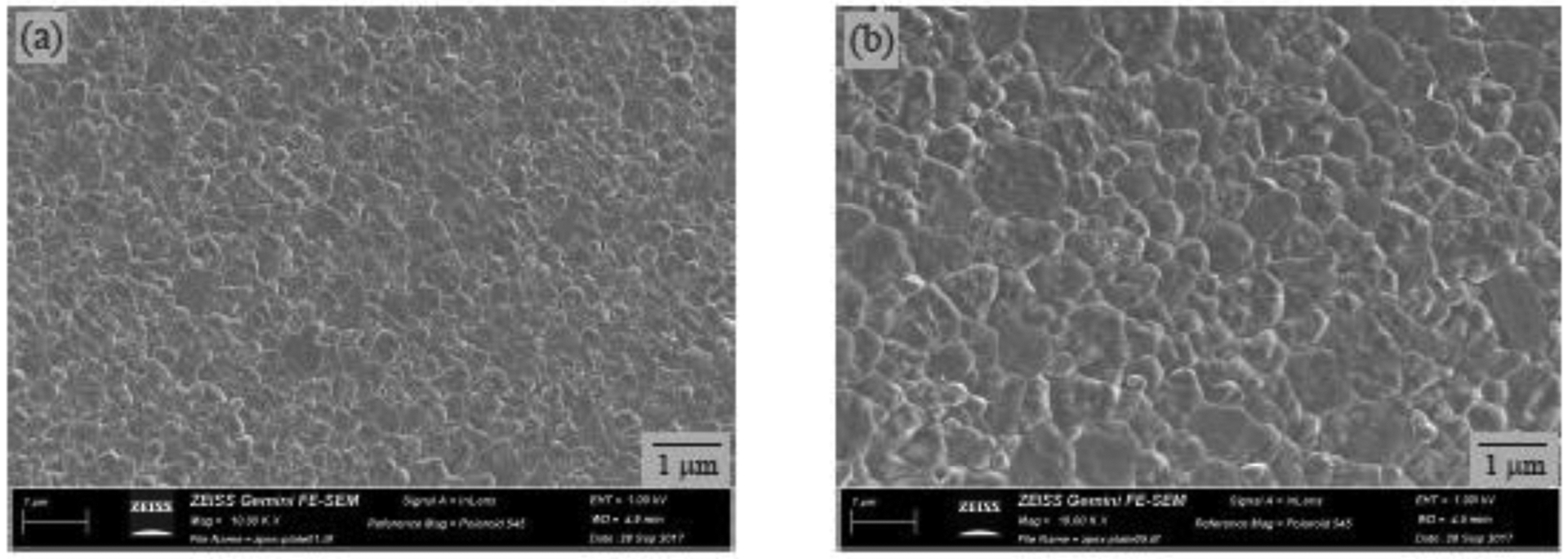
Scanning electron micrographs of microstructures for zirconia materials tested: (a) 3Y-PSZ and (b) 5Y-PSZ. Note specimen surfaces were polished and thermally etched.
The mechanical properties of the yttria-stabilized zirconia materials used in the present study are shown in Table 1. The mean initial strength of the 3Y-PSZ group was statistically higher than that of 5Y-PSZ (p < 0.001).
Table 1.
Mechanical properties of the studied materials. Mean flexural strength (σF), Vickers hardness (HV), fracture toughness (KIc) and respective standard deviation values (SD).
| Material | σF ± SD (MPa)* | HV ± SD (GPa) | KIc (MPa.m1/2)** |
|---|---|---|---|
| 3Y-PSZ | 878 ± 97a | 13.6 ± 0.8 | 5.0 |
| 5Y-PSZ | 641 ± 132b | 13.8 ± 0.1 | 2.4 |
Mean values followed by different letters in the same column are statistically different (p<0.05).
KIc values provided by the manufacturer (Tosoh).
4.2. Sliding contact fatigue and truncated cone morphology
Figure 3 shows representative images of 3Y-PSZ and 5Y-PSZ surface after 200 N cyclic loading for 102 and 105 cycles. In the beginning of the mouth-motion simulation, small partial cone cracks emerged at the trailing edge of the sliding indenter in both ceramics (Figs. 3a and b). As the number of cycles increased, a wear crater started to form. Within these wear craters, a higher density of herringbone cracks was observed accompanied by a smeared zirconia layer with micro pitting and spalling due to the crushing of wear debris and fragments [40, 41]. Subsequently, cracks started to form in the leading edge of the crater as a result of compressive stresses ahead of the moving antagonist [42] (Figs. 3c and d). In addition, the wear crater appeared to be slightly lager in 5Y-PSZ than 3Y-PSZ, even more so following longer duration testing (n > 105).
Figure 3.
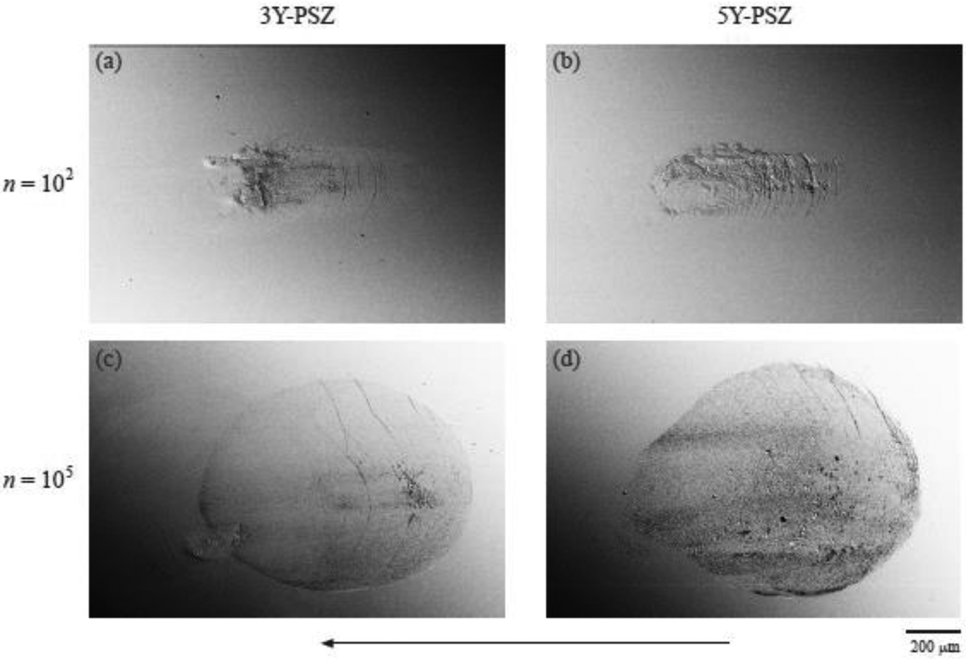
Micrographs showing the surface damage caused by 200 N simulated occlusal loading in 3Y-PSZ (a & b) and 5Y-PSZ (c & d) after 102 and 105 cycles. Sliding direction is from right to left. Images were obtained with a backscattered electron detector (BSD, EHT 15 kV, and chamber pressure 99 Pa).
Figure 4 shows representative SEM images taken from both (a, b) top and (c, d) section views of 5Y-PSZ and 3Y-PSZ following sliding contact at 200 N for n = 104 and 106 cycles, respectively. Sectional views across the contact damage in the direction parallel to the sliding direction showed surface ring cracks propagating down to form partial cone cracks in both ceramics (Figs. 4c and d). For 5Y-PSZ (Fig. 4c), a larger density of lateral cracks was observed, leading to the dislodgement of zirconia grains (micropitting) and thus resulting in a rougher surface than 3Y-PSZ (Fig. 4d). In addition, it is interesting to note that 5Y-PSZ tested for only 104 cycles sustained comparable sub-surface damage to that observed in 3Y-PSZ tested for 106 cycles.
Figure 4.
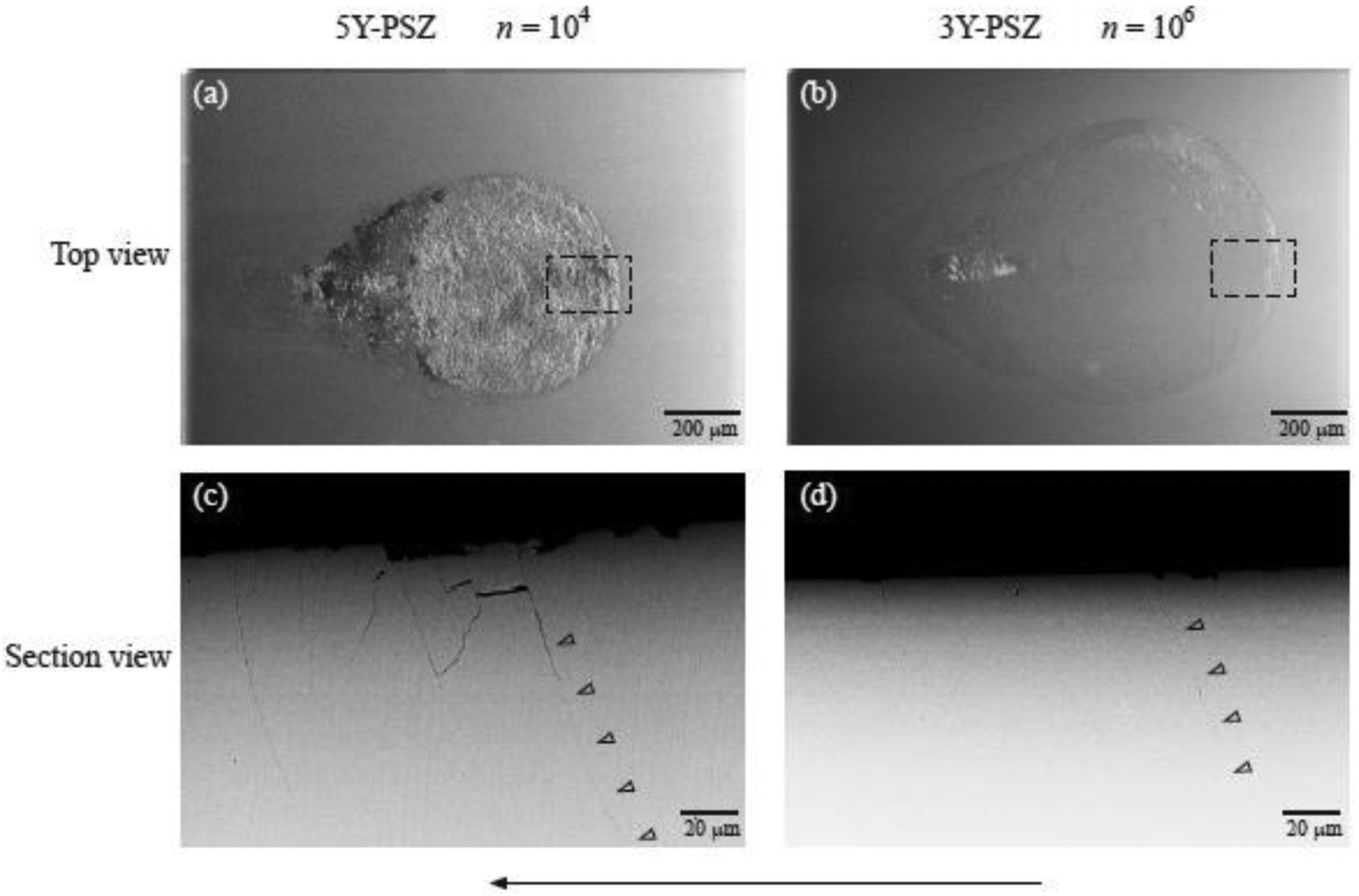
Surface and sectional views of damage sustained in 5Y-PSZ and 3Y-PSZ following mouth-motion simulation at P = 200 N for n = 104 and 106 cycles, respectively. Surface views of the wear scars in (a) 5Y-PSZ and (b) 3Y-PSZ. Cross-sectional views of the area delimited by the dashed box showing partial cone cracks propagating from the surface to the interior of (c) 5Y-PSZ and (d) 3Y-PSZ. Note arrows in (c) and (d) highlight the trajectory of partial cone cracks. Sliding direction is from right to left. Images (a) and (b) were obtained with a pressure secondary electron detector (VPSE), whereas (c) and (d) were taken with a BSD (EHT 15 kV, and chamber pressure 99 Pa).
After the mouth-motion simulation, the zirconia antagonists were also analyzed using an optical microscope. Very small and shallow wear scars were found.
4.3. Strength degradation and fractographic analysis
The strength of both ceramics underwent significant degradation after mouth-motion simulations (Fig. 5). When the mouth-motion simulation was performed with a 200-N load, the mean flexural strength of 75% of 3Y-PSZ specimens decreased from 878 MPa (initial) to 410 MPa (~50%) after 50 cycles of contact (Fig. 5a). For 5Y-PSZ, the dropoff in strength was greater (~60%) and occurred with an even lower number of cycles. 30% of 5Y-PSZ specimens showed strength degradation after only 10 cycles and 60% after 50 cycles. The decline lines in Fig. 5a are predictions in accordance with strength degradation from moisture-assisted SCG acting on critical flaws (Eq. 3), with N = 32 for zirconia [43]. When a 50-N load was used in the occlusal contact simulation, both 3Y-PSZ and 5Y-PSZ showed strength degradation between 750 and 1,000 cycles (Fig. 5b). However, a higher percentage of 5Y-PSZ specimens (90%) started to degrade in this range of contact cycles than 3Y-PSZ (60%). Again, the decline lines are strength degradation data that fits to a dependence using Eq. 3. To demonstrate the strength degradation thresholds for both materials subject to high (P = 200 N) and low (P = 50 N) occlusal loads, Fig. 5c condenses the plots from Figs. 5a and b onto a master diagram. It becomes apparent that once strength degradation occurred, the magnitude of dropoff is similar for zirconia subject to 200 N or 50 N loads. In addition, further increasing the number of loading cycles (up to 1 million) for both loads had no significant effect on the flexural strength of both ceramics, despite a marked increase in the surface and sub-surface damage and its associated wear crater dimensions and partial cone crack size (Figs. 3 and 4). Nevertheless, 3Y-PSZ, the stronger and tougher material of the two, exhibited a better resistance to sliding contact damage.
Figure 5.
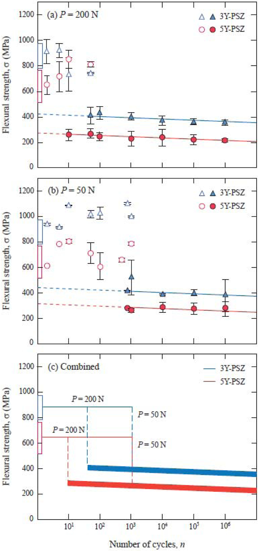
The remaining strength σ as a function of number of sliding contact cycles n, indentation with a zirconia sphere of radius r = 3.15 mm, at maximum loads P indicated: (a) 3Y-PSZ in water; (b) 5Y-PSZ in water; and (c) combined strength degradation plots. Data points are means and standard deviations, minimum four specimens per point. Filled symbols indicate failure from indentation sites. Unfilled symbols indicate failure from natural flaws. Box at left axis and horizontal solid line are “laboratory” strengths (unindented specimens). Solid curves are theoretical fits to data using Eq. 3.
Post-mortem fractographic analysis revealed that specimens without strength degradation failed from natural flaws, away from the sliding contact damage (Fig. 6a), while specimens with reduced strength failed from the sliding contact sites (Figs. 6b – f). At a P = 50 N load, herringbone cracks emerged on 5Y-PSZ and 3Y-PSZ surfaces at n ~ 103. Fig. 6a shows one of the 5Y-PSZ samples that did not exhibit strength degradation after n = 103 sliding contact. As presented, fracture occurred away from the indentation site. However, for n > 103, all specimens exhibited dropoff in strength while failed from the indentation sites. At a P = 200 N load, surface herringbone cracks were present in 5Y-PSZ following merely 10 cycles of sliding (Fig. 6d), and failure originated from the contact damage area. These strength dropoff thresholds are in agreement with the strength σ as a function of sliding cycles n shown in Fig. 5.
Figure 6.
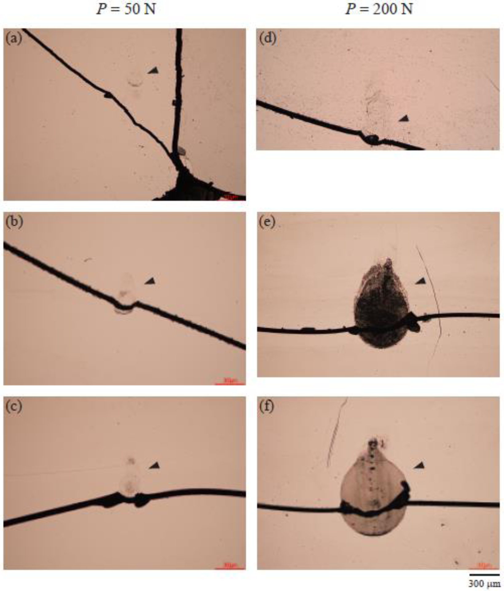
Optical microscope images of the fracture surface of 5Y-PSZ subjected to the biaxial flexural strength test after mouth-motion simulations at various contact loads and sliding cycles. At a P = 50 N occlusal load: (a) n = 103, (b) n = 104, and (c) n = 105 cycles. At a P = 200 N occlusal load: (d) n = 10, (e) n = 104, and (f) n = 105 cycles. Note arrows indicate the sliding contact sites. Sliding direction is from bottom to top.
Figure 7 shows the fracture behavior of 3Y-PSZ subject to sliding contact at P = 200 N for various number of cycles. Here, we show both surface view to illustrate the fracture–indentation site relationship (Figs. 7a, e, i, m, and q), as well as detailed fractographic analysis to elucidate the fracture origin and strength limiting flaws. As can be seen, at n = 10 cycles, fracture almost exclusively initiated from nature flaws (Figs. 7a–d). However, for n = 50 and beyond, fractures all involved partial cone cracks and initiated from flaws within the original cone (Fig. 7e–t). More importantly, despite an increased damage zone coupled with larger and deeper partial cone cracks as the number of sliding cycles increased, the flaws at the fracture origins exhibited very little change in size (Figs. 7h, i, p, and t).
Figure 7.

Optical and SEM images of the fracture surface of 3Y-PSZ subjected to the biaxial flexural strength test after mouth-motion simulations at P = 200 N for various sliding cycles. (a), (e), (i), (m), and (q): optical microscope images of the fracture surface. The rest of the figures are SEM images of fractured surface at a consecutive series of magnifications, which illustrate the fracture origin and fracture origin flaws (indicated by arrows in Figs. d, h, l, p, and t).
5. Discussion
This work has investigated the damage tolerance of two types of dental zirconia ceramics: a translucent 5Y-PSZ and a conventional 3Y-PSZ. Translucent 5Y-PSZ possesses inferior mechanical behavior relative to 3Y-PSZ, meaning lower flexural strength and fracture toughness and higher susceptibility to strength degradation after simulated occlusal contact. These results are mainly related to the compositional and microstructural differences between the two ceramics. 5Y-PSZ is stabilized with 5 mol% of yttria, resulting in ~70 wt% of cubic zirconia, while 3Y-PSZ is doped with 3 mol% of yttria, leading to a lower cubic content (~30 wt%). It is evident that 5Y-PSZ is not a fully stabilized zirconia, since it still consists of ~30 wt% metastable tetragonal zirconia. Increasing the optically isotropic cubic content can improve the zirconia translucency but decrease the fracture strength and toughness as the tetragonal-to-monoclinic transformation toughening mechanism is compromised. Additionally, 5Y-PSZ has a larger grain size than 3Y-PSZ due to the higher cubic content [18, 21], which in turn also yields a better translucency but lower strength.
Determining the remaining flexural strength of monolithic specimens after simulated occlusal contact can provide useful insight into the effect of sliding contact damage on the mechanical behavior of the ceramics. The strength degradation plots in Fig. 5 constructively quantify the susceptibility of dental zirconias to sliding contact fatigue, thereby providing a basis for material evaluation using clinically relevant testing procedures. Two thresholds can be identified for each ceramic according to the loading conditions, high (P = 200 N) or low (P = 50 N) load (Fig. 5). Below the threshold, cone cracks do not initiate and the material’s natural flaw population controls its strength, as observed in Figs. 6a and 7a–d. Above the threshold, cracks emerged in the ceramics followed by significant strength degradation. Damage modes responsible for strength degradation are described in detail below.
Previous studies have investigated contact damage modes and strength degradation of zirconia (3Y-TZP), alumina, glass-infiltrated ceramics, and porcelain after cyclic contact in axial loading at the occlusal surface from a tungsten carbide sphere of radius r = 3.18 mm [44, 45]. Compared to other tested dental ceramics, 3Y-TZP exhibited superior damage resistance, and strength degradation did not occur until n = 106 cycles at a whopping load of P = 1000 N [45]. Under axial fatigue loading in water, there are 3 distinct damage modes responsible for strength degradation of 3Y-TZP. They are classical outer cone fracture, deleterious inner cone fracture, and quasi-plastic deformation [35]. Due to the superior mechanical properties of 3Y-TZP, none of these damage modes are well-developed until n = 106 cycles at P = 1000 N load. Thus, 3Y-TZP is ‘immune’ to contact damage under axial loading. However, chewing involves complex mouth motions that consist of a critical sliding component. Previous studies have shown that under the frictional sliding contact, partial cone fracture occurs in nominally brittle materials at much lower loads and smaller number of cycles relative to axial loading [26].
Our current findings show that a few very fine partial cone cracks have formed on the surface of 3Y-PSZ and 5Y-PSZ within n = 50 sliding cycles at P = 200 N load and less than n = 103 cycles at P = 50 N (Fig. 5). Closer examination indicates that these seemingly innocuous cracks are indeed responsible for drastic dropoffs in strength of both zirconia materials (Figs 5 and 6). Interestingly, increasing the density and size of these cracks as well as the development of large wear craters seem to have an insignificant influence on the mechanical properties of zirconias, as there is no further marked strength falloff when the number of cycles increases. Detailed fractographic analysis on specimens after the strength test revealed that fracture initiated from flaws within the partial cone cracks (Fig. 7). Furthering this, it appears that fracture origin flaws only grew under the influence of chemical fatigue (i.e. moisture-assisted SCG), despite the rapid growth of their parental partial cone cracks which were driven predominantly by mechanical fatigue (i.e. hydraulic pumping). As a result, after an initial sharp dropoff in strength, further sliding contact fatigue only caused a gradual reduction in strength in accordance to the SCG theory. However, under flexural loading in residual strength testing, cracks initiated from the fracture origin flaw and propagated along trajectories of the partial cone cracks before leading to catastrophic failures.
The present study also shows that crack initiation in zirconia-based ceramics occurs much earlier than the formation of wear crater, meaning that the material has already lost its intrinsic strength well before any visible signs of wear. This is particularly challenging from a clinical perspective, since the hairline herringbone cracks are almost invisible to the naked eye even with the help of dental loupes.
The mouth-motion simulation was designed to mimic oral conditions. Load and frequency were in the range of bite force and chewing rate while simulations were performed in an aqueous environment [3]. Nevertheless, a 3Y-PSZ zirconia was used as the antagonist, which is a material with very different mechanical properties from tooth. A hard zirconia antagonist was chosen to preserve the contact conditions; softer materials may suffer damage and wear during cyclic loading against zirconia-based ceramics [40]. Clinically, it is not likely that the antagonist tooth would induce damages or wear to monolithic zirconia restorations [9]. Yet, while zirconia against zirconia is not common, it is a possible clinical scenario in oral rehabilitation treatments involving monolithic prosthesis [16]. Therefore, the contact damage observed in the present study could be found clinically. However, it is also important to highlight that the current strength degradation test is not aimed to reproduce clinical conditions, rather to quantify the extent to which oscillating occlusal loading can diminish the mechanical properties of these polycrystalline zirconia ceramics.
6. Conclusions
Zirconia polycrystalline ceramics are susceptible to occlusal-like sliding contact fatigue. Surface flaws augmented by the partial cone fracture induced from the chewing simulation were capable of significant flexural strength dropoffs even after a small number of sliding cycles under relatively low loads. A 50-N occlusal load can bring down the strength of zirconia as much as a 200-N load; and after the first sharp strength falloff, further occlusal loading only moderately lowers the strength of the tested zirconias. 5Y-PSZ translucent zirconia has lower flexural strength and resistance to contact damage than conventional 3Y-PSZ.
Highlights.
Laboratory sliding sphere tests simulate essential features of occlusal contact.
At P = 200 N, strength degradation in 3Y- and 5Y-PSZ occurs after <50 sliding cycles.
At P = 50 N, strength degradation in both zirconias occurs after 750 – 1000 sliding.
After the first falloff, further occlusal loading only moderately lowers the strength.
A 50-N occlusal load can debase the strength of zirconia as much as a 200-N load.
Acknowledgements
This work was supported by the U.S. National Institutes of Health / National Institute of Dental and Craniofacial Research (grant numbers R01DE026279 and R01DE026772) and by FAPERGS and CAPES Brazilian agencies (grant number 19/2551-0000677-2)
Footnotes
Publisher's Disclaimer: This is a PDF file of an unedited manuscript that has been accepted for publication. As a service to our customers we are providing this early version of the manuscript. The manuscript will undergo copyediting, typesetting, and review of the resulting proof before it is published in its final form. Please note that during the production process errors may be discovered which could affect the content, and all legal disclaimers that apply to the journal pertain.
Disclosures
All authors declare that there is no conflict of interest regarding the publication of this article.
Declarations of Interest: None
References
- [1].Coldea A, Fischer J, Swain MV, Thiel N. Damage tolerance of indirect restorative materials (including PICN) after simulated bur adjustments. Dent Mater. 2015;31:684–94. [DOI] [PubMed] [Google Scholar]
- [2].Zhang Y, Pajares A, Lawn BR. Fatigue and damage tolerance of Y-TZP ceramics in layered biomechanical systems. J Biomed Mater Res B Appl Biomater. 2004;71:166–71. [DOI] [PubMed] [Google Scholar]
- [3].Zhang Y, Sailer I, Lawn BR. Fatigue of dental ceramics. J Dent. 2013;41:1135–47. [DOI] [PMC free article] [PubMed] [Google Scholar]
- [4].Heintze SD, Faouzi M, Rousson V, Ozcan M. Correlation of wear in vivo and six laboratory wear methods. Dent Mater. 2012;28:961–73. [DOI] [PubMed] [Google Scholar]
- [5].Wendler M, Kaizer MR, Belli R, Lohbauer U, Zhang Y. Sliding contact wear and subsurface damage of CAD/CAM materials against zirconia. Dent Mater. 2020;36:387–401. [DOI] [PMC free article] [PubMed] [Google Scholar]
- [6].Chevalier J What future for zirconia as a biomaterial? Biomaterials. 2006;27:535–43. [DOI] [PubMed] [Google Scholar]
- [7].Borba M, de Araujo MD, Fukushima KA, Yoshimura HN, Cesar PF, Griggs JA, et al. Effect of the microstructure on the lifetime of dental ceramics. Dent Mater. 2011;27:710–21. [DOI] [PMC free article] [PubMed] [Google Scholar]
- [8].Tong H, Tanaka CB, Kaizer MR, Zhang Y. Characterization of three commercial Y-TZP ceramics produced for their high-translucency, high-strength and high-surface area. Ceram Int. 2016;42:1077–85. [DOI] [PMC free article] [PubMed] [Google Scholar]
- [9].Lohbauer U, Reich S. Antagonist wear of monolithic zirconia crowns after 2 years. Clin Oral Investig. 2017;21:1165–72. [DOI] [PubMed] [Google Scholar]
- [10].Zhang Y Making yttria-stabilized tetragonal zirconia translucent. Dent Mater. 2014;30:1195–203. [DOI] [PMC free article] [PubMed] [Google Scholar]
- [11].Pjetursson BE, Sailer I, Makarov NA, Zwahlen M, Thoma DS. All-ceramic or metal-ceramic tooth-supported fixed dental prostheses (FDPs)? A systematic review of the survival and complication rates. Part II: Multiple-unit FDPs. Dent Mater. 2015;31:624–39. [DOI] [PubMed] [Google Scholar]
- [12].Sailer I, Makarov NA, Thoma DS, Zwahlen M, Pjetursson BE. All-ceramic or metal-ceramic tooth-supported fixed dental prostheses (FDPs)? A systematic review of the survival and complication rates. Part I: Single crowns (SCs). Dent Mater. 2015;31:603–23. [DOI] [PubMed] [Google Scholar]
- [13].Rinke S, Wehle J, Schulz X, Burgers R, Rodiger M. Prospective Evaluation of Posterior Fixed Zirconia Dental Prostheses: 10-Year Clinical Results. Int J Prosthodont. 2018;31:35–42. [DOI] [PubMed] [Google Scholar]
- [14].Sulaiman TA, Abdulmajeed AA, Donovan TE, Cooper LF, Walter R. Fracture rate of monolithic zirconia restorations up to 5 years: A dental laboratory survey. J Prosthet Dent. 2016;116:436–9. [DOI] [PubMed] [Google Scholar]
- [15].Belli R, Scherrer SS, Lohbauer U. Report on fractures of trilayered all-ceramic fixed dental prostheses. Case Studies in Engineering Failure Analysis. 2016;7:71–9. [Google Scholar]
- [16].Hansen TL, Schriwer C, Oilo M, Gjengedal H. Monolithic zirconia crowns in the aesthetic zone in heavy grinders with severe tooth wear - An observational case-series. J Dent. 2018;72:14–20. [DOI] [PubMed] [Google Scholar]
- [17].Zhang Y, Lawn BR. Novel Zirconia Materials in Dentistry. J Dent Res. 2018;97:140–7. [DOI] [PMC free article] [PubMed] [Google Scholar]
- [18].Mao L, Kaizer MR, Zhao M, Guo B, Song YF, Zhang Y. Graded ultra-translucent zirconia (5Y-PSZ) for strength and functionalities. J Dent Res. 2018;97(11):1222–8. [DOI] [PMC free article] [PubMed] [Google Scholar]
- [19].Yan J, Kaizer MR, Zhang Y. Load-bearing capacity of lithium disilicate and ultra-translucent zirconias. J Mech Behav Biomed Mat. 2018;88:170–5. [DOI] [PMC free article] [PubMed] [Google Scholar]
- [20].Zhang F, Inokoshi M, Batuk M, Hadermann J, Naert I, Van Meerbeek B, et al. Strength, toughness and aging stability of highly-translucent Y-TZP ceramics for dental restorations. Dent Mater. 2016;32:e327–e37. [DOI] [PubMed] [Google Scholar]
- [21].Camposilvan E, Leone R, Gremillard L, Sorrentino R, Zarone F, Ferrari M, et al. Aging resistance, mechanical properties and translucency of different yttria-stabilized zirconia ceramics for monolithic dental crown applications. Dent Mater. 2018;34:879–90. [DOI] [PubMed] [Google Scholar]
- [22].Ulhaas L, Kullmer O, Schrenk F, Henke W. A new 3-d approach to determine functional morphology of cercopithecoid molars. Ann Anat 2004;186(5–6):487–93. [DOI] [PubMed] [Google Scholar]
- [23].Kim JW, Kim JH, Janal MN, Zhang Y. Damage maps of veneered zirconia under simulated mastication. J Dent Res. 2008;87:1127–32. [DOI] [PMC free article] [PubMed] [Google Scholar]
- [24].Krejci I, Albert P, Lutz F. The influence of antagonist standardization on wear. J Dent Res. 1999;78:713–9. [DOI] [PubMed] [Google Scholar]
- [25].DeLong R, Douglas WH. Development of an artificial oral environment for the testing of dental restoratives: bi-axial force and movement control. J Dent Res. 1983;62:32–6. [DOI] [PubMed] [Google Scholar]
- [26].Kim JW, Kim JH, Thompson VP, Zhang Y. Sliding contact fatigue damage in layered ceramic structures. J Dent Res. 2007;86:1046–50. [DOI] [PMC free article] [PubMed] [Google Scholar]
- [27].Kelly JR. Clinically relevant approach to failure testing of all-ceramic restorations. J Prosthet Dent. 1999;81:652–61. [DOI] [PubMed] [Google Scholar]
- [28].Jemt T, Karlsson S, Hedegard B. Mandibular movements of young adults recorded by intraorally placed light-emitting diodes. J Prosthet Dent. 1979;42:669–73. [DOI] [PubMed] [Google Scholar]
- [29].Frank FC, Lawn BR. On the theory of Hertzian fracture. Proc R Soc Lond. 1967;A299:291–306. [Google Scholar]
- [30].Hamilton GM, Goodman LE. The stress field created by a circular sliding contact. J Appl Mech. 1966;33:371–76. [Google Scholar]
- [31].Chiang S-S, Evans AG. Influence of a tangential force on the fracture of two contacting elastic bodies. J Am Ceram Soc. 1983;66:4–10. [Google Scholar]
- [32].Ren L, Zhang Y. Sliding contact fracture of dental ceramics: Principles and validation. Acta Biomater. 2014;10:3243–53. [DOI] [PMC free article] [PubMed] [Google Scholar]
- [33].Zhang Y, Song JK, Lawn BR. Deep-penetrating conical cracks in brittle layers from hydraulic cyclic contact. J Biomed Mater Res B Appl Biomater. 2005;73:186–93. [DOI] [PubMed] [Google Scholar]
- [34].Lawn BR, Wiederhorn SM, Roberts DE. Effect of sliding friction forces on the strength of brittle materials. Journal of Materials Science. 1984;19:2561–69. [Google Scholar]
- [35].Zhang Y, Bhowmick S, Lawn BR. Competing fracture modes in brittle materials subject to concentrated cyclic loading in liquid environments: Monoliths. J Mater Res. 2005;20:2021–9. [Google Scholar]
- [36].ASTM:E112–110. Standard test methods for determining average grain size. 2011.
- [37].Wurst JC, Nelson JA. Lineal intercept technique for measuring grain size in two-phase polycrystalline ceramics. J Am Ceram Soc. 1972;55:109. [Google Scholar]
- [38].Ren L, Janal MN, Zhang Y. Sliding contact fatigue of graded zirconia with external esthetic glass. J Dent Res. 2011;90:1116–21. [DOI] [PMC free article] [PubMed] [Google Scholar]
- [39].Kim JW, Liu L, Zhang Y. Improving the resistance to sliding contact damage of zirconia using elastic gradients. J Biomed Mater Res B Appl Biomater. 2010;94:347–52. [DOI] [PMC free article] [PubMed] [Google Scholar]
- [40].Kaizer MR, Gierthmuehlen PC, Dos Santos MB, Cava SS, Zhang Y. Speed sintering translucent zirconia for chairside one-visit dental restorations: Optical, mechanical, and wear characteristics. Ceram Int. 2017;43:10999–1005. [DOI] [PMC free article] [PubMed] [Google Scholar]
- [41].Zhang Y, Cheng YB, Lathabai S. Influence of microstructure on the erosive wear behaviour of Ca alpha-sialon materials. J Eur Ceram Soc. 2001;21:2435–45. [Google Scholar]
- [42].Zhang Y, Kim JW, Kim JH, Lawn BR. Fatigue damage in ceramic coatings from cyclic contact loading with a tangential component. J Am Ceram Soc. 2008;91:198–202. [Google Scholar]
- [43].Chevalier J, Olagnon C, Fantozzi G. Crack propagation and fatigue in zirconia-based composites. Compos Part A Appl Sci Manuf. 1999;30:525–30. [Google Scholar]
- [44].Jung YG, Peterson IM, Pajares A, Lawn BR. Contact damage resistance and strength degradation of glass-infiltrated alumina and spinel ceramics. J Dent Res. 1999;78:804–14. [DOI] [PubMed] [Google Scholar]
- [45].Kim DK, Jung Y-G, Peterson IM, Lawn BR. Cyclic fatigue of intrinsically brittle ceramics in contact with spheres. Acta Materialia. 1999;47:4711–25. [Google Scholar]


