

Abstract
Objective:
The aim of this study was to evaluate craniofacial asymmetry in children with transverse maxillary deficiency, with or without functional unilateral posterior crossbite (UPC), before and after rapid maxillary expansion (RME).
Setting and sample population:
A sample of 51 children with cone beam computed tomography scans obtained before RME (T1) and a year after RME (T2).
Material and methods:
This prospective study consisted of 2 groups: 25 children with functional UPC (6.77 ± 1.5 years) and 26 children without UPC (7.41 ± 1.31 years). Linear and angular measurements were obtained from zygomatic, maxilla, glenoid fossa and mandible, using original and mirrored 3D overlapped models. All right and left side comparisons in both groups and intergroups asymmetries were compared using MANOVA and t test for independent samples, respectively, statistically significant at P < .05.
Results:
The UPC group showed no side differences, but mandibular horizontal rotation at T1, and this asymmetry was improved in T2. The non-UPC group showed at baseline significant lateral asymmetry in orbitale, position of palatine foramen, respectively, in average 2.95 mm and 1.16 mm, and 0.49 mm of average asymmetry in condylar height. The glenoid fossa was symmetric in both groups at T1 and T2.
Conclusions:
Children with transverse maxillary deficiency showed slight morphological asymmetry, located in the mandible position in cases of UPC, and in the orbital and maxillary regions in cases without UPC. One year after RME, patients improved their craniofacial asymmetry, with significant changes in the mandible and correction of the mandibular rotation in patients who presented UPC.
Keywords: cone beam computed tomography, craniofacial abnormalities, crossbite, facial asymmetry, maxillary expansion
1 |. INTRODUCTION
Transverse maxillary deficiency is a morphological skeletal change in the upper arch characterized by reduced transversal dimensions.1 Clinically, transverse maxillary deficiency is identified by an oval or deep palate, upper V-shaped arch and a widened buccal corridor when smiling.1 The aetiology is related to environmental factors, predominantly oral breathing and persistent oral habits.1–3 The occlusal features vary widely depending on facial type, sagittal skeletal pattern and prolonged persistence of aetiological factors.1 One of the most common malocclusions related to narrower maxilla is the unilateral posterior crossbite (UPC),1 with a prevalence up to 22% in population.4 UPC is an asymmetric malocclusion that can have a dental origin in conjunction with an adequate palatal width or a skeletal origin due to narrowed maxilla.1,5 A larger transverse dimensions of the mandible is also found in a more unusual way.1
Facial asymmetry in patients with skeletal UPC is a common finding, described by functional mandibular deviation6–9 and differential muscular activities between crossbite and non-crossbite sides.5,10,11 Lateral mandibular shift is considered an epigenetic factor for unbalanced growth probably due to the development of joint asymmetry as children show asymmetrically positioned condyles.12–14 However, other studies15,16 have found controversial findings, besides the relationship of asymmetric UPC and temporomandibular disorders, still require higher evidence-based studies.17,18 Additionally, there is lack of knowledge about the involvement of other craniofacial regions in terms of asymmetry, since most of the studies have focused in the mandible.
Rapid maxillary expansion (RME) is a well-known orthopaedic approach for the treatment of transverse maxillary deficiency and has been applied for correction of posterior crossbite, improvement of tooth-bone discrepancies19 and elimination of functional mandibular shift, preventing mandibular morphological asymmetry6,12,13,16,20 There is evidence that RME acts far beyond the midpalatal suture, including orbit, and frontal and parietal bones, for example.21 The zygomatic arch, especially at the level of the zygomatic maxillary sutures, can also be influenced by maxillary expansion.22
Three-dimensional (3D) assessment of craniofacial asymmetry before and after RME requires understanding of which facial components contribute to the facial asymmetry and whether the asymmetry is corrected or improved with treatment. In addition, the advent of 3D imaging diagnosis contributes new perspectives to craniofacial assessments by visualization of anatomical overlap and mirrored images.23,24 The aim of this study is to evaluate craniofacial morphological asymmetry in children with transversal maxillary deficiency, with or without functional UPC, before and after RME. The hypotheses are that functional UPC presents asymmetries in the maxilla and/or cranial base and that RME can improve morphological asymmetry.
2 |. MATERIAL AND METHODS
This prospective clinical study was previously approved by the Institutional Review Board of Federal University of Goiás (ID: 60702316.3.0000.5083). All patients and parents gave their informed consent prior to their inclusion in the study.
2.1 |. Sample
This sample consisted of secondary data analysis of CBCT available scans from 51 patients (20 males and 31 females) selected from the Otorhinolaryngology Ambulatory at Clinical Hospital database. All scans had been taken with the clinical indication of assessment of airway obstruction and sleep disorders. The sample size calculation was based on measurements from two previous studies,25,26 considering the following measurements: lateral condylar width, mandibular body length, rami height, orbitale, zygomatic and maxillary transversal asymmetries. A power of 80%, alpha of 0.05 for two-tailed test, large effect size (0.80) and a difference of 10% between groups were considered. For all those measurements, the largest sample size required was of lateral condylar width that was 20 patients for each group. Due to the possibility of sample loss, a minimum of 25 patients per group was accepted. The sample was divided, according to the predictor variable UPC, and was distributed in two groups: (a) crossbite group (n = 25) and (b) non-crossbite group (n = 26).
The following inclusion criteria had to be fulfilled: (a) children with transversal maxillary deficiency diagnosed by clinical examination showing intermolar width less than 34 mm and26 smile showing the buccal corridor and deep palate; (b) patients with or without functional UPC; (c) age between 4 and 10 years; (d) unilateral posterior crossbite involving at least two posterior teeth; and (e) cone beam computed tomography (CBCT) scans presenting no distortion or movement artefacts, appropriate field of view (FOV) and in maximum intercuspation. The exclusion criteria were as follows: (a) Class III patients (ANB < 0°) due its reported higher occurrence of mandibular asymmetry,27 (b) condylar imaging features of degenerative disease, such as erosion, subchondral cyst, generalized sclerosis or osteophytes, as defined by Schiffman et al,28 as well as condylar abnormal size suggestive of condylar hyperplasia; (c) history of facial or dental trauma; (d) syndromes or congenital craniofacial anomalies, such as cleft lip palate; (e) previous orthodontic or facial surgical procedures; (f) early loss of primary teeth or loss of permanent teeth; and (g) anterior crossbite.
The diagnosis of functional unilateral posterior crossbite was guided by mandibular position manipulation in centric relationship followed by evaluation of the maximum intercuspation. Children with unilateral posterior crossbite with lateral deviation of mandibular position from centric relationship to maximum intercuspation were included in the functional crossbite group. This condition was confirmed at the first patient evaluation and before starting the orthodontic treatment.
2.2 |. Treatment protocol of rapid maxillary expansion
The orthodontic treatment was conducted in the School of Dentistry of Federal University of Goiás. The RME was performed using a modified Hass expander, cemented on the second temporary upper molars and bonded on palatal surface of the temporary canines. The patients and parents were oriented to activate the expander screw one turn twice per day. The retention stage started with the finishing of activation protocol when the palatal cusp of the second temporary upper molar reached the inner face of the buccal cusp of the second temporary lower molar. The expander was maintained stable for 4 months.
2.3 |. Image acquisition
Cone beam computed tomographic (CBCT) scans had been taken for all subjects, before RME treatment (T1) and 1 year after expander stabilization (T2). All scans were acquired using the same iCat unit (Imaging Sciences International, Hatfield, PA), with 8.9-second exposure time, FOV including the total cranial dimension according to the cranial size for each patient, a voxel size of 0.4 mm3 and high-resolution mode option. The images were exported as DICOM files.
2.4 |. 3D Assessment
The 3D analysis was performed by an orthodontist examiner (KE), previously trained in this method by an expert. The calibration was achieved by performing all the steps in 5 images before the study. The CBCT analysis followed the 10 steps:
Conversion of DICOM files in GIPL files using ITK-SNAP, an open source software (version 2.4.0; www.itksnap.org).
Conversion of 0.5-mm3 voxel the original scan in 0.4 mm3 voxel size using 3D Slicer (version 4.0; www.slicer.org) in order to reduce the computational power and time for the image analysis.
Segmentation of all cranium complex and create a volumetric label map using ITK-SNAP.
Creation of a virtual 3-dimensional (3D) surface model using 3D Slicer.
Orientation of head positioning of all sample using 3D Slicer tool, a fixed coordinator system. The glabella, crista galli and basion consisted the midsagittal plane (MSP) and must be matched and perpendicular with the horizontal reference plane, described by bilateral orbitale (most inferior point of the left and right orbitals) and bilateral porion (most superior point of the left and right external acoustic meatus).29
Pre-labelling: a craniofacial volumetric segmented label map was created with landmarks using ITK-SNAP.30 All the landmarks are shown and described in Figure 1.
Mirroring the pre-labelled mandible volumetric label and corresponding scans using 3D Slicer.23,24
Manual approximation of the cranial base of the mirrored scan to the oriented original scan, using the centre of anterior cranial fossa as a best-fit reference, followed by the registration of the mirrored segmented and scans files and construction of the mirrored and original models with pre-labelled landmarks using 3D Slicer.
Landmark identification: the pre-labelled landmarks were detected at the original oriented and mirrored surface models using the Q3DC tool in the 3D Slicer.
Assessment of quantitative linear distances and angles, and the amount of directional changes in mediolateral, antero-posterior and supero-inferior axes in Q3DC tool.30 The variables were measured in both sides as described in Table 1. An example of roll and yaw measurements is illustrated in Figure 2.
FIGURE 1.
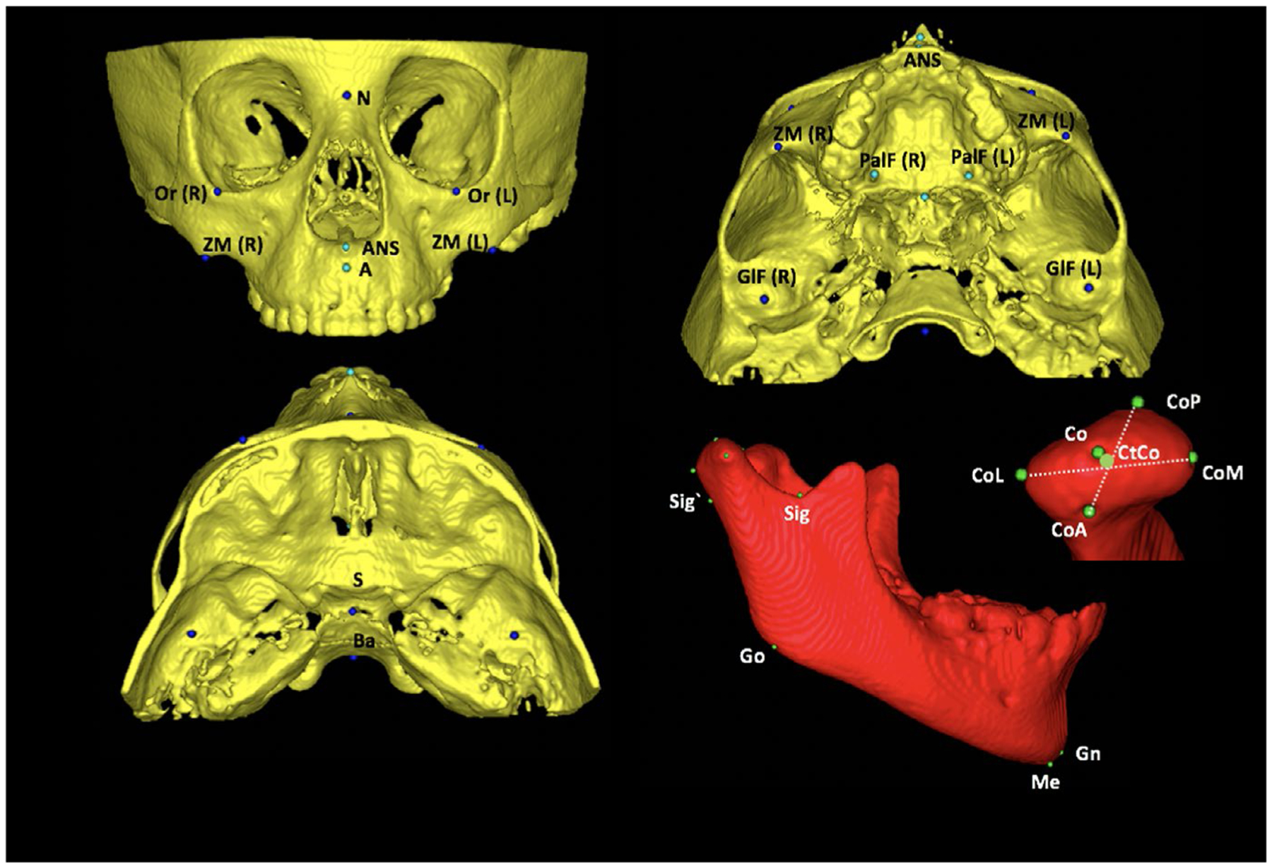
Anatomical landmarks used in measurement’s method. A, Landmarks of measurement’s method: orbitale (Or): most inferior point at the inferior contour of the orbit; zygomaticomaxillary (ZM): most inferior point at the zygomatic maxillary suture; anterior nasal spine (ANS): most anterior point at the anterior nasal spine; palatine foramen (PalF): the middle and inferior point at the palatine foramen; GlF (glenoid fossa): most superior point at the glenoid fossa; sella (S): midpoint at the sella turcica; basio (Ba): most inferior point at the anterior border of magnun foramen; 2-D: mandibular landmarks: condilium (Co): most superior point on the curvature of the condylar head; anterior pole (CoA): most anterior point of the condylar head; posterior pole (CoP): most posterior point of the condylar head; medial pole (CoM): most medial point of the condylar head; lateral pole (CoL): most lateral point of the condylar head; centre of condyle (CtCo): centre point on the line connecting the centres of latero-medial and antero-posterior distances, sigmoid posterior (Sig`): most posterior point of the projection of sigmoid notch point using a line parallel to Frankfurt plane; gonion (Go): midpoint of the angle of the mandible determined by bisecting the angle formed by the mandibular plane and the adjacent line to mandibular ramus; gnathion (Gn): most anteroinferior and midline point on the contour of the bony chin symphysis, determined by bisecting the angle formed by the mandibular plane and a line through pogonion and nasion; and menton (Me): most inferior midline point on the mandibular symphysis
TABLE 1.
Craniofacial measurements
| Variable | Identification | Unit | Definition |
|---|---|---|---|
| Zygomatic measurements | |||
| Orbitale vertical position | Or-S SI | 2D linear (mm) | Supero-inferior distance between orbitale and sella |
| Orbitale antero-posterior position | Or-S AP | 2D linear (mm) | Antero-posterior distance between orbitale and sella |
| Orbitale lateral position | Or-S RL | 2D linear (mm) | Lateral distance between orbitale and sella |
| Zygomaticomaxillary vertical position | ZM-S SI | 2D linear (mm) | Supero-inferior distance between zygomaticomaxillary point and sella |
| Zygomaticomaxillary antero-posterior position | ZM-S AP | 2D linear (mm) | Antero-posterior distance between zygomaticomaxillary point and sella |
| Zygomaticomaxillary lateral position | ZM-S RL | 2D linear (mm) | Lateral distance between zygomaticomaxillary point and sella |
| Orbitale Roll—vertical inclination | Or(R)- Or (L).MSP | Degree (°) | Difference between the bilateral superior angle of the Orbitale bilateral points line and the MSP |
| Orbitale Yaw—horizontal inclination | Or(R)-Or(L).MSP | Degree (°) | Difference between the bilateral anterior angle of the Orbitale bilateral points line and the MSP |
| Zygomaticomaxillary Roll—vertical inclination | ZM(R)-ZM(L).MSP | Degree (°) | Difference between the right and left superior angle of the zygomaticomaxillary bilateral points line and the MSP |
| Zygomaticomaxillary Yaw—horizontal inclination | ZM(R)-ZM(L).MSP | Degree (°) | Difference between the right and left anterior angle of the zygomaticomaxillary bilateral points line and the MSP |
| Maxillary measurements | |||
| Maxillary deviation | ANS-MSP | 2D linear (mm) | Latero-medial distance between the ANS point to MSP line |
| Palatine foramen position | PalF-S SI | 2D linear (mm) | Supero-inferior distance between palatine foramen and sella |
| Palaine foramen antero-posterior position | PalF-S AP | 2D linear (mm) | Antero-posterior distance between palatine foramen and sella |
| Palatine foramen lateral position | PalF-S RL | 2D linear (mm) | Lateral distance between palatine foramen and sella |
| Palatine foramen Roll—vertical inclination | PalF(R)-PalF(L).MSP | Degree (°) | Difference between the right and left superior angle of the palatine foramen bilateral points line and the MSP |
| Palatine foramen Yaw—horizontal inclination | PalF(R)-PalF(L).MSP | Degree (°) | Difference between the right and left anterior angle of the palatine foramen bilateral points line and the MSP |
| Glenoid fossa measurements | |||
| Glenoid fossa vertical position | GlF-S SI | 2D linear (mm) | Supero-inferior distance between glenoid fossae and sella |
| Glenoid fossa antero-posterior position | GlF-S AP | 2D linear (mm) | Antero-posterior distance between glenoid fossae and sella |
| Glenoid fossa lateral position | GlF-S RL | 2D linear (mm) | Lateral distance between glenoid fossae and sella |
| Glenoid fossa Roll—vertical inclination | GlF(R)-GlF (L).MSP | Degree (°) | Difference between the right and left superior angle of the glenoid fossae bilateral points line and the MSP |
| Glenoid fossa Yaw—horizontal inclination | GlF(R)-GlF (L).MSP | Degree (°) | Difference between the right and left anterior angle of the glenoid fossae bilateral points line and the MSP |
| Condylar linear measurements | |||
| Condylar process height | Co-Sig` | 2D linear (mm) | Supero-inferior distance between condilium and the correspondent point of sigmoid notch in the posterior region of condylar neck |
| Condylar Height (Co-CtCo) | Co-CtCo | 2D linear (mm) | Superior-inferior distance between condilium and the centre of the condyle |
| Lat-Med Width (lat-med poles) | CoL-CoM | 3D linear (mm) | Latero-medial distance between the lateral and medial poles of condyle |
| Ant-post width (ant-post poles) | CoA-CoP | 3D linear (mm) | Antero-posterior distance between the anterior e posterior poles of condyle |
| Mandibular linear measurements | |||
| Chin deviation | Me-MSP | 2D linear (mm) | Latero-medial distance between the Me point to MSP line |
| Ramus height | Sig`-Go | 2D linear (mm) | Supero-inferior distance between the correspondent point of sigmoid notch in the condylar neck and gonion |
| Total ramus height | Co-Go | 2D linear (mm) | Supero-inferior distance between the condilium and gonion |
| Mandibular length | Co-Gn | 3D linear (mm) | Distance between condilium and gnathion |
| Mandibular body | Go-Gn | 3D linear (mm) | Distance between gonion and gnathion |
| Ramus inclination | |||
| Antero-posterior | CtCoGo.GoGn | Degree (°) | Antero-posterior inclination of mandibular ramus |
| Lateral | CtCoGo. MSP | Degree (°) | Latero-medial inclination of the mandibular ramus to MSP line. |
| Lateral hemimandibular angle | |||
| Lateral | CtCoMe.MSP | Degree (°) | Latero-medial inclination of the mandibular body to MSP line. |
| Mandibular position | |||
| Yaw (mandibular horizontal rotation) | CoMe(or).CoMe(mir) | Degree (°) | Angle between the CoMe line at the right original side and CoMe at the ‘right’ mirrored side. |
FIGURE 2.
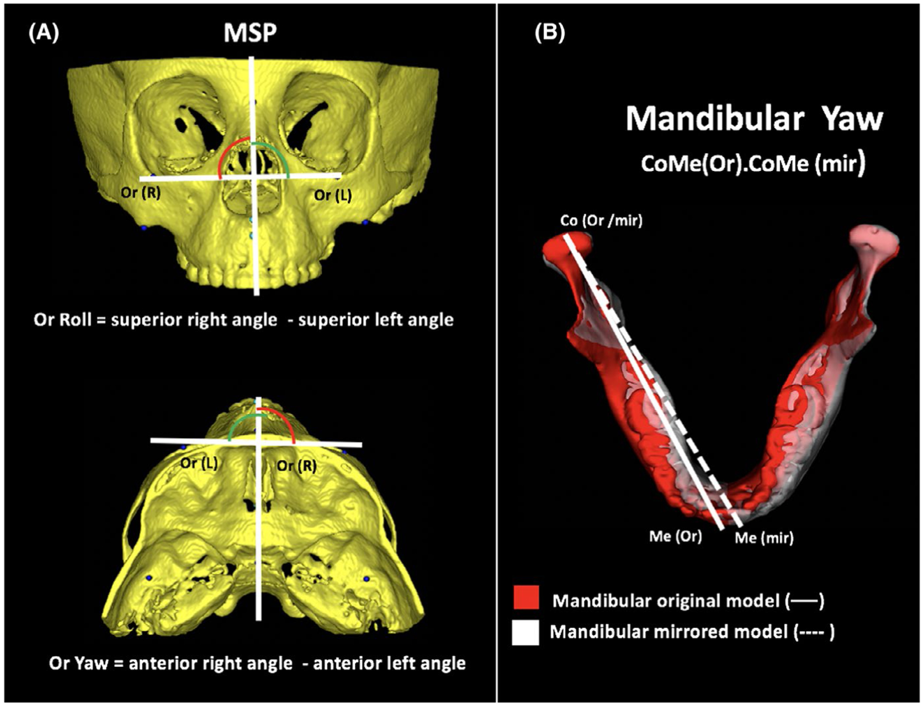
Craniofacial roll and yaw assessment in the study’s method. A, Illustration of roll and yaw measurement of Orbitale. B, Illustration of yaw in mandible, using superimposition of original and mirrored models
2.5 |. Statistical analysis
The statistical analysis was performed with the SPSS Statistical Software Package (version 23.0; IBM). All variables distributions were tested using Kolmogorov-Smirnov test and showed normal distribution. The random error was determined using Dahlberg’s formula, and the systematic error was detected by ICC test with a confidence level of 95%, which verified the reproducibility after repeating all pre-labelled landmarks and measurements of 20 patients with 15-day interval, randomly selected from total sample. All side comparisons in both groups were calculated using MANOVA analysis considering the crossbite malocclusion in each side added by power analysis. Intergroup comparisons before and after RME treatment (using the intragroup side’s differences) were performed with t test for independent samples. The level of significance was set at 0.05 for all tests. The effect size of each significant difference was calculated to determine clinical effect significance. Values under 2.0 were considered weak, moderate when between 0.50 and 0.80, and strong when above 0.80.31
3 |. RESULTS
3.1 |. Reliability
All 3D measurements showed a high intra-examiner reliability. Operator error measurements varied between 0.03 and 0.67 mm. The lowest ICC value was for lateral position of palatine foramen (PalF-RL, 0.883) and the highest was for ramus height (Sig`-Go, 0.999).
3.2 |. Sample characteristics
Four patients in the crossbite group had loss of segment due to change of address (n = 1), treatment interruption (n = 2) and loss of contact (n = 1). All 26 patients of non-crossbite group completed the study. The sample baseline characteristics (sex, age, time between T1 and T2 scans, ANB, chin deviation, maxillary deviation) are described in Table 2. In both groups, female sample was more prevalent. Chin deviation characterized the sample with mandibular asymmetry, and that was slightly increased in crossbite group. Non-crossbite group showed greater Class II skeletal relationship, but not statistically significant.
TABLE 2.
Statistical comparison for sex, age, T1-T2 interval, ANB, chin and maxillary deviation between crossbite and non-crossbite groups and craniofacial variables between both craniofacial sides at baseline (T1)
| Crossbite group (n = 25) | non-crossbite group (n = 26) | 95% CI of mean diff | |||||
|---|---|---|---|---|---|---|---|
| Mean | SD | Mean | SD | Mean Diff | P value | ||
| Sex (Female/Male)a | 17/8 | 14/12 | .393 | ||||
| Age (y)b | 6.68 | 1.47 | 7.41 | 1.31 | −0.63 | −1.45;0.18 | .128 |
| T1-T2 (y)b | 1.30 | 0.23 | 1.42 | 0.24 | −0.10 | −0.25; 038 | .145 |
| Maxillary/Mandibular | |||||||
| ANB (°)b | 3.86 | 2.24 | 4.93 | 2.44 | −1.07 | −2.39;0.25 | .110 |
| Chin deviation | |||||||
| Me-MSP (mm)b | 1.61 | 1.12 | 1.11 | 0.84 | 0.49 | −0.06;1.05 | .080 |
| Maxillary deviation | |||||||
| ANS-MSP (mm)b | 0.77 | 0.67 | 1.00 | 0.81 | −0.23 | −0.65;0.19 | .277 |
Chi-square test.
t test for independent samples (P < .05).
Effect size low—0.2.
Effect size medium—0.50.
Effect size high—0.80.
3.3 |. Side comparisons
All side comparisons in both groups of craniofacial regions at T1 are shown in Table 3. The crossbite group showed in T1 no significant difference in the side sizes. The non-crossbite group revealed the right size larger in orbitale RL (2.95, 3.25 and 3.37 mm,) and palatine foramen RL (1.16, 1.36, 0.96 mm) in comparison with crossbite side, non-crossbite side and left side, respectively. The non-crossbite group also showed larger condylar height at right side compared to crossbite (0.49 mm) and non-crossbite sides (0.46 mm). The palatine foramen SI position is symmetric in both groups but positioned more inferiorly in non-crossbite group, expressing a mean difference of 1.9 mm. The results of the observed power analysis showed that all statistically significant variables had power greater than 77%.
TABLE 3.
Craniofacial variables between both craniofacial sides at baseline (T1)
| Crossbite group (n = 25) | non-crossbite group (n = 26) | |||||
|---|---|---|---|---|---|---|
| Crossbite side | Non-crossbite side | Right side | Left side | P value | Observed power | |
| Zygomatic variables | ||||||
| Orbitale SI (Or-S) | 16.77 (2.06) | 16.69 (1.90) | 16.34 (2.17) | 16.46 (2.24) | .876 | 0.092 |
| Orbitale AP (Or-S) | 47.23 (3.33) | 47.39 (3.21) | 47.91 (3.07) | 48.50 (3.65) | .519 | 0.208 |
| Orbitale RL (Or-S) | 32.36 (2.71) A | 32.34 (3.03) A | 35.79 (2.12) B | 32.83 (1.94) A | <.001*** | 0.999 |
| Zygomatic maxillary SI (ZM-S) | 31.11 (3.06) | 31.02 (2.37) | 32.41 (2.80) | 32.22 (2.91) | .166 | 0.439 |
| Zygomatic maxillary AP (ZM-S) | 37.58 (3.33) | 37.37 (3.43) | 38.71 (3.11) | 38.92 (3.22) | .227 | 0.378 |
| Zygomatic maxillary RL (ZM-S) | 37.67 (2.73) | 38.32 (3.06) | 39.37 (1.46) | 38.03 (1.59) | .059 | 0.617 |
| Maxillary variables | ||||||
| Palatine foramen SI (PalF-S) | 35.26 (2.68) A | 35.66 (2.51) A | 37.11 (2.59) B | 37.16 (2.67) B | .017* | 0.774 |
| Palatine foramen AP (PalF-S) | 23.20 (2,92) | 23.36 (3.28) | 24.67 (2.66) | 24.69 (2.61) | .114 | 0.509 |
| Palatine foramen RL (PalF-S) | 12.77 (0.93) A | 13.14 (1.47) A | 14.07 (1.48) B | 12.91 (1.17) A | .002** | 0.925 |
| Glenoid Fossa | ||||||
| Glenoid Fossa SI (GlF-S) | 15.34 (2.06) | 15.00 (1.71) | 15.67 (2.50) | 15.53 (2.45) | .726 | 0.135 |
| Glenoid Fossa AP (GlF-S) | 8.15 (2.62) | 8.12 (2.96) | 8.55 (2.39) | 8.52 (2.43) | .895 | 0.087 |
| Glenoid Fossa RL (GlF-S) | 43.54 (2.10) | 43.29 (2.39) | 43.53 (2.52) | 43.20 (2.33) | .059 | 0.617 |
| Mandible variables | ||||||
| Condylar measurements (mm) | ||||||
| Condylar process height (Co-Sig`) | 12.08 (2.39) | 12.17 (1.72) | 13.37 (2.43) | 13.37 (2.38) | .056 | 0.624 |
| Condylar Height (Co-CtCo) | 4.29 (0.71) A | 4.33 (0.69) A | 5.03 (0.80) B | 4.52 (1.24) AB | .014* | 0.793 |
| Lat-Med Width (lat-med poles) | 16.46 (1.93) | 16.25 (2.08) | 16.63 (1.73) | 16.24 (2.01) | .868 | 0.094 |
| Ant-post width (ant-post poles) | 10.02 (1.63) | 10.09 (1.72) | 10.91 (1.08) | 10.61 (1.10) | .085 | 0.558 |
| Mandible linear measurements (mm) | ||||||
| Ramus height (Sig’-Go) | 30.32 (3.51) | 30.16 (2.99) | 30.85 (3.72) | 30.14 (3.62) | .872 | 0.093 |
| Total ramus height (Co-Go) | 42.38 (3.38) | 42.24 (3.73) | 44.22 (3.80) | 43.41 (3.70) | .183 | 0.421 |
| Mandibular length (Co-Gn) | 100.23 (5.71) | 100.85 (6.15) | 103.22 (4.89) | 103.05 (4.74) | .116 | 0.505 |
| Mandibular body (Go-Gn) | 71.33 (4.10) | 72.02 (4.55) | 73.55 (3.36) | 73.87 (3.77) | .074 | 0.581 |
| Ramus inclination (°) | ||||||
| Antero-posterior (CtCo.GoGn) | 121.53 (4.55) | 121.96 (5.79) | 121.86 (4.58) | 121.71 (4.52) | .990 | 0.056 |
| Lateral (CtCoGo.MSP) | 7.67 (3.81) | 8.18 (3.64) | 6.53 (3.08) | 6.21 (2.92) | .131 | 0.484 |
| Lateral hemimandibular angle | ||||||
| CtCoMe.MSP | 36.12 (2.71) | 38.89 (2.21) | 35.62 (3.73) | 36.57 (3.57) | .405 | 0.260 |
Note: MANOVA analysis was performed between sides comparisons including the malocclusion in each side (P < .05).
Different letters represent statistical significance among groups and same letters no statistical significance.
Bold values represent statistically siginificant values.
Weak effect size: <0.20.
Moderate effect size: 0.50–0.80.
Strong effect size ≥ 0.80.
3.4 |. RME effects comparison
The intergroup comparison of mandibular measurements before RME is shown in Table 4 and resulted differences statistically significant between crossbite and non-crossbite group, meaning in greater mandibular horizontal rotation and lateral hemimandibular asymmetry in children with unilateral posterior crossbite.
TABLE 4.
Comparison of craniofacial asymmetries between crossbite and non-crossbite groups in T1 and T2 expressed by mean and 95% CI
| T1 | T2 | |||||||
|---|---|---|---|---|---|---|---|---|
| Crossbite group (n = 25) | non-crossbite group (n = 26) | 95% IC | P- value | Crossbite group (n = 21) | non-crossbite group (n = 26) | 95% IC | P- value | |
| Zygomatic asymmetry | ||||||||
| Orbitale SI (Or-S) | 0.08 (0.80) | −0.11 (0.99) | −0.31;0.70 | .449 | 0.13 (0.94) | −0.13 (0.87) | −0.26;0.80 | .308 |
| Orbitale AP (Or-S) | −0.15 (1.73) | −0.58 (1.60) | −0.51;1.36 | .365 | −0.45 (1.91) | −0.69 (1.34) | −0.71;1.19 | .615 |
| Orbitale RL (Or-S) | 0.02 (3.03) | 2.95 (2.36) | −4.46; −1.40 | <.001*** | 0.00 (2.93) | 2.19 (1.81) | −3.68; −0.69 | .005** |
| Zygomatic maxillary SI (ZM-S) | 0.08 (1.25) | 0.19 (0.80) | −0.69;0.48 | .724 | 0.04 (1.25) | 0.22 (1.02) | −0.85;0.48 | .586 |
| Zygomatic maxillary AP (ZM-S) | 0.21 (1.64) | −0.21 (1.42) | −0.43;1.29 | .325 | 0.44 (1.61) | 0.52 (2.71) | −1.43;1.27 | .903 |
| Zygomatic maxillary RL (ZM-S) | −0.64 (1.52) | 1.33 (1.57) | −2.85;−1.10 | <.001*** | −0.80 (1.59) | 1.09 (2.10) | −3.02; −0.78 | .001** |
| Orbitale Roll (Or(R)-Or(L).MSP) | 0.16 (1.34) | 0.33 (2.35) | −1.53;0.69 | .456 | 0.15 (2.60) | −0.37 (2.50) | −0.70;1.77 | .392 |
| Orbitale Yaw (Or(R)-Or(L).MSP) | −0.34 (2.38) | 1.85 (2.97) | −3.68; −0.64 | .006*** | 0.56 (4.11) | 0.65 (2.65) | −2.08;1.91 | .930 |
| Zygomatic maxillary Roll (ZM(R)-ZM(L).MSP) | −0.13 (1.76) | 0.79 (1.82) | −1.97;0.05 | .063 | 0.02 (2.70) | 0.22 (1.62) | −1.48;0.08 | .759 |
| Zygomatic maxillary Yaw (ZM(R)-ZM(L).MSP) | −0.83 (1.70) | 0.94 (2.91) | −3.10; −0.42 | .010** | −0.40 (4.61) | −0.29 (2.91) | −2.33;2.11 | .920 |
| Maxillary asymmetry | ||||||||
| ANS deviation | 0.22 (1.01) | 0.75 (1.04) | −1.11;0.04 | .069 | 0.24 (1.30) | 0.68 (1.04) | −1.12;0.24 | .206 |
| Palatine foramen SI (PalF-S) | −0.39 (1.09) | 0.50 (1.10) | −0.96;0.27 | .268 | −0.15 (1.17) | 0.25 (1.29) | −1.14;0.32 | .266 |
| Palatine foramen AP (PalF-S) | −0.16 (0.72) | −0.19 (1.53) | −0.76 ;0.82 | .940 | 0.02 (0.73) | 0.33 (1.64) | −0.76 ;0.82 | .424 |
| Palatine foramen RL (PalF-S) | −0.37 (1.96) | 1.16 (1.69) | −2.56; −0.50 | .004** | −0.26 (2.06) | 0.93 (1.68) | −2.32; −0.06 | .034* |
| Palatine foramen Roll (PalF(R)-PalF(L).MSP) | −1.58 (4.69) | 1.02 (5.02) | −5.34;0.13 | .062 | −0.53 (6.00) | 1.55 (5.15) | −5.36;1.90 | .206 |
| Palatine foramen Yaw (PalF(R)-PalF(L).MSP) | 0.72 (3.14) | 0.64 (3.29) | −1.73;1.88 | .934 | −0.06 (4.23) | −0.61 (3.50) | −1.72;2.82 | .628 |
| Glenoid Fossa asymmetry | ||||||||
| Glenoid Fossa SI (GlF-S) | 0.34 (1.49) | 0.13 (0.94) | −0.49;0.90 | .562 | 0.42 (1.23) | 0.26 (1.07) | −0.51;0.83 | .635 |
| Glenoid Fossa AP (GlF-S) | 0.37 (2.40) | 0.32 (2.19) | −1.28;1.29 | .994 | 0.20 (2.33) | −0.05 (2.01) | −1.01;1.53 | .684 |
| Glenoid Fossa RL (GlF-S) | 0.25 (2.20) | 0.33 (2.18) | −1.31;1.15 | .898 | −0.25 (2.43) | 0.69 (1.57) | −2.13;0.23 | .113 |
| Glenoid Fossae Roll (GlF(R)-GlF(L).MSP) | −0.20 (1.77) | 0.50 (1.50) | −1.47;0.47 | .315 | 0.55 (2.30) | 0.13 (1.48) | −0.69;1.53 | .454 |
| Superior Zygomatic Yaw (GlF(R)-GlF(L).MSP) | −0.63 (2.28) | 0.31 (2.94) | −2.31;0.65 | .265 | 0.21 (3.94) | −0.28 (2.76) | −1.47;2.47 | .614 |
| Mandible asymmetry | ||||||||
| Chin deviation | 0.11 (1.98) | 0.20 (1.40) | −1.05;0.87 | .845 | 0.00 (1.70) | 0.09 (1.25) | −0.95;0.78 | .838 |
| Condylar measurements (mm) | ||||||||
| Condylar process height (Co-Sig`) | −0.08 (2.13) | 0.00 (1.38) | −1.10;0.91 | .851 | −0.07 (1.14) | 0.18 (1.90) | −1.21;0.68 | .581 |
| Condylar Height (Co-CtCo) | −0.03 (0.64) | 0.51 (1.05) | −1.04; −0.05 | .030* | −0.05 (0.70) | 0.00 (0.64) | −0.45;0.33 | .759 |
| Lat-Med Width (lat-med poles) | 0.21 (0.89) | 0.39 (1.17) | −0.76;0.40 | .544 | 0.11 (0.90) | 0.45 (0.97) | −0.90;0.21 | .225 |
| Ant-post width (ant-post poles) | −0.07 (1.13) | 0.29 (1.29) | −1.06;0.31 | .280 | 0.07 (1.16) | −0.12 (1.21) | −0.50;0.91 | .556 |
| Mandible linear measurements (mm) | ||||||||
| Ramus height (Sig’-Go) | 0.15 (2.60) | 0.70 (1.86) | −1.82;0.71 | .387 | −0.19 (2.10) | 0.63 (1.47) | −1.88;0.22 | .120 |
| Total ramus height (Co-Go) | 0.13 (1.91) | 0.80 (1.57) | −1.65;0.31 | .179 | 1.16 (6.48) | 0.22 (1.63) | −1.72;3.59 | .482 |
| Mandibular length (Co-Gn) | −0.61 (1.14) | 0.16 (1.46) | −1.52; −0.04 | .039* | −0.45 (1.34) | −0.03 (1.31) | −1.19;0.37 | .293 |
| Mandibular body (Go-Gn) | −0.69 (1.87) | −0.31 (1.54) | −1.33;0.59 | .439 | −0.46 (1.68) | −0.14 (0.95) | −1.15;0.52 | .423 |
| Ramus inclination (°) | ||||||||
| Antero-posterior (CtCo.GoGn) | −0.43 (3,15) | 0.14 (3.53) | −2.46;1.30 | .541 | −0.15 (2.69) | −0.29 (2.67) | −1.47;1.72 | .865 |
| Lateral (CtCoGo.MSP) | −0.50 (3.49) | 0.31 (2.68) | −2.56;0.93 | .351 | 0.00 (3.41) | −0.13 (2.11) | −1.49;1.78 | .857 |
| Lateral hemimandibular angle | ||||||||
| CtCoMe.MSP | −2.74 (3.50) | −0.32 (3.81) | −6.17; −1.02 | >.001*** | −0.95 (4.37) | −0.04 (2.79) | −3.01;1.21 | .395 |
| Mandibular horizontal position | ||||||||
| Yaw (CoMe(or).CoMe(mir) | 1.84 (1.91) | 0.61 (2.29) | 0.34;2.41 | .040* | 0.54 (2.27) | 0.02 (2.65) | −0.95;1.98 | .485 |
Note: Independent t test analysis was performed between malocclusion comparisons (P < .05).
Negative values considered shorter distances at crossbite/right side. Positive values considered larger distances at crossbite/right side.
Bold values represent statistically siginificant values.
Weak effect size: <0.20.
Moderate effect size: 0.50–0.80.
Strong effect size ≥ 0.80.
The differences between right and left sides in non-crossbite group at T1 showed statistically significant differences in lateral positions of the orbital (Or-RL), zygomaticomaxillary suture (ZM-RL) and palatine foramen (PalF-RL). In means, the right side was greater 2.95 mm ± 2.36, 1.33 mm ± 1.57, and 1.16 mm ± 1.69, respectively, in those dimensions. The Or-RL, ZM-RL and PalF-RL differences and orbitale and zygomatic maxillary yaw in non-crossbite group at T1 were also statistically significant in intergroup comparison. The horizontal rotation (yaw) for orbitale and zygomatic maxillary regions showed 1.85°± 2.97 and 0.94°± 2.91 in means, respectively, but no significance at maxillary level (palatine foramen yaw). Regarding antero-posterior position, the majority of variables showed symmetric position before RME, except for the Or-AP, which showed a slight posterior position on the right side (−0.58 mm ± 1.60). The T1 mandibular measurements at right side showed greater condylar (0.51 mm ± 1.05) and total ramus height (0.80 mm ± 1.57). These mandibular asymmetries found were also statistically significant for intergroup comparison. Both groups did not show asymmetries in glenoid fossa measurements.
The craniofacial asymmetries in T2 showed the differential RME effects in the midface and mandibular regions, as seen in Figure 3 and in Table 3. Despite the improvement of yaw rotation of the midface in non-crossbite group, there was still a statistically significant difference between groups in orbitale-RL (2.19 mm ± 1.81) and zygomatic maxillary-RL regions (1.09 mm ± 2.10) after RME. The maxillary asymmetry at palatine foramen showed a slight improvement in the difference between both sides (from 1.16 mm ± 1.69 to 0.93mm ± 1.68) in non-crossbite group. The palatine foramen asymmetry also showed a weak effect size of this measurement difference between groups after RME.
FIGURE 3.
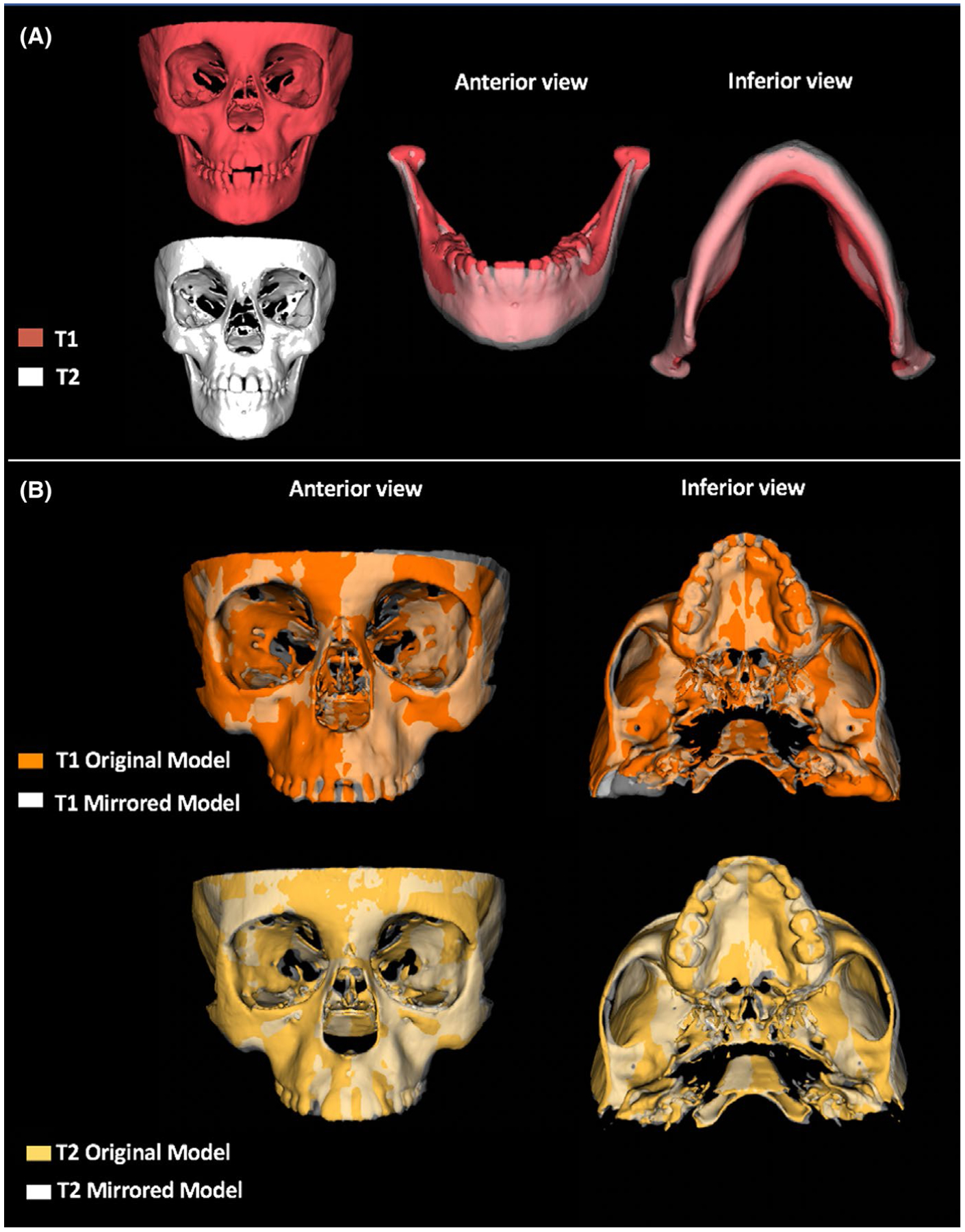
Summary illustration of the RME treatment results in asymmetry. A, 3D models in T1 and T2 of patient with functional unilateral posterior crossbite showing the shift change towards the left side after RME. B, 3D superimposition of patient with transverse maxillary deficiency and no posterior crossbite in T1 and T2 showing craniofacial regions more prominent at right side, as seen in zygomatic arch and maxilla
4 |. DISCUSSION
This study rejects the previous hypotheses that patients with UPC have asymmetric maxilla and/or cranial base and brought new knowledge about the craniofacial asymmetry in patients with transversal maxillary deficiency and non-crossbite. These study findings on the RME effects on asymmetry of different regions of craniofacial morphology offer new information to the orthodontic treatment in patients with transversal maxillary deficiency. Functional UPC at baseline influenced the mandibular position and contributed to mandibular asymmetry. Interestingly, children with narrow maxilla, but no posterior crossbite, showed more asymmetries in the zygomatic arch and maxilla, probably as intrinsic compensations to a narrow maxilla. In both groups, RME improved asymmetries, especially in mandibular rotation, but there was less influence on zygomatic and maxillary asymmetries.
The proposed imaging method used in this study detected the craniofacial asymmetries in the cranial base, maxilla and mandible in a previously oriented scan. The choice of a horizontal reference plane (‘3D Frankfurt horizontal plane’), instead of conventional Frankfurt plane, was due to have a plane that represented both sides three-dimensionally. Frankfurt plane priories the right side, and its use may overestimate or underestimate the measurements for one side. The voxel size and resolution parameters of the images, as well the analysis steps, were able to generate 3D models with sufficient quality to identify the landmarks proposed in this study with precision, as resulted in the error method calculation. Previous studies used to analyse mandibular asymmetries with 3D mirrored models also reported high accuracy, with mean values of errors under 0.5 mm or 0.5°.23,24 Regarding the asymmetries in the middle face (zygomatic and orbital regions), a previous study in adult patients with posterior crossbite used 2D frontal cephalograms and found small asymmetries, less than 3mm between both sides.25 2D images have not been considered the method of choice to detect asymmetries due to the superimposition of the bones, irregular structures of the middle face and differences in head position during X-ray exposition. In all cases, errors are generated to landmark identification and measurements.32
Previous assessments of asymmetry in children with functional UPC had been focused in the mandible.5–8,12–16 There is some evidence that this malocclusion influences condyle position,6,16 with condylar head positioned asymmetrically in the glenoid fossa when compared to normal occlusion groups.16 The vertical position of the condyle seems to be the main difference between crossbite and non-crossbite sides.6,16 Pinto et al6 showed shorter distances on the superior space of temporomandibular joint, in order of 0.8 mm, in mean. In contrast to positional features, morphological asymmetries in mandible are considered a controversial outcome, since 3D studies showed similar morphological asymmetries in patients with normal occlusion6,16 in contrast to another 2D study that found asymmetries in condylar height.14 Our study showed few differences in craniofacial morphology between both sides, and, when present, the effect size was low, as seen in mandibular length (Table 4). The mean differences of that dimension were −0.61 mm ± 1.14, respectively, and should not be considered clinically critical. It is important to emphasize that this study analysed only skeletal features. The combination of soft tissue position and skeletal position can be interesting to identify the role of each tissue in facial asymmetry when unilateral posterior crossbite is present.
Patients with non-posterior crossbite can present asymmetries in various craniofacial regions, especially zygomatic and maxillary regions, and few in the mandible. Another interesting result was the progressive magnitude of the asymmetries dimensions from the lower third to upper located bones. While in mandible, the morphological differences were limited by condylar height (0.51 ± 1.05), the maxillary region showed larger asymmetries (1.16 ± 1.69), with stronger effect size than in mandible. These results were also seen by the outcomes in zygomatic area, as in lateral position of the zygomatic maxillary suture (1.33 mm ± 1.57) and orbitale (2.95 mm ± 2.36), indicating proportions twice to 6 times of asymmetries found in the lower third of the face. It is also important to highlight that even in the more asymmetric maxillary, zygomatic and orbital measurements, the values were under 3.0mm. Previous study considered facial asymmetries more than 2.0 mm a cut-off to determine the presence of a relative asymmetry. Side differences greater than 4 mm are considered severe asymmetry.27
UPC in children did not influence the morphological symmetry in the glenoid fossa, despite the mandibular shift. According to previous studies, the articular space is an asymmetric condition, since the non-crossbite side shows larger superior space than the crossbite side.6,7 The largest mean difference between both sides was found in crossbite group (0.34 mm) but was not statistically significant. Leonardi et al16 have found statistically significant changes in superior articular spaces after RME, in order of 0.30 mm in means, and also found symmetric glenoid fossa. The RME outcomes in our study showed changes in superior limit of glenoid fossa restricted to 0.10 mm and were not considered statistically significant. The result supports that the asymmetry in children with functional UPC is more related to an asymmetric functional position rather than a true morphological difference between both sides.
RME has been considered an effective orthopaedic approach in promoting oral and generalized health, including improvement in oral hygiene, masticatory cycle and breathing function.33 Many studies had shown that children with functional UPC had unquestionable improvement of asymmetric mandibular position after RME.6,7,12,16 The results of our study also reinforces the asymmetries can promote few changes in the middle third of face. Previous publication of the RME effects on craniofacial structures had demonstrated the changes in circumaxillary sutures, such as zygomaticomaxillary, frontomaxillary sutures and also spheno-occipital synchondrosis in young patients.21,22 In the present study, the maxillary expansion on circumaxillary sutures was not been able to completely correct the asymmetry. The improvement of the initial asymmetric condition could be better understood if this study included a control group of untreated subjects. This approach would clarify the role of craniofacial growth during the observation period, RME effects or combination of both. Future studies can open a new window of timing for orthodontics clinical practice in order to take advantage of earlier stages of sutural maturation for the asymmetry correction. Despite the results showed few changes in morphological asymmetries in middle third of the face, the maxillary expansion evidenced a positive response on the correction of asymmetric position of the mandible in crossbite group.
Our results bring new perspectives on craniofacial asymmetries in different regions when patients with maxillary transversal deficiency do or do not present unilateral posterior crossbite. The baseline features shown in Table 2 for both groups showed a homogeneous sample, except for the posterior crossbite occurrence. Although no specific previous analysis had focused on craniofacial asymmetries in children with posterior crossbite, studies using dry skulls of foetus and children observed an existence of palatal and zygomatic asymmetry before the occlusion be stablished.34,35 It is important to emphasize that the present study analysed only skeletal features. Future studies assessing the combination of soft tissue position and skeletal position can be interesting to identify the role of each tissue in facial asymmetry when unilateral posterior cross-bite is present.
In face of these results, two questions arise: Is the early mandibular shift a mechanism to decrease asymmetries in the maxilla and zygoma? Does the dentoalveolar inclination of posterior teeth influence asymmetry or does it compensate skeletal asymmetry conditions? The difference in dental inclination between both sides in subjects with transversal maxillary deficiency has not been measured three-dimensionally in young children with or without unilateral posterior crossbite. Further longitudinal studies can answer those questions.
The use of CBCT has been discussed in different guidelines to orient all clinicians how to prescribe CBCT examinations.36,37 It is important to highlight that CBCT scans in children are not for RME purpose. The available CBCT scans in this study were previously acquired for diagnosis and treatment evaluation of sleep disorders and airway obstruction. In this previously collected sample, the image acquisition parameters had been adjusted to reduce ionizing radiation effects, such as adjusted FOV, lower exposure time and larger voxel size, following the ALADAIP principles.38
The prescription of CBCT examinations also impacted in one of the study limitations. Until now, there is no indication to use the tomographic images in a population with normal occlusion, especially in children.38 For this reason, a control group with normal occlusion was avoided in this study. Another limitation was patients were followed for just one year and a relative small sample size. Patients with older age and larger asymmetries conditions must be investigated to identify if the craniofacial asymmetries in patients with narrower maxilla are stable or progressive conditions.
5 |. CONCLUSIONS
Children with transverse maxillary deficiency have different craniofacial asymmetries, depending on the presence or not of UPC;
Morphological asymmetries in children with functional UPC are small and more restricted to the mandible;
Morphological asymmetries in children with transverse maxillary deficiency without posterior crossbite are more reflected in the zygomatic and maxillary regions;
The glenoid fossa is symmetric in children independently of the presence of UPC;
One year after RME treatment, the patients improved their craniofacial asymmetry, with significant changes in the mandible and correction of the mandibular rotation in patients with UPC.
ACKNOWLEDGEMENTS
This study was financed by NIH grant NIDCR R01 DE024450, and in part by the Coordenação de Aperfeiçoamento de Pessoal de Nível Superior—Brasil (CAPES)—Finance Code 001.
Funding information
Foundation for the National Institutes of Health, Grant/Award Number: NIDCR R01 DE024450; Coordenação de Aperfeiçoamento de Pessoal de Nível Superior, Grant/Award Number: 001
Footnotes
CONFLIC T OF INTEREST
All authors have nothing to disclose.
REFERENCES
- 1.Proffit WR, Fields HW Jr. Contemporary orthodontics, 5th edn St. Louis, MO: Mosby; 2012:768. [Google Scholar]
- 2.Melsen B, Stensgaard K, Pedersen J. Sucking habits and their influence on swallowing pattern and prevalence of malocclusion. Europ J Orthod. 1979;1:271–280. [DOI] [PubMed] [Google Scholar]
- 3.Adenoids L-A. Their effect on mode of breathing and nasal airflow and their relationship to characteristics of the facial skeleton and the dentition. Acta Otolaryngol Suppl. 1970;265:1–132. [PubMed] [Google Scholar]
- 4.Thilander B, Lennartsoon B. A study of children with unilateral crossbite, treated and untreated in deciduous dentition. J Orofac Orthop. 2002;63:371–383. [DOI] [PubMed] [Google Scholar]
- 5.Andrade AS, Gameiro GH, Derossi M, Gavião MB. Posterior cross-bite and functional changes.A systematic review. Angle Orthod. 2009;79:380–386. [DOI] [PubMed] [Google Scholar]
- 6.Pinto AS, Buschang PH, Throckmorton GS, Chen P. Morphological and positional asymmetries of young children with functional unilateral posterior crossbite. Am J Orthod Dentofacial Orthop. 2001;120:513–520. [DOI] [PubMed] [Google Scholar]
- 7.Kecik D, Kocadereli I, Saatci I. Evaluation of the treatment changes of functional posterior crossbite in the mixed dentition. Am J Orthod Dentofacial Orthop. 2007;131:202–215. [DOI] [PubMed] [Google Scholar]
- 8.Ishizaki K, Suzuki K, Mito T, Tanaka EM, Sato S. Morphologic, functional and occlusal characterization of mandibular lateral displacement malocclusion. Am J Orthod Dentofacial Orthop. 2010;137:454.e1–454.e9. [DOI] [PubMed] [Google Scholar]
- 9.Ferro F, Spinella P, Lama N. Transverse maxillary arch form and mandibular asymmetry in patients with posterior unilateral cross-bite. Am J Orthod Dentofacial Orthop. 2011;140:828–838. [DOI] [PubMed] [Google Scholar]
- 10.Sonessen L, Bakke M, Solow B. Bite force in pre-orthodontic children with unilateral crossbite. Eur J Orthod. 2001;23:741–749. [DOI] [PubMed] [Google Scholar]
- 11.Maspero C, Giannini L, Galbiati G, Kairyte L, Farronato G. Neuromuscular evaluation in young patients with unilateral posterior crossbite before and after rapid maxillary expansion. Stomatologija. 2015;17:84–88. [PubMed] [Google Scholar]
- 12.Ben-Bassat Y, Yaffe A, Brin I, Freeman J, Ehrlich Y. Functional and morphological-occlusal aspects in children treated for unilateral posterior cross-bite. Eur J Orthod. 1993;15:57–63. [DOI] [PubMed] [Google Scholar]
- 13.Lippold C, Hoppe G, Moiseenko T, Ehmer U, Danesh G. Analysis of condylar differences in functional unilateral crossbite during early treatment- a randomized clinical study. J Orofac Orthop. 2008;69:283–296. [DOI] [PubMed] [Google Scholar]
- 14.Kilic N, Kiki A, Oktay H. Condylar asymmetry in unilateral crossbite patients. Am J Orthod Dentofacial Orthop. 2008;133:382–387. [DOI] [PubMed] [Google Scholar]
- 15.Veli I, Uysal T, Ozer T, Ucar FI, Eruz M. Mandibular asymmetry in unilateral and bilateral crossbite patients using cone-beam computed tomography. Angle Orthod. 2011;81:966–974. [DOI] [PMC free article] [PubMed] [Google Scholar]
- 16.Leonardi R, Caltabiano M, Cavallini C, et al. Condyle fossa relationship associated with functional posterior crossbite, before and after rapid maxillary expansion. Angle Orthod. 2012;82:1040–1046. [DOI] [PMC free article] [PubMed] [Google Scholar]
- 17.Iodice G, Danzi G, Cimino R, Paduano S, Michelotti A. Association between posterior crossbite, skeletal, and muscle asymmetry: a systematic review. Eur J Orthod. 2016;38(6):638–651. [DOI] [PubMed] [Google Scholar]
- 18.Talapaneni AK, Nuvvula S. The association between posterior unilateral crossbite and craniomandibular asymmetry: a systematic review. J Orthod. 2012;39(4):279–291. [DOI] [PubMed] [Google Scholar]
- 19.Kanomi R, Deguchi T, Kakuno E, Takano-Yamamoto T, Roberts WE. CBCT of skeletal changes following rapid maxillary expansion to increase arch-length with a development-dependent bonded or banded appliance. Angle Orthod. 2013;83:851–857. [DOI] [PMC free article] [PubMed] [Google Scholar]
- 20.Primozic J, Ovsenik M, Richmond S, Kou CH, Zhurov A. Early crossbite correction: a three-dimensional evaluation. Eur J Orthod. 2009;31:352–356. [DOI] [PubMed] [Google Scholar]
- 21.Sicurezza E, Palazzo G, Leonardi R. Three-dimensional computerized tomographic orbital volume and aperture width evaluation: a study in patients treated with rapid maxillary expansion. Oral Surg Oral Med Oral Pathol Oral Radiol and Endod. 2011;111:503–507. [DOI] [PubMed] [Google Scholar]
- 22.Leonardi R, Sicurezza E, Cutrera A, Barbato E. Early post-treatment changes of circumaxillary sutures in young patients treated with rapid maxillary expansion. Angle Orthod. 2011;81:36–41. [DOI] [PMC free article] [PubMed] [Google Scholar]
- 23.Cevidanes LH, Alhadidi A, Paniagua B, et al. Three-dimensional quantification of mandibular asymmetry through cone-beam computerized tomography. Oral Surg Oral Med Oral Pathol Oral Radiol Endod. 2011;111:757–770. [DOI] [PMC free article] [PubMed] [Google Scholar]
- 24.AlHadidi A, Cevidanes LH, Mol A, Ludlow J, Styner M. Comparison of two methods for quantitative assessment of mandibular asymmetry using cone beam computed tomography image volumes. Dentomaxillofac Radiol. 2011;40:351–357. [DOI] [PMC free article] [PubMed] [Google Scholar]
- 25.Kusayama M, Motohashi N, Kuroda T. Relationship between transverse dental anomalies and skeletal asymmetry. Am J Orthod Dentofacial Orthop. 2003;123:329–337. [DOI] [PubMed] [Google Scholar]
- 26.Uysal T, Memili B, Usumez S, Sari Z. Dental and alveolar arch widths in normal occlusion, class II division 1 and class II division 2. Angle Orthod. 2005;75:941–947. [DOI] [PubMed] [Google Scholar]
- 27.Thiesen G, Gribel BF, Kim KB, Pereira KCR, Freitas MPM. Prevalence and associated factors of mandibular asymmetry in an adult population. J Craniofac Surg. 2017;28:e199–203. [DOI] [PubMed] [Google Scholar]
- 28.Schiffman E, Ohrbach R, Truelove E, et al. Diagnostic criteria for temporomandibular disorders (DC/TMD) for clinical and research applications: Recommendations of the international RDC/TMD consortium network* and orofacial pain special interest group. J Oral Facial Pain Headache. 2014;28:6–27. [DOI] [PMC free article] [PubMed] [Google Scholar]
- 29.Ruellas AC, Tonello C, Gomes LR, et al. Common 3-dimensional coordinate system for assessment of directional changes. Am J Orthod Dentofac Orthop. 2016;149:645–656. [DOI] [PMC free article] [PubMed] [Google Scholar]
- 30.Ruellas AC, Huanca Ghislanzoni LT, Gomes MR, et al. Comparison and reproducibility of 2 regions of reference for maxillary regional registration with cone-beam computed tomography. Am J Orthod Dentofac Orthod. 2016;149:533–542. [DOI] [PMC free article] [PubMed] [Google Scholar]
- 31.Cohen J. Statistical power analysis for the behavioral sciences, 2nd edn Hillsdale, NJ: Erlbaum; 1988:567. [Google Scholar]
- 32.Shokri A, Miresmaeili A, Farhadian N, Falah-Kooshki S, Amini P, Mollaie N. Effect of changing the head position on accuracy of transverse measurements of the maxillofacial region made on cone beam computed tomography and conventional posterior- anterior cephalograms. Dentomaxillofac Radiol. 2017;46:20160180. [DOI] [PMC free article] [PubMed] [Google Scholar]
- 33.McNamara JA Jr, Lione R, Franchi L, et al. The role of rapid maxillary expansion in the promotion of oral and general health. Prog Orthod. 2015;16:33. [DOI] [PMC free article] [PubMed] [Google Scholar]
- 34.Moreira RS, Sgrott EA, Stuker H, Alonso LG, Smith RL. Palatal asymmetry during development: an anatomical study. Clin Anat. 2008;21:398–404. [DOI] [PubMed] [Google Scholar]
- 35.Rossi M, Ribeiro E, Smith R. Craniofacial asymmetry in development: an anatomical study. Angle Orthod. 2003;74:381–385. [DOI] [PubMed] [Google Scholar]
- 36.American Academy of Oral and Maxillofacial Radiology. Clinical recommendations regarding use of cone beam computed tomography in orthodontics. Position statement by the American Academy of Oral and Maxillofacial Radiology. Oral Surg Oral Med Oral Pathol Oral Radiol Endod. 2013;116:238–257. [DOI] [PubMed] [Google Scholar]
- 37.European Commission. Radiation protection: Cone beam CT for dental and maxillofacial radiology (evidence-based guidelines). 2012;172:154 http://www.sedentexct.eu/files/radiation_protection_172.pdf Accessed September 24, 2019. [Google Scholar]
- 38.Oenning AC, Jacobs R, Pauwels R, Straits A, Hedesiu M, Salmon B. DIMITRA Research Group. Cone-beam CT in paediatric dentistry: DIMITRA peroject position statement. Pediatr Radiol. 2018;48:308–316. [DOI] [PubMed] [Google Scholar]