Abstract
Study Design:
Inlay cranioplasties following partial craniectomy in tumor or trauma cases and onlay cranioplasties for reconstructions of residual developmental skull anomalies are frequently performed using CAD-CAM techniques.
Objective:
In this case series, we present a novel cranial implant design, being a combination of 3D-printed titanium grade 23 and calcium phosphate paste (CeTi).
Methods:
The titanium patient-specific implant, manufactured using selective laser melting, has a latticed border with interconnected micropores. The cranioplasty is miniscrew fixed and its border zone subsequently partially filled with calcium phosphate paste to promote osteoinduction and osteoconduction. From April 2017 to April 2019, 8 patients have been treated with such a CeTi implant. The inlay cranioplasties were each time revision surgeries of complicated cases.
Results:
All implants were successful after a limited follow-up time (range 18-42 months). There were no dehiscences and no infections, and no complaints of thermal conduction.
Conclusions:
The proposed CeTi cranial implant combines the strength of titanium implants with the biological integration potential of ceramic implants and seems particularly resistant to infection, probably due to the biofunctionalized titanium surface and the antimicrobial activity of elevated intracellular free calcium levels.
Keywords: cranium, printing, three-dimensional, calcium phosphate, Ti-6Al-V4 alloy
Introduction
Our preferred material for patient-matched implants is 3D-printed titanium alloy. The rim of the implant shows a lattice structure that helps connect the alloplastic implant to the body-sided bonding element of bone.1 Osteoconduction and osteoinduction at the bone–scaffold interface can be further promoted by the following: screw and/or plate immobilization, choosing the appropriate interconnected pore size for the lattice structure,2 increasing wettability (plasma surface activation),3 micro-shot peening and acid etching (also known as “sandblasting, large grit, acid etching” [SLA]),4 and coating with nano-hydroxyapatite (HA). Unfortunately, the HA nanocoating dissolves during the hospital cleaning and autoclaving process,5 and the wettability also disappears.
We present inlay and onlay cranioplasties consisting of a 3D-printed titanium shell (patient-matched) with a lattice-structured rim that is intraoperatively filled with calcium phosphate paste. This allows for secondary biological bonding and antibacterial activity.6 Primary stability can be achieved by directed oblique screw fixation in the sidewall of the calvarial defect, a technique Rasse and Lindner developed,7 or by mono-cortical screw fixation in tabs on top of neighboring bone, as we currently prefer.
Case Material
Technical Aspects
Ceramic 3D-printed titanium cranioplasty (CeTi)
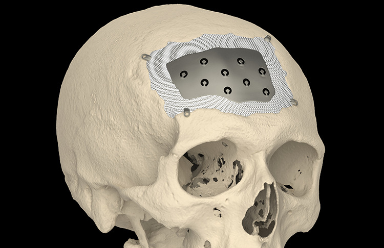
The CeTi implant (CADskills bvba, Ghent, Belgium) has a solid 1-mm thickness for defects <110 mm in diameter and a thickness of 1.5 mm for defects >110 mm in diameter. CeTi implants for defects >110 mm are designed using two pieces with a 3D-puzzle connection.8 The latticed border of the implant extends approximately 5 mm deep from the defect edge in the direction of the center of the implant (Figure 1). The dode thick 1.5-mm unit cell has an interconnected pore size of 1 mm, and the lattice structure is 2.5-mm thick.
Figure 1.
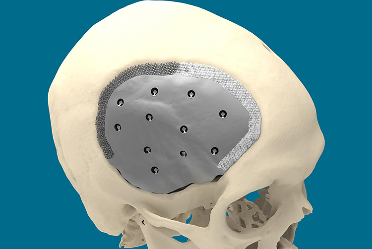
The border of the implant is scaffolded. Part of it is already filled with calcium phosphate paste (whitish). Space is left between the caudal edge of the plate and the bony defect edge, under the temporalis muscle as not to jeopardize the greater vessels in the area (deep temporal and middle meningeal arteries) during defect dissection.
The shell contains holes for to drainage, for dura suspension, and temporal muscle reattachment. CeTi is manufactured using selective laser melting (SLM). SLM is a powder-bed, fusion-based additive manufacturing process used to fabricate metallic parts.9 Ti-6Al-4V-alloy is the preferred material due to its high biocompatibility and strength-to-weight ratio.10
Oblique screw fixation
Pocket-hole joinery is a technique used in woodworking. It involves drilling a hole at an angle into two crafted objects and joining them with a self-tapping screw. It was first used for cranioplasty in 1990s after generation of prefabricated, computer-generated, individual carbon fiber-reinforced plastic medical grade implants (Medtronic-Sofamor Danek).7 A stereolithographic defect model was used to predetermine the position, direction, and length of the fixation screws (Figure 2).
Figure 2.
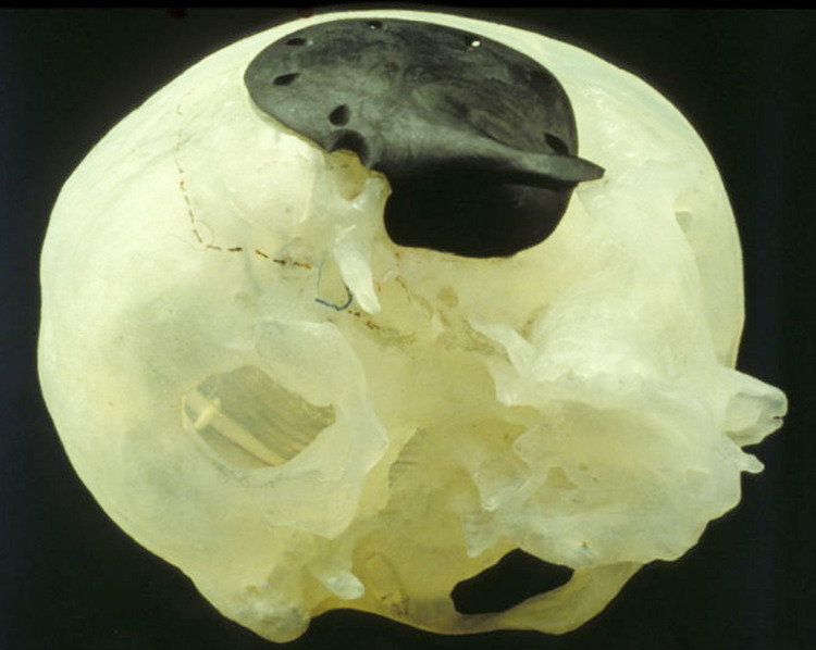
A CFRP implant (Medtronic-Sofamor Danek) on a stereolithographic defect model. The defect model was used to predetermine the position, direction, and length of the fixation screws. CFRP indicates carbon fiber-reinforced plastic.
Cases
Informed consent for the study was obtained from each patient.
Six CeTi inlay and two CeTi onlay cranioplasties were performed between April 2017 and April 2019 (Table 1).
Table 1.
Overview of the Inlay CeTi Cases With Implant Size and Volume Characteristics, and Bacteria Identified Upon Removal of the Infected Bone Flap or Implant Prior to CeTi Placement.
| Patient number | Implant surface (cm2) | Implant volume (cm3) | Bacteria culture before CeTi implantation |
|---|---|---|---|
| 1 | 76 | 4.4 | Staphylococcus aureus |
| 2 | 116 | 3.7 | Unknown |
| 3 | 116 | 5 | Proprionium spp |
| 4 | 461.6 | 33.5 | Finegoldia magna |
| 5 | 201 | 6.2 | No bacteria demonstrable |
| 6 | 267 | 5.8 | No bacteria demonstrable |
In the first CeTi inlay patient (female, aged 52 years), subarachnoidal bleeding was caused by a right-sided aneurysm in the medial cerebral artery and approached via a right-sided frontotemporal approach. The postoperative course was complicated by infection of the replaced autologous bone flap, necessitating its removal 5 months after the initial surgery. This patient had a contact allergy to plastics. Although this could not be confirmed by allergic analysis, we chose CeTi cranioplasty instead of a polyetheretherketone (PEEK) cranioplasty to minimize the risk of failure.
In the second patient (male, aged 43 years), an intraventricular colloid cyst of the frontal lobe was removed in 2000 by right-sided frontal craniotomy. His postoperative course was also complicated by infection of the autologous bone graft. Removal and subsequent reconstruction by manual molding using polymethyl methacrylate (PMMA) bone cement (Palacos®; Heraeus Medical) was performed. Because of pain and loosening of the PMMA, multiple revision surgeries were undertaken. In 2017, 16 years after the first surgery, we chose to perform CeTi cranioplasty due to the patient’s persistent pain and pressure complaints.
In the third patient (male, aged 42 years), infection of the autologous bone graft occurred after extensive epilepsy surgery in the left pterional region due to mesiotemporal sclerosis. Initially, we reconstructed the defect using a PEEK implant in 2017. Postoperative infection of the PEEK implant occurred, resulting in partial loss of skin around the scar. It was decided to place a CeTi implant after wound healing and subsequent tissue expansion of the skin.
In the fourth CeTi inlay patient (male, aged 41 years), recurrent infections of the autologous bone flap and 2 PEEK implants occurred following hemicraniectomy to treat malignant brain swelling after trauma. After tissue expansion of the skin, a large CeTi implant (2 pieces connected using a puzzle connection) was placed in February 2019.
In the fifth patient (female, aged 51 years), an atypical meningioma located in the right forehead was resected in 2016 and reconstructed with autologous cranial bone. The patient received postoperative fractional stereotactic radiotherapy. Four months later, infection of the bone graft required its removal. Again 4 months later, the cranial defect was reconstructed by a PEEK implant, which had to be removed because of infection 6 weeks later. Due to the compromised state of the covering skin, tissue expansion was performed in 2018 which was followed by placing a CeTi implant in January 2019, showing no signs of infection to date.
In the sixth patient (male, aged 74 years), infection of the autologous frontal bone flap occurred 34 years after initial treatment of a cerebral aneurysm. Following removal of the infected bone flap in October 2018, a CeTi implant was placed in a separate procedure in April 2019.
Three patients underwent onlay/inlay cranioplasty using CeTi. The first was a 27-year-old trigonocephaly male patient who underwent frontal radical contouring surgery using a supraorbital bandeau and rotation-advancement of one side of the frontal bone. Temporal hollowing and coronal suture site defects over the secondary growth spurt remained. The patient presented with psychosocial issues, depression, and low self-confidence due to the residual malformation. Surgery was performed in May 2018, consisting of frontal bone augmentation, using 2 patient-specific titanium implants connected at the midline using a 3D puzzle design7 and 2 CeTi inlay implants to cover the coronal site defects. Postoperative incision wound healing was delayed on the right side, overlying the HydroSet (Stryker). Eventually, a wide and atrophic scar developed.
The second CeTi onlay was implanted in an 18-year-old male with Apert syndrome who had undergone synostosis release and cranial reshaping at an early age, a Le Fort III distraction osteotomy at the age of 14 years, and a bimaxillary osteotomy at the age of 18 years. He presented with marked asymmetry, defects, and irregularities in the forehead, for which he requested cosmetic and protective surgery. The left side was augmented using CeTi, and the right side was augmented with PEEK and HydroSet. Fixation was performed using perpendicular screws. Bilateral canthoplasty, transposition flap blepharoplasty, and left-sided levator muscle shortening were performed in the same session.
Results
The postoperative course was uneventful in all eight patients. Although follow-up time has been limited (38, 35, 22, 21, 20, and 17 months for the inlay cases), no signs of postoperative infection have been noted. There were no complaints of hypersensitivity to cold air.
Discussion
The central titanium portion of the CeTi acts as a crumple zone protecting the brain from traumatic impact (mechanical integrity) by absorbing energy, and is not prone to breakage, as may occur with CAD-CAM HA shells from Custom Bone Service (Fin-Ceramica). Because the shell is thin except at its rim, it allows for easy implantation on an expanded brain (Figure 3). The screw fixation pulls the implant into place, and the peripheral scaffolding can accommodate HydroSet (Stryker), an injectable bone substitute that acts as a Ca/P depot, facilitating biological integration. Once the implant has been perimetrically osseointegrated, the neurocranium regains its original helmet function. A traumatic impact will not result in additional stress accumulation at the screw fixation and, consequently, will not cause strain at the bony margin with outfracturing into the brain.
Figure 3.
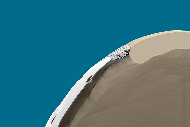
The center of the CeTi is thin and accommodates and expanded brain. It also absorbs a traumatic force as it acts as a crumple zone. The cross-section also shows the peripheral lattice structure that is partially filled by calcium phosphate paste. This fast-setting HA bone substitute strengthens the bond.
Osteoinduction as deep as 5 mm, in channels with a diameter of 500 µm or more, within 3D-printed titanium implants placed in a non-osseous site (ie, the dorsal muscles of beagle dogs) has been demonstrated.2,4 Hence, it is reasonable to biofunctionalize the rim using scaffolds with a diamond unit cell structure ≥500 µm over a few millimeters of width. Sandblasting, large grit, acid etching (SLA) further promote osteoconductivity and soft tissue adhesion. The external surface is micro-shot peened (250-µm Al2O3 broken beads) to obtain a “satin” finish with an average roughness of N7-N10. A highly polished internal surface discourages tissue adhesion.
Titanium is a nonferrous metal with a low atomic weight. It is relatively radiolucent and allows exceptionally clear images to be obtained without significant artifacts on computer tomography and magnetic resonance imaging.11,12 This fact is generally not known to surgeons who often believe that titanium may cause artifacts and signal loss and is therefore not suitable as cranioplasty. The only drawback to titanium is the presence of backscatter radiation when radiotherapy is required postoperatively.
Calcium phosphate paste is converted into HA upon setting. The composition of HA, the crystalline form of calcium phosphate (Ca10(PO4)6(OH)2), which has a Ca/P ratio of 1.67, is comparable to that of bone (Ca/P ratio of 1.71) and causes the accumulation of calcium and phosphate ions, which form the extracellular matrix. The lattice structure should be left predominantly porous so that osteoblastic cells can migrate inside. Pores varying from 40 to 100 µm in diameter are required for osteoblastic tissue growth, and pores at least 200 µm in diameter are needed for a mature osteon to grow. The pores in the lattice structure are destined to house bone regenerating cells, with interconnected pores having a diameter of approximately 500 µm range, which is essential to provide access to nutrients to the cells colonizing the rim. A fully porous HA shell (Custom Bone Service) is brittle and has a low tensile strength. It is therefore prone to breakage during implantation and late post-traumatic fracture (1.68%).13 Dislocation and mobilization occurred in 0.56% due to swelling of the brain and breakage of the anchor stitches.14
In the 1990s, laser lithography (SLA) was used to fabricate full-sized models of a patient’s skull. This defect model was utilized to manually mold a positive template in the defect using dental resin, and the fixation sites were marked. The positive templates were then used to create negative molds made of gypsum. The implants were hand-laminated and shaped by the gypsum molds. The screw fixation holes were created in the polymerized reactive carbon-reinforced resin, with the implant in the defect model. Hence, the location, direction, and length of the screws were determined in a controlled manner (Figure 4).14 With the advent of 3D planning software, the physical defect model, the physical positive template, and the negative mold are replaced by a virtual surface tessellation language defect model, and the CeTi implant and fixation holes are designed using Geomagic Freeform Plus System and a haptic Touch X input device (3D Systems).8 However, the tangential placement of long screws entails the risk of lacerating a diploic or emissary vein, branches of the middle meningeal artery, or granular foveolae, each time with potential complications of epidural hematoma or cerebrospinal fluid leak. It is less risky to use microscrews in the tabula externa to fix the cranial plate (Figure 5).
Figure 4.
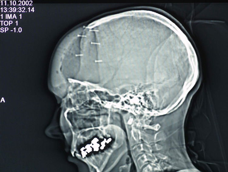
The pocket-hole joinery,7 shown in a lateral skull radiograph.
Figure 5.
Tabs with mono-cortical fixation screws are preferred (see text). PEEK is CNC milled and needs a certain thickness for that reason. Adapting a PEEK plate in the defect on top of edematous brain tissue requires more pulling force. In that case, pocket-hole joinery is recommended. PEEK indicates polyetheretherketone.
The clinically assumed resistance to infection could be explained by the texturized titanium surface and the locally raised levels of free calcium ions. The SLA-texturized titanium surface promotes protein absorption, increases fibroblast differentiation, and increases connective tissue attachment.13,15 The risk for a fluid layer between implant and surrounding tissues is thus reduced. The implant becomes quickly soft tissue integrated rather than encapsulated. Free calcium ions are known to have antibacterial properties.16
The small number in the series and the lack of a comparison group prompt cautious interpretation of our assumptions.
Conclusion
Ceramic 3D-printed titanium cranioplasty has proved its usefulness in selected cases of inlay cranioplasty (alleged allergy to plastics, infected secondary PMMA and PEEK cranioplasties) and voluminous onlay procedures. We recommend further research regarding strain at the fixation site (eg, pocket-hole joinery, lips and perpendicular screws, long-term stress areas after osseointegration using finite element analysis) and clinical follow-up in a larger series.
Acknowledgements
The authors thank Ing Ruben Van de Sande for providing expert advice regarding production and Ir Stijn Huys regarding mechanical properties.
Footnotes
Declaration of Conflicting Interests: The author(s) declared the following potential conflicts of interest with respect to the research, authorship, and/or publication of this article: Dr Mommaerts is innovation manager and co-owner of CADSkills bvba, the company producing the implants.
Funding: The author(s) received no financial support for the research, authorship, and/or publication of this article.
ORCID iD: Maurice Y. Mommaerts, PhD  https://orcid.org/0000-0002-3522-8879
References
- 1. Mommaerts MY. Guidelines for patient-specific jawline definition with titanium implants in esthetic, deformity and malformation surgery. Ann Maxillofac Surg. 2016;6(2):287–291. doi:0.4103/2231-0746.200325 [DOI] [PMC free article] [PubMed] [Google Scholar]
- 2. Fukuda A, Takemoto M, Saito T, et al. Osteoinduction of porous Ti implants with a channel structure fabricated by selective laser melting. Acta Biomater. 2011;7(5):2327–2336. doi:10.1016/j.actbio.2011.01.037 [DOI] [PubMed] [Google Scholar]
- 3. Zhao G, Schwartz Z, Wieland M, et al. High surface energy enhances cell response to titanium substrate microstructure. J Biomed Mater Res Part A. 2005;74(1):49–58. doi:10.1002/jbm.a.30320 [DOI] [PubMed] [Google Scholar]
- 4. de Wilde M, Schumacher R, Mayer K, et al. Bone regeneration by the osteoconductivity of porous titanium implants manufactured by selective laser melting: a histological and micro computed tomography study in the rabbit. Tissue Eng Part A. 2013;19(23-24):2645–2654. doi:10.1089/ten.TEA.2012.0753 [DOI] [PubMed] [Google Scholar]
- 5. Bral A, Mommaerts MY. In vivo biofunctionalization of titanium patient-specific implants with nano hydroxyapatite and other nano calcium phosphate coatings: a systematic review. J Craniomaxillofac Surg. 2016;44(4):400–412. doi:10.1016/j.jcms.2015.12.004 [DOI] [PubMed] [Google Scholar]
- 6. Uskokovic V, Tang S, Nikolic MG, Markovic S, Wu VM. Calcium phosphate nanoparticles as intrinsic inorganic antimicrobials: in search of the key particle property. Biointerphases. 2019;14(3):031001 doi:10.1116/1.5090396 [DOI] [PMC free article] [PubMed] [Google Scholar]
- 7. Rasse M, Lindner A. Reconstruction of calvarial defects with prefabricated carbon fibre implants. J Craniomaxillofac Surg. 1996;24(Suppl 1):92 doi:10.1016/S1010-5182(96)80439-2 8773890 [Google Scholar]
- 8. Nout E, Mommaerts MY. Considerations in computer-aided design for inlay cranioplasty: technical note. Oral Maxillofac Surg. 2018;22(1):65–69. doi:10.1007/s10006-017-0668-4 [DOI] [PMC free article] [PubMed] [Google Scholar]
- 9. Rafi HK, Karthik NV, Gong H, Starr TL, Stucker BE. Microstructures and mechanical properties of Ti6Al4V parts fabricated by selective laser melting and electron beam melting. J Mater Eng Perform. 2013;22(12):3872–3883. doi:10.1007/s11665-013-0658-0 [Google Scholar]
- 10. Vandenbroucke B, Kruth J-P. Selective laser melting of biocompatible metals for rapid manufacturing of medical parts. Rapid Prototyp J. 2007;13(4):196–203. doi:10.1108/13552540710776142 [Google Scholar]
- 11. Chandler CL, Uttley D, Archer DJ, MacVikar D. Imaging after titanium cranioplasty. Br J Neurosurg. 1994;8(4):409–414. [DOI] [PubMed] [Google Scholar]
- 12. Höhne J, Brawanski A, Gassner HG, Schebesch K-M. Feasibility of the custom-made titanium cranioplasty CRANIOTOP®. Surg Neurol Int. 1994;4:803–807. doi:10.1016/j.jcms.2013.01.030 [DOI] [PMC free article] [PubMed] [Google Scholar]
- 13. Stefini R, Esposito G, Zanotti B, Iaccarino C, Fontanella MM, Servadei F. Use of “custom made” porous hydroxyapatite implants for cranioplasty: postoperative analysis of complications in 1549 patients. Surg Neurol Int. 2013;4:12 doi:10.4103/2152-7806.106290 [DOI] [PMC free article] [PubMed] [Google Scholar]
- 14. Saringer W, Nöbauer-Huhmann I, Knosp E. Cranioplasty with individual carbon fibre reinforced polymer (CFRP) medical grade implants based on CAD/CAM technique. Acta Neurochir. 2002;144(11):1193–1203. doi:10.1007/s00701-002-0995-5 [DOI] [PubMed] [Google Scholar]
- 15. Kim H, Murakami H, Chehroudi B, Textor M, Brunette DM. Effects of surface topography on the connective tissue attachment to subcutaneous implants. Int J Oral Maxillofac Implant. 2006;21(3):354–365. [PubMed] [Google Scholar]
- 16. Oates VJ, Wen W, Hamilton DW. Role of titanium surface topography and surface wettability on focal adhesion kinase mediated signaling in fibroblast. Materials. 2011;4(5):893–907. doi: 10.3390/ma4050893 [DOI] [PMC free article] [PubMed] [Google Scholar]


