

Highlights
-
•
Arms down positioning is achievable for proton post-mastectomy radiation therapy.
-
•
Arms down position is dosimetrically comparable to conventional arms up position.
-
•
Arms down position setup is as accurate as the conventional arms up position setup.
-
•
An arms-down contouring atlas has been provided for reproducibility.
Keywords: Pencil beam scanning, Breast, IMPT, Positioning, Setup, Atlas, Proton therapy, PMRT, Post-mastectomy, Treatment planning, Dosimetry
Abstract
Background and purpose
Breast cancer patients receiving radiation are traditionally positioned with both arms up, but this may not be feasible or comfortable for all patients. We evaluated the treatment planning and positioning reproducibility differences between the arms up and arms down positions for patients receiving post-mastectomy radiation therapy (PMRT) using proton pencil beam scanning (PBS).
Materials and methods
Ten PMRT patients who were scheduled to receive PBS underwent CT-based treatment planning in both an arms down and a standard arms up position. An arms down contouring atlas was developed for consistency in treatment planning. Treatment plans were performed on both scans. A Wilcoxon test was applied to compare arms up and arms down metrics across patients. Five patients received treatment in the arms-down position at our institution while others were treated with the arms up. Residual set-up errors were recorded for each patient’s treatment fractions and compared between positions.
Results
Target structure coverage remained consistent between the arms up and arms down positions. In regard to the OAR, the heart mean and maximum doses were statistically significantly lower in the arms up position versus the arms down position, however, the absolute differences were modest. Patients demonstrated similar setup errors, less than 0.5 mm differences, in all directions.
Conclusions
PBS for PMRT in the arms down position appeared stable and reproducible compared to the traditional arms up positioning. The degree of OAR sparing in the arms down group was minimally less robust but still far superior to conventional photon therapy.
1. Introduction
Pencil Beam Scanning (PBS) is increasingly utilized for post-mastectomy breast radiation therapy (PMRT). Using a single field and intensity modulation, PBS-PMRT improves treatment for patients with or without breast reconstruction by achieving appropriate complete target coverage of both the chest wall and the involved nodal regions, in particular the internal mammary lymph nodes, while substantially reducing dose to cardiac/lung structures [1]. It has been demonstrated that the latter correlates with higher risk of future cardiac failure [2]. This treatment has been shown to be adequately robust against both setup uncertainties (±3 mm along each translation axis and ±2° around each rotation axis) and patient breathing motion from quiet respiration [3].
Traditionally, patients receiving conventional photon therapy for breast cancer are positioned on a breast board with both arms up, abducted and externally rotated at the shoulder in order to allow for clearance of the tangent fields. When proton breast treatment was initiated, the same immobilization approach was adopted [4], [5], [6]. For many patients, the arms up position is stable and sufficiently comfortable such that the patient can maintain the position throughout treatment. However, for some patients, the prolonged positioning of the arms up is painful or physically impossible due to prior shoulder injury or as sequelae from breast cancer surgery, e.g. cording from axillary dissection or frozen shoulder after limited movements following breast reconstruction [7], [8]. These patients often require intense physical therapy prior to radiation to regain range of motion sufficient for radiation planning that can cause undue delay to treatment. For this reason, an akimbo position or “arms down” position may be the only positioning choice. Sentinel lymph node biopsy or axillary node dissection, which is standard for any breast surgery for an invasive breast cancer, introduces discomfort for the vast majority of patients with abduction of the arm thus making a radiation position that does not require the arms to be raised above the head an attractive option for most breast cancer patients [9], [10].
For proton treatment, the single en-face field technique allows the use of an arms down position but the dosimetric impact of this position on target coverage and normal tissue sparing has never been evaluated. Likewise, the reproducibility of arms down positioning for daily treatments has not been previously verified. In this study, we conducted both: 1) a treatment planning study of ten patients who were scanned in both the arms up and arms down position to evaluate any treatment planning differences between the arms up and arms down positions which included 2) development of a contouring atlas for women receiving treatment in the arms down position to ensure contouring reproducibility and 3) finally by a positioning reproducibility study of patients clinically treated in the arms down position.
2. Material and methods
2.1. Patient simulation and positioning
Ten patients who required PMRT and were scheduled to receive proton beam radiation at our institution underwent CT-based treatment planning. First, patients were positioned on a breast board at a 30° angle with their arms in the abducted and externally rotated position above their heads with hand grips and arm cups. Arm cups improve arm position and decrease shifts of the chest wall in the craniocaudal direction [11]. For photons, the board angle is chosen in order to get the longitudinal axis of the sternum parallel to the radiation couch [11]. In 360° proton gantry angle, the board angle is a compromise between CT bore size constraints and optimization of the treatment surface angle for patient setup using surface imaging [12]. Additional refinements are used for proton immobilization to further minimize set-up errors: a head and neck head cup to better control the neck position, hand grips, and a chin strap to further immobilize the arm and chin positions.
The same ten patients as simulated above were then positioned in the arms down position, with arms slightly akimbo and handgrips placed to the side of the patient (Fig. 1). A custom cushion was used when needed to further immobilize the elbow in lieu of arm cups. The head position was identical to the arms up position.
Fig. 1.

PMRT patient setup at the time of CT scan. (a) Conventional arms up setup position; (b) novel arms down setup position; in both cases, a chin strap and hand grips are used for positioning reproducibility.
Each patient subsequently underwent two CT scans, one in the arms up and one in the arms down position. Both scans were performed during quiet respiration using a LightSpeed RT16 or Discovery CTR590 RT unit (GE Medical Systems) at 140 kV and 500 mA with 2.5-mm slice thickness.
2.2. Target and normal tissue delineation
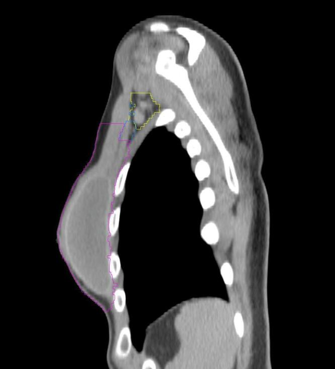
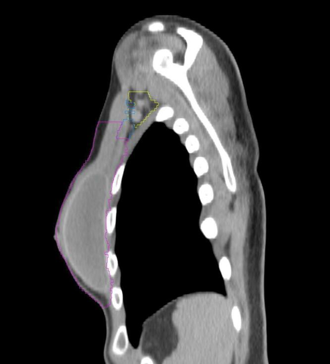
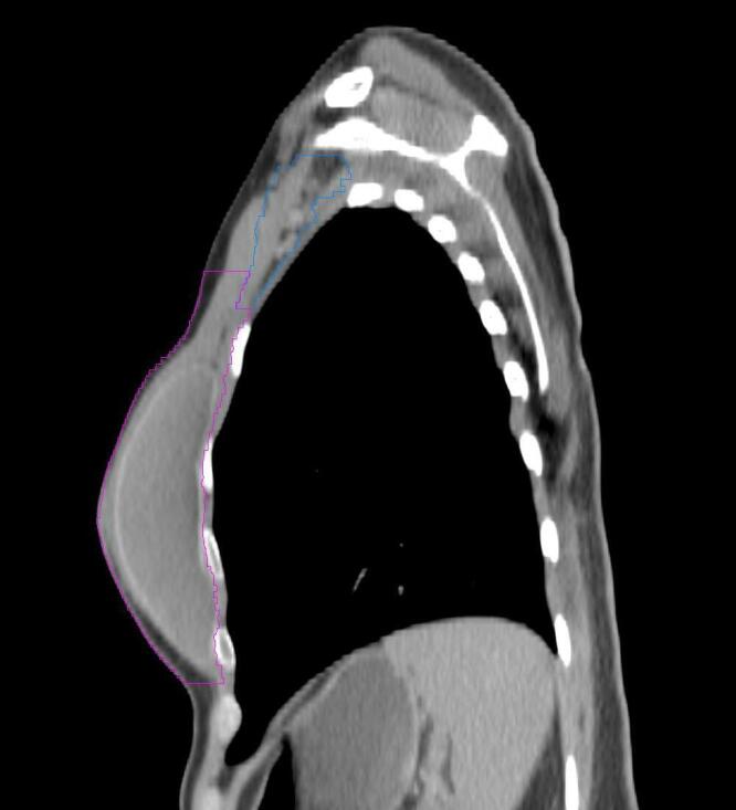
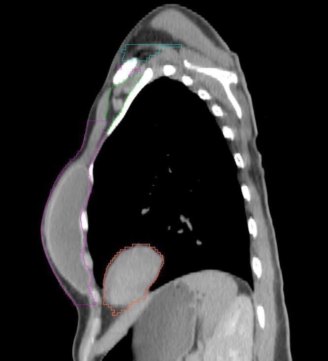
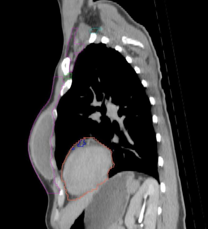
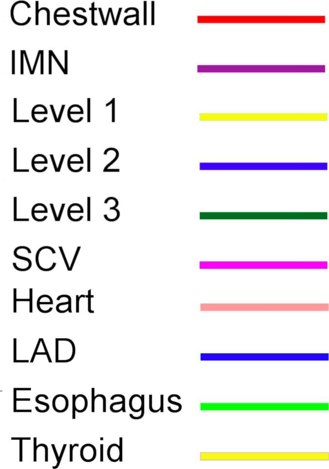
All target structures and organs-at-risk (OAR) were contoured and cross validated by the same two physicians. The target structures included the ipsilateral chest wall inclusive of the breast prosthesis in the case of breast reconstruction, as well as all regional lymph nodes considered at risk for harboring disease including the supraclavicular lymph nodes (SCV), internal mammary lymph nodes through the top of the 4th intercostal space, and the undissected axilla, which included levels 2 and 3 for all patients and level 1 in patients who did not have an axillary dissection. In addition, the heart, left anterior descending coronary artery (LAD), ipsilateral lung, thyroid, and esophagus were all delineated as OAR. All of the contours were delineated using the anatomic definitions defined in the proton contouring atlas for RTOG 3510, also known as the RADCOMP trial. As all existing breast atlas utilize an arms up position, the participating physicians reported the target contouring more challenging for the arms down position. Therefore, in response to this, an arms down atlas was subsequently developed, using the same anatomic landmarks as those in the RADCOMP proton atlas and with consensus agreement between the practicing physicians for those structures that differed most in appearance in the arms down position, e.g. the level 1 axilla (Fig. 2).
Fig. 2.

Four selected representative slices of the arms-down atlas showing the transition of level I-II of the axilla.
2.3. Treatment planning
To ensure a consistent comparison between the arms up and arms down-scans, the treatment planning algorithm specified that priority be placed on overall target coverage after locking OAR sparing. Within the planning algorithm, the following planning constraints were defined: 45 GyRBE mean dose to the chest wall and axillary levels 2 and level 3, supraclavicular, and internal mammary (IMN) nodes followed by a 5.4 GyRBE mean boost to the chest wall and IMN. In addition, the minimum dose to axillary level I, if contoured, was set to 40 GyRBE, and the maximum dose to the chest wall skin (3 mm thickness) to 49 GyRBE. In regard to the OAR, the maximum mean heart dose was locked at 1 GyRBE, the maximum mean LAD dose was 1.5 GyRBE, the maximum mean dose of the ipsilateral lung was 7 GyRBE, the maximum dose to the esophagus was 40 GyRBE, and the maximum dose to the thyroid was 45 GyRBE.
In addition to these planning constraints, the following planning objectives were considered: 1) minimize maximum dose to the patient, 2) minimize underdosing the individual targets at their respective prescription doses (50.4 GyRBE or 45 GyRBE), 3) minimize dose above 45 GyRBE to the axillary level 2 and 3, and the supraclavicular region, and 4) minimize dose above 40 GyRBE to axillary level 1, if contoured. Planning constraints and objectives are summarized in Table 1. Plans were generated using the Astroid planning system (.decimal, LLC). Astroid uses Pareto-surface navigation in order to obtain the most clinically-suitable solution [13]. The PBS machine considered for this work presents a spot size of 3–7 mm as a function of energy (70–MeV). A 45-mm range shifter was employed to ensure potential delivery up to the patient surface. To avoid collision with the patient in the arms up position, a 15+ cm airgap is needed. The same airgap was maintained for the arms down position despite the potential for bringing the snout closer. Once generated with the abovementioned parameters, each plan was navigated to obtain maximal overall target coverage. For each patient, plan quality could then be compared between the different arms positions using various DVH metrics.
Table 1.
Set of planning constraints and objectives.
| Structure | Constraint | Objective(s) |
|---|---|---|
| Chest Wall | minimum mean of 50.4 GyRBE in 28 fractions | minimize underdose to 50.4 GyRBE |
| IMN | minimum mean of 50.4 GyRBE in 28 fractions | minimize underdose to 50.4 GyRBE |
| Axilla level 1* | minimum of 40 GyRBE in 25 fractions | minimize overdose to 40 GyRBE |
| Axilla level 2 | minimum mean of 45 GyRBE in 25 fractions | minimize underdose and overdose to 45 GyRBE |
| Axilla level 3 | minimum mean dose of 45 GyRBE in 25 fractions | minimize underdose and overdose to 45 GyRBE |
| SCV | minimum mean of 45 GyRBE in 25 fractions | minimize underdose and overdose to 45 GyRBE |
| Skin (3 mm) | maximum of 49 GyRBE | |
| Heart | maximum mean of 1 GyRBE | |
| IMN | maximum mean of 1.5 GyRBE | |
| Ipsilateral lung | maximum mean of 7 GyRBE | |
| Esophagus | maximum of 40 GyRBE | |
| Thyroid | maximum of 45 GyRBE | |
| Patient | maximum of 52 GyRBE | minimize maximum dose |
SCV, Supraclavicular; IMN, Intra Mammary Nodes. “GyRBE” here defined with a constant RBE of 1.1.
if present.
2.4. Treatment delivery
Patients were immobilized as detailed above under “Patient Simulation and Positioning.” First, patients were set-up at gantry 0° using lasers and tattoos. A static surface image was then acquired with AlignRT™ software, and shifts applied to match the targets ROI to the one based on planning CT [14]. When the patient position was within 3 mm/2° tolerance, the neck, chin, arms and hips were manually adjusted, and the static surface image process repeated. The final set-up position was then monitored during a few breathing cycles and slightly adjusted if necessary. Finally, the gantry was rotated at the treatment angle of ±300 and the setup position confirmed with X-rays.
Five patients were then clinically treated with their arms down, due to mobility issues. The remaining patients were treated with their arms up as it is the standard procedure in our facility. An institutional research IRB for treatment planning and physics research covers the work in this submission. The patients who received arms down treatment did so out of clinical necessity and none were enrolled on a research protocol for this purpose, therefore, no patient informed consent for altered treatment positioning was obtained or required.
2.5. Treatment planning and delivery evaluation metrics
For the treatment planning portion of the study, the following dose metrics were used to compare each set of plans: 1) dose received by 99% and 90% of the volume for each target structure, 2) the volume of the ipsilateral lung receiving 20 GyRBE, 3) the mean dose to both heart and LAD, and 4) the dose received by 1% of the volume of the heart and thyroid (D1), the dose received to 5 cc of the esophagus (D5cc), and the volume of the lung and LAD receiving at least 5 GyRBE (V5). A Wilcoxon test was subsequently applied to compare the individual arms up and arms down metrics across all ten patients.
For the treatment delivery and positioning portion of the study, the residual set-up errors calculated by the AlignRT™ software were recorded for each of the arms down patient’s treatment fractions and then compared with data previously reported in the literature for arms up patients [9]. The calculated radiographic translations from X-ray confirmation at treatment angle were also analyzed. Finally, to assess position stability, residual set-up errors were also computed on the surface images acquired after treatment for 2 patients.
3. Results
3.1. Treatment planning
Target coverage remained highly consistent between the ten arms up and ten arms down plans (dose metrics, Table 2 dose volume histograms, Fig. 3). For example, the mean D90 of the chest wall was 48.0 GyRBE in the arms up position versus 48.1 GyRBE in the arms down position. Similar coverage was achieved for the SCV (45.8 vs. 45.7 GyRBE up/down), IMN (47.6 vs 47.8 GyRBE up/down), level 2 axillae (47.7 vs 47.4 GyRBE up/down), and level 3 axillae (47.6 vs 47.5 GyRBE up/down). Axillary level I received a modestly lower dose in the arms down position versus the arms up position (mean: 45.5 versus 46.2 GyRBE) but this was not deemed to be statistically significant (Table 2, Fig. 3A). Similar results were observed for D99. In regard to the OAR, both the esophagus and thyroid received slightly lower dose exposure [e.g. <30 GyRBE] in the arms down position, but the mean and maximum doses delivered were not statistically significantly different (Table 2, Fig. 3B). Likewise, the lung V20 and mean lung doses were very similar in the arms up and arms down positions, respectively. The heart mean and D1 doses were statistically significantly lower in the arms up position versus the arms down position, e.g. a mean of 0.7 versus 0.9 GyRBE and a D1 of 13.1 versus 20.4 GyRBE in the arms up and arms down positions, respectively, however the absolute difference in mean cardiac dose was modest (Table 2, Fig. 3B).
Table 2.
Median Dosimetric Information and Wilcoxon signed rank test.
| Target Structure | Dose (GyRBE) | Arms up | Arms down | Difference | W-value* |
|---|---|---|---|---|---|
| Chest wall | D99 | 43.2 | 43.6 | 0.4 | 26 |
| D90 | 48.1 | 48.1 | 0.0 | 16 | |
| mean | 50.4 | 50.4 | 0.0 | 18 | |
| SCV | D99 | 43.8 | 42.4 | −1.5 | 12 |
| D90 | 45.6 | 45.7 | 0.1 | 24 | |
| mean | 48.1 | 48.4 | 0.2 | 19 | |
| IMN | D99 | 46.1 | 41.4 | −4.7 | 17 |
| D90 | 48.6 | 47.5 | −1.0 | 17 | |
| mean | 50.4 | 50.4 | 0.0 | 20 | |
| Level I | D99 | 45.3 | 44.0 | −1.3 | 4 |
| D90 | 46.4 | 45.6 | −0.8 | 6 | |
| mean | 48.1 | 47.6 | −0.5 | 6 | |
| Level II | D99 | 46.0 | 46.0 | 0.0 | 26 |
| D90 | 47.7 | 47.7 | −0.1 | 19 | |
| mean | 49.5 | 49.3 | −0.2 | 13 | |
| Level III | D99 | 45.6 | 46.0 | 0.4 | 22 |
| D90 | 47.3 | 47.7 | 0.4 | 27 | |
| mean | 49.2 | 49.5 | 0.2 | 24 | |
| LAD | V5 (%) | 3.0 | 5.4 | 2.4 | 14 |
| Mean | 1.4 | 1.3 | 0.0 | 22 | |
| Heart | D1 | 13.9 | 22.6 | 8.7 | 0+ |
| Mean | 0.7 | 1.0 | 0.2 | 1+ | |
| Ipsilateral Lung | V5 (%) | 34.4 | 34.2 | −0.2 | 15 |
| V20 (%) | 13.6 | 13.3 | −0.4 | 12 | |
| Mean | 7.0 | 7.0 | 0.0 | 11 | |
| Thyroid | D1 | 43.7 | 43.7 | 0.0 | 22 |
| Esophagus | D5cc | 16.9 | 16.7 | −0.3 | 19 |
SCV, Supraclavicular; IMN, Intra Mammary Nodes; LAD, left anterior descending coronary artery.
alpha = 0.05, n = 10 (except for level 1, n = 7), critical value = 8 (except for level 1, critical value = 2).
significant.
Fig. 3.

A) Average Dose Volume Histogram of Target Structures and B) Organs-at-Risk for ten patients in the arms up (solid lines) or arms down (dash lines) position.
3.2. Treatment delivery
Overall, patients demonstrated similar systematic and random setup errors in the arms down and arms up positions for the vertical (1.0 ± 0.5 mm vs 1.3 ± 0.5 mm), longitudinal (0.6 ± 0.7 mm vs 0.8 ± 0.7 mm) and lateral directions (1.4 ± 1.2 mm vs 1.5 ± 1.1 mm) (Table 3). The calculated radiographic translations obtained by comparing the position of skin markers to those on DRRs were also analyzed. Four of the five patients treated in the arms down position presented a maximum of four calculated radiographic corrections >3 mm over their 28 total treatment fractions. The fifth patient presented 11 calculated radiographic corrections >3 mm after positioning with AlignRT™. Six occurred in the lateral direction for the last six fractions for an average of 4.5 mm. In comparison, 30% of the patients treated in the institution with the arms up position had >7 calculated radiographic corrections >3 mm over their 28 total treatment fractions. A pattern that was also observed was a large number of radiographic corrections occurring towards the end of the treatment. For arms down, a maximum difference of 1.1 mm in translation and 1° in rotation was found between the setup errors computed before and after treatment delivery. For arms up, the patient position changes less than 1.5 mm for translations and less than 0.60 for rotations.
Table 3.
Positioning residual setup errors calculated by the AlignRT™ software for patient treated arms down (left) and arms up (right).
| (mm) | Arms Up |
Arms Down |
||||
|---|---|---|---|---|---|---|
| Systematic errors (average, SD) |
Random errors (average) |
Systematic errors (average, SD) |
Random errors (average) |
|||
| VRT | 1.3 | 0.5 | 1.3 | 1.0 | 0.5 | 1.2 |
| LNG | 0.8 | 0.7 | 1.2 | 0.6 | 0.7 | 1.1 |
| LAT | 1.5 | 1.1 | 1.4 | 1.4 | 1.2 | 1.5 |
| YAW | 0.5 | 0.4 | 0.9 | 0.6 | 0.6 | 0.7 |
| ROLL | 0.6 | 0.4 | 0.6 | 0.7 | 0.6 | 0.6 |
| PITCH | 0.4 | 0.4 | 0.6 | 0.6 | 0.4 | 0.5 |
VRT, Vertical; LNG, Longitudinal; LAT, Lateral.
4. Discussion
To our knowledge, this is the first paper to discuss the benefits of supine, arms down positioning for breast radiotherapy among patients receiving proton pencil beam scanning. In this two-phase study of patients planned and treated with proton beam radiation for breast cancer in the arms up versus arms down position, we found a high rate of fidelity both in treatment planning and daily patient set-up. A contouring atlas for the arms down position was also developed and utilized to ensure consistent anatomic volumes between the different patient positions.
The physical properties inherent to proton beam radiation and to PBS in particular, allow for adequate target coverage in non-traditional patient immobilizations without increasing the risk of normal tissue toxicity. Indeed, the treatment plans generated for patients in the arms down position were extremely similar in treatment planning quality and robustness to the same patients simulated in the arms up position. While the cardiac metrics were statistically significantly lower in the arms up position, the absolute magnitude of difference was small, unlikely to be clinically significant, and remain far superior to photon dosimetry techniques.
While there is a paucity of data regarding alternative positioning for breast cancer therapy, there have been some reports of utilizing both lateral decubitus and prone positioning for breast cancer patients requiring adjuvant radiation. [9], [10], [16] Decubitus positioning has been limited to patients who do not require treatment of the regional lymph nodes as was required in our patient population, though it does permit for a potentially more comfortable arm position in those with recent surgery. In contrast, prone positioning as described by Boute and colleagues does permit for adequate target dosing to the regional lymph nodes, while simultaneously permitting the ipsilateral arm to be below the patient’s head. Speelers and colleagues performed a treatment planning study evaluating ten patients treated in either the supine arms up or prone “crawl” (ipsilateral arm down) position, and planned with either photon or pencil beam proton radiation [17]. They found similar target coverage with both the supine and prone positions and with relative sparing of the heart and lungs with proton-based techniques. They similarly showed minimal differences in OAR dosing between the proton supine arms up and the prone “crawl” position, save for a small difference in the mean LAD and mean lung dose, favoring the prone position. However, as this was purely a treatment planning study and patients did not receive treatment with protons in an arms down position, we are unable to glean insights regarding the set-up reproducibility of such an approach. Additionally, the authors acknowledged the lack of contouring guidelines for this alternative crawl position and the need for extrapolation from existing guidelines, underscoring the value of a contouring atlas for alternative patient positioning techniques.
As earlier mentioned, it is to be noted that our physicians also reported the target contouring more challenging for the arms down position. The position of these structures compared to OAR was not studied in this paper. However, Kirova et al. reported no significant differences in depth between arms up and arms down position for the region of I, II and III ribs interspaces and no difference in the lateral limit of the IMN [15]. The authors attempted to minimize variability in contouring by developing an arms down atlas, which continues to be referenced clinically for our proton patients treated in the supine arms down position. This arms down atlas was developed with reliance on the lymph node definitions previously delineated for the RTOG breast atlas to ensure consistency across atlases even as patient positioning was altered. We make this atlas readily available in this publication for those wishing to utilize a similar practice (Supplement A).
Additionally, among the five patients who subsequently received proton beam treatment in the supine arms down position, daily positioning was similarly precise and accurate compared to the traditional arms up positioning using our previously described combination of tattoos, AlignRT™ and radiographic imaging [12], [14]. These findings suggest that patients receiving PBS-PMRT have the option of being treated in the arms down position, potentially sparing undue delays to treatment after axillary surgery. Anecdotally, in performing this study, participants uniformly preferred the arms down position and several asked to be treated in that position for their actual radiation treatments despite the ability to raise their arms above their heads. Most described the arms down position as more comfortable and reported that they felt less exposed and vulnerable with their arms down.
Treatment planning was performed, per the institution guidelines, with a single en-face ±300 field and with a large air gap. Other institutions may use a different approach with multiple fields. Nonetheless, similar findings are expected with such approaches as they consist of en-face fields generally ranging from 0 to ±600. An arms-down position may permit a reduction in the air gap at some institutions, hence slightly better dosimetry from the reduced geometric spread of the beam through the range shifter.
Despite finding robust treatment planning and delivery with the arms down position and the potential benefits to patients evident in this study, the treatment planning portion of the study did not evaluate the issue of spot size. There is the possibility that the use of a larger or smaller spot size could alter the dosimetric equivalence between the arms up and arms down patients observed in our study. If such difference were to be found, their clinical significance would need to be further evaluated. In addition, for the treatment set-up portion of the study, the observation of the arms down position was limited to five patients and it is possible that a larger sample size could have demonstrated more variability in daily positioning than what was observed.
It should be noted that this study considers only postmastectomy patients with or without breast reconstruction. While results may apply to some patients with intact breasts, large breasted patient would be challenging to treat in an arms down position due to the difficulty of adequately separating the ipsilateral arm from a ptotic breast.
In conclusion, in this treatment study of patients receiving PBS-PMRT, the arms down position appeared to be both stable and reproducible compared to the traditional arms up positioning. When comparing the same degree of target coverage between the two position cohorts, the degree of OAR sparing in the arms down group was minimally less robust compared to the arms up group, but it was still acceptable and far superior to conventional photon therapy.
5. Summary
Pencil beam scanning for post-mastectomy radiation therapy in the arms down position appears equivalent and as reproducible compared to the traditional arms up positioning in terms of treatment planning and setup.
Funding
The author(s) received no financial support for the research, authorship, and/or publication of this article.
Declaration of Competing Interest
The authors declare that they have no known competing financial interests or personal relationships that could have appeared to influence the work reported in this paper.
Footnotes
Supplementary data to this article can be found online at https://doi.org/10.1016/j.phro.2020.04.003.
Appendix A. Supplementary data
The following are the Supplementary data to this article:
Supplementary figure 1.

Supplementary figure 2.

Supplementary figure 3.

Supplementary figure 4.
Supplementary figure 5.
Supplementary figure 6.
Supplementary figure 7.
Supplementary figure 8.
Supplementary figure 9.

Supplementary figure 10.

Supplementary figure 11.

Supplementary figure 12.

Supplementary figure 13.

Supplementary figure 14.

Supplementary figure 15.

Supplementary figure 16.

Supplementary figure 17.

Supplementary figure 18.

Supplementary figure 19.

Supplementary figure 20.

Supplementary figure 21.

Supplementary figure 22.

Supplementary figure 23.

Supplementary figure 24.

Supplementary figure 25.

Supplementary figure 26.

Supplementary figure 27.

Supplementary figure 28.

Supplementary figure 29.

Supplementary figure 30.

Supplementary figure 31.

Supplementary figure 32.

Supplementary figure 33.

Supplementary figure 34.

Supplementary figure 35.

Supplementary figure 36.

Supplementary figure 37.

Supplementary figure 38.

Supplementary figure 39.

Supplementary figure 40.

Supplementary figure 41.

Supplementary figure 42.

Supplementary figure 43.

Supplementary figure 44.

Supplementary figure 45.

Supplementary figure 46.

Supplementary figure 47.

Supplementary figure 48.

Supplementary figure 49.

Supplementary figure 50.

Supplementary figure 51.

Supplementary figure 52.

Supplementary figure 53.

Supplementary figure 54.

Supplementary figure 55.

Supplementary figure 56.

Supplementary figure 57.

Supplementary figure 58.

Supplementary figure 59.

Supplementary figure 60.

Supplementary figure 61.

Supplementary figure 62.

Supplementary figure 63.
References
- 1.Jimenez R.B., Goma C., Nyamwanda J., Kooy H.M., Halabi T., Napolitano B.N. Intensity modulated proton therapy for postmastectomy radiation of bilateral implant reconstructed breasts: a treatment planning study. Radiother Oncol. 2013;107(2):213–217. doi: 10.1016/j.radonc.2013.03.028. [DOI] [PubMed] [Google Scholar]
- 2.Darby S.C., Ewertz M., McGale P., Bennet A.M., Blom-Goldman U., Brønnum D. Risk of ischemic heart disease in women after radiotherapy for breast cancer. N Engl J Med. 2013;368(11):987–998. doi: 10.1056/NEJMoa1209825. [DOI] [PubMed] [Google Scholar]
- 3.Patel S.A., Lu H.M., Nyamwanda J.A., Jimenez R.B., Taghian A.G., MacDonald S.M. Postmastectomy radiation therapy technique and cardiopulmonary sparing: a dosimetric comparative analysis between photons and protons with free breathing versus deep inspiration breath hold. Pract Radiat Oncol. 2017;7(6):e377–e384. doi: 10.1016/j.prro.2017.06.006. [DOI] [PubMed] [Google Scholar]
- 4.MacDonald S.M., Patel S.A., Hickey S., Specht M., Isakoff S.J., Gadd M. Proton therapy for breast cancer after mastectomy: early outcomes of a prospective clinical trial. Int J Radiat Oncol Biol Phys. 2013;86(3):484–490. doi: 10.1016/j.ijrobp.2013.01.038. [DOI] [PubMed] [Google Scholar]
- 5.Depauw N., Batin E., Daartz J., Rosenfeld A., Adams J., Kooy H. A novel approach to postmastectomy radiation therapy using scanned proton beams. Int J Radiat Oncol Biol Phys. 2015;91(2):427–434. doi: 10.1016/j.ijrobp.2014.10.039. [DOI] [PubMed] [Google Scholar]
- 6.Jimenez R.B., Hickey S., DePauw N., Yeap B.Y., Batin E., M.A. Gadd Phase II study of proton beam radiation therapy for patients with breast cancer requiring regional nodal irradiation. J Clin Oncol. 2019;37(30):2778–2785. doi: 10.1200/JCO.18.02366. [DOI] [PMC free article] [PubMed] [Google Scholar]
- 7.Yang S., Park D.H., Ahn S.H., Kim J., Lee J.W., Han J.Y. Prevalence and risk factors of adhesive capsulitis of the shoulder after breast cancer treatment. Support Care Cancer. 2017;25(4):1317–1322. doi: 10.1007/s00520-016-3532-4. [DOI] [PubMed] [Google Scholar]
- 8.O’Toole J., Miller C.L., Specht M.C., Skolny M.N., Jammallo L.S., Horick N. Cording following treatment for breast cancer. Breast Cancer Res Treat. 2013;140(1):105–111. doi: 10.1007/s10549-013-2616-9. [DOI] [PMC free article] [PubMed] [Google Scholar]
- 9.Krhili S., Coste E., Xu H.P., Kirova Y.M. Whole breast radiotherapy in the isocentric lateral decubitus position: role of the immobilization device and table on clinical results. Cancer Radiother. 2019;23(3):209–215. doi: 10.1016/j.canrad.2018.09.001. [DOI] [PubMed] [Google Scholar]
- 10.Boute B., DeNeve W., Speleers B., Van Greveling A., Monten C., Van Hoof T. Potential benefits of crawl position for prone radiation therapy in breast cancer. J Appl Clin Med Phys. 2017;18(4):200–205. doi: 10.1002/acm2.12118. [DOI] [PMC free article] [PubMed] [Google Scholar]
- 11.Thilmann C., Adamietz I.A., Saran F., Mose S., Kostka A., Böttcher H.D. The use of a standardized positioning support cushion during daily routine of breast irradiation. Int J Radiat Oncol Biol Phys. 1998;41(2):459–463. doi: 10.1016/s0360-3016(98)00022-4. [DOI] [PubMed] [Google Scholar]
- 12.Batin E., Depauw N., MacDonald S., Lu H.M. Can surface imaging improve the patient setup for proton postmastectomy chest wall irradiation? Pract Radiat Oncol. 2016;6(6):e235–e241. doi: 10.1016/j.prro.2016.02.001. [DOI] [PubMed] [Google Scholar]
- 13.Kooy H.M., Clasie B.M., Lu H.M., Madden T.M., Bentefour H., Depauw N. A case study in proton pencil-beam scanning delivery. Int J Radiat Oncol Biol Phys. 2010;76(2):624–630. doi: 10.1016/j.ijrobp.2009.06.065. [DOI] [PubMed] [Google Scholar]
- 14.Batin E., Depauw N., Jimenez R.B., MacDonald S., Lu H.M. Reducing X-ray imaging for proton postmastectomy chest wall patients. Pract Radiat Oncol. 2018;8(5):e266–e274. doi: 10.1016/j.prro.2018.03.002. [DOI] [PubMed] [Google Scholar]
- 15.Kirova Y.M., Servois V., Campana F., Dendale R., Bollet M.A., Laki F. CT-scan based localization of the internal mammary chain and supra clavicular nodes for breast cancer radiation therapy planning. Radiother Oncol. 2006;79(3):310–315. doi: 10.1016/j.radonc.2006.05.014. [DOI] [PubMed] [Google Scholar]
- 16.Kirova Y.M., Hijal T., Campana F., Fournier-Bidoz N., Stilhart A., Dendale R. Whole breast radiotherapy in the lateral decubitus position: a dosimetric and clinical solution to decrease the doses to the organs at risk (OAR) Radiother Oncol. 2014;110(3):477–481. doi: 10.1016/j.radonc.2013.10.038. [DOI] [PubMed] [Google Scholar]
- 17.Speleers B., Belosi F., Gersem W., Deseyne P., Paelinck L., Bolsi A. Comparison of supine or prone crawl photon or proton breast and regional lymph node radiation therapy including the internal mammary chain. Sci Rep. 2019;9:4755. doi: 10.1038/s41598-019-41283-1. [DOI] [PMC free article] [PubMed] [Google Scholar]
Associated Data
This section collects any data citations, data availability statements, or supplementary materials included in this article.