Abstract
In lead optimization, protein crystallography is an indispensable tool to analyze drug binding. Binding modes and non‐covalent interaction inventories are essential to design follow‐up synthesis candidates. Two protocols are commonly applied to produce protein–ligand complexes: cocrystallization and soaking. Because of its time and cost effectiveness, soaking is the more popular method. Taking eight ligand hinge binders of protein kinase A, we demonstrate that cocrystallization is superior. Particularly for flexible proteins, such as kinases, and larger ligands cocrystallization captures more reliable the correct binding pose and induced protein adaptations. The geometrical discrepancies between soaking and cocrystallization appear smaller for fragment‐sized ligands. For larger flexible ligands that trigger conformational changes of the protein, soaking can be misleading and underestimates the number of possible polar interactions due to inadequate, highly impaired positions of protein amino‐acid side and main chain atoms. Thus, if applicable cocrystallization should be the gold standard to study protein–ligand complexes.
Keywords: Crystal structure analysis, soaking, cocrystallization, binding mode analysis, drug design and optimization, interaction inventory, kinases, PKA, trypsin
Lead optimization needs information about binding modes, best from protein crystallography. Cocrystallization and soaking are two protocols to obtain diffracting crystals of protein–ligand complexes. The latter is more popular due to its time and cost effectiveness, but cocrystallization captures the correct binding pose more reliably, particularly of larger and more flexible ligands, as our comparative analysis shows. For fragment‐sized ligands the differences appear negligible.

Introduction
Undoubtedly, X‐ray crystallography is the most powerful method to elucidate the binding pose of ligands bound to proteins even for very weak binders such as low‐molecular‐weight fragments of less than 200 Da.[ 1 , 2 ] As such, the method serves as indispensable source of information in structure‐based drug design. In the past, crystallography has been rated as too slow and cumbersome to routinely accompany drug discovery and optimization projects. Recent improvements at synchrotron X‐ray sources, supported by automatized sample preparation and data collection facilities and sample exchanger equipment enable data collection of more than 200 datasets per day.[ 3 , 4 , 5 ] Accordingly, this major leap in data collection technology reliefs the bottleneck and makes timely structure determinations possible. However, it shifts the challenge back to sample preparation. With the achievable data collection speed, the handling of many crystals with multiple ligand candidates during initial lead finding and subsequent optimization becomes increasingly feasible and popular.
In principle, two strategies can be followed to prepare crystals for data collection of appropriate protein‐ligand complex structures. The first technique, named cocrystallization starts with the exposure of a ligand molecule to the protein in solution and from this solution mixture the protein‐ligand complex is crystallized. Since crystallizations can take from some days to several weeks, this process can be rather elaborate and tedious. Even though crystallization conditions must be established in advance and are usually applied unchanged as initial conditions for the crystallization of the individual protein–ligand complexes, the success of crystallization is difficult to estimate and usually favorable outcome or failure can only be assessed after a long enough crystallization trial period.
The second more appealing and therefore commonly applied procedure is the so‐called soaking protocol. Here, pre‐manufactured protein crystals are exposed to a solution containing the ligand to be studied for protein binding. Since protein crystals contain up to 70 % of water, usually large channels pass through the crystalline packing of the assembled protein molecules and small molecules can diffuse through these channels. In case, the ligand exhibits sufficiently large binding affinity to a depression on the protein surface, it can populate in well‐ordered fashion in this region and shows up in the difference density of the diffraction data collected on such crystals. This method described as crystal soaking appears as a very promising approach to rapidly characterize fragment binding via a crystallographic strategy directly applied on protein crystals.
However, also the soaking technique is not without problems. Even though the diffusion of small molecular probes into protein crystals should be very fast, requiring perhaps only a fraction of a second, cases have been reported where soaking needs hours or even days to fully populate a ligand in a binding pocket of the protein. This observation clearly indicates that not only affinity but also diffusion kinetics into the crystals are important for successful soaking. Consequently, beyond the concentration also the soaking time of the exposed ligand is an important factor to adjust. [6]
Since binding is studied to pre‐manufactured crystals, the question remains to what extend the already crystallized protein can adapt to the binding of the ligand to be soaked. The current study focuses on the comparison of the two popular protocols, soaking and cocrystallization, to produce crystals of protein−ligand complexes. For our case study, we selected the cAMP‐dependent protein kinase (PKA) shown in Figure 1, a typical representative of the clinically highly relevant class of protein kinases. [7] In the current context, kinases are in particular interesting as they are known to be highly flexible proteins and probable induced‐fit adaptations can be triggered by the bound ligands.[ 8 , 9 , 10 ] Kinases exhibit the so‐called glycine‐rich loop (Gly‐loop, see Figure 1) covering the active site, which can adopt multiple conformations. [11] We will show that results from soaking experiments bear the risk to not only falsely represent the experienced protein–ligand interaction patterns and adopted deviating protein conformations in comparison to the biologically relevant geometry under solution conditions but even affect the ligand orientation in the active site. Obviously, the applied crystallization protocol takes impact on the conformational changes experienced by the protein upon ligand accommodation. Importantly, the amount of structural deviations between soaking and cocrystallization seems to increase with the size and conformational flexibility of the studied ligand. This clearly advocates for the fast and straightforward soaking protocol to investigate small and rigid binders such as fragments, whereas for larger ligands, particular in the lead optimization phase where molecular design considerations highly rely on accurate structural data, cocrystallization protocols appear to be more advisable to exert.
Figure 1.
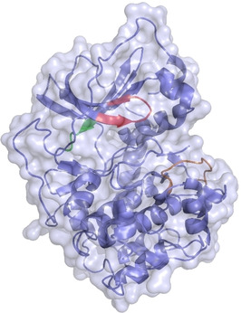
Catalytic subunit of the cAMP‐dependent protein kinase A from Cricetulus griseus (6YNT). It consists of a small and a large lobe, which are connected with each other through the hinge region (green). ATP binds next to this region as natural substrate, which has been omitted for clarity. Above the ATP binding site the very flexible glycine‐rich loop (red) is found. Another important motif is the activation loop (orange) which can be present in an opened or closed state.
Results
To tackle the above‐mentioned issue, we analyzed a series of ligands that are derived from the approved drug fasudil (1, Figure 2) in complex with PKA. All ligands occupy the adenosine triphosphate (ATP) binding site next to the so‐called hinge region. Furthermore, all studied complexes contain in addition a peptidic kinase inhibitor (PKI) that blocks the binding site of the protein substrate to be phosphorylated but it does not interfere with the ATP‐binding pocket. The considered ligands differ in size as well as in their ability to trigger induced‐fit adaptations of the protein. For the comparative analysis, both, cocrystals as well as soaked crystals were prepared and subjected to crystal structure determination.
Figure 2.

Overview of ligands used in this study. Ligand 1 is fasudil and 2, its amino analog. 3: a methylated form of fasudil. 4: Open‐chain N‐(2‐aminoethyl)‐N‐propylisoquinoline‐5‐sulfonamide. 5: Long‐chain N‐[2‐(propylamino)ethyl] isoquinoline‐5‐sulfonamide. 6: short chained N‐(2‐aminoethyl) isoquinoline‐5‐sulfonamide. 7: fragment‐sized methylated N‐methylisoquinoline‐5‐sulfonamide. 8: 1,7‐naphthyridin‐8‐amine.
Fasudil, and seven structurally related ligands were used in this comparative study. For each ligand complex, a diffraction dataset was collected using both, a soaked and cocrystallized specimen, resulting in a total of 16 structures. The individual structures vary in resolution between 1.37–2.01 Å with no significant resolution advantage for structures obtained either by the soaking (mean 1.58 Å) or cocrystallization (mean 1.59 Å) protocol. The mutual superimpositions of the respective structural pairs showing the same bound ligand each time are displayed in Figures 3–10. The corresponding electron densities of the bound ligands are displayed in Figure S1 and S2 in the Supporting Information (SI).
Figure 3.
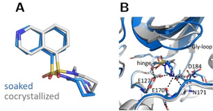
Crystal structures of fasudil (1) in complex with PKA from a soaked (blue, PDB‐code: 6YNA) and cocrystallized crystal (gray, PDB‐code: 5LCP). A: Ligand superposition indicates a slight rotation of the ligand between both structures (RMSD ligand: 1.0 Å, RMSD of the Cα atoms of the hinge region: 0.5 Å). B: Active site superposition. Dotted lines indicate hydrogen bonds. The Gly‐rich loop is positioned with a more open geometry in the cocrystal structure and the latter structure shows more hydrogen bonds between the ligand and PKA.
Figure 10.

Crystal structures of the fragment 1,7‐naphthyridin‐8‐amine (8) in complex with PKA determined with a soaked (brown, PDB‐code: 6YNR) and cocrystallized sample (gray, PDB‐code: 6Y2O). A: Ligand superposition indicates a perfect overlay in both structures (RMSD ligand: 0.1 Å, RMSD of the Cα atoms of the hinge region: 0.2 Å). B: Active site superposition with dotted lines indicating hydrogen bonds. The position of the Gly‐rich loop is identical in both structures and the same hydrogen‐bond pattern is established between ligand and protein. The only difference is a slight shift of Thr183 in the cocrystallized case. This is responsible for the interaction to the endocyclic nitrogen within the ligand of the cocrystallized example.
Figure 3 depicts fasudil (1) in complex with PKA. The position of the glycine‐rich loop is more open in the cocrystallized structure. In particular, this affects the residues Gly50 to Ser53, where backbone atoms are approximately shifted by 2 Å. Concerning the ligand's homopiperazine moiety, deviations mainly result from distinct ring conformations adopted in the two cases. The root‐mean‐square deviation (RMSD) of the ligands between both structures amounts to 1.0 Å. A lower value of 0.5 Å is found for the Cα atoms of the hinge region, where the ligands are bound. A comparison of the RMSD deviations between soaked and cocrystallized ligands in dependence of the sets of coordinates used as reference to align the structures are assembled in Table S4 and S5 in the SI. Nevertheless, it should be noted that RMSD values can average out coordinate differences, thus a direct comparison of torsion angles along, e.g., the seven‐membered ring and further down for 4, 5, and 6 of individual rotamers are more conclusive. The two homopiperazine conformers give rise to deviating hydrogen‐bonding patterns formed with the neighboring protein residues. In fact, the cocrystallized structure displays more polar interactions and involves Asp184 and Glu170 whereas the soaked structure suggests an H‐bond to Asn171.
The crystal structure of amino fasudil 2 is shown in Figure 4. Similarly to 1, the amino analog matches well with the isoquinoline portion but shows a slight deviating orientation of the homopiperazine ring. In the cocrystallized structure, two alternative conformations with identical occupancies of the seven‐membered ring are found. Of these two, one shows the same conformation as in the soaked structure, the second adopts a different conformation in soaked and cocrystallized structure (RMSD: 0.6; 0.7 Å). The spatial shift, however, allows formation of two water mediated H‐bonds to Asn171 and Asp184 only in the soaked structure.
Figure 4.
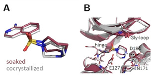
Crystal structures of amino fasudil 2 in complex with PKA determined from a soaked (violet, PDB‐code: 6YNT) and cocrystallized crystal (gray, PDB‐code: 6Y8C). The homopiperazine ring adopts two conformers in the cocrystallized structure. (A) Ligand superposition indicates a slight shift of the ligand between both structures (RMSD ligand: 0.6; 0.7 Å, RMSD of the Cα atoms of the hinge region: 0.5 Å). (B) Active‐site superposition with dotted lines indicating hydrogen bonds. The orientation of the Gly‐loop is slightly different between the two complexes. The ligand interacts with the hinge in both cases, whereas a water molecule mediates interactions to Asp184 and Asn171 only in the structure obtained from the soaked crystal.
Figure 5 shows the binding modes for ligand 3. Here, the positions of the ligand match closer as for ligand 1 (RMSD: 0.7 Å). The position of the Gly‐rich loop is not fully defined in the electron density for the soaked structure. Nonetheless, the amino‐acid residues of the loop, visible in both structures, share common positions. The mean RMSD of the Cα atoms of the protein at the hinge region is 0.3 Å. In contrast to 1, but similar to 2, the spatial positions and adopted conformations of the homopiperazine moiety exhibit similar orientations in the current case.
Figure 5.
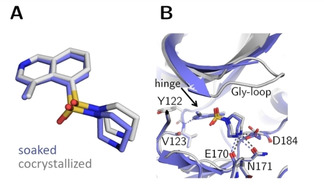
Crystal structures of methylated fasudil 3 in complex with PKA determined from a soaked (blue, PDB‐code: 6YQK) and cocrystallized crystal (gray, PDB‐code: 5M6Y). (A) Structural superposition indicates a slight rotation of the ligand between both cases (RMSD ligand: 0.7 Å, RMSD of the Cα atoms of the hinge region: 0.3 Å). (B) Active site superposition. Dotted lines indicate hydrogen bonds. The position of the Gly‐rich loop is not visible for the soaked crystal structure. The hydrogen‐bonding pattern is similar in both complex structures.
The observation of a partially disordered Gly‐rich loop in the soaked crystal structure is also experienced for ligand 4 (Figure 6). In addition, a deviating position is adopted by the aminoethyl substituent in both complexes. In consequence, a strongly deviating interaction pattern of the ligand's aminoethyl‐nitrogen is found with the protein in the crystal structures resulting from the different crystallization protocols.
Figure 6.
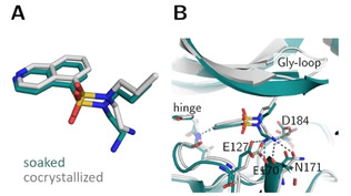
Crystal structures of open chain fasudil‐derivative 4 in complex with PKA from a soaked (teal, PDB‐code: 6YQJ) and cocrystallized structure (gray, PDB‐code: 5LCR). (A) Ligand superposition indicates a slight shift of the entire ligand as well as an altered position of the aminoethyl moiety in the two structures (RMSD ligand: 0.9 Å, RMSD of the Cα atoms of the hinge region: 0.4 Å). (B) Active site superposition. Dotted lines indicate hydrogen bonds. The position of the Gly‐rich loop is not visible in the soaked crystal structure. The hydrogen‐bonding pattern differs between the structures obtained by the two protocols. In the cocrystal structure hydrogen bonds are formed to the hinge, the side chains of Asp184 and Asn171 and the backbone of Glu170. In the soaked structure only the hinge and the backbone of Glu170 are involved in H‐bonding and an additional hydrogen bond is established to the side chain of Glu127 in the soaked structure.
The most prominent differences between soaked and cocrystallized structure were observed for ligands 5 and 6. Both share a common binding mode. In the cocrystallized complex with 5 (Figure 7) a strong spatial shift provokes a downwards movement of the Gly‐rich loop. This shift is triggered by the formation of a hydrogen bond between the ligand and Thr51 of the protein. It is absent in the soaked crystal structure. This in turn leads to an altered position of the ligand, where the sulfonamide adopts an alternative rotamer. The angle between the plane through the atoms of the isoquinoline moiety and the sulfonamide nitrogen is a suitable descriptor for this rotation. For the soaked structure, this angle is 94° while it is only 26° with similar orientation for the ligand found in the cocrystallized structure. The very same observation is made for 6 (Figure 8). In this structure, the differences between the soaked and cocrystallized structure are even more pronounced. The rotated sulfonamide (angle between isoquinoline plane and the sulfonamide nitrogen bond vectors is 25° for cocrystallized and 103° for soaked crystal, thus similarly to the situation observed for 5) is accompanied by a movement of the aminoethyl moiety, which points in both cases in opposite directions. Nevertheless, in both structures resulting from soaking and cocrystallization, there are three hydrogen bonds formed to the protein.
Figure 7.
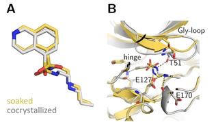
Crystal structures of long‐chain fasudil derivative 5 in complex with PKA obtained from a soaked (yellow, PDB‐code: 6YQI) and cocrystallized specimen (gray, PDB‐code: 5LCQ). (A) Ligand superposition indicates the transformation to an alternative rotamer of the sulfonamide portion with a different placement of the attached substituent in the two structures (RMSD ligand: 0.9 Å, RMSD of the Cα atoms of the hinge region: 0.4 Å). (B) Active site superposition. Dotted lines indicate hydrogen bonds. The position of the Gly‐rich loop is not entirely defined for the soaked structure. Strikingly, the positions of the residues visible in the latter structure differ greatly in position from the cocrystallized structure. Only in the cocrystal structure, the Gly‐rich loop is pulled down into the active site and a hydrogen bond to Thr51 is only formed in this complex, whereas the hydrogen bond between the side chain of Glu127 and the sulfonamide nitrogen of 5 is only present in the structure obtained from the soaked crystal.
Figure 8.
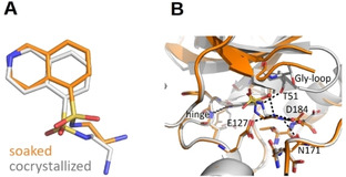
Crystal structures of the short‐chain fasudil derivative 6 in complex with PKA from a soaked (orange, PDB‐code: 6YNB) and a cocrystallized sample (gray, PDB‐code: 5M0B). (A) Ligand superposition indicates a strong rotation of the sulfonamide portion and the attached substituent of the ligand between the two structures (RMSD ligand: 1.2 Å, RMSD of Cα atoms of the hinge region: 0.3 Å). (B) Active site superposition. Dotted lines indicate hydrogen bonds. The position of the Gly‐rich loop is not entirely defined for the crystal structure of the soaked crystal. Strikingly, the positions of those residues visible in the soaked structure (Thr51 and Gly52) differ 2.2–5.0 Å in their backbone position from the cocrystallized structure. Merely, in the latter structure, the Gly‐rich loop is pulled down toward the active site. In both complexes, deviating hydrogen‐bond patterns are formed to different amino acids. In the soaked case, they are established to Val123, Asn171 and Asp184; for the cocrystallized example to Val123, Thr51, and Glu127.
The binding mode of the fragment‐sized ligand 7 (Figure 9) results in nearly identical binding poses for crystals obtained by both crystallization protocols (RMSD ligand: 0.2 Å, RMSD of the Cα atoms of the hinge region: 0.2 Å). As a further example, we crystallized fragment 8 with PKA following both protocols. As in the complex with 7, a perfect match of both structures is found (Figure 10).
Figure 9.
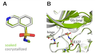
Crystal structures of fasudil‐fragment 7 in complex with PKA from a soaked crystal (green, PDB‐code: 6YNC) and a cocrystallized specimen (gray, PDB‐code: 5M0L). (A) Ligand superposition shows unchanged bound conformation and binding pose in both structures (RMSD ligand: 0.2 Å, RMSD of Cα atoms of the hinge region: 0.2 Å). (B) Active site superposition. Dotted lines indicate hydrogen bonds. The position of the Gly‐loop differs only slightly. The hydrogen‐bonding pattern between ligand and PKA are identical in both structures.
Discussion
In the process of drug design and lead optimization, protein crystallography is an indispensable tool to analyze drug binding to a target protein. [12] The binding mode as well as the actually observed inventory of non‐covalent interactions such as salt bridges, hydrogen bonds and van der Waals interactions are characterized and can be evaluated in terms of distances and angular relationships. Such information is essential to guide the design of subsequent drug candidates for synthesis. There are two commonly applied protocols to produce crystals of protein–ligand complexes for crystallographic analysis, namely cocrystallization and soaking. [13]
For cocrystallization, protein and ligand are mixed in solution prior to crystallization trials and the assembled protein–ligand complex is transferred from solution equilibrium to the crystalline phase.[ 13 , 14 ] Due to the presence of the ligand and the frequent addition of varying amounts of solubilizers, such as DMSO, or other additives, crystallization conditions can differ significantly for a series of cocrystallization trials using different ligands. Sometimes even screenings for completely new conditions are required. Therefore, the development of successful cocrystallization protocols can be quite time‐elaborate and resource‐intensive. [15]
Thus, especially in industry with the typically imposed time restrictions, the much faster soaking method is quite popular. Here, the protein is crystallized in its uncomplexed state without any bound ligand. The pre‐manufactured empty crystals are then exposed in a droplet containing a high concentration of the candidate ligand for which the binding pose is desired to be elucidated. The ligand may diffuse into the crystal and bind to the protein, a process that is usually accomplished in short time. Prerequisite for the success of this procedure is the presence of sufficiently large water‐filled channels passing contiguously through the packed crystal and accessing the protein‐binding site of interest. In case, the soaking remains unsuccessful, one first step should be to validate permeability of the crystal packing channels of the crystal form used for soaking. Nevertheless, in any cases, soaking is the faster method. It requires significantly less material and builds on a well‐established crystallization protocol. [13] Given that the uncomplexed protein crystallizes well, hundreds of differently soaked crystals can be generated from a single crystallization plate opening the perspective to use crystallography for screening purposes. Cocrystallization on the other hand can easily require multiple crystallization plates per ligand in order to find optimal conditions, resulting in a high demand of protein and ligand material. Since screening for novel conditions is required, it cannot be expected that crystallization reveals the same crystal packing. A transformation to another packing mostly in a different space group is probably the rule rather than the exception (s. example below).
Examples for differences between crystal structures obtained from soaked and cocrystallized crystals have been reported.[ 16 , 17 , 18 , 19 , 20 , 21 ] However, the number of systematic and well‐documented examples in literature is still surprisingly small considering its importance for the relevance of the drug‐discovery pipeline. Only human aldose reductase, [14] glutathione S‐transferase of the malarial parasite plasmodium falciparum (PfGST), lymphocyte‐specific kinase (Lyck) and tRNA guanine transglycosylase, a target to fight Shigella infections have been reported in detail.[ 19 , 20 , 21 ]
It has to be noted that in our crystallization experiments the PKI peptide of two different lengths (obtained from two different suppliers) were used to support the crystallization process. In all structures the central part from residue 13 to 22 is well defined and shows minor structural deviations, apart from a peptide flip between position 13 and 14 in some of the complexes. Depending on the studied complex, the number of residues visible in the electron density at the C and N‐terminus of the PKI peptide varies. We believe that the influence of the PKI peptide does not affect the systematic differences between soaking and cocrystallization that we could observe for ligands of different flexibility and molecular weight. These findings are in agreement with another crystallographic study where we modified the PKI peptide significantly but observed only small deviations in the geometry of PKA. [22]
In the PKA case studied here, the overall comparability of soaked and cocrystallized complexes with respect to the obtained binding modes and interaction patterns established between protein and ligands remains limited. As usual practice in drug development projects further detailed design of follow‐up compounds is frequently based on the evaluation of crystal structures. Assuming that the crystal structure has the necessary relevance, would any differences in the optimization strategies result if the design considerations are based on either the soaked or cocrystallized structures? Definitely, alternative strategies will result especially for the ligands 4, 5 and 6. We have to take into account that the present case must even be considered as ideal, since the crystal packing geometry and space group symmetry is preserved for these three ligands between soaking and cocrystallization. PKA, like most kinases, is a flexible protein, especially next to the active site. As we have observed high similarity of the cocrystallized structures presented here, and 2D‐NMR experiments, we can assume that our cocrystallized structures are the better approximation representing the relevant protein–ligand binding pose also in solution.[ 23 , 24 ] It is known that PKA performs conformational adaptations of the Gly‐rich loop upon ligand binding in solution. These adaptations would be missed considering only the soaked crystal structures. Crystallization extends over a long time span and most likely equilibrium conditions are given that can be captured and conserved during cocrystallization. For soaking experiments, this is different as the uncomplexed protein arranges in pre‐manufactured crystals. Hence, the rather constrained environment in the crystal packing allows only minor movements when the ligand diffuses into the crystal with densely packed protein molecules. Required mutual adaptations are spatially restricted and hence, an energetically favorable adaptation is required to drive an entire loop into an altered position upon binding. This cannot take place to the required extend.
The following example underlines this limitation. We recently determined the crystal structures of a congeneric series of trypsin ligands. [25] All experiments were performed by cocrystallization and a conclusive and self‐contained picture of the binding modes resulted. As crystallization of trypsin can be tricky, we also tried soaking. For ligand 9 (Figure 11), we obtained in addition to our previously determined cocrystallized structure, [25] a complex structure from soaking (details about the protocol to obtain the soaked structure, s. SI).
Figure 11.
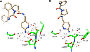
Crystal structures of 9 in the S1 pocket of trypsin (ligand shown in light brown, protein residues in green, heteroatoms color‐coded). Water molecules are shown as red spheres and favorable hydrogen bonds are depicted as black dotted lines with the corresponding distances in Å. (A) Cocrystallized structure in the orthorhombic space group (P212121, PDB‐code: 6T5W). The amino group establishes a hydrogen bond to Asp189 and the pyridine nitrogen interacts with Ser190Oγ. The terminal P3 group adopts two alternative conformation (populated by 51 % for I and 49 % for II), PDB‐code 6T5W. (B) The soaked structure is found in the trigonal space group (P3121, PDB‐code: 6QL0). The amino pyridyl moiety adopts a different orientation and establishes deviating interactions with the protein. The interaction to Asp189 is mediated by a water molecule and the amino group forms an H‐bond to Ser190Oγ.
As immediately obvious from Figure 11, strong deviations in the individual binding poses are observed between the two crystal structures. The amino pyridyl moiety adopts quite different orientations and establishes deviating interactions particularly with Asp189 at the bottom of the specificity pocket. In the soaked structure, the interaction to this residue is mediated by a water molecule and the amino group forms an H‐bond to Ser190Oγ. In the cocrystallized structure the amino group is in direct contact with Asp189. Furthermore, the orientation of the remaining ligand portion takes another path in both crystal structures. Hence, this is another example, where the binding pose of the ligand in the crystal structure derived from soaking does not match the one from cocrystallization. If the binding pose of the ligand's P1 group would be used for subsequent design, quite different consequence would drive further optimization.
Since we studied an entire series of congeneric ligands with trypsin, the deviating geometry found in the soaked structure is clearly an exception. [25] We also studied the same set of ligands against the related serine protease thrombin and observed binding modes corresponding to those of the cocrystallized structures found with trypsin. Interestingly, all thrombin complexes were obtained by soaking. Remarkably, their binding modes match those of the cocrystallized trypsin structures.
Thus, a detailed case‐by‐case analysis is required. To trace the differences in the current trypsin case, we analyzed the local packing of the trypsin molecules in the soaked and cocrystallized complexes (Figure 12).
Figure 12.
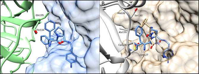
Local packing of trypsin molecules around 9 in the orthorhombic cocrystallized (A) and trigonal soaked (B) complex. (A) One trypsin molecule (solid light‐blue surface) with bound 9 is shown together with an adjacent trypsin molecule in the unit cell (green). The ligand finds sufficient space to even establish the observed split conformation of the P3 portion. (B) Trypsin (solid beige surface) with bound 9 (beige), the adjacent trypsin mate in the packing is shown in gray. The space available for 9 is limited, however, the ligand finds a binding position in the soaking experiment. To indicate the difference in available space, a copy of 9 in the geometry found in the cocrystallized structure has been superimposed (blue sticks).
As obvious from the packing analysis, the trigonal packing of the apo crystals leaves limited space to accommodate the ligand. However, the space is not sufficient to adopt the binding pose consistently found across the entire series. Unfortunately, the adopted pose is not utterly senseless so that in case the soaked complex would be the only one determined of the series, this fact would likely remain undetected.
As the trypsin example demonstrates very clearly, soaked structures bear the risk to suggest misleading binding modes. On the other hand, for the latter example we have seen that the related protease thrombin produces perfectly well relevant geometries by soaking. How about the current PKA case? For ligands 1, 2, and 3 surprisingly, the seven‐membered ring adopts deviating conformations. In one case (1), the observed ring conformers deviate, in a second example (3), they are highly similar. The conformational flexibility of this ring with energetically similar minima is indicated in the cocrystallized complex of 2 where the single structure indicates already two conformers. To complete this puzzling picture, the soaked structure with 2 shows only one conformer, which agrees with the one in the cocrystallized complex and deviates from the second. Ligands 4, 5 and 6 demonstrate that flexible protein regions can remain disordered in a soaked structure and accordingly they are not defined in the electron density. Ligands 5 and 6 indicate that a geometrical adaption of the protein is hampered during ligand binding. In this case soaking influences not only the number of observed interactions, but moreover has an impact on the adopted ligand‐bound conformational rotamer and thus the binding pose. Such a result would be quite misdirecting in a subsequent drug optimization. However, what is the more relevant binding pose in this case? In the current PKA example, we are in the comfortable situation, that also NMR data in solution are available. Remarkably, we have matching results from the corresponding 2D‐NMR experiments; thus we believe our cocrystallization results suggest the more realistic picture of the binding geometry.[ 23 , 24 ]
Similar to our findings, for the kinase Lyck in complex with staurosporine, the soaked crystal structure also underestimated the movement of the Gly‐rich loop. The comparative cocrystallized structure revealed a more prominent movement in this highly flexible protein region. [19]
Ligands 7 and 8 suggest that the impact of the applied crystallization protocol seems to be size‐dependent and influences less the adopted geometry if a small‐sized fragment is studied. Here, we observed virtually identical binding poses. We believe two reasons are important in this context. Firstly, due to their lower affinity, fragments are usually not potent enough to induce larger, energetically costly conformational changes of the protein. Nevertheless, single residue side‐chain flips, required to accommodate a fragment, can still be frequently observed.[ 26 , 27 ] Second, the larger ligands 1–6 exhibit a fair number of torsional degrees of freedom that are rather soft, however, allowing the ligands to adapt to the protein‐packing environment found in pre‐manufactured uncomplexed crystals during the soaking process (cf. trypsin example). Candidates for fragment libraries are usually selected to exhibit a lower number of torsional degrees of freedom. Hence, protein structures and ligand‐binding modes are more likely to show sufficient complementarity in case of the small fragments, thus crystal structures obtained by soaking and cocrystallization show better agreement.
Conclusions
Because of its time and cost effectiveness, soaking is the more popular method to produce crystal structures of protein‐ligand complexes. Here, we demonstrate that the more laborious method of cocrystallization is, however, the superior approach. In particular, for flexible proteins, such as kinases, and for larger ligands supposedly cocrystallization will better capture the correct ligand‐binding pose and induced protein conformations. As we can take reference to NMR data collected in solution on some of the complexes reported in this study, which suggest identical binding poses, we are confident about our conclusion. The geometrical discrepancies of structures obtained from soaked and cocrystallized crystals appear to be smaller for fragment‐sized ligand molecules with a limited number of torsional degrees of freedom. However, for larger and flexible ligands that trigger conformational changes of the protein structure, soaking can be a misleading approach, which, without reference data (e.g. by NMR in solution), is difficult to assess. It likely underestimates the number of possible polar interactions between protein and ligand due to inadequate, highly impaired positions of protein amino‐acid side chain and main chain atoms. If applicable, cocrystallization should be the gold standard to study protein–ligand complexes. It provides the structural insight into equilibrated protein–ligand interactions and adopted complex conformation. These aspects are essential to plan drug optimization in rational terms.
Experimental Section
Protein expression and purification
The catalytic subunit of cAMP‐dependent protein kinase from Chinese hamster ovary cells was expressed with a His‐tag in a modified pET16b‐vector with an introduced TEV‐cleavage site between the protein N‐terminus and His‐tag. This plasmid was transformed into E. coli strain BL21 (DE3)/pLysS (Novagen). [28]
Cell disruption was performed using a high‐pressure homogenizer for multiple cycles. After centrifugation (1 h at 30.000 g) cell lysate supernatant was purified in a first step using a Ni‐NTA column that binds the His‐tag of the protein and was eluted by an imidazole gradient. The His‐tag was then cleaved off by TEV‐protease. Afterwards, an inverse Ni‐NTA column was employed collecting PKA in the flow‐through. Finally, ion exchange chromatography was performed using a MonoS column separating three‐fold phosphorylated PKA from the four‐fold phosphorylated form using a HEPES buffer with sodium chloride gradient. [28]
Crystallization
The cocrystallization protocols of 1, 3–7 were discussed previously.[ 23 , 24 , 29 ] Thus, only differences to the soaking protocols will be reported here. Crystallization for soaking was performed using the hanging drop method at 4 °C. The crystallization drops for 1 and 3–7 contained the following ingredients: 10 mg/mL PKA (240 μM), 30 mM MBT (MES/Bis‐Tris buffer pH 6.2–6.9), 1 mM DTT, 0.1 mM EDTA, 75 mM LiCl, 0.3 mM Mega‐8, 0.7 mM PKI (Sigma Aldrich: P7739 for cocrystals; Sigma Aldrich: SCP0064 for apo crystals for soaking), 120 μM or 1.2 mM ligand dissolved in DMSO from a 50–100 mM stock for cocrystals but not for apo crystals. For 2 and 8 slightly different conditions were applied: 8 mg/mL PKA (200 μM), 100 mM MBT (MES/Bis‐Tris buffer pH 6.9), 1 mM DTT, 0.1 mM EDTA, 75 mM LiCl, 0.2 mM Mega‐8, 0.5 mM PKI (Sigma Aldrich: P7739 for soaked and cocrystals) and 5 mM of 2 or 14 mM of 8 dissolved in DMSO from a 50–100 mM stock for cocrystallization. The well contained a mixture of methanol in water with varying methanol concentrations (v/v) for the different ligands (14‐23 % methanol). In the crystallization setup, streak‐seeding was performed with apo crystals as seeds using a horse hair in order to initialize crystal growth. Soaking was performed for 1 and 3–7 in a buffer containing 30 mM MBT (MES/Bis‐Tris buffer pH 6.9), 1 mM DTT, 0.1 mM EDTA, 75 mM LiCl, 16 % methanol (v/v), 120 μM ligand dissolved with DMSO for 24 hours. For crystal mounting, crystals were cryo‐protected in 5 mM MBT (MES/Bis‐Tris buffer pH 6.9), 1 mM DTT, 0.1 mM LiCl, 120 μM or 1.2 mM ligand dissolved in DMSO from a 50–100 mM stock, 16 % (v/v) methanol, 30 % (v/v) MPD. For 5 mM of 2, a buffer with 30 % (v/v) MPD and 70 % (v/v) of a solution containing 100 mM MBT (MES/Bis‐Tris buffer pH 6.9), 1 mM DTT, 0.1 mM EDTA, 75 mM LiCl, 0.2 mM Mega‐8, 23 % methanol (v/v) was applied. In case of 8, 100 mM were dissolved in the above conditions from a 1 M DMSO stock and soaking of 2 and 8 was performed for 20 minutes. All crystals were flash frozen in liquid nitrogen.
Crystallography
Cocrystal structures of 1 and 3–7 have been documented in previous contributions.[ 23 , 24 , 29 ] The corresponding soaked structures were collected at the storage ring Bessy II Helmholtz‐Zentrum Berlin, Germany at Beamline 14.1 on a Pilatus 6 M pixel detector. The cocrystallized sample of 2 was measured at ESRF ID‐29, Grenoble, France. The datasets were processed using XDS [30] and molecular replacement was performed using CCP4 Phaser [31] and PDB‐structure of PKA from bos taurus 1Q8W as a model. [32] This was followed by simulated annealing, multiple refinement cycles of maximum likelihood energy minimization and B‐factor refinement with Phenix. [33] Coot [34] was used to fit amino‐acid side chains into σ‐weighted 2Fo−Fc and Fo−Fc electron density maps. If appropriate electron density was observed, multiple side chain conformations were built into the model and maintained during the refinement if the minor populated side chain displayed at least 20 % occupancy. Ramachandran plots for structure validation were calculated using PROCHECK. [35] Data collection, unit cell parameters and refinement statistics are given in the SI. Analysis of temperature factors was performed with Moleman. [36] Protein and PKI B‐factors were refined for 1–7 anisotropically, the complex with 8 and water B‐factors were isotropically refined for all soaked structures. Decision for anisotropic or TLS refinement was based on comparison of Rfree. Anisotropic refinement was chosen over TLS if the achieved Rfree values were at least 0.5 % lower for anisotropic than for TLS refinement. Rfree was calculated using 5 % of all reflections, which were randomly chosen and not used for the refinement. The required ligand restraint files were created using the Grade webserver.[ 37 , 38 ] For figure preparation PyMOL and Chimera were used. RMSD calculations were done using the least‐square fit routine developed by MacLachlan and implemented in ProFitV3.3.[ 39 , 40 ] The coordinates from structures received after soaking and cocrystallization were compared with each other for every ligand. For this all Cα‐atoms of the following amino acids were fitted against each other: 15–33, 38–48, 56–119, 124–330, 334–350. Amino acids that have not been fitted are either missing as coordinates or are part of the Gly‐loop, which should not be considered as it could have large deviations. After this fit, RMSD values were calculated for the hinge region (120–123, Cα‐atoms) and the ligands (all atoms) comparing the structures received from cocrystallization with those received from soaking. The Table with all calculated values can be found in the SI as well as the crystallographic tables of the different ligands 1–9.
Accession codes
Ligand ID (soaked/cocrystallized): 1 (6YNA/5LCP), 2 (6YNT/6Y8C), 3 (6YQK/5M6Y), 4 (6YQJ/5LCR), 5 (6YQI/5LCQ), 6 (6YNB/5M0B), 7 (6YNC/5M0L), 8 (6YNR/6Y2O), 9 (6QL0/6T5W)
Supporting Information
The following is supplied as Supporting Information: Crystallographic tables; images of the electron densities of all eight ligands in their soaked and cocrystallized structures, RMSD deviations between soaked and cocrystallized ligands depending on the sets of coordinates used as reference to align the structures, Luzzati plots to estimate coordinate error in atomic positions, applied soaking protocol for ligand 9 against trypsin crystals.
Abbreviations
Ala: alanine, Asp: aspartate, Arg: arginine, BRD1‐4: first bromodomain of bromodomain containing protein 4, DMSO: dimethyl sulfoxide, DTT: dithiothreitol, EDTA: ethylenediaminetetraacetic acid, Glu: glutamate, Gly: glycine, Gly‐loop: glycine‐rich loop, His‐tag: histidine‐tag, Lyck: lymphocyte‐specific kinase, MBT: MES/Bis‐Tris, MPD: 2‐methyl‐2,4‐pentanediol, Ni‐NTA: nickel‐nitrilotriacetic acid, PDB: protein data bank, PfGST: glutathione S‐transferase of the malarial parasite plasmodium falciparum, PKA: cAMP‐dependent protein kinase, RMSD: root‐mean‐square deviation, SBDD: structure‐based drug design, Ser: serine, TEV: tobacco etch virus, Thr: threonine, TLS: translation/libration/screw, Val: valine
Conflict of interest
The authors declare no conflict of interest.
Supporting information
As a service to our authors and readers, this journal provides supporting information supplied by the authors. Such materials are peer reviewed and may be re‐organized for online delivery, but are not copy‐edited or typeset. Technical support issues arising from supporting information (other than missing files) should be addressed to the authors.
Supplementary
Acknowledgements
We acknowledge funding from the European Research Council (ERC) of the European Union, Project Number 268145 (DrugProfilBind). We particularly acknowledge the help and support of the teams during diffraction data collection at BESSY II (HZB, Berlin, Germany) and ESRF, ID29 (ESRF, Grenoble, France). We would like to thank the HZB for a travel grant. Open access funding enabled and organized by Projekt DEAL.
B. Wienen-Schmidt, M. Oebbeke, K. Ngo, A. Heine, G. Klebe, ChemMedChem 2021, 16, 292.
References
- 1. Erlanson D. A., Fesik S. W., Hubbard R. E., Jahnke W., Jhoti H., Nat. Rev. Drug Discovery 2016, 15, 605–619. [DOI] [PubMed] [Google Scholar]
- 2. Chilingaryan Z., Yin Z., Oakley A. J., Int. J. Mol. Sci. 2012, 13, 12857–12879. [DOI] [PMC free article] [PubMed] [Google Scholar]
- 3. Kuhn P., Wilson K., Patch M. G., Stevens R. C., Curr. Opin. Chem. Biol. 2002, 6, 704–710. [DOI] [PubMed] [Google Scholar]
- 4. Scapin G., Curr. Pharm. Des. 2006, 12, 2087–2097. [DOI] [PubMed] [Google Scholar]
- 5. Yin X., Scalia A., Leroy L., Cuttitta C. M., Polizzo G. M., Ericson D. L., Roessler C. G., Campos O., Ma M. Y., Agarwal R., Jackimowicz R., Allaire M., Orville A. M., Sweet R. M., Soares A. S., Acta Crystallogr. Sect. D 2014, 70, 1177–1189. [DOI] [PMC free article] [PubMed] [Google Scholar]
- 6. Schiebel J., Radeva N., Köster H., Metz A., Krotzky T., Kuhnert M., Diederich W. E., Heine A., Neumann L., Atmanene C., Roecklin D., Vivat-Hannah V., Renaud J.-P., Meinecke R., Schlinck N., Sitte A., Popp F., Zeeb M., Klebe G., ACS Chem. Biol. 2016, 11, 1693–1701.27028906 [Google Scholar]
- 7. Taylor S. S., Zhang P., Steichen J. M., Keshwani M. M., Kornev A. P., Biochim. Biophys. Acta 2013, 1834, 1271–1278. [DOI] [PMC free article] [PubMed] [Google Scholar]
- 8. Wong C. F., Biochim. Biophys. Acta 2008, 1784, 244–251. [DOI] [PubMed] [Google Scholar]
- 9. Huang Z., Wong C. F., J. Comput. Chem. 2009, 30, 631–644. [DOI] [PubMed] [Google Scholar]
- 10. Kornev A. P., Taylor S. S., Trends Biochem. Sci. 2015, 40, 628–647. [DOI] [PMC free article] [PubMed] [Google Scholar]
- 11. Taylor S. S., Kornev A. P., Trends Biochem. Sci. 2011, 36, 65–77. [DOI] [PMC free article] [PubMed] [Google Scholar]
- 12. Danley D. E., Acta Crystallogr. Sect. D 2006, 62, 569–575. [DOI] [PubMed] [Google Scholar]
- 13. Hassell A. M., An G., Bledsoe R. K., Bynum J. M., Carter H. L., Deng S.-J. J., Gampe R. T., Grisard T. E., Madauss K. P., Nolte R. T., Rocque W. J., Wang L., Weaver K. L., Williams S. P., Wisely G. B., Xu R., Shewchuk L. M., Acta Crystallogr. Sect. D 2007, 63, 72–79. [DOI] [PMC free article] [PubMed] [Google Scholar]
- 14. Klebe G., Drug Discovery Today 2006, 11, 580–594. [DOI] [PMC free article] [PubMed] [Google Scholar]
- 15. Stewart L., Clark R., Behnke C., Drug Discovery Today 2002, 7, 187–196. [DOI] [PubMed] [Google Scholar]
- 16. Steuber H., Zentgraf M., Gerlach C., Sotriffer C. A., Heine A., Klebe G., J. Mol. Biol. 2006, 363, 174–187. [DOI] [PubMed] [Google Scholar]
- 17. Rauh D., Klebe G., Stubbs M. T., J. Mol. Biol. 2004, 335, 1325–1341. [DOI] [PubMed] [Google Scholar]
- 18. Rauh D., Klebe G., Stürzebecher J., Stubbs M. T., J. Mol. Biol. 2003, 330, 761–770. [DOI] [PubMed] [Google Scholar]
- 19. Zhu X., Kim J. L., Newcomb J. R., Rose P. E., Stover D. R., Toledo L. M., Zhao H., Morgenstern K. A., Structure 1999, 7, 651–661. [DOI] [PubMed] [Google Scholar]
- 20. Hiller N., Fritz-Wolf K., Deponte M., Wende W., Zimmermann H., Becker K., Protein Sci. 2006, 15, 281–289. [DOI] [PMC free article] [PubMed] [Google Scholar]
- 21. Ehrmann F. R., Stojko J., Metz A., Debaene F., Barandun L. J., Heine A., Diederich F., Cianférani S., Reuter K., Klebe G., PLoS One 2017, 12, e0175723. [DOI] [PMC free article] [PubMed] [Google Scholar]
- 22. Müller J., Kirschner R. A., Geyer A., Klebe G., ACS Omega 2019, 4, 775–784. [Google Scholar]
- 23. Wienen-Schmidt B., Jonker H. R. A., Wulsdorf T., Gerber H.-D., Saxena K., Kudlinzki D., Sreeramulu S., Parigi G., Luchinat C., Heine A., Schwalbe H., Klebe G., J. Med. Chem. 2018, 61, 5922–5933. [DOI] [PubMed] [Google Scholar]
- 24. Wienen-Schmidt B., Wulsdorf T., Jonker H. R. A., Saxena K., Kudlinzki D., Linhard V., Sreeramulu S., Heine A., Schwalbe H., Klebe G., ChemMedChem 2018, 13, 1988–1996. [DOI] [PubMed] [Google Scholar]
- 25. Ngo K., Collins-Kautz C., Gerstenecker S., Wagner B., Heine A., Klebe G., J. Med. Chem. 2020, 63, 3274–3289. [DOI] [PubMed] [Google Scholar]
- 26. Radeva N., Schiebel J., Wang X., Krimmer S. G., Fu K., Stieler M., Ehrmann F. R., Metz A., Rickmeyer T., Betz M., Winquist J., Park A. Y., Huschmann F., Weiss M., Müller U., Heine A., Klebe G., J. Med. Chem. 2016, 59, 9743–9759. [DOI] [PubMed] [Google Scholar]
- 27. Radeva N., Krimmer S. G., Stieler M., Schiebel J., Fu K., Wang X., Ehrmann F. R., Metz A., Huschmann F. U., Weiss M., Mueller U., Heine A., Klebe G., J. Med. Chem. 2016, 59, 7561–7575. [DOI] [PubMed] [Google Scholar]
- 28. Kudlinzki D., Linhard V. L., Saxena K., Sreeramulu S., Gande S., Schieborr U., Dreyer M., Schwalbe H., Acta Crystallogr. Sect. F 2015, 71, 1088–1093. [DOI] [PMC free article] [PubMed] [Google Scholar]
- 29. Wienen-Schmidt B., Schmidt D., Gerber H.-D., Heine A., Gohlke H., Klebe G., ACS Chem. Biol. 2019, 14, 2585–2594. [DOI] [PubMed] [Google Scholar]
- 30. Kabsch W., Acta Crystallogr. Sect. D 2010, 66, 125–132. [DOI] [PMC free article] [PubMed] [Google Scholar]
- 31. McCoy A. J., Grosse-Kunstleve R. W., Adams P. D., Winn M. D., Storoni L. C., Read R. J., J. Appl. Crystallogr. 2007, 40, 658–674. [DOI] [PMC free article] [PubMed] [Google Scholar]
- 32. Breitenlechner C., Gassel M., Hidaka H., Kinzel V., Huber R., Engh R. A., Bossemeyer D., Structure 2003, 11, 1595–1607. [DOI] [PubMed] [Google Scholar]
- 33. Adams P. D., Afonine P. V., Bunkóczi G., Chen V. B., Davis I. W., Echols N., Headd J. J., Hung L.-W., Kapral G. J., Grosse-Kunstleve R. W., McCoy A. J., Moriarty N. W., Oeffner R., Read R. J., Richardson D. C., Richardson J. S., Terwilliger T. C., Zwart P. H., Acta Crystallogr. Sect. D 2010, 66, 213–221. [DOI] [PMC free article] [PubMed] [Google Scholar]
- 34. Emsley P., Lohkamp B., Scott W. G., Cowtan K., Acta Crystallogr. Sect. D 2010, 66, 486–501. [DOI] [PMC free article] [PubMed] [Google Scholar]
- 35. Laskowski R. A., MacArthur M. W., Moss D. S., Thornton J. M., J. Appl. Crystallogr. 1993, 26, 283–291. [Google Scholar]
- 36. Kleywegt G. J., Zou J.-Y., Kjeldgaard M., Jones T. A., In International Tables for Crystallography Volume F: Crystallography of biological macromolecules; M. G. Rossmann, E. Arnold, Eds; Springer Netherlands: Dordrecht 2001; 353–356. [Google Scholar]
- 37.O. S. Smart, T. O. Womack, A. Sharff, C. Flensburg, P. Keller, W. Paciorek, C. Vonrhein, G. Bricogne, http://www.globalphasing.com (accessed: June, 19, 2020).
- 38. Bruno I. J., Cole J. C., Kessler M., Luo J., Motherwell W. D. S., Purkis L. H., Smith B. R., Taylor R., Cooper R. I., Harris S. E., Orpen A. G., J. Chem. Inf. Comput. Sci. 2004, 44, 2133–2144. [DOI] [PubMed] [Google Scholar]
- 39. McLachlan A. D., Acta Crystallogr. 1982, A38, 871–873. [Google Scholar]
- 40.A. C. R. Martin, C. T. Porter, http://www.bioinf.org.uk/software/profit/ (accessed June 2020).
Associated Data
This section collects any data citations, data availability statements, or supplementary materials included in this article.
Supplementary Materials
As a service to our authors and readers, this journal provides supporting information supplied by the authors. Such materials are peer reviewed and may be re‐organized for online delivery, but are not copy‐edited or typeset. Technical support issues arising from supporting information (other than missing files) should be addressed to the authors.
Supplementary


