Abstract
Batik wastewater, in general, is colored and has high concentrations of BOD (biological oxygen demand), COD (chemical oxygen demand), and dissolved and suspended solids. Polysulfone (PSf)-based membranes with the addition of polyvinyl pyrrolidone (PVP) were prepared to treat batik industrial wastewater. PSf/PVP membranes were prepared using the phase inversion method with N-methyl-2 pyrrolidone (NMP) as the solvent. Based on the membrane characterization through FESEM, water contact angle, porosity, and mechanical tests showed a phenomenon where the addition of PVP provided thermodynamic and kinetic effects on membrane formation, thereby affecting porosity, thickness, and hydrophilicity of the membranes. The study aims to observe the effect of adding PVP on polysulfone membrane permeability and antifouling performance on a laboratory scale through the ultrafiltration (UF) process. With the addition of PVP, the operational pressure of the polysulfone membrane was reduced compared to that without PVP. Based on the membrane filtration results, the highest removal efficiencies of COD, TDS (total dissolved solid), and conductivity achieved in the study were 80.4, 84.6, and 83.6%, respectively, on the PSf/PVP 0.35 membrane operated at 4 bar. Moreover, the highest color removal efficiency was 85.73% on the PSf/PVP 0.25 operated at 5 bar. The antifouling performance was identified by calculating the value of total, reversible, and irreversible membrane fouling, wherein in this study, the membrane with the best antifouling performance was PSf/PVP 0.25.
Keywords: batik wastewater treatment, blend polymer composite, polysulfone membrane, PVP, antifouling performance
1. Introduction
Batik wastewater is usually obtained from the remaining water from the dyeing and washing process. This wastewater contains chemicals added during the process, such as dyes, starch, oil, wax, lye, and detergents [1]. These substances are generally non-biodegradable, so that they will accumulate in soil and water and cause environmental pollution. Textile industrial wastewaters, in general, are colored and have high levels of biological oxygen demand (BOD), chemical oxygen demand (COD), and dissolved and suspended solids. Dipping wastewater has a characteristic temperature of 29–35 °C, pH ranges from 6.8 to 10.5, COD of 1712.7–1793 mg/L, BOD of 159.7–168 mg/L, and TSS (total suspended solid) of 1233.7–1317 mg/L [2]. Separation technologies that are currently studied by researchers for processing industrial textile wastewater include coagulation/flocculation, ozonation, and membrane technology [3,4,5]. Several researchers have examined the type of membrane technology adequate for processing industrial textile wastewater, including ultrafiltration, nanofiltration, reverse osmosis, membrane distillation, and the use of a membrane bioreactor [6,7,8,9,10]. Ultrafiltration membranes are generally used for separating suspended solids and are particularly suitable for reducing the concentration, purification, and fractionation of macromolecules such as proteins, substances, colors, and other polymeric materials. Dyes for coloring has particles with sizes of 0.5 to 2.0 microns, so they correspond to the pore sizes of the ultrafiltration membrane, which are 0.001–0.05 μm [11].
Membrane filtration processes are often chosen for economic and environmental reasons. However, the membrane has a disadvantage in terms of the limited time that it can be used due to membrane fouling [12,13,14,15]. Nanofiltration and reverse osmosis membranes can remove ions, salinity, and macromolecules in water but are very susceptible to fouling. Therefore, a pre-treatment process is accomplished in the form of ultrafiltration, which can remove impurities that cause fouling on the nanofiltration membrane, and reverse osmosis, which removes suspended solids, colloids, and high molecular mass organic materials [16]. Another combined process was also adopted to minimize this fouling problem in textile wastewater treatment, including combining coagulation and membrane filtration [17,18,19].
Membrane material is an essential factor, considering chemical, thermal, and mechanical stability. Polysulfone is one of the materials commonly used for membrane filtration. Polysulfone has good resistance to alkaline solutions; thus, it is suitable for batik waste [20]. Therefore, membrane preparation is achieved using polysulfone polymers, which have characteristics of excellent stability, wide pH range (pH 2–13), resistance to oxidants, and ease of modification, so that they are often used in the manufacture of membranes [21]. However, polysulfone membranes have low antifouling performance and low membrane flux values due to their low hydrophilic nature [22]. The addition of hydrophilic polymers to the printing solution is often performed to increase membrane permeability and antifouling ability. Commonly used additives include polyvinyl pyrrolidone (PVP) and polyethylene glycol (PEG). Many studies have shown that the addition of PVP between 3 and 90 wt.% of the total doped solution can increase the hydrophilicity, permeability, and antifouling performance of polysulfone membranes [23,24]. The study aims to observe the effect of adding PVP on the permeability and antifouling performance of the PSf membrane on a laboratory scale through the ultrafiltration (UF) process. Before the UF process, the batik wastewater was pretreated through the coagulation and flocculation process using polyaluminum chloride (PAC) coagulants. PAC was chosen as it has many advantages such as fewer aluminum residuals, better performance at low temperature, less sludge volume, less effect on raw water’s pH value, and more rapid flocculation [25].
2. Materials and Methods
2.1. Materials
Polysulfone (PSf, UDEL P-1700 NT11) was provided from Solvay (Brussels, Bel-gium). Polyvinyl pyrrolidone (PVP, MW: 29,000 g/mole), as an additive, was provided from Sigma Aldrich (St. Louis, MI, USA), and N-methyl-2 pyrrolidone (NMP), as a solvent, was purchased from Merck Indonesia. COD reactor digestion vials (Low range, pk/150, method 8000) were provided from HACH, USA. Pt/Co color standard was also purchased from Merck (Darmstadt, Germany).
2.2. Batik Wastewater Pre-Treatment
Batik wastewater pre-treatment was conducted by the coagulation–flocculation method. To carry out this method, 300 mL of batik wastewater was put into a beaker at room temperature, and then the pH of the wastewater was adjusted to pH 4. Polyaluminum chloride (PAC) was added in the amount of 500 ppm of the waste solution and then stirred at 200 rpm for 1 h. The stirring speed was then decreased to 40 rpm for 10 min. The solution was allowed to stand for 30 min for the settling process. The precipitated solution was then filtered with qualitative filter paper to separate out the suspended solids. Resulting pre-treatment batik wastewater samples were analyzed for pH, COD, TSS, color, and TDS concentrations using the methods listed in Table 1.
Table 1.
Analytical methods and equipment used for water quality indicator measurements.
| Indicator | Analysis Method | Equipment |
|---|---|---|
| pH | Electrometric | Water quality meter (AZ 86031) |
| COD | Digestion reaction and UV visible | DRB200 Digital Reactor Block and spectrophotometer UV–Vis (Thermo Fisher Scientific, UV23000) |
| TSS | Standard method 2540D | Glass fiber filter |
| TDS | Electrometric | Water quality meter (AZ 86031) |
| Color | Pt/Co method | Spectrophotometer UV–Vis (Thermo fisher scientific, UV23000) |
| Conductivity | Electrometric | Water quality meter (AZ 86031) |
2.3. Membrane Preparation
Membrane preparation was performed by the phase inversion method [14]. The doped solution was made by slowly adding PVP and polysulfone polymers to the NMP solvent in the ratios listed to Table 2, while stirring at 200 ppm for 30 min. After 30 min, the stirring speed was increased to 300 rpm, and the temperature was raised from room temperature to 60 °C. The temperature was maintained at 60 °C until the solution was homogeneous. After the solution’s viscosity increased, the stirring speed was increased to 500 rpm for 5 h. The doped solution was then allowed to stand at room temperature for 1 h to remove air bubbles that had formed. The doped solution was poured onto a glass plate, flattened with a glass rod to form a thin layer, and then let to stand for 8 min. The liquid layer on the glass plate was soaked in a coagulation bath filled with pure water until a membrane sheet was formed, and then it was allowed to stand in the coagulation bath overnight. The membrane sheet was then immersed in 50% ethanol solution for 1 h and immersed again in 96% ethanol for 30 min. The membrane was then dried at room temperature. An illustration of the preparation process is shown in Figure 1. Ethanol (50%) was used to remove residual organic solvent from the surface and the pores of the membranes. A higher concentration of ethanol (96%) was used at the last stage to ensure that no organic solvent was left on the membrane surface or in the pores and to speed up the drying process of the membrane at room temperature. The membrane preparation was repeated three times for each membrane variant.
Table 2.
Membrane composition.
| Membrane | Composition | ||
|---|---|---|---|
| PSf (g) | PVP (g) | NMP (mL) | |
| Pristine PSf | 7.5 | 0 | 42.5 |
| PSf/PVP 0.15 | 7.35 | 0.15 | 42.5 |
| PSf/PVP 0.25 | 7.25 | 0.25 | 42.5 |
| PSf/PVP 0.35 | 7.15 | 0.35 | 42.5 |
Figure 1.
Illustration of membrane preparation.
2.4. Membrane Characterization
Membrane characterization was performed to identify morphology, functional group changes, hydrophilicity, and membrane porosity. Membrane morphology was investigated by field emission scanning electron micrograph (FESEM, FEI inspect F50). Sample specimens were thinly coated with Au and observed at an excitation voltage of 20 kV. Changes in membrane functional groups were observed with attenuated total reflectance Fourier transform infrared (ATR-FTIR) spectra. The spectra were accomplished using the Nicolet ™ iS50 FTIR Spectrometer with the NIR module and a wavenumber range of 600–4000 cm−1.
Moreover, to observe membrane hydrophilicity, a water contact angle test was performed. This test was accomplished by dripping deionized water on the surface of the membrane. The contact angle was recorded three times randomly and measured with an angle meter. To measure the overall porosity of the membrane, the wet–dry weight method was used. The overall porosity of the membrane was calculated using the following equation [26]:
| (1) |
where Ww is the weight of the wet membranes that were boiled in deionized water for 2 h and then allowed to soak in water for 24 h, Wd is the dry membrane weight, ρw is the density of deionized water, A is the membrane area, and l is the membrane thickness. Two comparable methods measured membrane thickness, i.e., measurement on SEM results and measurement using Dial Thickness (Pressier 307822).
The average membrane pore size was measured using the Guerout–Elford–Ferry formula through the filtration velocity method. The calculation of the membrane pore size average (rm) was obtained by the following equation [27].
| (2) |
where ε is the porosity, η is the viscosity of pure water (8.9 × 10⁻⁴ Pa.s), l is the thickness of the membrane, Q is the volume of permeate per unit time (m3.s−1). A is the effective surface area of the membrane, and ΔP is trans membrane pressure (700 kPa).
The membrane tensile strength was observed in this study to determine the effect of PVP on the mechanical strength of the PSf membrane. The test was carried out using a Universal Tensile Meter (Shimadzu 10 kN) with the standard method of ASTM D882-12. The conditions were performed at room temperature with a 50 mm/min test speed and a distance between the grips of 100 mm. The membrane tensile strength value was calculated by the following equation [28]:
| (3) |
where σ is the tensile strength (MPa), F is the load applied during measurement (N), and A0 is the area of the membrane specimen (m2). The percentage of elongation at break was obtained from the ratio between the initial and extended length at the time of breakage of the tested specimen at room temperature, and was calculated using the following [29]:
| (4) |
where ε is the percentage of elongation at break (%), ΔL is the extended length of the membrane during measurement (mm), and L0 is the length of the original membrane measured according to the distance between the grips (mm).
2.5. Pure Water and Permeate Flux
The membrane performance test was conducted by a cross-flow ultrafiltration system using a pump with variations in feed pressure and time. The membrane, with an effective area of 10.2 cm2, was placed in a membrane cell permeation system, which included a wastewater tank in the feed, a permeate tank, and a retentate tank to accommodate wastewater that did not penetrate the membrane. The operating pressure range of the driving force used was 4–7 bar. The pressure was used for pure water flux, batik wastewater flux (permeate flux), and water flux after backwashing. The pressure was applied except for with the permeate flux on the pristine PSf membrane, where the minimum pressure that could be used to penetrate the membrane was 12 bar. Batik wastewater after pre-treatment was used for membrane performance testing. The permeate flux of the experiment was calculated using the following equation [30]:
| (5) |
where J is the flux in mL.cm−2s−1, V is the volume of the permeate penetrating through the membrane (mL), A is the effective area of the membrane (cm2), and t is time (s).
2.6. Batik Wastewater Removal
The removal efficiency was calculated by the following [31]:
| (6) |
where R is the percent waste removal (COD, TDS, conductivity, and color), Cp is the concentration of substances in the permeate phase, and Cf is the concentration of substances in the feed phase. COD and color were measured by the UV–Vis spectrophotometric method (Thermo fisher scientific, UV23000) using reactor digestion vials (method 8000). Moreover, TDS, conductivity, and pH were measured using a water quality meter (AZ 86031).
2.7. Membrane Fouling Study
The ability of membranes to overcome fouling problems was compared by calculating membrane fouling values. After the wastewater filtration process, the membrane was backwashed with deionized water in 4 bar for 30 min. Membrane fouling was then obtained from the values of pure water flux, which started to become fouled (JW1), permeate flux value (Jp), and flux value after being backwashed (JW2), which were calculated by the following [32]:
| (7) |
| (8) |
| (9) |
where Rr is reversible membrane fouling, Rir is irreversible membrane fouling, and Rt is total membrane fouling.
3. Results and Discussion
3.1. Membrane Characterization
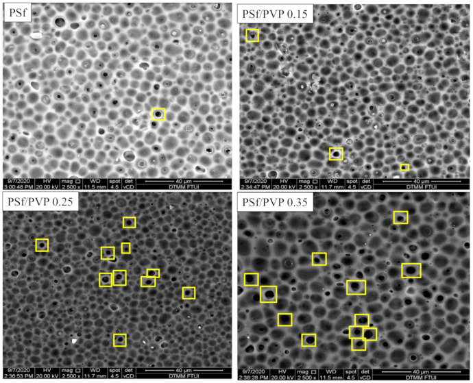
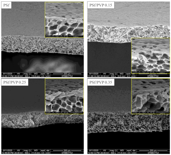
Membrane characterization by FESEM is given in Figure 2 and Figure 3. This study’s preparation resulted in ultrafiltration membrane with an asymmetric structure with non-uniform pores distributed on the top surface and sponge-like macro voids in the sublayer. As shown in Figure 2 and Figure 3, the changes in the membrane after the addition of PVP could be seen in the formation of pores in the image with 2500 times magnification. The addition of 0.25 g PVP to the PSf membrane increased the pore structures in the membrane’s top surfaces [33]. PSf/PVP 0.35 membrane, although it appears to have a larger average pore size compared to pristine PSf (Figure 3 and Table 3), the addition of a larger PVP concentration has an effect of increasing thickness, so that porosity decreases (Table 3) [34].
Figure 2.
FESEM characterization of the surfaces of PSf, PSf/PVP 0.15, PSf/PVP 0.25, and PSf/PVP 0.35 membranes with a magnification of 2500 times.
Figure 3.
FESEM characterization of the cross sections of PSf, PSf/PVP 0.15, PSf/PVP 0.25, and PSf/PVP 0.35 membranes with a magnification of 500 times.
Table 3.
Comparison of the results of measurements of membrane thickness, porosity, average pore size, and water contact angle (WCA).
| Membrane | Membrane Thickness (L, µm) | Porosity (ε, %) | Average Pore Size (rm, nm) | WCA (°) | ||
|---|---|---|---|---|---|---|
| SEM | Dial Thickness | SEM | Dial Thickness | |||
| PSf | 116 ± 9.0 | 158 ± 0.03 | 30.52 ± 2.4 | 24.44 ± 3.1 | 5 | 120 ± 0.5 |
| PSf/PVP 0.15 | 107.5 ± 5.5 | 150 ± 0.01 | 44.77 ± 4.4 | 32.80 ± 2.1 | 17 | 65.37 ± 1.2 |
| PSf/PVP 0.25 | 101 ± 2.0 | 106 ± 0.05 | 71.94 ± 9.8 | 67.88 ± 3.4 | 13 | 50.46 ± 0.8 |
| PSf/PVP 0.35 | 148 ± 5.0 | 226 ± 0.01 | 39.69 ± 1.34 | 26.19 ± 1.3 | 12 | 50.26 ± 3.4 |
The pristine PSf membrane had a high surface tension against organic solvents (41 mN/m) and aromatic groups, making it quicker to settle and tighten the molecules during the coagulation process [35,36]. The addition of PVP to the doped solution has a two-fold effect. Thermodynamically, due to the hydrophilic nature of PVP, it facilitated penetration into the print and sped up solvent and non-solvent exchange. However, kinetically, using PVP can increase the viscosity of the solution [37]. On the PSf/PVP 0.25 membranes, the thermodynamic effect of PVP was more dominant, so that the de-mixing process suddenly occurred; thus, the pores were more formed. In fact, on the PSf/PVP 0.35 membrane, the kinetic effect of high solution viscosity overcame the thermodynamic effect of PVP to inhibit non-solvent diffusion, and a thicker layer membrane was formed. This was confirmed in the analysis of the membrane’s overall porosity, as seen in Table 2, where the PSf/PVP 0.25 membrane had a higher porosity than the PSf/PVP 0.35 membrane. An illustration of the differences in the PSf membrane before and after PVP addition can be seen in Figure 2.
PVP is water-soluble, which must be considered in the formation of pores in the membrane surface. During the membrane coagulation process in deionized water, solvent exchange occurs, so that some of the PVP dissolves in the water and leaves PSf. This phenomenon is predicted to increase the formation of non-uniform pores on the top surface of the PSf/PVP membrane (Figure 2 and Figure 3) [38].
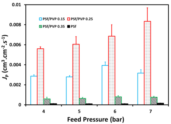
The difference in thickness values obtained from measurement of FESEM images and measurements using dial thickness indicates that the membranes have a non-uniform thickness. However, the change in thickness and porosity values between the two measurements shows the same trend. Based on the results shown in Table 3, the difference in membrane thicknesses of pristine PSf and PSf/PVP 0.15 was not significant. However, the overall porosity and average pores size increased in the PSf/PVP blend membrane compared to the PSf pristine (Table 3). On the PSf/PVP 0.15 membrane, it was seen that the average pore size was reduced compared to the PSf/PVP 0.15 membrane (17 nm to 13 nm), but the porosity and permeability values increased. This is also indicated by an increase in pure water flux on the PSf/PVP 0.25 membrane compared to PSf/PVP 0.15 by three times (from 2.9 × 10⁻³ to 6.1 × 10⁻³ cm3/cm2 s).
The membrane’s hydrophilicity was identified based on the water contact angle (WCA) measurements shown in Table 3. Pristine PSf membranes showed hydrophobic properties with a WCA value greater than 90°. The addition of PVP caused the membrane surface to become more hydrophilic, as indicated by a decrease in the WCA value. The more PVP that was added, the more it showed a tendency to have hydrophilic properties on the membrane surface [39,40,41]. The decrease in WCA from PSf/PVP 0.25 to PSf/PVP 0.35 was very low. WCA values were measured on the membrane surface. In the PSf/PVP 0.35 membrane, where the kinetic effect of PVP was higher and produced a thicker membrane, the PVP distribution was not only on the membrane surface. This caused the WCA value detected on the surface of the PSf/PVP 0.35 membrane to be almost the same as that on the PSf/PVP 0.25 membrane.
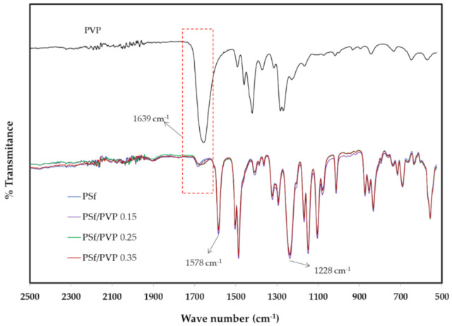
A comparison of the results of ATR-FTIR spectra is presented in Figure 4. The carbonyl bond peak in pure PVP appeared quite clearly at the wave number 1639 cm−1 [24]. This peak also appeared and increased in intensity on the PSf membrane with the addition of PVP (0.25 and 0.35 g) compared to the pristine PSf membrane, although it was not significant. Moreover, the peaks at wave numbers 1578 cm−1 (C=C aromatic vibration) and 1228 cm−1 (C–O–C bonds) were the specific peaks of the PSf membrane [24,42]. The very weak peak of the PSf/PVP membranes in the wavenumber of 1639 cm−1 was due to the low concentration of PVP added to the PSf membrane. There is a possibility that this phenomenon was also due to the nature of PVP, which has a high solubility in water. Thus, some of the PVP was rinsed during the immersion process with water and ethanol. However, considering the results of hydrophilicity characterization (WCA in Table 3) and an increase in membrane flux, this proves that some PVP still existed in the blend membrane, and it was predicted that part of the PVP was capsulated by PSf on the membrane surface [38,43,44].
Figure 4.
Attenuated total reflectance Fourier transform infrared (ATR-FTIR) spectra comparison of the membranes.
Table 4 shows the mechanical strength of the membranes. It can be seen that the addition of PVP reduced the tensile strength of the membrane, as predicted. This occurred due to the increase of pores formed in the membranes with PVP addition [45]. Elastic deformation of the membrane decreased with the addition of PVP; hence, the membrane was more liable to swelling. Moreover, the percentage value of elongation at the break was not the same as the value of tensile strength on the membrane. On the PSf/PVP 0.15 membrane, percent elongation at break increased compared to the pristine PSf membrane, although the tensile strength value decreased. The phenomena appeared due to the increase of the membrane’s plasticity with the addition of PVP at a certain level [24]. A decrease in elongation at break in the PSf/PVP 0.25 membrane and an increase in the PSf/PVP 0.35 membrane identified that the percent of elongation at break could be influenced by the viscosity character of the membrane doped solution [46]. In line with the discussion on FESEM characterization results, the addition of PVP to the PSf/PVP 0.35 membrane had a more dominant kinetic factor than the thermodynamic factor.
Table 4.
The results of mechanical strength test of the membranes.
| Membrane | Tensile Strength (MPa) | Elongation at Break (%) |
|---|---|---|
| PSf | 5.41 ± 0.96 | 33.47 ± 9.75 |
| PSf/PVP 0.15 | 4.63 ± 0.45 | 36.14 ± 12.39 |
| PSf/PVP 0.25 | 4.18 ± 0.45 | 22.90 ± 14.90 |
| PSf/PVP 0.35 | 3.89 ± 0.44 | 27.34 ± 7.34 |
3.2. Batik Wastewater Pre-Treatment
The specific test of the initial Batik wastewater was conducted to obtain an initial reference to measure the effectiveness of the waste treatment process. The characteristics tested were COD, TDS, TSS, conductivity, color, and pH. The treated wastewater was from the leaching process after the coloring process in the batik factory. Before being processed, batik wastewater was filtered first and then diluted one- to fourfold. Dilution is performed as a primary waste treatment to minimize the effects of waste pollution and reduce the concentration when going through the coagulation–flocculation process. If the waste has a high concentration, a hefty dose of coagulant is needed for efficient floc formation [47].
The pre-treatment process was conducted by coagulation–flocculation in the jar test using PAC as a coagulant. PAC is a type of coagulant derived from aluminum salts, often used for textile industrial wastewater treatment as a pre-hydrolyzed coagulant. PAC has advantages such as low alkalinity consumption and produces less sludge than non-hydrolyzed coagulants [48,49]. Wastewater was conditioned based on an optimum pH of 4 and an optimum coagulant dose of 500 ppm [50]. Afterward, the wastewater was filtered with rags. Pre-treatment was performed to remove floc, which could damage the membrane and cause fouling. The pH of the pre-treated waste was changed to pH 7 so as not to damage the membrane. This pH change caused sediment to appear so that the waste was filtered again using filter paper. The filtrate water then became the feed for the membrane filtration process. The characterization of batik waste is presented in Table 5. Pre-treatment successfully reduced COD, TSS, color, and conductivity, but increased TDS. The increase in TDS after pre-treatment was caused by the reduction of pH to pH 4, which caused salt formation due to the addition of acid to the waste, which was initially alkaline [50]. The same phenomena also occurred when setting it to pH 7; salt formation from the neutralization process caused flocs, which increased the TDS, TSS, conductivity, and color.
Table 5.
Comparison of the batik wastewater characteristics.
| Parameter | Unit | Initial Wastewater | After Coagulation–Flocculation | pH 7 Adjustment | After Conventional Filtration |
|---|---|---|---|---|---|
| COD | mg/L | 5100 | 1100 | 1215 | 674 |
| TDS | mg/L | 2200 | 2250 | 2670 | 2590 |
| TSS | mg/L | 700 | 325 | 362 | 3 |
| Conductivity | mS | 4.20 | 4.39 | 5.34 | 5.18 |
| Color | mg/L | 8500 | 378 | 405 | 405 |
| pH | – | 9.40 | 4.09 | 6.99 | 7.00 |
3.3. Pure Water Flux
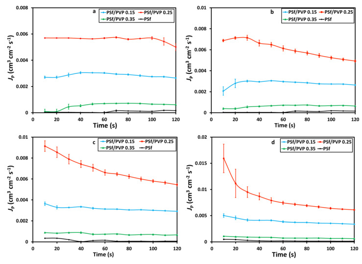
The pure water fluxes conducted at various feed pressure variations of 4, 5, 6, and 7 bar in a cross-flow system characterized the membrane performance test. The pure water flux profiles with time at various membranes and feed pressures are shown in Figure 5 and Figure 6, respectively. The pure water flux profiles in Figure 5 and Figure 6 confirm the membrane’s porosity, where the higher the porosity of the membrane, the higher the value of pure water flux [51,52,53]. The PSf/PVP 0.25 membrane was confirmed to have the highest pure water flux due to the highest porosity. The increase in the feed pressure from 4 to 5 bar had an insignificant effect on the pure water flux. However, after increasing the feed pressure to 6 and 7 bar, the effect was more significant.
Figure 5.
The profile of pure water flux (cm3·cm−2·s−1), JP, with time at the feed pressure of (a) 4 bar, (b) 5 bar, (c) 6 bar, and (d) 7 bar on the membrane filtration process.
Figure 6.
Effect of feed pressure on pure water flux, Jp.
3.4. Batik Wastewater Flux
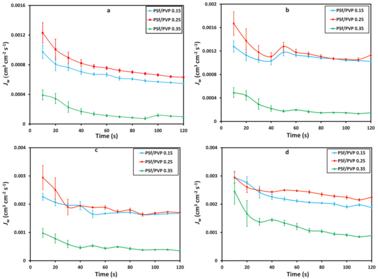
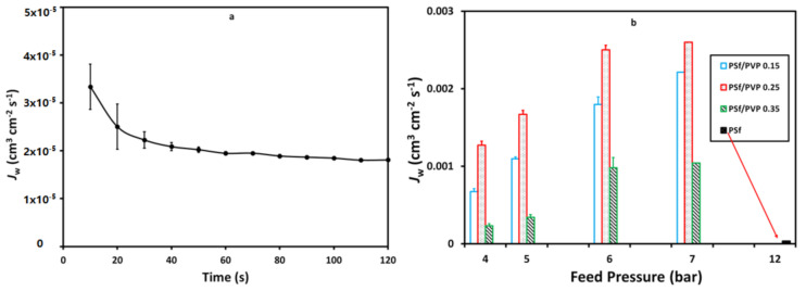
One of this study’s objectives was to see the effectiveness of adding PVP to wastewater treatment applications, especially in the batik industry, at lower operational pressures. This batik wastewater flux study proved that the addition of PVP to polysulfone membranes can be operated at lower pressures than polysulfone membranes without PVP. It could provide preliminary evidence that the application of PSf/PVP membranes for wastewater treatment could provide safe energy [54]. Simultaneously, the PSf/PVP membranes were applied at a pressure of 4–7 bar with a permeate flux range from 9.8 × 10⁻⁵ to 16.7 × 10⁻⁴ cm3·cm−2·s−1. The permeate flux on the PSf/PVP 0.35 membrane was lower, with a significant difference in reduction compared to the PSf/PVP 0.15 and PSf/PVP 0.25 membranes, as presented in Figure 7. Based on the batik wastewater flux profile presented in Figure 8, the pristine PSf membrane cannot operate at pressures below 12 bar with a permeate flux range from 1.8 × 10⁻⁵ to 3.34 × 10⁻⁵ cm3·cm−2·s−1.
Figure 7.
The profile of wastewater flux (cm3·cm−2·s−1), JW, with time at feed pressure of (a) 4 bar, (b) 5 bar, (c) 6 bar, and (d) 7 bar on the membrane filtration process.
Figure 8.
Profile of wastewater flux, JW, of the pristine PSf membrane at 12 bar (a) and the effects of feed pressure on the wastewater flux (b) on the membrane filtration process.
3.5. Pollutant Removal
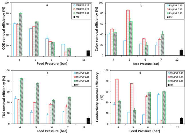
The membrane’s ability to remove pollutants in batik wastewater in various feed pressures is demonstrated in Figure 9. Feed pressure of 4 to 7 bar was applied to PSf/PVP membranes, while feed pressure of 12 bar was applied to pristine PSf membrane. Figure 9 describes the membrane behavior of each waste parameter. In COD and TDS removal, the PSf/PVP 0.35 membrane had the highest removal efficiency. It indicated that the pore size affected the removal process, where it was previously confirmed that the PSf/PVP 0.35 membrane had the lowest porosity compared to other membranes [55]. Moreover, the highest color and conductivity removal efficiency were given by the PSf/PVP 0.25 membrane. The process of removing color and conductivity depends on the charge of the membrane surface [56]. Based on a study by Kajekar et al. (2015), the surface of the PSf/PVP blend polymer composite membrane at a pH above 5 has a negative zeta potential value, and this indicates that there is an electrostatic potential that plays a role when absorbing dyes on the membrane surface [57]. In this case, with a particular composition, the PSf/PVP membrane had a more capable electrostatic contribution, removing the dye and reducing wastewater conductivity.
Figure 9.
The membrane removal efficiency profile of chemical oxygen demand (COD) (a), color (b), total dissolved solid (TDS) (c), and conductivity (d) with feed pressure on the membrane filtration process.
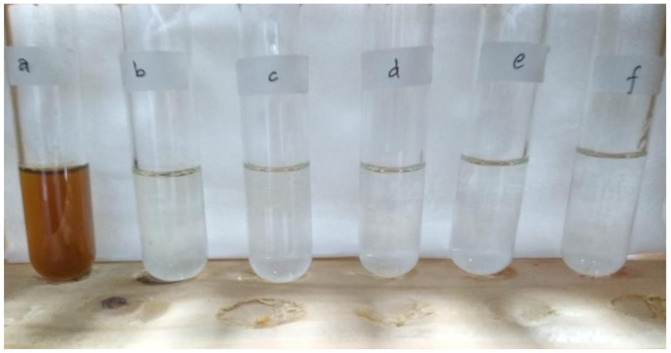
Water samples of fresh batik wastewater after pretreatment and after membrane filtration processes operating at 12 bar for pristine PSf and various PSf/PVP membranes operating at 5 bar are presented in Figure 10. Figure 10 shows the difference in the clarity of fresh wastewater with other water samples. However, it is not easy to distinguish the clarity between water after pretreatment and water permeate after membrane filtration in plain view.
Figure 10.
Water samples taken from (a) fresh batik wastewater and (b) after pretreatment, and permeated feed samples from different membranes: (c) pristine PSf operating at a pressure of 12 bar, (d) PSf/PVP 0.15, (e) PSf/PVP 0.25, (f) PSf/PVP 0.35 operating at 5 bar, respectively.
3.6. Membrane Resistance
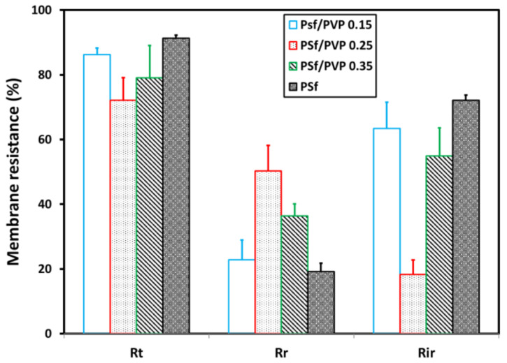
The results of total membrane fouling (Rt), reversible membrane fouling (Rr), and irreversible membrane fouling (Rir) are shown in Figure 11. The high value of total and irreversible membrane fouling indicates low antifouling membrane performance. High reversible membrane fouling identifies that the membrane has a good antifouling performance [32]. Based on the calculation results of membrane fouling in Figure 9, it can be concluded that the PSf/PVP 0.25 membrane had the best antifouling performance. Moreover, the highest irreversible resistance was in the pristine PSf membrane.
Figure 11.
Membrane fouling comparison of various membranes.
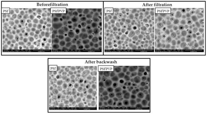
Figure 12 illustrates how the membrane can leave a fouling component that cannot be removed by the backwash process known as irreversible fouling. The greater the potential to leave irreversible fouling, the lower the antifouling performance of the membrane [58]. Moreover, the fouling component that can be removed after the backwash process is reversible fouling. Figure 13 shows the conditions of the pristine PSf and PSf/PVP membranes after the filtration process and after backwash. After the filtration process in the pristine PSf membrane, some pores were seen to be blocked by the fouling component. After the backwash process, a few pores were open, indicating that the reversible fouling was removed. The line marks in the pristine PSf membrane after backwash occurred due to the high pressure applied during the filtration and backwash processes, whereas FESEM of the PSf/PVP membrane (after backwash) showed that the fouling component left on the membrane surface was smaller compared to the pristine PSf. The higher hydrophilicity and lower operating pressure in the cross-flow system minimized the fouling component being forced into the membrane pores, which can cause irreversible fouling [59,60].
Figure 12.
Illustration of membrane fouling and irreversible fouling after filtration and after backwash.
Figure 13.
Comparison of FESEM on the pristine PSf and PSf/PVP blend polymer composite membrane before filtration, after filtration, and after backwash.
4. Conclusions
The experiments were conducted to treat wastewater from the batik industry through a polysulfone-based membrane separation process. This study presents research results proving that the addition of a very low amount of PVP (less than 1 wt.% of the total weight of the doped solution) can still affect the increase in membrane flux and hydrophilicity values. This also affected the decrease in operating pressure required for filtration of batik wastewater after pre-treatment. The results also confirmed that polysulfone-based membranes can be modified by adding PVP by the phase inversion method. The membrane characterization results verified that the addition of PVP has two roles, both from thermodynamic and kinetic aspects. In terms of thermodynamics, PVP increased pore formation and membrane hydrophilicity, although the membrane’s thickness and tensile strength were reduced. Kinetically, it increased the viscosity of the membrane doped solution; hence, the thickness and plasticity of the membrane increased. Both results were shown by FESEM analysis, porosity, water contact angle, and tensile strength test. The solubility of PVP in water is also considered a cause of pore formation in membrane surfaces, and the phenomenon was confirmed by FTIR analysis. The addition of PVP reduced the membrane’s operating pressure by 67%, with COD, color, TDS, and conductivity removal efficiency of 80.4, 85.7, 84.6, and 83.6%, respectively. The antifouling performance was studied, and it was found that the membrane with the highest antifouling performance was PSf/PVP 0.25, with a reversible membrane fouling of 74.04%.
Author Contributions
Conceptualization, S.K.; Data curation, A.F., H., and S.K.; Formal analysis, S.K.; Funding acquisition, S.K.; Investigation, A.H.A., H., A.H.A., and S.K.; Methodology, A.F., A.H.A., and S.K.; Supervision, A.F., M.S., and S.K.; Validation, H., A.H.A., M.S., and S.K.; Writing—original draft, A.H.A. and S.K.; Writing—review and editing, S.K. All authors have read and agreed to the published version of the manuscript.
Funding
This research was funded by PUTI (Project from Universitas Indonesia), grant number NKB-1748/UN2.RST/HKP.05.00/2020.
Institutional Review Board Statement
Not applicable.
Informed Consent Statement
Not applicable.
Data Availability Statement
The data presented in this study are available on request from the corresponding author. The data are not publicy available due to restrictions from the batik industry.
Conflicts of Interest
The authors declare no conflict of interest. The funders had no role in the design of the study; in the collection, analyses, or interpretation of data; in the writing of the manuscript; or in the decision to publish the results.
Footnotes
Publisher’s Note: MDPI stays neutral with regard to jurisdictional claims in published maps and institutional affiliations.
References
- 1.Permadani I., Phasa D.A., Pratiwi A.W., Rahmawati F. The Composite of ZrO2-TiO2 Produced from Local Zircon Sand Used as A Photocatalyst for The Degradation of Methylene Blue in A Single Batik Dye Wastewater. Bull. Chem. React. Eng. Catal. 2016;11:133–139. doi: 10.9767/bcrec.11.2.539.133-139. [DOI] [Google Scholar]
- 2.Khalik W.F., Ong S.-A., Ho L.-N., Wong Y.S., Yusoff N.A., Ridwan F. Decolorization and Mineralization of Batik Wastewater through Solar Photocatalytic Process. Sains Malays. 2015;44:607–612. doi: 10.17576/jsm-2015-4404-16. [DOI] [Google Scholar]
- 3.Yin H., Qiu P., Qian Y., Kong Z., Zheng X., Tang Z., Guo H. Textile Wastewater Treatment for Water Reuse: A Case Study. Process. 2019;7:34. doi: 10.3390/pr7010034. [DOI] [Google Scholar]
- 4.GilPavas E., Dobrosz-Gómez I., Gómez-García M.Á. Coagulation-flocculation sequential with Fenton or Photo-Fenton processes as an alternative for the industrial textile wastewater treatment. J. Environ. Manag. 2017;191:189–197. doi: 10.1016/j.jenvman.2017.01.015. [DOI] [PubMed] [Google Scholar]
- 5.Bilińska L., Blus K., Gmurek M., Ledakowicz S. Coupling of electrocoagulation and ozone treatment for textile wastewater reuse. Chem. Eng. J. 2019;358:992–1001. doi: 10.1016/j.cej.2018.10.093. [DOI] [Google Scholar]
- 6.Ma X., Chen P., Zhou M., Zhong Z., Zhang F., Xing W. Tight ultrafiltration ceramic membrane for separation of dyes and mixed salts (both NaCl/Na2SO4) in textile wastewater treatment. Ind. Eng. Chem. Res. 2017;56:7070–7079. doi: 10.1021/acs.iecr.7b01440. [DOI] [Google Scholar]
- 7.Laqbaqbi M., García-Payo M., Khayet M., El Kharraz J., Chaouch M. Application of direct contact membrane distillation for textile wastewater treatment and fouling study. Sep. Purif. Technol. 2019;209:815–825. doi: 10.1016/j.seppur.2018.09.031. [DOI] [Google Scholar]
- 8.Xu Y.C., Wang Z.X., Cheng X.Q., Xiao Y.C., Shao L. Positively charged nanofiltration membranes via economically mussel-substance-simulated codeposition for textile wastewater treatment. Chem. Eng. J. 2016;303:555–564. doi: 10.1016/j.cej.2016.06.024. [DOI] [Google Scholar]
- 9.Khouni I., Louhichi G., Ghrabi A. Assessing the performances of an aerobic membrane bioreactor for textile wastewater treatment: Influence of dye mass loading rate and biomass concentration. Process. Saf. Environ. Prot. 2020;135:364–382. doi: 10.1016/j.psep.2020.01.011. [DOI] [Google Scholar]
- 10.Cinperi N.C., Ozturk E., Yigit N.O., Kitis M. Treatment of woolen textile wastewater using membrane bioreactor, nanofiltration and reverse osmosis for reuse in production processes. J. Clean. Prod. 2019;223:837–848. doi: 10.1016/j.jclepro.2019.03.166. [DOI] [Google Scholar]
- 11.Lin J., Ye W., Baltaru M.-C., Tang Y.P., Bernstein N.J., Gao P., Balta S., Vlad M., Volodin A., Sotto A., et al. Tight ultrafiltration membranes for enhanced separation of dyes and Na2SO4 during textile wastewater treatment. J. Membr. Sci. 2016;514:217–228. doi: 10.1016/j.memsci.2016.04.057. [DOI] [Google Scholar]
- 12.Yurtsever A., Sahinkaya E., Çınar Ö. Performance and foulant characteristics of an anaerobic membrane bioreactor treating real textile wastewater. J. Water Process Eng. 2020;33:101088. doi: 10.1016/j.jwpe.2019.101088. [DOI] [Google Scholar]
- 13.Tavangar T., Jalali K., Shahmirzadi M.A.A., Karimi M. Toward real textile wastewater treatment: Membrane fouling control and effective fractionation of dyes/inorganic salts using a hybrid electrocoagulation–Nanofiltration process. Sep. Purif. Technol. 2019;216:115–125. doi: 10.1016/j.seppur.2019.01.070. [DOI] [Google Scholar]
- 14.Nyobe D., Ye J., Tang B., Bin L., Huang S., Fu F., Li P., Hu Q. Build-up of a continuous flow precoated dynamic membrane filter to treat diluted textile wastewater and identify its dynamic membrane fouling. J. Environ. Manag. 2019;252:109647. doi: 10.1016/j.jenvman.2019.109647. [DOI] [PubMed] [Google Scholar]
- 15.Erkan H.S., Çağlak A., Soysaloglu A., Takatas B., Engin G.O. Performance evaluation of conventional membrane bioreactor and moving bed membrane bioreactor for synthetic textile wastewater treatment. J. Water Process. Eng. 2020;38:101631. doi: 10.1016/j.jwpe.2020.101631. [DOI] [PMC free article] [PubMed] [Google Scholar]
- 16.Shang W., Tiraferri A., He Q., Li N., Chang H., Liu C., Liu B. Reuse of shale gas flowback and produced water: Effects of coagulation and adsorption on ultrafiltration, reverse osmosis combined process. Sci. Total Environ. 2019;689:47–56. doi: 10.1016/j.scitotenv.2019.06.365. [DOI] [PubMed] [Google Scholar]
- 17.Köse T.E., Biroğul N.Ç. Real textile wastewater reclamation using a combined coagulation/flocculation/membrane filtration system and the evaluation of several natural materials as flocculant aids. Gazi Univ. J. Sci. 2016;29:565–572. [Google Scholar]
- 18.Dos Santos J.D., Veit M.T., Palácio S.M., Da Cunha Gonçalves G., Fagundes-Klen M.R. Evaluation of the combined process of coagulation/flocculation and microfiltration of Cassava Starch wastewater: Removal efficiency and membrane fouling. Water Air Soil Pollut. 2017;228:1–12. doi: 10.1007/s11270-017-3416-3. [DOI] [Google Scholar]
- 19.De Camargo Lima Beluci N., Mateus G.A.P., Miyashiro C.S., Homem N.C., Gomes R.G., Fagundes-Klen M.R., Bergamasco R., Vieira A.M.S. Hybrid treatment of coagulation/flocculation process followed by ultrafiltration in TIO2-modified membranes to improve the removal of reactive black 5 dye. Sci. Total. Environ. 2019;664:222–229. doi: 10.1016/j.scitotenv.2019.01.199. [DOI] [PubMed] [Google Scholar]
- 20.Katheresan V., Kansedo J., Lau S.Y. Efficiency of various recent wastewater dye removal methods: A review. J. Environ. Chem. Eng. 2018;6:4676–4697. doi: 10.1016/j.jece.2018.06.060. [DOI] [Google Scholar]
- 21.Serbanescu O., Voicu S.I., Thakur V.K. Polysulfone functionalized membranes: Properties and challenges. Mater. Today Chem. 2020;17:100302. doi: 10.1016/j.mtchem.2020.100302. [DOI] [Google Scholar]
- 22.Nguyen H.T.V., Ngo T.H.A., Do K.D., Nguyen M.N., Dang N.T.T., Nguyen T.T.H., Vien V., Vu T.A. Preparation and Characterization of a Hydrophilic Polysulfone Membrane Using Graphene Oxide. J. Chem. 2019;2019:1–10. doi: 10.1155/2019/3164373. [DOI] [Google Scholar]
- 23.Moradihamedani P., Abdullah A.H.B. Phosphate removal from water by polysulfone ultrafiltration membrane using PVP as a hydrophilic modifier. Desalination Water Treat. 2016;57:25542–25550. doi: 10.1080/19443994.2016.1150890. [DOI] [Google Scholar]
- 24.Aili D., Kraglund M.R., Tavacoli J., Chatzichristodoulou C., Jensen J.O. Polysulfone-polyvinylpyrrolidone blend membranes as electrolytes in alkaline water electrolysis. J. Membr. Sci. 2020;598:117674. doi: 10.1016/j.memsci.2019.117674. [DOI] [Google Scholar]
- 25.Wei N., Zhang G., Liu D., Wu Y., Wang J., Wang Q. Coagulation behavior of polyaluminum chloride: Effects of pH and coagulant dosage. Chin. J. Chem. Eng. 2015;23:1041–1046. doi: 10.1016/j.cjche.2015.02.003. [DOI] [Google Scholar]
- 26.Vasin S.I., Filippov A. Hydrodynamic Permeability of the Membrane as a System of Rigid Particles Covered with Porous Layer (Cell Model) Colloid J. 2004;66:266–270. doi: 10.1023/B:COLL.0000030834.18269.b3. [DOI] [Google Scholar]
- 27.Kusworo T.D., Ariyanti N., Utomo D.P. Effect of nano-TiO2 loading in polysulfone membranes on the removal of pollutant following natural-rubber wastewater treatment. J. Water Process Eng. 2020;35:101190. doi: 10.1016/j.jwpe.2020.101190. [DOI] [Google Scholar]
- 28.Xu X., Rawat P., Shi Y., Zhu D. Tensile mechanical properties of basalt fiber reinforced polymer tendons at low to intermediate strain rates. Compos. Part B Eng. 2019;177:107442. doi: 10.1016/j.compositesb.2019.107442. [DOI] [Google Scholar]
- 29.Yu M.-F., Lourie O., Dyer M.J., Moloni K., Kelly T.F., Ruoff R.S. Strength and breaking mechanism of multiwalled carbon nanotubes under tensile load. Science. 2000;287:637–640. doi: 10.1126/science.287.5453.637. [DOI] [PubMed] [Google Scholar]
- 30.Doraisammy V., Lai G.S., Kartohardjono S., Lau W.J., Chong K.C., Lai S.O., Hasbullah H., Ismail A.F. Synthesis and characterization of mixed matrix membranes incorporated with hydrous manganese oxide nanoparticles for highly concentrated oily solution treatment. Can. J. Chem. Eng. 2018;96:1612–1619. doi: 10.1002/cjce.23092. [DOI] [Google Scholar]
- 31.Rabiee H., Shahabadi S.M.S., Mokhtare A., Rabiei H., Alvandifar N. Enhancement in permeation and antifouling properties of PVC ultrafiltration membranes with addition of hydrophilic surfactant additives: Tween-20 and Tween-80. J. Environ. Chem. Eng. 2016;4:4050–4061. doi: 10.1016/j.jece.2016.09.015. [DOI] [Google Scholar]
- 32.Karimi A., Khataee A., Vatanpour V., Safarpour M. High-flux PVDF mixed matrix membranes embedded with size-controlled ZIF-8 nanoparticles. Sep. Purif. Technol. 2019;229:115838. doi: 10.1016/j.seppur.2019.115838. [DOI] [Google Scholar]
- 33.Shakak M., Rezaee R., Maleki A., Jafari A., Safari M., Shahmoradi B., Daraei H., Lee S.-M. Synthesis and characterization of nanocomposite ultrafiltration membrane (PSF/PVP/SiO2) and performance evaluation for the removal of amoxicillin from aqueous solutions. Environ. Technol. Innov. 2020;17:100529. doi: 10.1016/j.eti.2019.100529. [DOI] [Google Scholar]
- 34.Matsuyama H., Maki T., Teramoto M., Kobayashi K. Effect of PVP Additive on Porous Polysulfone Membrane Formation by Immersion Precipitation Method. Sep. Sci. Technol. 2003;38:3449–3458. doi: 10.1081/SS-120023408. [DOI] [Google Scholar]
- 35.Zhao C., Liu X., Rikimaru S., Nomizu M., Nishi N. Surface characterization of polysulfone membranes modified by DNA immobilization. J. Membr. Sci. 2003;214:179–189. doi: 10.1016/S0376-7388(02)00524-0. [DOI] [Google Scholar]
- 36.Frank B.P., Belfort G. Atomic Force Microscopy for Low-Adhesion Surfaces: Thermodynamic Criteria, Critical Surface Tension, and Intermolecular Forces. Langmuir. 2001;17:1905–1912. doi: 10.1021/la0011533. [DOI] [Google Scholar]
- 37.Han M.-J., Nam S.-T. Thermodynamic and rheological variation in polysulfone solution by PVP and its effect in the preparation of phase inversion membrane. J. Membr. Sci. 2002;202:55–61. doi: 10.1016/S0376-7388(01)00718-9. [DOI] [Google Scholar]
- 38.Gebru K.A., Das C. Effects of solubility parameter differences among PEG, PVP and CA on the preparation of ultrafiltration membranes: Impacts of solvents and additives on morphology, permeability and fouling performances. Chin. J. Chem. Eng. 2017;25:911–923. doi: 10.1016/j.cjche.2016.11.017. [DOI] [Google Scholar]
- 39.Yuan Z., Dan-Li X. Porous PVDF/TPU blends asymmetric hollow fiber membranes prepared with the use of hydrophilic additive PVP (K30) Desalination. 2008;223:438–447. doi: 10.1016/j.desal.2007.01.184. [DOI] [Google Scholar]
- 40.Qin J.-J., Wong F.-S., Li Y., Liu Y.-T. A high flux ultrafiltration membrane spun from PSU/PVP (K90)/DMF/1,2-propanediol. J. Membr. Sci. 2003;211:139–147. doi: 10.1016/S0376-7388(02)00415-5. [DOI] [Google Scholar]
- 41.Marchese J., Ponce M., Ochoa N., Prádanos P., Palacio L., Hernández A. Fouling behaviour of polyethersulfone UF membranes made with different PVP. J. Membr. Sci. 2003;211:1–11. doi: 10.1016/S0376-7388(02)00260-0. [DOI] [Google Scholar]
- 42.Febriasari A., Purnawan I., Chalid M., Ismojo I., Kartohardjono S. IOP Conference Series: Earth and Environmental Science. IOP Publishing Ltd.; Bristol, UK: 2020. A Direct Comparison Between Poly (vinylidene) Flouride and Polysulfone Flat Sheet Membrane; Characterization and Mechanical Strength; p. 012002. [Google Scholar]
- 43.Tofighy M.A., Mohammadi T., Sadeghi M.H. Highflux PVDF/PVP nanocomposite ultrafiltration membrane incorporated with graphene oxide nanoribbones with improved antifouling properties. J. Appl. Polym. Sci. 2020;138:49718. doi: 10.1002/app.49718. [DOI] [Google Scholar]
- 44.Li M., Wu L., Zhang C., Chen W., Liu C. Hydrophilic and antifouling modification of PVDF membranes by one-step assembly of tannic acid and polyvinylpyrrolidone. Appl. Surf. Sci. 2019;483:967–978. doi: 10.1016/j.apsusc.2019.04.057. [DOI] [Google Scholar]
- 45.Tabatabaei S.H., Carreau P., Ajji A. Microporous membranes obtained from PP/HDPE multilayer films by stretching. J. Membr. Sci. 2009;345:148–159. doi: 10.1016/j.memsci.2009.08.038. [DOI] [Google Scholar]
- 46.Ohya H., Shiki S., Kawakami H. Fabrication study of polysulfone hollowfiber microfiltration membranes: Optimal dope viscosity for nucleation and growth. J. Membr. Sci. 2009;326:293–302. doi: 10.1016/j.memsci.2008.10.001. [DOI] [Google Scholar]
- 47.Rahmadyanti E., Febriyanti C.P. Feasibility of Constructed Wetland Using Coagulation Flocculation Technology in Batik Wastewater Treatment. J. Ecol. Eng. 2020;21:67–77. doi: 10.12911/22998993/123253. [DOI] [Google Scholar]
- 48.Justina M.D., Muniz B.R.B., Bröring M.M., Costa V.J., Skoronski E. Using vegetable tannin and polyaluminium chloride as coagulants for dairy wastewater treatment: A comparative study. J. Water Process Eng. 2018;25:173–181. doi: 10.1016/j.jwpe.2018.08.001. [DOI] [Google Scholar]
- 49.Rana S., Suresh S. Comparison of different Coagulants for Reduction of COD from Textile industry wastewater. Mater. Today Proc. 2017;4:567–574. doi: 10.1016/j.matpr.2017.01.058. [DOI] [Google Scholar]
- 50.Purnawan I., Febriasari A., Setyaputra B., Yolandini T., Windriyo M., Karamah E., Kartohardjono S. IOP Conference Series: Earth and Environmental Science. IOP Publishing Ltd.; Bristol, UK: 2020. Combined Process of Ozonation and Membrane Processes to treat Wastewater from Batik Industry; p. 012003. [Google Scholar]
- 51.An A.K., Guo J., Jeong S., Lee E.-J., Tabatabai S.A.A., Leiknes T. High flux and antifouling properties of negatively charged membrane for dyeing wastewater treatment by membrane distillation. Water Res. 2016;103:362–371. doi: 10.1016/j.watres.2016.07.060. [DOI] [PubMed] [Google Scholar]
- 52.Qtaishat M., Khayet M., Matsuura T. Guidelines for preparation of higher flux hydrophobic/hydrophilic composite membranes for membrane distillation. J. Membr. Sci. 2009;329:193–200. doi: 10.1016/j.memsci.2008.12.041. [DOI] [Google Scholar]
- 53.Chakrabarty B., Ghoshal A., Purkait M. Preparation, characterization and performance studies of polysulfone membranes using PVP as an additive. J. Membr. Sci. 2008;315:36–47. doi: 10.1016/j.memsci.2008.02.027. [DOI] [Google Scholar]
- 54.Sato K., Sugimoto K., Nakane T. Preparation of higher flux NaA zeolite membrane on asymmetric porous support and permeation behavior at higher temperatures up to 145 °C in vapor permeation. J. Membr. Sci. 2008;307:181–195. doi: 10.1016/j.memsci.2007.09.017. [DOI] [Google Scholar]
- 55.Mahat S.B., Omar R., Lee J.L., Mohd Idris A.I., Che Man H., Mustapa Kamal S.M., Idris A. Effect of pore size of monofilament woven filter cloth as supporting material for dynamic membrane filtration on performance using aerobic membrane bioreactor technology. Asia Pac. J. Chem. Eng. 2020;15:e2453. doi: 10.1002/apj.2453. [DOI] [Google Scholar]
- 56.Aouni A., Fersi C., Cuartas-Uribe B., Bes-Pía A., Alcaina-Miranda M., Dhahbi M. Reactive dyes rejection and textile effluent treatment study using ultrafiltration and nanofiltration processes. Desalination. 2012;297:87–96. doi: 10.1016/j.desal.2012.04.022. [DOI] [Google Scholar]
- 57.Kajekar A.J., Dodamani B., Isloor A.M., Zulhairun A.K., Cheer N.B., Ismail A., Shilton S.J. Preparation and characterization of novel PSf/PVP/PANI-nanofiber nanocomposite hollow fiber ultrafiltration membranes and their possible applications for hazardous dye rejection. Desalination. 2015;365:117–125. doi: 10.1016/j.desal.2015.02.028. [DOI] [Google Scholar]
- 58.Huang S., Ras R.H., Tian X. Antifouling membranes for oily wastewater treatment: Interplay between wetting and membrane fouling. Curr. Opin. Colloid Interface Sci. 2018;36:90–109. doi: 10.1016/j.cocis.2018.02.002. [DOI] [Google Scholar]
- 59.Sondhi R., Lin J.Y., Alvarez F. Crossflow filtration of chromium hydroxide suspension by ceramic membranes: Fouling and its minimization by backpulsing. J. Membr. Sci. 2000;174:111–122. doi: 10.1016/S0376-7388(00)00384-7. [DOI] [Google Scholar]
- 60.Wu T.Y., Mohammad A.W., Md. Jahim J., Anuar N. Palm oil mill effluent (POME) treatment and bioresources recovery using ultrafiltration membrane: Effect of pressure on membrane fouling. Biochem. Eng. J. 2007;35:309–317. doi: 10.1016/j.bej.2007.01.029. [DOI] [Google Scholar]
Associated Data
This section collects any data citations, data availability statements, or supplementary materials included in this article.
Data Availability Statement
The data presented in this study are available on request from the corresponding author. The data are not publicy available due to restrictions from the batik industry.


