

Abstract
In donor–acceptor dyads undergoing photoinduced electron transfer (PET), a direction or pathway for electron movement is usually dictated by the redox properties and the separation distance between the donor and acceptor subunits, while the effect of symmetry is less recognized. We have designed and synthesized two isomeric donor–acceptor assemblies in which electronic coupling between donor and acceptor is altered by the orbital symmetry control with the reorganization energy and charge transfer exothermicity being kept unchanged. Analysis of the optical absorption and luminescence spectra, supported by the DFT and TD‐DFT calculations, showed that PET in these assemblies corresponds to the Marcus inverted region (MIR) and has larger rate for isomer with weaker electronic coupling. This surprising observation provides the first experimental evidence for theoretically predicted adiabatic suppression of PET in MIR, which unambiguously controlled solely by symmetry.
Keywords: artificial photosynthesis, chlorin, electron transfer, quinone, symmetry
Two isomeric donor–acceptor assemblies were designed in which electronic coupling is controlled by the orbital symmetry of constituents, while the free energy of photoinduced electron transfer (PET) is constant. This combined experimental/theoretical study surprisingly showed more efficient PET in the isomer with weaker electronic coupling, thus providing a first experimental validation of adiabatic suppression of PET in the Marcus inverted region.

Introduction
Numerous dyads consisting of covalently linked porphyrinoid donors and quinone or fullerene acceptor moieties were investigated as model systems to understand light induced electron transfer of photosynthesis and to design efficient artificial photosynthesis systems.[ 1 , 2 , 3 , 4 , 5 , 6 , 7 , 8 , 9 , 10 , 11 ] The studies showed that the redox properties of the donor and acceptor units and their relative separation and orientation dictate the efficiency of light induced charge separation in these model systems.[ 12 , 13 , 14 , 15 , 16 , 17 , 18 , 19 , 20 ] Less noticeable, but recognizable in some cases, is the effect of symmetry,[ 21 , 22 , 23 , 24 , 25 , 26 , 27 , 28 ] that is the effect of the parity correlation of the donor/acceptor frontier orbitals,[ 21 , 24 , 25 , 26 , 29 , 30 ] as well as appropriate spacer (bridge) orientation.[ 27 , 28 ]
According to the Marcus theory of nonadiabatic electron transfer,[ 31 , 32 , 33 , 34 , 35 ] the rate constant of charge transfer from a donor, D, to an acceptor, A, can be calculated by Equation 1:
| (1) |
where FC is the sum of thermally weighted Franck–Condon factors for nuclear coordinates of the reactants and the surrounding medium. The distance and the orientation dependencies of the rate constant are primarily described in the coupling matrix element, T AD, which is approximately proportional to the overlap integral between the wave functions of the donor, ψD, and the acceptor, ψA [Eq. 2]:[ 32 , 33 , 34 , 35 ]
| (2) |
One can therefore relate the overlap between the donor–acceptor LUMOs as being responsible for the photoinduced electron transfer (PET) when the electron donor is excited.
In this paper, we use two types of chlorin (donor)‐naphthoquinone (acceptor) dyads, shown in Figure 1, to demonstrate the importance of the parity correlation in the donor/acceptor LUMOs to PET. Quite a few examples of dyads with chlorophyll donors have been reported, while the predominant number of investigated dyads make use of porphyrin donors.[ 36 , 37 , 38 , 39 , 40 , 41 , 42 , 43 ] The high symmetry (D 4h) of the porphyrin system A in Figure 1 coins its absorption properties and does not allow for a convenient observation of the symmetry effect on PET (Figure 2).
Figure 1.

Top: LUMOs of chlorin (Chl), 1,4‐naphthoquinone (Q) and 1,4‐dimethoxynaphthalene (MN). LUMOs of ZnChl have similar shape (not shown). Middle and bottom: Chl‐Q isomeric assemblies with norbornadiene bridge Chl‐Q‐C 8 (middle) and Chl‐Q‐D 5 (bottom) and their Zn‐chlorin analogues.
Figure 2.

Symmetry of porphyrin versus chlorin the chromophore of chlorophyll a.
In contrast to porphyrin (Figure 2 A), chlorin type chromophores (Figure 2 C), present in naturally occurring chlorophylls of plant photosynthesis show a lower C 2h symmetry (Figure 2 B). The reduced symmetry of chlorin gives rise to different light absorbance most noticeable by the green color of chlorophylls compared to the red of porphyrins for example, red blood pigment heme. The different absorption properties of both systems, porphyrin and chlorin, can be interpreted in terms of MO theory.[ 44 , 45 , 46 , 47 ] While porphyrin has degenerate LUMO orbitals of e g symmetry, [48] the chlorin molecule has the degeneracy of LUMO lifted due to the aliphatic saturation of one pyrrole ring (Figure 1). The saturated pyrrole lacks the two π electrons necessary for exciting a corresponding eg MO (say e gx), thus raising its energy and leaving a transition to another MO, e gy, almost exclusively responsible for the lowest energy excited state. Such induced geometrical disproportion can be used for funneling electron transfer along one preferential direction, which would be different in the two isomers that have the same acceptor molecule attached to different pyrrole rings. Due to the reduced symmetry in the case of chlorin, its effect on PET should become observable. In order to investigate this influence of symmetry we designed and synthesized appropriate chlorin naphthoquinone dyads 5 and 8 of different symmetry. Naphthoquinone has the parity of its LUMO appropriate for the maximum overlap with the LUMO of chlorin when linked to the pyrrole D (i.e. Chl‐Q‐D 5, Figure 1), and minimum overlap when linked to the pyrrole C. Therefore, Chl‐Q‐D (5) is expected to have an improved coupling as compared with Chl‐Q‐C (8). Marcus theory [Eq. (1)] suggests that the two isomers, like in our case, with “identical” energies of the involved states but different TAD should have the rates of charge transfer differ proportional to TAD 2. Our system offers a good opportunity to test such prediction.
Accordingly, this work focuses on synthesis and photochemical studies of donor–acceptor assemblies Chl‐Q‐D (5) and Chl‐Q‐C (8). Opposite to a simplistic prediction, we found that PET transfer was dampened in the isomer with higher electronic coupling between donor and acceptor. This counterintuitive observation was connected to the realization that PET between Chl‐Q‐D and Chl‐Q‐C corresponds to the Marcus inverted region. Interestingly, several earlier theoretical works predicted such an effect of adiabatic suppression of PET arising due to the increased electronic coupling. To our knowledge, this report is the first experimental evidence to the nontrivial phenomenon of adiabatic suppression of PET. The details of this combined synthetic, spectroscopic, and computational work are described below.
Results and Discussion
For construction of chlorin target structures Chl‐Q‐D (5) and Chl‐Q‐C (8) a general synthesis concept from the Bremen laboratory successfully applied for syntheses of several porphyrinoid and corrinoid macrotetracycles was applied here.[ 49 , 50 , 51 , 52 , 53 , 54 , 55 , 56 ] The concept employs different monocyclic building blocks for each of the target chlorins 5 and 8 of different symmetry (Figure 3).
Figure 3.

General synthesis concepts for construction of naphthoquinone chlorin dyads 5 and 8 of different symmetry.
Pyrrolic building blocks 1–4 should be assembled together to form macrotetracycle 5. Constitutionally isomeric chlorin 8 should be obtained from pyrrole precursors 1, 2, 6 and 7 (Figure 3). Both target chlorins 5 and 8 exhibit C1 symmetry due to methyl substituents at saturated pyrrole rings A. But considering only the chromophores including naphthoquinone moieties the envisaged different (pseudo)symmetries of Cs for 5 and C 2h for 8 can be recognized. Key building blocks for divergent constructions of isomeric chlorins 5 and 8 are pyrroles 3 and 7 bearing required naphthoquinone moieties and appropriate functionalities in α‐positions. These functionalities allow linkage with adjacent ring units. Starting point for preparation of the different C and D pyrroles for chlorins 5 and 8 is pyrrole 9 which was achieved according a general synthetic procedure previously developed.[ 57 , 58 ] Vilsmeier formylation of 9 directly afforded aldehyde 10 as ring C building block for chlorin 8. Subsequent hydrolysis of ethyl ester in 10 followed by iodination of intermediate carboxylic acid 11 yielded pyrrole ring D precursor for chlorin 5 (Scheme 1). Hydronaphthoquinone dimethyl ether moiety of starting pyrrole 9 instead of the final quinone structure is a consequence of requirements in the course of preparation of pyrrole 9. [58] The hydronaphthoquinone ether moieties can be transformed in later stages of chlorin syntheses into required quinone parts.
Scheme 1.

(a) POCl3, DMF, ClCH2CH2Cl, 5 °C to reflux, 2 h, then NaOAc, reflux, 15 min (71 %). (b) LiOH, H2O, THF, 102 °C, 1.5 h (100 %). (c) (i) NaHCO3, H2O, 15 min, 73 °C; (ii) I2, KI, H2O, ultrasonic bath, 73 °C, 45 min (72.2 %).
Synthesis of naphthoquinone chlorin 8
Base‐induced condensation of ring B pyrrolinone 2 and ring C aldehyde 10 yielded BC dipyrromethenone intermediate 13 in almost quantitative yield (Scheme 2). Very strong Schwesinger's base (BEMP) and azeotropic removal of water with benzene as solvent is crucial for success of the reaction. [52] Dipyrromethenone 13 was transformed into its thiolactam derivative 14 for preparing its linkage with ring A building block 15 by sulfide contraction.[ 50 , 51 , 53 , 59 , 60 , 61 ] The reaction sequence is initiated by bromination of enaminoide double bond of 15 and proceeded with high yield. Nucleophilic substitution of bromide of 15‐Br via its imino tautomer by thiolactam 14 formed a sulfur linked tricyclic thioiminoester. The thioiminoester underwent the actual intramolecular C−C bond formation by sulfide contraction with trifluoroacetic acid in the presence of thiophilic tris‐cyanoethylphosphine in benzene. Ester cleavage and decarboxylation initiated sulfide contraction whereby benzene as solvent was crucial for success of the process as investigated and discussed in earlier studies. [53]
Scheme 2.
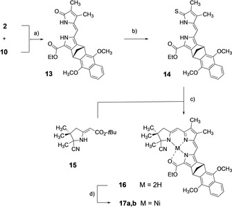
(a) 2‐tertButylimino‐2‐diethylamino‐1.3‐dimethyl‐1.3‐diaza‐2λ3‐phosphacyclohexane (BEMP), benzene, reflux, 14 h (93.7 %). (b) P4S10, NaHCO3, THF, Ar, room temp., 50 min, then add. of 13, reflux, 3 h (78.3 %). (c) (i) 15, NBS, CH2Cl2, room temp., 20 min; (ii) 15‐Br, +14, DBU, MeCN, room temp., Ar, 40 min, alox chromatography; (iii) TFA, benzene, P(CH2CH2CN)3, alox chromatography. (d) Ni(OAc)2×4 H2O, NaOAc, CH2Cl2, MeOH, Ar, room temp., 20 min (71.3 % rel 14).
Because electron rich ABC tricycle 16 is quite sensitive to oxygen and light it was stabilized by complexation with nickel(II). Crystalline nickel complex 17 a,b proved to be very stable and occurred as binary mixture of diastereomers 17 a and 17 b due to chiral centers in position 20 of ring A and nor‐bornane structure at ring C. For analytical purposes diastereomers were separated by HPLC [Polygosil 60‐10, CH2Cl2/n‐hexane (85:15)] and each single diastereomer was crystallized for X‐ray structure investigations. These studies will be discussed later.
After hydrolysis of the ethylester function of 17 a,b the crude carboxylic acid undergoes direct acid induced condensation with decarboxylation and decomplexation with iodopyrrole aldehyde 6 to form tetrapyrrole 18 (Scheme 3). Crude metal‐free tetracycle 18 was re‐complexed with zinc(II) diacetate in situ under cyclization conditions. Heating of 18 with DBU in carefully degassed sulfolane afforded zinc chlorin 19. Zinc exercises a template effect for cyclization which is initiated by HCN elimination from ring A.
Scheme 3.

(a) (i) 17 a,b, KOH (5 N), MeOH/H2O, (9:1), THF, reflux, 45 min; (ii)+6 (2.5 equiv), CHCl3, p‐TsOH, (0.4 N), reflux, Ar, 1 h; (iii) Zn(OAc)2, DBU, sulfolane (degassed), 80 °C, 2 h (22.3 % rel. 17 a,b). (c) (i) BBr3 (1 N in CH2Cl2), CH2Cl2, −78 °C to room temp., Ar, 12 h; (ii)+saturated NaHCO3, H2O, room temp., 1 h (32 %). (d) Zn(OAc)2, NaOAc, MeOH, room temp., Ar, 20 min.
Enamine, formed by this elimination, undergoes nucleophilic attack at iodinated position of ring D to chlorin 19 via ring closure. Dimethylether of naphthoquinone moiety of chlorin 19 was cleaved under standard reaction conditions with BBr3 at low temperature. The acidic reaction conditions also removed the central zinc(II) and oxygen from air lead to formation of the desired naphthoquinone moiety of target chlorin 8. A small sample of 8 a for UV/Vis measurements was prepared according the procedure described for 5 a (Scheme 4).
Scheme 4.

(a) (i) KOH (5 N), MeOH/H2O (9:1), THF, reflux, 45 min; (ii)+12, CHCl3, p‐TsOH (0.4 N), reflux, Ar, 40 min (79 %). (b) Zn(OAc)2, DBU, sulfolane (degassed), 80 °C, 2 h (36.2 % rel. 20). (c) (i) BBr3 (1 N in CH2Cl2), CH2Cl2, −78 °C to room temp., Ar, 12 h; (ii)+H2O, room temp., 1 h (67.6 %). (d) Zn(OAc)2, NaOAc, MeOH, room temp., Ar, 20 min (71 %).
Synthesis of naphthoquinone chlorin 5
Nickel tripyrrin 20 was applied for syntheses of several different chlorins and hexadehydro corrins is starting point for preparation of chlorin 5 here.[ 49 , 50 , 53 ] Tricyclic nickel complex 20 was linked with iodopyrrole aldehyde 12 (Scheme 4). Smooth hydrolysis of 20 to the free carboxylic acid and subsequent condensation with aldehyde 12 under decarboxylation yielded tetrapyrrole 21.
Transformation of tetrapyrrole 21 into chlorin 22 was performed as for 19 in the presence of zinc(II) and DBU in sulfolane. Synthesis of target chlorin 5 was completed by cleavage of the naphthohydroquinone dimethylether with BBr3 as described for isomeric chlorin 8. Zinc(II) was also removed from the macrotetracycle under the acidic reaction conditions. To obtain zinc chlorin 5 a re‐complexation with zinc(II)diacetate was performed.
X‐ray structures of nickel(II)tripyrrin complexes 17 a and 17 b
Structural parameters gained from X‐ray analysis revealed 1RS,8SR,20SR configuration for 17 a which was eluted first by HPLC (tR=13.8 min). Less mobile HPLC fraction (tR=17 min) 17 b exhibits 1RS,8SR,20RS configuration (Figure 4).
Figure 4.

X‐ray crystal‐structure analysis of diastereomeric {ethyl‐[(20‐cyano‐1,8,18,19,20,23‐hexahydro‐1,8‐methano‐2,7‐dimethoxy‐13,14,19,19,20‐pentamethyl‐21H‐anthraceno[b]tripyrrin)carboxylato]}nickel(II) (17 a and 17 b; C38H38N4O4Ni, M 673,43, thermal ellipsoids showing at 50 % level, 17 a solvent omitted for clarity). 17 a: Triclinic, space group P‐1‐, ρ cald=1.328 Mg m−3, Z=2, a=1104.8 (3), b=1158.4(3), c=1458.2 (3) pm, α=84.38(2), β=81.26(2), γ=76.82(2)o, V=1.7921(8) nm3, μ(MoKα)=0.589 mm−1, wR2=0.1392. 17 b: Orthorhombic, space group Pbca, ρ cald=1.363 Mg m−3, Z=8, a=1731.5 (7), b=1936.9(5), c=1956.5 (6) pm, α=90(2), β=90(2), γ=90(2)o, V=6.562(4) nm3, μ(MoKα)=0.639 mm−1, wR2=0.1117.
Noteworthy for both diastereomers is the fact that carbonyl double bonds of ester functions exhibit remarkable long bond lengths of 127 pm. Based on CSD data retrieval including 2262 references for bond lengths of carbonyl groups of ethyl ester functions, an average bond length of 120.2 pm was reported, [62] while a retrieval for ethyl ester carbonyl fragments complexed by nickel(II) (15 references) indicated an average bond length of 122.6 pm. The maximum bond length among these references was reported as 125.4 pm. Stretching of the ester carbonyl bond of 17 a and 17 b by complexation with nickel(II) should facilitate ester hydrolysis. Indeed, this is an advantage for the next synthesis step with 17 a,b.[ 50 , 51 , 52 , 53 ] In both nickel complexes 17 a and 17 b coordinative Ni−N bonds have normal bond lengths between 182.5 and 187.2 pm, whereas Ni−O bonds are considerably longer, 193.4 pm. Planarity of all bonds directly involved in coordination around central nickel(II) is almost perfect. Average deviations from planarity of 7 pm for 17 a and 1 pm for 17 b are negligible.
Spectroscopic characterization
The absorption spectra in Figure 5 A show that the Q‐band (≈600–670 nm) for the Chl‐Q‐D dyad (5) is much broader than those of chlorin itself and another isomer, Chl‐Q‐C (8). The effect persists with the Zn form of chlorins, as shown in Figure 5 B. The increased width of the Q‐band in ZnChl‐Q‐D (5 a) and Chl‐Q‐D (5) dyads is due to the expected substantial charge transfer character in those transitions. The assignment is supported by the lack of such broadening in ZnChl‐dimethoxynaphthalene‐D (ZnChl‐MN‐D, 22), see Figure 5 B, in which electron‐transfer character of the transition is suppressed owing to the electron‐donating character of MN and mismatching parity of the chlorin/MN LUMOs (Figure 1).
Figure 5.

Absorption spectra of chlorin‐based dyads in toluene: A) with free base chlorin, B) with Zn chlorin. Solid blue line denotes the spectra of Chl (A) and ZnChl (B), dashed red line‐spectra of Chl‐Q‐D 5 (A) and ZnChl‐Q‐D 5 a (B), dashed black line‐spectra of Chl‐Q‐C 8 (A) and ZnChl‐Q‐C 8 a (B), and dashed green line‐spectrum of ZnChl‐MN‐D 15.
Figure 6 shows that quinones in both isomers, C and D, do quench fluorescence of chlorin by means of charge transfer. Careful inspection of Figure 6 reveals that the residual fluorescence of the dyads has different spectra compared to those of chlorins, thus rejecting a possibility of trace amount of chlorins being responsible for the fluorescence. Since there is no charge transfer between MN and chlorin in ZnChl‐D‐MN (22), fluorescence of chlorin is not quenched in this dyad. Notably, fluorescence is quenched more efficiently for C isomers than for D isomers in both ZnChl‐Q‐C/ZnChl‐Q‐D (8 a/5 a) and Chl‐Q‐C/Chl‐Q‐D (8/5) pairs.
Figure 6.

Normalized fluorescence spectra of the same dyads as in Figure 5.
Theoretical modeling
It may seem surprising that fluorescence is quenched more efficiently in C than in D isomers of chlorin‐quinone dyads despite the improved overlap and electronic coupling in D isomers and thus expected increase of the charge‐transfer rate as per Equation (1). In the following discussion, we use DFT and TD‐DFT calculations to propose an explanation for this discrepancy. These calculations were undertaken at the B1LYP‐40/6‐31G(d)+PCM(toluene) level of theory, in which the standard BLYP functional was complemented by the 40 % admixture of the exact exchange (i.e. Hartree–Fock) term to allow for the accurate description of the electronic structure of ion‐radical and excited states.[ 63 , 64 , 65 , 66 , 67 ] Furthermore, we established that the 40 % fraction of the Hartree–Fock term maximizes agreement with the experimental absorption spectra of the dyads presented in Figure 1, see Figure S2 in the Supporting Information.
The TD‐DFT calculations, based on the ground state equilibrium geometries obtained using DFT approach,[ 41 , 68 ] revealed that the excited state S1 in both C and D isomers had mostly the charge‐transfer (CT) character (D+A−) as evidenced by the large values of their dipole moments, μ(S1)=29.6 and 25.9 D, respectively (Figure 7). The excited state S2 had mostly the local excitation (LE) character (D*A) with μ(S2)=4.0 and 3.4 D for C and D isomers, respectively (Figure 7). For comparison, the ground state dipole moments are μ(S0)=3.5 and 2.6 D for Chl‐Q‐C (8) and Chl‐Q‐D (5), respectively. The dyads with Zn have similar values.
Figure 7.

Calculated wavelengths, oscillator strengths, and associated differences in the dipole moments Δμ=μ(Si)−μ(S0) (Δμ shown using false color legend shown on the right side of the Figure) for the transitions from the ground to low‐lying electronic states of Chl‐Q‐C (8) and Chl‐Q‐D (5) [B1LYP‐40/6‐31G(d) +PCM(toluene).[ 63 , 64 , 65 , 66 , 67 ]
The electronic coupling between the CT and LE diabatic states, roughly estimated using the DFT calculations, was expectedly found to be larger in Chl‐Q‐D 5 (940 cm−1), see Figure S2 in the Supporting Information) than in Chl‐Q‐C isomer 8 (150 cm−1), in agreement with the qualitative analysis based on the LUMO orbital symmetries. Note that these large values are due to nonplanarity of norbornadiene bridge. Greater electronic coupling for the D isomers leads to the mixing of the CT and LE states and consequent increase of the oscillator strengths and decrease of the dipole moments in the S1 states of D isomers, as compared with C isomers, see Figure 7 and Tables S14–S17 in the Supporting Information. These findings from TD‐DFT calculations are consistent with the experimental absorption spectra of the dyads, in which the CT feature is more pronounced in the case of Chl‐Q‐D 5 and ZnChl‐Q‐D 5 a (Figure 5). Similar trends were obtained using much simpler semi‐empirical AM1 and CIS‐AM1 calculations, and this observation supports usefulness of semi‐empirical methods for quick exploratory calculations.
These experimental and computational results show that the CT state has lower energy than the LE state at the ground‐state equilibrium geometry [69] thus indicating that PET in the dyads from Figure 1 corresponds to the Marcus inverted region (MIR). This result is further validated by the TD‐DFT calculations used to find the equilibrium geometries for the first excited states. By assuming a quadratic form of the diabatic CT and LE states along the charge transfer reaction coordinate, we constructed the free energy profile of PET (Figure 8 A) and fitted the ΔG and λ values to be of ≈0.55 eV and ≈0.31 eV, respectively (see Figure S4 in the Supporting Information). The large positive difference between the free energy ΔG and reorganization energy λ further supports the conjecture of the MIR regime for the PET in chlorin‐quinone dyads.
Figure 8.

A,B) Schematic PET diagram for C and D isomers, respectively. Green arrows in panel A and yellow arrow in panel B highlight the adiabatic suppression of PET in Chl‐Q‐D (5). C) Schematic depiction of dependence of PET rate of electronic coupling in MIR.
The computational results presented above were obtained using the polarized continuum model with the parameters characteristic for toluene. The experimental results were also primarily obtained in toluene. As we see in Table S6 in the Supporting Information, in more polar solvent, that is, dichloromethane, the quantum yield of fluorescence is significantly dropped compared to toluene.
In the light of the finding that PET in chlorin‐quinone dyads occurs in MIR, the observation of the reduced PET rate with increasing coupling is not surprising as it was theoretically predicted more than two decades ago.[ 70 , 71 ] In 1994, Stuchebrukhov and Song [70] applied the centroid coordinate method to the problem of electron transfer in MIR and demonstrated that the electron transfer rate must pass through the maximum and decrease exponentially with the increase of electronic coupling causing the splitting between the adiabatic levels to increase, as illustrated in Figure 8 B. In 1996, Georgievskii et al. [71] applied Langevin equation to the same problem and arrived at the similar conclusion to dub the predicted effect as “adiabatic suppression”. Later theoretical works[ 72 , 73 ] also reproduced the effect of adiabatic suppression.
Despite the multiple theoretical predictions of the electron transfer suppression in the inverted region, to the best of our knowledge, there has been no experimental evidence for this effect in single‐molecule donor‐acceptor or donor‐bridge‐acceptor assemblies. [74] Accordingly, the current study of PET in chlorin‐naphthoquinone dyads demonstrates for the first time an example of two assemblies with identical donor, acceptor, and bridge components, in which increased coupling leads to the decreased rate of PET due to the adiabatic suppression in MIR, as schematically depicted in Figure 8 C.
Conclusions
We have designed two simple donor‐bridge‐acceptor assemblies in which electronic coupling between donor and acceptor was varied by the orbital symmetry control while the charge transfer reorganization energy and exothermicity were kept constant. The photoinduced electron transfer in (Zn)Chl‐Q dyads was shown to correspond to the inverted region of Marcus model, in which greater coupling led to the adiabatic suppression, that is, lower rate of charge transfer, due to the increased energy gap between the charge‐transfer and locally excited states. Awareness of the fact that improved electronic coupling might lead to worse performance of the donor‐acceptor or donor‐bridge‐acceptor assemblies is important for the design of molecules for photovoltaic applications as it indicates that electronic coupling must be fine‐tuned rather than maximized in the donor‐bridge‐acceptor assemblies with large exothermicity of the charge transfer.
Experimental Section
Crystallographic data
Deposition numbers 2006646 and 2006647 (17 a and 17 b) contain the supplementary crystallographic data for this paper. These data are provided free of charge by the joint Cambridge Crystallographic Data Centre and Fachinformationszentrum Karlsruhe Access Structures service www.ccdc.cam.ac.uk/structures.
Conflict of interest
The authors declare no conflict of interest.
Supporting information
As a service to our authors and readers, this journal provides supporting information supplied by the authors. Such materials are peer reviewed and may be re‐organized for online delivery, but are not copy‐edited or typeset. Technical support issues arising from supporting information (other than missing files) should be addressed to the authors.
Supplementary
Acknowledgements
We thank Dr. P. Schulze, Mrs. I. Erxleben, Dipl.‐Ing. J. Stelten (Institute of Organic and Analytical Chemistry, Laboratory Prof. Dr. D. Leibfritz, University of Bremen) for Mass spectrometry and NMR spectroscopy measurements, Dr. H.‐M. Schiebel (TU Braunschweig) for interpretation of mass spectra and Dr. V. Azov for supporting manuscript preparation. We are indebted to Mrs. A. Lincke for performing analytical and preparative HPLC separations. This work was supported by Deutsche Forschungsgemeinschaft Mo 274/10 and the Extreme Science and Engineering Discovery Environment (XSEDE) TG‐CHE170004. Open access funding enabled and organized by Projekt DEAL.
Y. Abel, I. Vlassiouk, E. Lork, S. Smirnov, M. R. Talipov, F.-P. Montforts, Chem. Eur. J. 2020, 26, 17120.
Dedicated to Professor Albert Eschenmoser on occasion of his 95th birthday
Contributor Information
Prof. Dr. Sergei Smirnov, Email: snsm@nmsu.edu.
Prof. Dr. Marat R. Talipov, Email: talipovm@nmsu.edu.
Prof. Dr. Franz‐Peter Montforts, Email: mont@uni-bremen.de.
References
- 1. Gust D., Moore T. A. in Porphyrin Handbook, Vol. 8 (Eds.: Kadish R., Smith K. M., Guilard K. M.), Academic Press, San Diego, 2000, pp. 153–190. [Google Scholar]
- 2. Fukuzumi S. in Handbook of Porphyrin Science, Vol. 10 (Eds.: Kadish R., Smith K. M., Guilard K. M.), World Scientific, Singapore, 2010, pp. 183–243. [Google Scholar]
- 3. Guldi D. M., Pure Appl. Chem. 2003, 75, 1069–1075, and references therein. [Google Scholar]
- 4. Lewis F. D., Letsinger R. L., Wasielewski M. R., Acc. Chem. Res. 2001, 34, 159–170. [DOI] [PubMed] [Google Scholar]
- 5. Duncan W. R., Prezhdo O. V., Annu. Rev. Phys. Chem. 2007, 58, 143–184. [DOI] [PubMed] [Google Scholar]
- 6. Mishra A., Fischer M. K. R., Bäuerle P., Angew. Chem. Int. Ed. 2009, 48, 2474–2499; [DOI] [PubMed] [Google Scholar]; Angew. Chem. 2009, 121, 2510–2536. [Google Scholar]
- 7. Martínez-Díaz M. V., de la Torre G., Torres T., Chem. Commun. 2010, 46, 7090. [DOI] [PubMed] [Google Scholar]
- 8. Wang J.-L., Wang C., Lin W., ACS Catal. 2012, 2, 2630–2640. [Google Scholar]
- 9. Zhao Y., Liang W., Chem. Soc. Rev. 2012, 41, 1075–1087. [DOI] [PubMed] [Google Scholar]
- 10. Montforts F.-P., Vlassiouk I., Smirnov S., Wedel M., J. Porphyrins Phthalocyanines 2003, 7, 651–666. [Google Scholar]
- 11. Smirnov S., Vlassiouk I., Kutzki O., Wedel M., Montforts F.-P., J. Am. Chem. Soc. 2002, 124, 4212–4213. [DOI] [PubMed] [Google Scholar]
- 12. Tkachenko N. V., Efimov A., Lemmetyinen H. in Handbook of Porphyrin Science, Vol. 42 (Ed.: Kadish R., Smith K. M., Guilard K. M.), World Scientific, Singapore, 2016, pp. 121–171. [Google Scholar]
- 13. Warman J. M., De Haas M. P., Yerhoeven J. W., Paddon-Row M. N., Adv. Chem. Phys. 1999, 106, 571–601. [Google Scholar]
- 14. Barbara P. F., Meyer T. J., Ratner M. A., J. Phys. Chem. 1996, 100, 13148–13168. [Google Scholar]
- 15. Kurreck H., Huber M., Angew. Chem. Int. Ed. Engl. 1995, 34, 849–866; [Google Scholar]; Angew. Chem. 1995, 107, 929–947. [Google Scholar]
- 16. Kavarnos G. J., Fundamentals of Photoinduced Electron Transfer, VCH, Weinheim, 1993. [Google Scholar]
- 17.“Fundamental concepts of photoinduced electron transfer”: Kavarnos G. J. in Photoinduced Electron Transfer I. Topics in Current Chemistry, Vol. 156 (Ed.: Mattay J.), Springer, Berlin, 1990, pp. 21–58. [Google Scholar]
- 18. Gust D., Moore T. A., Moore A. L., Acc. Chem. Res. 1993, 26, 198–205. [Google Scholar]
- 19. Wasielewski M. R., Chem. Rev. 1992, 92, 435–461. [Google Scholar]
- 20. Jordan K. D., Paddon-Row M. N., Chem. Rev. 1992, 92, 395–410. [Google Scholar]
- 21. Zeng Y., Zimmt M. B., J. Am. Chem. Soc. 1991, 113, 5107–5109. [Google Scholar]
- 22. Zeng Y., Zimmt M. B., J. Phys. Chem. 1992, 96, 8395–8403. [Google Scholar]
- 23. Zimmt M. B., Chimia 1997, 51, 82–89. [Google Scholar]
- 24. Wynne K., LeCours S. M., Galli C., Therien M. J., Hochstrasser R. M., J. Am. Chem. Soc. 1995, 117, 3749–3753. [Google Scholar]
- 25. Williams R. M., Koeberg M., Lawson J. M., An Y.-Z., Rubin Y., Paddon-Row M. N., Verhoeven J. W., J. Org. Chem. 1996, 61, 5055–5062. [Google Scholar]
- 26. Sakata Y., Tsue H., O'Neil M. P., Wiederrecht G. P., Wasielewski M. R., J. Am. Chem. Soc. 1994, 116, 6904–6909. [Google Scholar]
- 27. Helms A., Heiler D., McLendon G., J. Am. Chem. Soc. 1991, 113, 4325–4327. [Google Scholar]
- 28. Jensen K. K., van Berlekom S. B., Kajanus J., Mårtensson J., Albinsson B., J. Phys. Chem. A 1997, 101, 2218–2220. [Google Scholar]
- 29. Figueira-Duarte T. M., Müllen K., Chem. Rev. 2011, 111, 7260–7314. [DOI] [PubMed] [Google Scholar]
- 30. Talipov M. R., Navale T. S., Rathore R., Angew. Chem. Int. Ed. 2015, 54, 14468–14472; [DOI] [PubMed] [Google Scholar]; Angew. Chem. 2015, 127, 14676–14680. [Google Scholar]
- 31. Marcus R. A., J. Chem. Phys. 1956, 24, 966–978. [Google Scholar]
- 32. Kestner N. R., Logan J., Jortner J., J. Phys. Chem. 1974, 78, 2148–2166. [Google Scholar]
- 33. Siders P., Marcus R. A., J. Am. Chem. Soc. 1981, 103, 741–747. [Google Scholar]
- 34. Siders P., Cave R. J., Marcus R. A., J. Chem. Phys. 1984, 81, 5613–5624. [Google Scholar]
- 35. Cave R. J., Siders P., Marcus R. A., J. Phys. Chem. 1986, 90, 1436–1444. [Google Scholar]
- 36. Yoon Z. S., Yang J., Yoo H., Cho S., Kim D. in Handbook of Porphyrin Science, Vol. 1 (Eds.: Kadish R., Smith K. M., Guilard K. M.), World Scientific, Singapore, 2010, pp. 439–505. [Google Scholar]
- 37. Tamiaki H., Kunieda M. in Handbook of Porphyrin Science, Vol. 11 (Eds.: Kadish R., Smith K. M., Guilard K. M.), World Scientific, Singapore, 2011, pp. 223–290. [Google Scholar]
- 38. Nikkonen T., Oliva M. M., Kahnt A., Muuronen M., Helaja J., Guldi D. M., Chem. Eur. J. 2015, 21, 590–600. [DOI] [PubMed] [Google Scholar]
- 39. Fukuzumi S., Ohkubo K., Imahori H., Shao J., Ou Z., Zheng G., Chen Y., Pandey R. K., Fujitsuka M., Ito O., Kadish K. M., J. Am. Chem. Soc. 2001, 123, 10676–10683. [DOI] [PubMed] [Google Scholar]
- 40. Holzwarth A. R., Katterle M., Müller M. G., Ma Y.-Z., Prokhorenko V., Pure Appl. Chem. 2001, 73, 469–474. [Google Scholar]
- 41. Helaja J., Tauber A. Y., Abel Y., Tkachenko N. V., Lemmetyinen H., Kilpeläinen I., Hynninen P. H., J. Chem. Soc. Perkin Trans. 1 1999, 2403–2408. [Google Scholar]
- 42. Tkachenko N. V., Rantala L., Tauber A. Y., Helaja J., Hynninen P. H., Lemmetyinen H., J. Am. Chem. Soc. 1999, 121, 9378–9387. [Google Scholar]
- 43. Wasielewski M. R., Wiederrecht G. P., Svec W. A., Niemczyk M. P., Sol. Energy Mater. Sol. Cells 1995, 38, 127–134. [Google Scholar]
- 44. Gouterman M. in Porphyrins, Vol. 3 (Ed.: Dolphin D.), Academic Press, New York, 1978, pp. 1–165. [Google Scholar]
- 45. Weiss C. in Porphyrins, Vol. 3 (Ed.: Dolphin D.), Academic Press, New York, 1978, pp. 211–223. [Google Scholar]
- 46. Ghosh A. in Porphyrin Handbook, Vol. 7, San Diego, 2000, pp. 1–38. [Google Scholar]
- 47. Stillman M. J. in Handbook of Porphyrin Science, Vol. 14 (Eds.: Kadish R., Smith K. M., Guilard K. M.), World Scientific, Singapore, 2011, pp. 461–524. [Google Scholar]
- 48. Gouterman M., J. Chem. Phys. 1959, 30, 1139–1161. [Google Scholar]
- 49.For a short paper related to this publication see: Abel Y., Montforts F.-P., Tetrahedron Lett. 1997, 38, 1745–1748. [Google Scholar]
- 50. Montforts F.-P., Angew. Chem. Int. Ed. Engl. 1981, 20, 778–779; [Google Scholar]; Angew. Chem. 1981, 93, 795–796. [Google Scholar]
- 51. Montforts F.-P., Schwartz U. M., Liebigs Ann. Chem. 1985, 1985, 1228–1253. [Google Scholar]
- 52. Montforts F.-P., Schwartz U. M., Angew. Chem. Int. Ed. Engl. 1985, 24, 775–776; [Google Scholar]; Angew. Chem. 1985, 97, 767–768. [Google Scholar]
- 53. Montforts F.-P., Bats J. W., Helv. Chim. Acta 1987, 70, 402–411. [Google Scholar]
- 54. Kutzki O., Montforts F.-P., Synlett 2001, 2001, 0053–0056. [Google Scholar]
- 55. Könekamp T., Ruiz A., Duwenhorst J., Schmidt W., Borrmann T., Stohrer W.-D., Montforts F.-P., Chem. Eur. J. 2007, 13, 6595–6604. [DOI] [PubMed] [Google Scholar]
- 56. Vu N. H., Damke J.-E., Borrmann T., Latos-Grażyński L., Montforts F.-P., Helv. Chim. Acta 2014, 97, 188–196. [Google Scholar]
- 57. Haake G., Struve D., Montforts F.-P., Tetrahedron Lett. 1994, 35, 9703–9704. [Google Scholar]
- 58. Abel Y., Haake E., Haake G., Schmidt W., Struve D., Walter A., Montforts F.-P., Helv. Chim. Acta 1998, 81, 1978–1996. [Google Scholar]
- 59. Roth M., Dubs P., Götschi E., Eschenmoser A., Helv. Chim. Acta 1971, 54, 710–734. [Google Scholar]
- 60. Ofner S., Rasetti V., Zehnder B., Eschenmoser A., Helv. Chim. Acta 1981, 64, 1431–1443. [Google Scholar]
- 61. Montforts F.-P., Osmers M., Leupold D. in Handbook of Porphyrin Science, Vol. 25 (Eds.: Kadish R., Smith K. M., Guilard K. M.), World Scientific, Singapore, 2012, pp. 265–307. [Google Scholar]
- 62. Kennard O., Supramolecular Chemistry 1993, 1, 277–295. [Google Scholar]
- 63. Renz M., Theilacker K., Lambert C., Kaupp M., J. Am. Chem. Soc. 2009, 131, 16292–16302. [DOI] [PubMed] [Google Scholar]
- 64. Talipov M. R., Boddeda A., Timerghazin Q. K., Rathore R., J. Phys. Chem. C 2014, 118, 21400–21408. [DOI] [PMC free article] [PubMed] [Google Scholar]
- 65. Talipov M. R., Jasti R., Rathore R., J. Am. Chem. Soc. 2015, 137, 14999–15006. [DOI] [PubMed] [Google Scholar]
- 66. Talipov M. R., Ivanov M. V., Reid S. A., Rathore R., J. Phys. Chem. Lett. 2016, 7, 2915–2920. [DOI] [PubMed] [Google Scholar]
- 67. Talipov M. R., Navale T. S., Hossain M. M., Shukla R., Ivanov M. V., Rathore R., Angew. Chem. Int. Ed. 2017, 56, 266–269; [DOI] [PubMed] [Google Scholar]; Angew. Chem. 2017, 129, 272–275. [Google Scholar]
- 68.The assemblies with free-base chlorin moiety were computationally studied for the tautomeric form in which the inner nitrogen atoms from pyrroles B and D were protonated (as shown in Figure 1). This tautomeric form was by 18–40 kJ mol−1 more stable than the form with the protonated nitrogen atoms from pyrroles A (saturated) and C (see Table S11 in the Supporting Information), in agreement with the previous NMR studies of tautomeric forms of chlorin-based compounds (Ref. [41]).
- 69.The equilibrium geometry of the ground state is almost identical to that of the LE-state, as evidenced by the low values of the Stokes shift (Table S6 in the Supporting Information) and TD-DFT geometry optimizations (Tables S12 and S13 in the Supporting Information).
- 70. Stuchebrukhov A. A., Song X., J. Chem. Phys. 1994, 101, 9354–9365. [Google Scholar]
- 71. Georgievskii Y., Burshtein A. I., Chernobrod B. M., J. Chem. Phys. 1996, 105, 3108–3120. [Google Scholar]
- 72. Burshtein A. I., Gladkikh V., Chem. Phys. 2006, 325, 359–364. [Google Scholar]
- 73. Zhao Y., Han M., Liang W., Nakamura H., J. Phys. Chem. A 2007, 111, 2047–2053. [DOI] [PubMed] [Google Scholar]
- 74.
- 74a. Thompson A. L., Ahn T.-S., Thomas K. R. J., Thayumanavan S., Martínez T. J., Bardeen C. J., J. Am. Chem. Soc. 2005, 127, 16348–16349 showed a somewhat similar effect in carbazole(D)–naphthalimide(A) assemblies with two different bridges, that is, meta- and para-phenylacetylene. Later a theoretical report, [DOI] [PubMed] [Google Scholar]
- 74b. Lee M. H., Dunietz B. D., Geva E., J. Phys. Chem. C 2013, 117, 23391–23401, showed that both assemblies correspond to MIR. However, it is unclear whether the observed suppression of PET arises due to the specific effects of different bridges, as was suggested in the original report, or to the effect of MIR. [Google Scholar]
Associated Data
This section collects any data citations, data availability statements, or supplementary materials included in this article.
Supplementary Materials
As a service to our authors and readers, this journal provides supporting information supplied by the authors. Such materials are peer reviewed and may be re‐organized for online delivery, but are not copy‐edited or typeset. Technical support issues arising from supporting information (other than missing files) should be addressed to the authors.
Supplementary