Abstract
Detecting live bacteria is an important task for antimicrobial susceptibility testing (AST) in the medical sector and for quality-monitoring in biological industries. Current methods for live-bacteria detection suffer limitations in speed or sensitivity. In a recent paper, we reported that electrical response dynamics in membrane potential enable single-cell rapid detection of live bacteria. The electrical response can be observed within a minute after electrical stimulation. Thus, it has potential in accelerating AST and the monitoring of biological samples. This method also enables experiments for biophysical and microbiological investigations into bacterial electrophysiology. With the hope that more researchers, scientists and engineers will use electrical stimulation for their assays, here we detail each step of the electrical stimulation experiment.
Keywords: Bacterial electrophysiology, Membrane potential, Bacterial detection, Anti-microbial resistance (AMR), Cell vitality assay, Cell biophysics
Background
From fundamental microbiology research to antimicrobial susceptibility testing (AST), quantifying the number of live bacteria is an important task. When it comes to detecting live bacteria, the colony forming unit (CFU) assay, dating from the 19th century, is still the gold standard due to its reliability and sensitivity. However, the CFU assay has a major drawback; it requires 1-3 days of incubation. To overcome this limitation, developments in rapid bacterial detection technology has flourished in recent years ( Iqbal et al., 2000 ; Ahmed et al., 2014 ). Examples of recently developed technologies are based on impedance spectroscopy, Raman spectroscopy or detection of biomolecules (e.g., ATP, DNA). Nevertheless, overcoming the tradeoff between speed, accuracy and robustness remains a challenge.
Membrane potential indicators are proven useful for distinguishing live and dead bacteria by flow cytometry and fluorescence microscopy (Sträuber and Müller, 2010). However, this method is technically challenging because it requires a careful calibration for bacterial species/strains, media conditions, indicator concentrations, light sources and detectors. In a recent study, we showed that such limitations can be overcome using optical measurements of the electrical response dynamics of membrane potential under stimulation by an external electrical field ( Stratford et al., 2019 ). The responses of proliferative and inhibited cells were distinguishable within a minute; hence, it substantially shortens the time required for a live bacterial assay. Simulations of a phenomenological mathematical model and biophysical understanding suggested that this technology is applicable for different microbial species and antimicrobial treatments. This means that by comparing the electrical dynamics of unperturbed and antimicrobial-treated cells, it may be possible to accelerate AST. An important next step is examining how widely this technology can be used with environmental and pathogenic microbes. This protocol will assist conducting electrical stimulation experiments for AST and live bacteria detection assays with various bacterial species and strains as well as with various antimicrobial treatments.
In addition to its fundamental role in cell proliferation, membrane potential mediates bacterial electrical signaling in biofilms and during the processes of sporulation, mechano-sensation and cell division (Strahl and Hamoen, 2010; Prindle et al., 2015 ; Bruni et al., 2017 ; Sirec et al., 2019 , Benarroch and Asally, 2020). Membrane potential is also associated with antibiotic resistance (Damper and Epstein, 2010). While these recent studies are beginning to garner attention, membrane potential remains largely overlooked in the field of microbiology. We suspect this oversight is partially due to the technical difficulties associated with experimentally controlling membrane potential. To this end, this protocol will also assist biophysical and microbiological investigations into bacterial electrophysiology.
Materials and Reagents
Notes:
The following chemicals are interchangeable with appropriate replacements, per the investigator’s discretion.
All these ingredients can be stored in dry conditions at room temperature.
Stainless steel mounting wafer
Copper wires
Parafilm
22 x 22 mm glass slip
Microscope Coverslips
Bacterial samples
Titanium-Gold Alloy
DifcoTM Agar, Granulated (VWR, BD Biosciences, catalog number: 90000-786)
L-Glutamic acid monosodium hydrate (Sigma-Aldrich, catalog number: G1626)
Glycerol 99% purity (Fisher Chemical, catalog number: G/0650/17)
3-(N-morpholino)propanesulfonic acid (MOPS) (Sigma-Aldrich, catalog number: M9381)
Potassium Phosphate dibasic Trihydrate, K2HPO4·7H2O (Sigma-Aldrich, catalog number: 431478)
Potassium Dihydrogen Orthophosphate, KH2PO4 (Fisher Chemical, catalog number: 7778-77-0)
D-Glucose (Sigma-Aldrich, catalog number: D9434)
Ammonium Chloride, NH4Cl (Fisher Chemical, catalog number: 12125-02-9)
Calcium Chloride, CaCl2·2H2O (Fisher Chemical, catalog number: 10035-04-8)
Magnesium Chloride, MgCl2 (Fisher Chemical, catalog number: 7791-18-6)
Iron (III) Chloride, FeCl3·6H2O (Fisher Chemical, catalog number: 10025-77-1)
Manganese Chloride, MnCl2 (Sigma-Aldrich, catalog number: 244589)
Zinc Chloride, ZnCl2 (Fisher Chemical, catalog number: 7646-85-7)
Thiamine Hydrochloride (Sigma-Aldrich, catalog number: T4625)
Thioflavin T (Sigma Aldrich, catalog number: T3516)
NaOH
LB Broth (Fisher Scientific, catalog number: BP1426-2)
0.5 M potassium phosphate buffer (pH 7) (see Recipes)
MOPS buffer (see Recipes)
Modified MSgg (see Recipes)
Equipment
Note: The list of the specific equipment used in Stratford et al., 2019 can be found in Tables 1-2.
Essential Equipment
Inverted Fluorescence Microscope
Microscope Incubation Chamber
Temperature Controller
Fluorescent Light Source
Arbitrary Function Generator
Bespoke electrode dishes (The bill of materials is in Table 3).
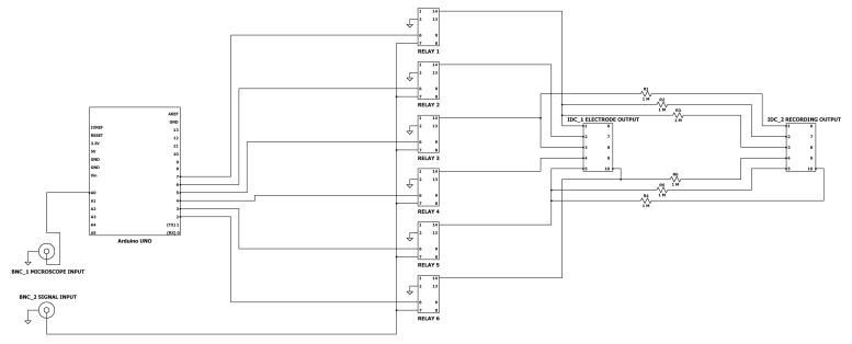
Relay Circuit (The diagram is in Figure 4).
Electron Beam Vapor Deposition System or equivalent alloy deposition method
Table 3. Bespoke electrode dish bill of materials.
| Component | Manufacturer | Manufacturer Part Number | Quantity |
|---|---|---|---|
| Glass-bottom microscope dish | WillCo Wells | HBST-5040 | 4 |
| Araldite two-part epoxy | Araldite | 2457-H | 1 |
| Neodynium Magnets | Magnets4U | SP515-50 | 50 |
| Stainless-steel mask | Laser micromachining | NA | 1 |
| M6 Flat Repair washer | Singularity supplies | NA | 4 |
| Arduino Uno (REV 3) | Arduino | A000073 | 1 |
| Relay | RS PRO | 291-9704 | 7 |
| Phoenix Contact | Phoenix Contact | 1725656 | 4 |
| Female BNC Connector | RS PRO | 526-5864 | 4 |
| Resistor 1MΩ | TE Connectivity | LR1F1M0 | 7 |
| Prototyping Breadboard | Vero Technologies | 01-0021 | 1 |
| 10-way IDC connector (Male) | RS PRO | 625-7252 | 7 |
| 10-way IDC connector (Female) | RS PRO | 625-7369 | 4 |
| 10-way Ribbon Cable Reel | RS PRO | 360-093 | 1 |
| 2.54 mm pitch Header Pins | RS PRO | 251-8121 | 3 |
| Breadboard Jumper Wire | RS PRO | 791-6463 | 1 |
Figure 4. Relay Circuit Diagram.
Detailed schematic for construction of the relay circuit.
Note: Items #5-8 are not necessary with CytePulse method.
Supplementary Equipment
pH meter or testing strips
Weighing scales
Shaking incubator
Adjustable volume pipettes ranging from 0.1 μl to 1,000 μl
Measuring cylinder or serological pipettes ranging from 5-100 ml
Scalpel
Tweezers
-
Bunsen Burner
Table 1. List of equipment for Example Essential Equipment.
Essential Equipment Main text Reference Founding Study Equipment Multi-stage Fluorescence MicroscopeLeica DMi8 microscope with Leica CTR advanced electronics box (Leica) Incubation Chamber PeCon GmbH (PeCon) Temperature Controller TempController 2000-2 heater unit (Pecon) Fluorescent Light Source Lumencor SOLA SE Light Engine light source (Lumencor) Arbitrary Function Generator Tektronix AFG1062 function generator (RS, catalog number: 898-6858) Bespoke electrode dishes Construction Process: see Procedure ABill of materials: Table 3CytePulse consumables. CytePulse consumables (Cytecom) Relay Circuit Bill of materials: Table 3.Circuit Diagram: Figure 4Electron vapor deposition system Custom-built model II2000EB (Scientific Vacuum Systems)
Software
Microscope Control Software (e.g., MetaMorph, micro-manager [micro-manager.org/])
Arduino IDE (arduino.cc) (not necessary with Cytepulse method)
Image processing software (e.g., Fiji/ImageJ (fiji.sc) ( Schindelin et al., 2012 ))
Data processing software (e.g., Matlab, Anaconda Python/R Distribution [anaconda.com]).
Procedure
For those using the bespoke method, as in Stratford et al. (2019) all steps must be followed. For those using the CytePulse system (Cytecom Ltd), skip to Procedure C “Sample preparation” section. Also, of note, those steps demarcated with an asterisk (*) in the procedure only pertain to those following the bespoke method. If using the CytePulse product and consumables, disregard these steps.
-
Bespoke electrode dish construction
The following methods are based on the use of an electron beam vapor deposition system. Different methods may vary between different constructions. Figure 2 provides an illustrative instruction.
Construct a negative stainless-steel mask (Figure 1). This is done by a Laser Manufacturing Company.
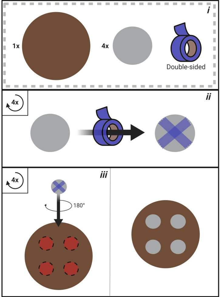
Construct the mounting wafer (Figure 2).
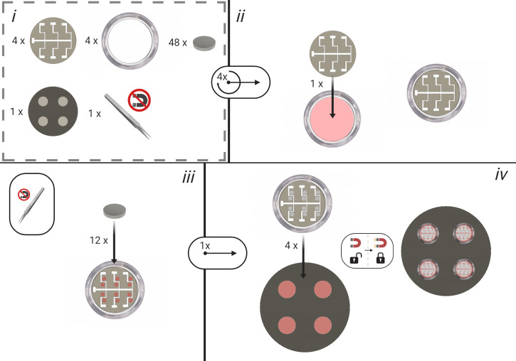
Place the mask into the glass-bottomed microscope dish (Figure 3).
Using non-magnetic tweezers place 12 nickel magnets in positions parallel to each electrode. This ensures that the mask is in contact with the glass.
Mount the dish with mask, magnets and wire onto the stainless-steel platform on the mounting wafer. Place into the electron vapor deposition system.
Deposit the Titanium-Gold Alloy onto the dish using Electron Vapor Deposition (20 nm Ti; 80 nm Au).
Remove the dish from the vapor deposition machine. Check the electrode gap is uninterrupted for each position using an optical microscope.
Solder 7 copper wires of approximately 5 cm to the corresponding pins of a male IDC connector.
Using the soldering iron, create 7 small holes in the plastic rim of the now patterned glass-bottom electrode dish. Feed each of the copper wires through a hole. Secure the male IDC connector to the rim of the dish with Araldite two-part epoxy.
Trim the copper wires to appropriate lengths in order to contact each electrode terminal (including ground) as denoted in Figure 3. Bond the copper wire with conductive graphite epoxy. Once graphite epoxy has solidified, further coat the graphite bond with Araldite two-part epoxy for the purpose of waterproofing.
-
Relay circuit construction
The following circuit is for controlling electrical stimulation across electrodes. Individual electrodes are gated until triggered either manually or after a predetermined number of microscope images, dependent on user microscope configuration. The bill of materials may be found in Table 2. Code to run the circuit is deposited at github (github.com/ConorEd/ElectrodeStimulation).
Solder two female BNC connectors; 6 Relays; 6 1MΩ resistors and two 10-way male IDC connectors to the prototyping board, as shown in Figure 4.
Mount the Arduino UNO microcontroller to the prototyping board and connect the Arduino GPIO pins to the circuit as in Figure 4. This may be accomplished by either extruding breadboard jumper wires from the circuit and plugging them into the pins, or creating a ‘shield’ by soldering 2.54 mm pitch header pins to the circuit board.
Cut ribbon cable to appropriate lengths to reach the microscope and a signal recording device.
Connect two 10-way female IDC connectors to either end of the microscope cable.
Connect the Arduino UNO microcontroler to a computer with the USB B cable and upload the code found at www.github.com/ConorEd/ElectrodeStimulation.
-
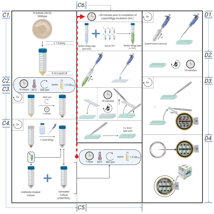
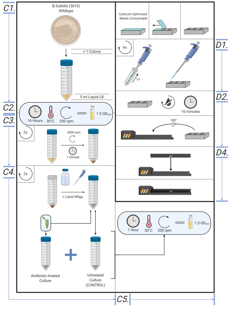
Sample preparation (Figures 5 and 6)
The method may be applied to many bacterial strains or species, subject to appropriate choice of liquid and solid growth media. Wildtype Bacillus subtilis (NCIB3610) or Escherichia coli (K12), at a density of OD600 = 1.5, serves as a good model organism for the method and was used in Stratford et al., 2019 .
The following protocol details the procedure for a culture of wildtype B. subtilis (NCIB3610), OD600 ~1.5. Using cultures treated with or without antibiotic vancomycin, the procedure determines between antibiotic-susceptible and -resistant cells. In Stratford et al. (2019) , we showed that cells treated with UV, ethanol or CCCP show the response distinct from untreated proliferative cells. Cells treated with different antimicrobial agents or procedures can be tested for their electrical responses for rapid AST.
Note: While this method should apply to a broad range of microbes, adaptation may be required for use with species and/or strains with different growth requirements.
LB culture
Place a single colony of B. subtilis into 5 ml aliquots of LB liquid media. Use the standard aseptic technique of microbiology.
Place in overnight in a shaking incubator (37 °C; 200 rpm). Monitor the optical density of cell cultures using a spectrophotometer, the benchmark OD600 for this procedure at the time of experimentation is approximately 1.5.
MSgg liquid culture
Centrifuge B. subtilis LB cultures at 3,220 × g (4,000 rpm) for 5 min; retain the pellet and discard the liquid supernatant.
Resuspend the pellets in the equal volume of liquid MSgg media supplemented with or without vancomycin (or other antimicrobial agents).
Place the culture in a shaking incubator (30 °C; 200 rpm) for 1 h.
Creating agar pads *-
~30 min prior to retrieving the cultures, create the agar padsPlace a microscope cover glass on Parafilm, this ensures the liquid MSgg agar solution remains on the cover glass. Add 1 ml of liquid MSgg agar to a single 22 x 22 mm glass slip, carefully covering the whole slip.
- Immediately place another coverslip on top of the agar, then wait for the agar to solidify. Avoid bubbles to be formed.
- Using tweezers and scalpel, prize the top glass slide off the solid agar, then cut the agar into ~50 mm2 square pads.
-
Loading samples into electrode dish or Cytecom sample holder (Figures 5 and 6)
Add 1.5 μl of cell suspension to each of the agar pads, ensuring the droplet is central and not touching edges of the pad, to prevent lateral pad drifts due to bacterial growth.
Wait 10 min for the drop to dry into the agar pad at room temperature.
-
Using a scalpel and tweezers, slowly lift the agar pad from the bottom and flip onto the electrode, sample side down, so as the sample is in direct contact with the electrode.*
Note: The agar pads can be very fragile, take care not to break or scratch agar pads. Make sure to place the inoculated side facing the electrode.
-
Close the lid on the dish or Cytecom sample holder to prevent sample drying.
Note: If using the Bespoke electrode dish, ensure Parafilm seals the dish shut, to prevent excessive moisture loss from the samples.
-
Preparing sample for microscopy
Secure the dish in the microscope stage insert. If using an oil immersion lens, add immersion oil onto the bottom of the dish or Cytecom sample holder, over each electrode.
Place the stage insert onto the microscope stage.
Open MetaMorph (or equivalent microscope operating software).
-
Locate the position of an electrode and find the correct focus under phase contrast, DIC or brightfield illumination. Save the position of electrode using the microscope software. Repeat this for all 6 electrodes.
Note: Add a ‘rest’ position well away from the electrodes, this should be a place for the objective to remain away from the electrodes between imaging sequences. This helps prevent the pads from drying out.
Leave the sample to settle in the microscope chamber for 1 h at 30 °C to prevent focus drift due to thermal shift.
-
Time-lapse microscopy settings
Set the microscope parameters as per Table 4. Time-lapse is taken for each position separately.
Upload code (https://github.com/ConorEd/ElectrodeStimulation) to the Arduino UNO.* microcontroller, ensuring all relays are set to be closed. Either manual or microscope-triggered relay control may be set prior to upload within the Arduino IDE.
Verify that the electrical stimulation settings are correct (as per Table 5).
Turn on the signal generator.*
Connect the electrode dish to the device via IDC connector (Figure 7).
Start image acquisition through the microscope software.
Figure 2. Mounting wafer construction process.
i. Materials required for mounting wafer construction (1x stainless steel mounting wafer; 4x stainless steel washer; double-sided adhesive tape). ii. Apply double-sided adhesive tape to the bottom of each washer. iii. Secure each washer to the mounting wafer.
Figure 1. Negative electrode mask.

Diagram of the negative electrode mask for construction of bespoke electrode dishes.
Figure 3. Bespoke Electrode Dish Construction; Steps A3-A6.
All numbers correspond to their respective steps within the bespoke electrode construction process.
Table 2. List of equipment for Example Supplementary Equipment.
| Supplementary Equipment | |
| Main text Reference | Founding Study Equipment |
| pH Meter | pH Meter (Fisher-Scientific, catalog number: AE-150) |
| Weighing Scales | Analytical balance (Fisherbrand, catalog number: PS100) |
| Shaking Incubator | Shaking incubator (Labnet, catalog number: 311DS) |
| Adjustable Volume Pipettes | Adjustable Volume Pipettes (Eppendorf, Research Plus) |
| Spectrophotometer | Jenway 7305 Spectrophotometer |
Figure 5. Overview of the bespoke protocol, from cell culture to microscope.
Illustrative diagram for creating cell culture, MSgg liquid culture, creating agar pads and loading samples into Cytecom sample holder.
Figure 6. Overview of the cytecom protocol; from cell culture to microscope.
Si. Creating Cell Cultures (Method found in supplementary information). Ci. MSgg Liquid Culture. D. Loading samples into the Cytecom sample holder.
Table 4. Time-lapse Microscopy Parameters.
| Parameter | Setting |
| Total Duration | 1 min |
| Image Interval | 500 ms |
| Wavelength(s) | 434 nm (CFP Filter) |
| Exposure Time | 150 ms |
| Fluorescent Light Intensity | X |
Table 5. Electrical stimuli parameters.
| Parameter | Setting |
| Duration | 2,500 ms |
| Waveform | Sine |
| Frequency | 100 Hz |
| Voltage | ± 1.5 V |
| Offset | 0 V |
Figure 7. Connecting dish to device.
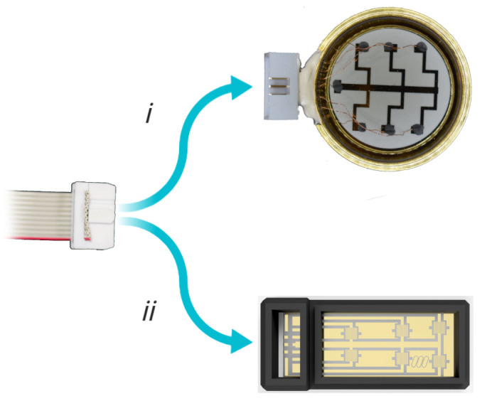
Connect the signal output IDC connector to i) the bespoke dish or ii) CytePulse stage insert, respectively.
Data analysis
-
Load the time-lapse image series in Fiji/ImageJ ( Schindelin et al., 2012 ) (or, equilibrant image analysis software)
Note: It is advisable to play the dataset as a movie to ensure there is no focus drifting, image drifts or bubble formation by electrolysis.
Add regions of interest (ROIs) around individual cells using ROI manager in ImageJ.
Use multi-measures function in ROI manager to measure the intensity values over time. In the founding study, we observed that fluorescence intensity increases in proliferative cells while decreases in inhibited cells.
Recipes
Note: All Media need to be autoclaved and treated with standard microbiology aseptic techniques.
-
LB
Mix 25 g/L as directed on the bottle
-
0.5 M potassium phosphate buffer (pH 7)
Mix 68.5 ml 1 M K2HPO4 and 31.5 ml 1 M KH2PO4
Add 100 ml of water to dilute down to 0.5 M
-
1 M MOPS buffer
Make up 1 mole MOPS salt into 900 ml water
Titrate the pH to 7.0 using NaOH
Mass up to 1 L
-
Modified MSgg
20 ml sterile MillQ water
200 μl 1 M MOPS buffer
200 μl 0.5 M potassium phosphate buffer
-
For MSgg Agar only: 0.3 g agar
Note: Autoclave after adding ingredients 1)-3) [1)-4) in the case of solid MSgg agar]. Add ingredients 5)-14) [5)-15) in the case of solid MSgg agar] just prior to use of the media in the procedure.
200 μl of 50% glycerol (v/v)
200 μl of 25% glucose (w/v)
400 μl of 25% L-Glutamic acid (w/v)
200 μl of 0.1 M Ammonium chloride
20 μl of 0.7 M CaCl2
20 μl of 2 M MgCl2
20 μl of 0.1 M FeCl3
20 μl of 0.05 M MnCl2
0.4 μl of 0.1 M Thiamine
0.2 μl of 0.1 M ZnCl2
For MSgg Agar only: 20 μl of 10 mM ThT
For AST, supplement with antimicrobial agents as needed
Acknowledgments
This protocol is adapted from Stratford et al., 2019 . The work is supported by Biotechnology and Biological Sciences Research Council (BBSRC)/Engineering and Physical Sciences Research Council (EPSRC) grant to the Warwick Integrative Synthetic Biology Centre (Grant BB/M017982/1).
Competing interests
JPS and MA are the founder and shareholders of Cytecom Ltd (Cytecom.co.uk). JPS and CLAE are employees of Cytecom Ltd. JPS and MA have filed a patent for the reported technology.
Citation
Readers should cite both the Bio-protocol article and the original research article where this protocol was used.
References
- 1. Ahmed A., Rushworth J. V., Hirst N. A. and Millner P. A.(2014). Biosensors for whole-cell bacterial detection. Clin Microbiol Rev 27(3): 631-646. [DOI] [PMC free article] [PubMed] [Google Scholar]
- 2. Benarroch J. M. and Asally M.(2020). The microbiologist’s guide to membrane potential dynamics. Trends in Microbiology. [DOI] [PubMed] [Google Scholar]
- 3. Bruni G. N., Weekley R. A., Dodd B. J. T. and Kralj J. M.(2017). Voltage-gated calcium flux mediates Escherichia coli mechanosensation . Proc Natl Acad Sci U S A 114(35): 9445-9450. [DOI] [PMC free article] [PubMed] [Google Scholar]
- 4. Damper P. D. and Epstein W.(1981). Role of the membrane potential in bacterial resistance to aminoglycoside antibiotics. Antimicrob Agents Chemother 20(6): 803-808. [DOI] [PMC free article] [PubMed] [Google Scholar]
- 5. Iqbal S. S., Mayo M. W., Bruno J. G., Bronk B. V., Batt C. A. and Chambers J. P.(2000). A review of molecular recognition technologies for detection of biological threat agents. Biosens Bioelectron 15(11-12): 549-578. [DOI] [PubMed] [Google Scholar]
- 6. Prindle A., Liu J., Asally M., Ly S., Garcia-Ojalvo J. and Süel G. M.(2015). Ion channels enable electrical communication in bacterial communities. Nature 527(7576): 59-63. [DOI] [PMC free article] [PubMed] [Google Scholar]
- 7. Schindelin J., Arganda-Carreras I., Frise E., Kaynig V., Longair M., Pietzsch T., Preibisch S., Rueden C., Saalfeld S., Schmid B., Tinevez J. Y., White D. J., Hartenstein V., Eliceiri K., Tomancak P. and Cardona A.(2012). Fiji: an open-source platform for biological-image analysis. Nat Methods 9(7): 676-682. [DOI] [PMC free article] [PubMed] [Google Scholar]
- 8. Sirec T., Benarroch J. M., Buffard P., Garcia-Ojalvo J. and Asally M.(2019). Electrical polarization enables integrative quality control during bacterial differentiation into spores. iScience 16: 378-389. [DOI] [PMC free article] [PubMed] [Google Scholar]
- 9. Strahl H. and Hamoen L. W.(2010). Membrane potential is important for bacterial cell division. Proc Natl Acad Sci U S A 107(27): 12281-12286. [DOI] [PMC free article] [PubMed] [Google Scholar]
- 10. Stratford J. P., Edwards C. L. A., Ghanshyam M. J., Malyshev D., Delise M. A., Hayashi Y. and Asally M.(2019). Electrically induced bacterial membrane-potential dynamics correspond to cellular proliferation capacity. Proc Natl Acad Sci U S A 116(19): 9552-9557. [DOI] [PMC free article] [PubMed] [Google Scholar]
- 11. Sträuber H. and Müller S.(2010). Viability states of bacteria-specific mechanisms of selected probes. Cytometry A 77(7): 623-634. [DOI] [PubMed] [Google Scholar]


