

Summary
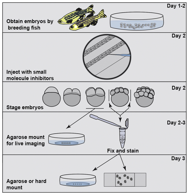
During the earliest division stages, zebrafish embryos have large cells that divide rapidly and synchronously to create a cellular layer on top of the yolk. Here, we describe a protocol for monitoring spindle dynamics during these early embryonic divisions. We outline techniques for injecting zebrafish embryos with small-molecule inhibitors toward polo-like kinases, preparing and mounting embryos for three-dimensional imaging using confocal microscopy. These techniques are used to understand how the early zebrafish embryo’s centrosome constructs the mitotic spindle.
For complete details on the use and execution of this protocol, please refer to Rathbun et al. (2020).
Subject areas: Cell biology, Microscopy, Model organisms
Graphical abstract
Highlights
-
•
Breeding and obtaining zebrafish embryos to monitor spindle dynamics
-
•
Zebrafish embryo microinjection to introduce polo-like kinase (PLK1/4) inhibitors
-
•
Mounting of live and fixed zebrafish embryo for early embryonic studies
-
•
Imaging live and fixed zebrafish embryos using confocal microscope
During the earliest division stages, zebrafish embryos have large cells that divide rapidly and synchronously to create a cellular layer on top of the yolk. Here, we describe a protocol for monitoring spindle dynamics during these early embryonic divisions. We outline techniques for injecting zebrafish embryos with small-molecule inhibitors toward polo-like kinases, preparing and mounting embryos for three-dimensional imaging using confocal microscopy. These techniques are used to understand how the early zebrafish embryo’s centrosome constructs the mitotic spindle.
Before you begin
Note: Prepare injection plates. The injection plate is 3% agarose plate molded to form troughs for fish embryos and is stored at 4°C when not in use (Figure 1). Ensure that injection plates warm to 20°C–23°C prior to injecting embryos, as zebrafish developmental timing is slowed in cooler temperatures.
Figure 1.

General setup of microinjection plate
An example of a prepared microinjection plate (A) and the microinjection plate mold (B) used to produce the visualized troughs in the agarose plate to hold embryos is displayed. An example of the microinjection plate with embryos placed in troughs ready for injection is shown (C), the plate is rotated so the embryos run diagonally for ease of injection; Injection needle is displayed. Injection setup with stereoscope connected to needle holder (D) and manipulator (E), as well as microinjector (F) are shown.
Preparation of injection needle
Timing: 5 min
-
1.
Open the lid of the PUL-1000 Micropipette puller to access the carriages and load the needle (Figure 2A).
-
2.
Make sure the carriages are slid back together before loading the capillary glass (Figure 2C).
-
3.
Place capillary glass into the groove from one side. Then slide it through the heating filament into the other side, making sure it is centered with respect to the heating filament.
-
4.
Secure capillary glass micropipette with clamps.
-
5.
Select the appropriate program using the arrow keys.
Note: We use the following parameters: heat at 650 (heat index), force at 60 (g), distance at 9.99 (mm) and delay at 0 (seconds), refer to Figure 2B.
-
6.
Press start to run the program.
-
7.
Secure the needles by mounting them in modeling clay in 100 mm plate.
Note: Refer to Figure 2C for summary.
Figure 2.

Schematic procedure of microneedle preparation
The micropipette puller device, the PUL-1000 (A) by World Precision instruments with needle pulling parameters (B) is displayed. The schematic (C) represents the pulling procedure detailed in “Injection Needle Preparation.” Briefly, open the lid (a′), slide the capillary glass through the heating filament (b′), secure the capillary glass with clamps (c′), and run the program to produce two needles with fused ends (d′).
Setting up Zebrafish for breeding
-
8.Setting up breeding pairs the night before an experiment
-
a.Select and remove the tank of interest from the system rack:
-
i.The tanks must not have bred within the past 14 days or have been set up to breed (no embryos produced) within the past 5 days.
-
ii.If the tanks have come from the same clutch, the fish may be bred together.
-
iii.If tanks are bred from different clutches (with different birthdays and parents), note the sexes of each transgenic line from each tank so that they can be separated afterwards.Note: Information about sexing the female and male fish is described in Westerfield (2000). Additionally, use link for pdf of relevant section: http://www.zfic.org/common%20techniques/Gender%20identification%20guide.pdf.
-
i.
-
b.Set up the breeding tanks (Figure 3).
-
i.Place an inner mesh-bottomed tank within a normal outer tank.
-
ii.Fill the tank with a few inches of system water.
-
iii.Place a divider within the inner mesh-bottomed tank.
-
i.
-
c.Add fish to the breeding tank.
-
i.Gently remove the fish from their system tank and place into the breeding tank using a fish net.
-
ii.Place the male fish on one side of the divider and female fish on the other side.
-
iii.Never use more males than females. The males will fight if there are not enough females.
-
iv.There should be no more than 4 fish per breeding tank (2 males and 2 females).
-
i.
-
a.
Figure 3.

Breeding tank setup
Tank setup begins with the outer tank (A) of the breeding tank set. The inner meshed tank (B) is placed inside the outer tank. The divider (C) is placed in center slots of the meshed inner tank. The lid (D) covers the top of assembled breeding tank. Image of fully assembled breeding tank is shown (E).
Key resources table
| REAGENT or RESOURCE | SOURCE | IDENTIFIER |
|---|---|---|
| Antibodies | ||
| Rabbit anti-γ-tubulin (1:200) | Sigma-Aldrich | Cat# T5192, RRID: AB_261690 |
| DAPI | Sigma-Aldrich | Cat# D9542-10MG |
| Donkey anti-rabbit Alexa Fluor 488 (1:200) | Life Technologies | Cat# A21206, RRID: AB_2535792 |
| Donkey anti-rabbit Alexa Fluor 647 (1:200) | Life Technologies | Cat# A31573, RRID: AB_2536183 |
| Chemicals, peptides, and recombinant proteins | ||
| Agarose | Thermo Fisher | Cat# 16520100 |
| BI2536 | Selleck Chemicals | Cat# S1109 |
| BSA | Fisher Scientific | Cat# BP1600-100 |
| Centrinone B | R&D Systems | Cat# 5690 |
| Dimethylsulfoxide | Fisher Scientific | Cat# BP231100 |
| Methylene blue 100 g | Fisher Scientific | Cat# BP117100 |
| Paraformaldehyde | Fisher Scientific | Cat# AA433689M |
| PBS | Fisher Scientific | Cat# 10010023 |
| ProLong Gold | Fisher Scientific | Cat# P36934 |
| Sea Salt - 42 Lb. Box Crystal Sea Bioassay Formula | Aquaneering | Cat# SCS50BA3 |
| Triton X-100 | Fisher Scientific | Cat# BP151500 |
| Tween 20 | Thermo Fisher | Cat# BP337500 |
| UltraPure low melting point agarose | Thermo Fisher Scientific | Cat# 16520100 |
| Experimental models: organisms/strains | ||
| Zebrafish | Gift from Solnica-Krezel Lab, generated by Harris Lab | Tg(-5actb2:cetn4-GFP) |
| Software and algorithms | ||
| ImageJ/FIJI | (Schindelin et al., 2012) | https://imagej.net/Fiji |
| LAS-X software | Leica Microsystems | https://www.leica-microsystems.com/products/microscope-software/p/leica-las-x-ls/ |
| Other | ||
| 35 mm dish, no. 1.5 coverslip, 20 mm glass diameter, uncoated | MatTek Corporation | Cat# P35G-1.5-20-C |
| Capillary glass; thin wall borosilicate glass without filament; OD 1.0 mm, ID 0.75 mm | Sutter Instrument Company | Cat# B100-75-10 |
| Crossing tank set (1.0-L) clear polycarbonate with lid and insert | Aquaneering | Cat# ZHCT100 |
| Dumont tweezer, style 5 | Electron Microscopy Sciences | Cat# 0209-5-PO |
| Eppendorf FemtoJet microinjector, microloader tips | Krackeler Scientific | Cat# 930001007 |
| Fisherbrand disposable borosilicate glass Pasteur pipets | Fisher Scientific | Cat# 13-678-20C |
| Fisherbrand Petri DISHES with clear lid, 60 mm | Fisher Scientific | Cat# FB0875713A |
| Fisherbrand Petri dishes, stackable lid, 100 mm | Fisher Scientific | Cat# FB0875712 |
| Fisherbrand standard disposable transfer pipettes, nongraduated; length, 5.875 in; capacity, 7.7 mL | Fisher Scientific | Cat# 13-711-7M |
| I-34 microinjection molds | Adaptive Science Tools | Cat# i34 |
| Magnetic holder base | Kanetec | Cat#: MB-B |
| Leica S9i stereoscope with integrated camera | Leica Microsystems | Cat# S9i |
| Leica TCS SP8 laser scanning confocal microscope | Leica Microsystems | Cat# DMi8 |
| Marina 3-inch blue fine nylon net with 10-inch handle | Amazon | Cat# ASIN B0002AQJH6 |
| Penn Plax brine shrimp aquarium net | Amazon | Cat# ASIN B0002APXLY |
| PLI-100A acrylic pipette holder for 1.0 mm pipettes | Werner instruments | Cat# 64-1626 |
| PLI-100A picoliter injector | Werner instruments | Cat# 64-1735 |
| PUL-1000 microprocessor-controlled micropipette puller | World Precision Instruments | Cat# PUL-1000 |
| Sargent Art 22-4084 1-pound solid color modeling clay, gray | Amazon | Cat# ASINB003FGVNS4 |
| Square cover glass, #1.5 thickness, 22 mm, 100 pack | Harvard Apparatus | Cat# 64-0721 |
| Standard manual control micromanipulator | Werner Instruments | Cat# MM-33R |
Materials and equipment
Embryo water
| Reagent | Final concentration | Amount |
|---|---|---|
| Sea salt | 0.3% | 3 g |
| Methylene blue | 0.01 | 100 mL |
| dH2O | 99.69% | 996.9 mL |
| Total | n/a | 1,000 mL |
Store at 20°C–23°C for up to 3 weeks.
PFA/Fixing solution
| Reagent | Final concentration | Amount |
|---|---|---|
| Paraformaldehyde (PFA) | 4% | 4 g |
| PBS | 1× | 96 mL |
| Total | n/a | 100 mL |
Prepare in a flask. Seal the flask with tissue to reduce fuming. Spin on stir plate at 150°C and 200 rpm in fume hood. Store in fume hood, at 20°C–23°C for no more than 2 weeks.
CRITICAL: Paraformaldehyde is flammable in its solid form. It causes eye, skin, and respiratory tract irritation. It is harmful if inhaled, swallowed, or absorbed through the skin. Wear gloves when preparing this solution.
Fish wash/blocking solution
| Reagent | Final concentration | Amount |
|---|---|---|
| DMSO | 1.0% | 2.5 mL |
| BSA | 1.0% | 2.5 g |
| Triton X | 0.5% | 1.25 mL |
| PBS | 1× | 243.75 mL |
| Total | n/a | 250 mL |
Spin on stir plate until contents are homogenized, then filter sterilize. Store at 4°C for no more than 3 weeks.
Note: Start with 20% Tween stock solution (10 mL Tween in 40 mL dH2O).
PBST solution
| Reagent | Final concentration | Amount |
|---|---|---|
| Tween-20 (20%) | 0.5% | 1.25 mL |
| PBS | 1× | 248.75 mL |
| Total | n/a | 250 mL |
Spin on stir plate until contents are homogenized, then filter sterilize. Store at 4°C for no more than 3 weeks.
2% mounting Agarose
| Reagent | Final concentration | Amount |
|---|---|---|
| Ultra-low melting agarose | 2% | 2 g |
| dH2O | 98% | 98 mL |
| Total | n/a | 100 mL |
Heat in the microwave in 30 s intervals for 1–3 min. Make sure to gently swirl contents between each interval until all the agarose has melted. Aliquot into 1.5 mL tubes. Store at 20°C–23°C for up to 2 months. When needed, melt aliquoted agarose in a heat block set at 65.5°C.
Step-by-step method details
Chemical injections of embryos
Introduce different agents, such as small-molecule inhibitors (in our case BI2536 and Centrinone) or vehicle control (in our case DMSO) into the developing embryo. This step should be performed when embryos are at the 1-cell stage.
Note: A Lecia S9i stereomicroscope was used for injections along with microinjector and micromanipulator (see Key resources table for information). A video description of microinjections can be found on JoVE (JoVE Science Education Database, 2020). https://www.jove.com/v/5130/zebrafish-microinjection-techniques.
-
1.Injection Set Up (Figures 1D and 1E)
-
a.Dilute the solution to be injected before beginning (in our case we injected DMSO concentration of 0.1%–1% and BI2536 or centrinone B final concentration of 100 nM or 1 μM diluted in embryo water).Note: We diluted 1.3 μL of 1 mM drug into 8.7 μL dH2O and 1.3 μL of 1 mM drug into 98.7 μL dH2O to achieve a final concentration of 1 μM and 100 nΜ upon injection of 1 nL of diluted drugs in fish embryo volume which we estimate to be 130 μm3.
-
b.Prepare 10 μL of solution so that there is extra in case of needle breakage.
-
c.Turn the injector on and open the gas tank.
-
d.Let the injection plate warm up to 20°C–23°C.
-
a.
-
2.Loading the needle
-
a.Load the injection solution into the needle by using a pipette and needle-loading pipette tips (see Key resources table for catalog number). Pipette tip needs to reach the end of the needle to verify there is minimal air present at the end of the needle. If any air bubbles are present in the injection solution, remove them using pipette suction.
-
b.Unscrew the barrel piece from micromanipulator and insert the flat end of the needle. Then screw the barrel back into the micromanipulator.
-
a.
-
3.Obtaining the embryos
-
a.Pull the dividers the morning after fish are set up for breeding.Note: Zebrafish breed in the morning in the wild, so dividers should be pulled when fish room lights turn on (mimics sunrise).
-
i.Move the inner mesh-bottomed tank (with the divider) to another outer tank with new system water.
-
ii.Pull the divider to allow the fish to mix and breed.
-
i.
-
b.Collect the embryos (see Methods Video S1):
-
i.Remove the fish by placing the inner mesh-bottomed tank (with the fish) into a separate outer tank filled with system water.
-
ii.Pour the system water containing the embryos through a white mesh net to collect the embryos.
-
iii.Fill the empty tank with more system water and run it through the white mesh net a second time to ensure that all the embryos were collected.
-
iv.Fill a Petri dish with embryo water and label it with the parent’s transgenic line as well as the embryo’s date of birth.
-
v.Reverse the white mesh net to have the embryos facing outward toward the water.
-
vi.Gently touch the embryos to the water within the Petri dish. They should stick and sink to the bottom.
-
vii.Bring embryos to injection station.
Methods Video S1. Video of embryo collectionTo collect embryos, move the inner mesh tank with fish in it to a new outer tank containing fresh fish system water. Run the water containing embryos through the mesh net to collect embryos. Reverse the net outward then gently touch the embryos to the embryo water surface in Petri dish. The embryos are ready for incubation. Relate to (Chemical Injections of Embryo, step 3b).Download video file (19.6MB, flv) -
i.
-
a.
-
4.Preparing embryos for injection
-
a.Add embryo water to the injection plate.
-
b.Transfer the embryos carefully to the plate using a transfer pipette (refer to Key resources table for catalog number).
-
c.Using a glass pipette with a melted tip, carefully push the embryos into the troughs. Be sure to leave space at the end of each row to make removing embryos from the rows easier (See Figure 1 for example).
-
a.
-
5.Calibrating your needle
-
a.Using the Stereomicroscope, cut the needle with forceps. The needles are fused at the end when made with a needle puller. Verify that the needle is no longer fused after cutting so that liquid can flow through the needle.Note: The location that the needle is cut by the forceps determines the thickness/flexibility of the needle. If the needle is too thin, it will be too flimsy to poke through the chorion without breaking. If this is the case, the needle can be cut again with forceps to remove a bit more length. However, the needle also needs to be thin enough to poke through the chorion and embryos without causing significant damage. If the needle is causing significant damage to the embryo upon injection, a new needle should be loaded and cut.
-
b.After cutting the needle, zoom into 5× magnification on the microscope (see Figure 1D). Adjust the injection time and pressure (Figure 1F) until a liquid droplet that is 6 μm in diameter is formed. This produces a droplet of approximately 1 nL.Note: If the liquid droplet is changing in size, the balance on the microinjector (Figure 1F) needs to be adjusted with the balance knob. Turn this knob gently until the droplet maintains a consistent size on the needle.
-
c.Once the needle is cut and calibrated, you are able to inject.
-
a.
-
6.Injecting
-
a.Turn your injector plates until the troughs run at a diagonal. This will ensure that you do not puncture the agarose and break the needle (see Figure 1C for example).
-
b.Position the needle so that the x axis knob on the micromanipulator is the only one you need to adjust to inject the embryos (Figure 1E).
-
c.To inject, use the micromanipulator to puncture the embryo with the needle targeting the yolk. Press the foot pedal, remove the needle, and move the plate to the next embryo. Ensure that the needle is removed from the embryo before the plate is adjusted so that the embryo is not damaged.
-
a.
-
7.After injecting
-
a.Once done, carefully adjust the micromanipulator to bring the needle as high as possible above the plate. Remove the needle from the micromanipulator and dispose of it in the sharp’s container.
-
b.Use the glass pipette with melted tip to remove the embryos from their troughs. Push the embryo upwards to dislodge it and collect embryos in a 60 mm petri-plate for incubation at 28.5°C until fixing/imaging.
-
c.Using DI water, rinse the agarose plate and store upside down in the refrigerator.
-
d.Turn off the microinjector and close the gas tank.
-
a.
Agarose mounting for live imaging
Live visualization of subcellular structures (in our case we image the centrosomes) in the early zebrafish embryos starting at 4-cell stage and up to post mid-blastula transition.
Note: Transgenic lines or embryos with fluorescently tagged structures are required for this option (in our case we used the centrin-GFP line).
-
8.
Wait until the embryos reach the 4-cell stage (see Figure 4C for example; refer to Kimmel et al. (1995) for more detailed staging of the developing zebrafish embryo).
-
9.
Using a disposable transfer pipette move the embryos to matTek plate (containing glass coverslip bottom; see Methods Video S2).
Figure 4.

Staging of zebrafish embryos to determine fixation time
Zebrafish embryo developmental stages starting with the 1-cell stage (A), 2-cell stage (B), 4-cell stage (C), 8-cell stage (D), and 16-cell stage (E) are shown. Scale bar, 50 mm. Arrows indicate stage at which 8- and 16-cell stage embryos should be fixed.
-
10.
Remove as much embryo water as possible.
-
11.
Add ∼300–500 μL low melting point agarose to the matTek plate coverslip. The agarose melts at 65.5°C (we set our heat block to 70°C). As hot agarose will damage the embryos, ensure that the agarose cools slightly before covering embryos. Agarose should be warm enough to remain liquid, but not hot enough to harm live embryos.
-
12.
Using a 1 mL syringe needle, spread the agarose to cover the embryos and coverslip of the matTek plate. It is important to completely cover the glass coverslip by contacting all edges to ensure that the agarose and embryos do not move during imaging.
-
13.
Using the tip of the syringe needle, rotate the embryos so that the cells are facing downwards (toward the coverslip).
-
14.
Gently push the embryos using the syringe needle to place them as close to the coverslip as possible.
-
15.
Allow the agarose to solidify (1–2 min). Agarose will turn slightly opaque when set.
-
16.
Add embryo water to matTek dish to prevent agarose from over drying and shrinking while imaging.
-
17.Embryos are ready for immediate live imaging.
-
a.If imaging at a later stage, in our case 8- and 16-cell stages, wait until the agarose-mounted embryos reach the appropriate stage (outlined in Figure 4).
-
a.
When embryos reach the 4-cell stage, move them to a matTek plate. Remove as much embryo water as possible then add ∼300–500 μL low melting point agarose. Use a 1 mL syringe needle to spread the agarose to cover the embryos and coverslip of the matTek plate. Rotate the embryos so that the cells are facing downwards (toward the coverslip). Gently push the embryos using the needle to place them as close to the coverslip as possible. Allow the agarose to solidify then add embryo water to matTek dish to prevent agarose from over drying and shrinking while imaging. Relate to (Agarose Mounting for Live Imaging, steps 8–17).
Immunohistochemistry of Zebrafish embryos
Visualize subcellular structures (such as the centrosomes) of a zebrafish embryo. In our experiments we used this protocol on embryos ranging from 4 cell stage to post mid-blastula transition, but it can be used on embryos beyond these stages.
-
18.Once at the desired developmental stage (Figure 4), transfer embryos into a 1.5 mL Eppendorf tube
-
a.Replace embryo water with fixing solution pre-warmed to 28.5°C.
-
b.Incubate embryos in fixing solution for 2 h at 20°C–23°C with frequent and gentle agitation.
-
c.Incubate tubes containing embryos and fixing solution at 4°C for 8–24 h.
-
a.
-
19.
Remove fixing solution and wash embryos from previous step with PBST three times, 5 min each.
-
20.Dechorionate the embryos:
-
a.Transfer embryos into a 60 mm plate containing PBST and remove chorions using forceps with thin tips.
-
b.Transfer the embryos back into a 1.5 mL Eppendorf tubes.
-
a.
-
21.
Remove PBST and block by adding 1 mL fish wash solution.
-
22.
Incubate embryos in fish wash solution for 1 h at 20°C–23°C.
-
23.Remove fish wash solution and incubate embryos in 200 μL primary antibody solution (in our case, we used antibodies against human γ-tubulin at 1:200 dilution in fish wash solution).
-
a.First option: incubate for 4 h at 20°C–23°C.
-
b.Second option: incubate 8–24 h at 4°C.
-
a.
Note: We recommend the second incubation option.
Pause point: The experiment can be paused for up to 24 h while embryos are incubating in primary antibody.
-
24.
Remove primary antibody solution and wash embryos 5 times with fish wash solution. Wash steps should be 5 min each.
-
25.
Incubate embryos in fish wash solution for 30–60 min at 20°C–23°C to block.
-
26.Remove fish wash solution and incubate embryos in secondary antibody diluted 1:200 in wash solution. Incubation time should not exceed that used for primary antibodies.
-
a.First option: incubate for 8–24 h at 4°C (only if embryos were incubated in primary antibodies for 8–24 h).
-
b.Second option: incubate for 3–4 h 20°C–23°C.
-
a.
Note: The length of incubation time in secondary antibody solution should not exceed time of incubation in primary antibody solution.
-
27.
Remove secondary antibody solution and wash embryos 5 times with fish wash solution. Wash steps should be 5 min each.
Optional: Incubate embryos in DAPI diluted 1:1,000 in 1× PBS for 1.5 h at 20°C–23°C. Wash embryos with 1× PBS 3 times. Washes should be 5 min each.
Choice 1: Agarose mounting fixed embryos
This protocol was performed on embryos ranging from 8 cell stage to post mid-blastula transition, but it can be used on embryos beyond these stages.
-
28.
Using a disposable transfer pipette, move the fixed and stained embryos to matTek plate (containing glass coverslip bottom).
-
29.
Using 1 mL syringe with needle, remove as much embryo water as possible (refer to Methods Video S2 for agarose mounting technique).
-
30.
Add ∼ 300–500 μL low melting agarose to the matTek plate coverslip.
-
31.
Using a 1 mL syringe with needle, spread the agarose to cover the embryos and coverslip of the matTek plate. It is important to completely cover the glass coverslip by contacting all edges to ensure that the agarose and embryos do not move during imaging.
-
32.
Using the tip of the syringe needle, rotate the embryos so that the cells are facing down (toward the coverslip).
-
33.
Gently push the embryos using the syringe needle to place them as close to the coverslip as possible.
-
34.
Allow the agarose to solidify (1–2 min).
-
35.
Add embryo water to prevent agarose from over drying and shrinking while imaging.
-
36.
Embryos are ready for imaging.
Choice 2: Hard-mounting with ProLong
Hard-mounting embryos (8-cell stage up to post mid-blastula transition) to allow imaging of cellular structures after staining (Figure 5, Methods Video S3).
-
37.
Place embryos on glass slide.
-
38.
Use two 1 mL syringes attached to 28-gauge × 0.5 inch separate the cell mass from the yolk (as in Figures 5A–5D). Start by placing the tips of the syringe needles on either end of the cells. Use one needle to hold the cells while lifting thus separating the cell mass. Repeat for every embryo.
-
39.
Remove as much yolk as possible from the slides using a transfer pipette as excess yolk debris can obstruct visualizing embryonic cells.
Note: Transfer pipette should be enough to remove most yolk, a few remaining particles should not cause a problem with imaging.
-
40.
Flip the embryo so that the tops of the cells (the side that was not attached to the yolk) is facing away from the glass slide (refer to Figure 5E).
-
41.
Remove as much PBS as possible using a 1 mL syringe.
-
42.
Add 40 μL of ProLong to one side of the cells on the glass slide.
-
43.
Place a No. 1.5 square (22 mm) coverslip on the same side making sure it touches the ProLong, then slowly lower the coverslip.
-
44.
Apply gentle pressure to the coverslip ensure cells are flattened and ProLong is distributed across the coverslip and embryos. Avoid air bubbles.
-
45.
Allow ProLong on slides to harden for 24 h at 20°C–23°C and in the dark before imaging.
Figure 5.

Schematic of the hard-mounting procedure of zebrafish embryo cells
The procedure begins by placing the embryos on glass slide (A). The needle tips of the 1 mL syringes are used to separate cells from yolk (B–D). The separated cells are oriented such that the yolk-free side (side that was not attached to yolk) is facing away from glass slide (E). The cover slip is placed on top of the cells after applying ProLong (F).
To hard-mount fixed embryos, transfer the embryos onto a glass slide. Separate the cell mass from the yolk using the needles of two 1 mL syringes. Remove the yolk from the slide and flip the cells so that the tops of the cells are facing away from the glass slide. Remove excess PBS using a 1 mL syringe. Add 40 μL ProLong onto the glass slide on one side of the cells. Place the edge of coverslip so that it touches ProLong then carefully lower the coverslip. Apply gentle pressure to flatten the cells. Relate to (Hard-Mounting with ProLong, steps 37–45).
Expected outcomes
Example representative images of transgenic live embryos, or hard-mounted and agarose-mounted embryos fixed and stained using this protocol are shown in Figure 6. The maximum projection confocal micrographs of live embryos show centrin at the centrosomes of an 8-cell stage embryo. Maximum projection confocal micrographs of agarose-mounted or hard-mounted stained embryos show centrin-GFP and the human anti-γ-tubulin antibody, respectively, in 8-cell stage embryos.
Figure 6.

Representative confocal micrograph of 8-cell stage embryos
Representative confocal maximum projection (gray inverted LUT) of an 8-cell embryo imaged using an HCX PL FLUOTAR 10×/0.32 objective. The images were taken from a live agarose-mounted centrin-GFP embryo (A), a fixed agarose-mounted centrin-GFP embryo (B) and a fixed hard-mounted embryo stained with anti-γ-tubulin antibody (C) are shown. Darker structures represent protein signal at the centrosomes. Scale bar, 100 μm.
Quantification and statistical analysis
Image acquisition and processing
A Leica SP8 laser scanning confocal microscope (LSCM) was used (Leica, Bannockburn, IL). Imaging was performed using an HCX PL FLUOTAR 10×/0.32 or HC PL APO 40×/1.10 W CORR CS2 0.65 water immersion objective. Images were acquired using LAS-X software and using lightning, a built-in adaptive deconvolution algorithm (https://downloads.leica-microsystems.com/Leica%20TCS%20SP8/Publications/LIGHTNING_WhitePaper.pdf). Acquired Images were processed using FIJI/ImageJ software or Imaris (BitPlane). Imaris is primarily used for free-rotating volumetric visualization of the embryo, whereas FIJI/ImageJ is used for all maximum projections of stacked optical images obtained from embryos.
Parameter selection on a confocal is based on the signal to noise ratio of the fluor being imaged within a specific embryo (refer to Problem 2 for troubleshooting). Thus, specific parameters for laser scanning confocal acquisition vary from embryo to embryo. In our experiments, we have typically found 10% power for 405 laser (50 mW maximum power), 7% for 488 (65 mW maximum power) and 5% for 647 to be ideal. We used optimal z-step size, which is automatically calculated by the Leica software for the objective we use to achieve Nyquist sampling. Bidirectional scanning was performed at a set speed of 700 frames/s. We used the zoom function to make sure the embryo takes up the full field of view (typically ranges between 1.28 and 1.5). We started with a low “Gain” and increased it for each channel until the signal of structure of interest was clearly distinguishable from background and signal to noise seemed sufficient. For spindle length analysis, we imaged embryos with a 10× objective as shown in Figure 6, with x-y dimensions of 0.68 × 0.68 mm2 (1,024 by 1,024 pixel2). Leica’s SP8 user manual and training guide for imaging with the microscope can be found online, see the following link for pdf: https://bsir.bio.fsu.edu/sites/g/files/upcbnu1511/files/leica-sp8-user-guide.pdf
Quantification of cell length and spindle length
We measured cell and spindle length using agarose-mounted embryos. Both measurements were performed on FIJI/ImageJ maximum confocal projections by drawing a line from one end of the structure to the other. For cell length, the length of a line extending along the longest cell axis (usually in the same orientation as mitotic centrosomes) from one side of the membrane to the other was measured for each cell (see Figure 7A). For spindle length, the length of a line extending from the center of one mitotic centrosome to the other was measured for each cell (see Figure 7B).
Figure 7.

Representative images of Fiji measurements
Representative zoomed in images of a 16-cell stage embryo imaged using an HCX PL FLUOTAR 10×/0.32 objective with manually labeled Fiji measurements of cell length (A), spindle length (B) and centrosome area (C). Length measurements were performed using the “straight line segment” tool highlighted with cyan box (A, B). Centrosome area was traced and measured using the “free selection” tool highlighted in cyan box (C).
Quantification of centrosome area
To measure the 2-dimensional area of the centrosome, we used FIJI/ImageJ to draw a boundary around the centrosome in a confocal maximum projection and calculated the area within that boundary (see Figure 7C).
Note: In some cases, embryo cells were hard-mounted (refer to Methods Video S3) or the whole embryo was agar-mounted for these studies (Methods Video S2). When we remove the cells monolayer from the yolk and hard-mount the cells on a glass coverslip, the cells are flattened so that they do not curve along the surface compared to when embryos are agar-mounted and still have their yolk. In this case, 3-dimensional volumetric measurements of the centrosome can be performed using Imaris. When doing this we found no difference in the trend in centrosome sizes between volumetric measurements and 2-dimensional area when hard-mounting the embryos. Therefore, we used the 2-dimensional area as a measure of centrosome size featured in Rathbun et al., 2020.
Limitations
There are different advantages and disadvantages associated with imaging fixed and live embryos. For fixed embryos, hard-mounting is a great tool for studying 2-dimensional structures, and it allows for imaging a larger number of embryos with better resolution due to the short working distance that results from flattening the embryo’s cells. Additionally, the cells of hard-mounted embryos can be preserved for prolonged amounts of time. However, the flattening of the cells with hard-mounting limits the information that can be obtained about the embryos’ morphology, such as the overall shape or volume of the cells. If shape of cells needs to be maintained, agarose mounting of live and/or fixed embryos is suggested. This is because agarose mounting does not flatten the cells and allows for preservation of the embryo’s structure. However, fixed embryos that are mounted with agarose will not last longer than 24 h, so imaging time is limited and needs to occur the same day they are mounted. Agarose mounting is great for live studies because it provides an appropriate environment for the embryo while holding it in place. However, live imaging restricts the number of embryos that can be imaged in a single imaging session due to time constraints, and the thickness of the embryo can also limit the depth of imaging.
Troubleshooting
Problem 1
Embryonic lethality following injection trauma (Chemical injections of embryos, step 6).
Potential solution
Injection trauma can result from injecting too high a concentration of a small-molecule inhibitor. Thus, a titration protocol for drug concentration is highly recommended for maximum optimization. Make sure to control for injection trauma using a vehicle control such as DMSO or water depending on the solubility of the small-molecule inhibitor used.
Problem 2
Decreased signal to noise ratio for γ-tubulin staining (Refer to Image acquisition and processing).
Potential solution
There are many reasons for sub-optimal signal to noise ratios following immunofluorescent protocols. First, the dilution of the primary antibody (in our case an antibody toward human γ-tubulin) might not be optimized for use in zebrafish embryos. Try performing a titration in antibody dilutions starting at 1:100 and going to 1:1,000 dilutions. Second, when testing a new antibody, it is good to check conservation in protein sequences between the species recognized by the antibody compared to zebrafish. In our case, γ-tubulin is highly conserved, and we get optimal signal to noise ratios at 1:200 dilution.
Resource availability
Lead contact
For further information or to request resources/reagents, contact the Lead Contact, Heidi Hehnly (hhehnly@syr.edu).
Materials availability
No new materials were generated for this study.
Data and code availability
This study did not generate any unique datasets or code.
Acknowledgments
This work was supported by National Institutes of Health grants, nos. R00GM107355, R01GM127621, and R01GM130874 (to H.H.), and a Syracuse University ‘Cuse Good-to-Great award.
Author contributions
A.A.A., A.M., and T.C. wrote the protocol, L.I.R. revised a final draft of the protocol, and H.H. oversaw and went through multiple rounds of revisions.
Declaration of interests
The authors declare no competing interests.
Footnotes
Supplemental information can be found online at https://doi.org/10.1016/j.xpro.2020.100293.
References
- Kimmel C.B., Ballard W.W., Kimmel S.R., Ullmann B., Schilling T.F. Stages of embryonic development of the Zebrafish. Dev. Dyn. 1995;203:253–310. doi: 10.1002/aja.1002030302. [DOI] [PubMed] [Google Scholar]
- JoVE Science Education Database . JoVE; 2020. Biology II: Mouse, Zebrafish, and Chick. Zebrafish Microinjection Techniques. [Google Scholar]
- Rathbun L.I., Aljiboury A.A., Bai X., Hall N.A., Manikas J., Amack J.D., Bembenek J.N., Hehnly H. PLK1- and PLK4-mediated asymmetric mitotic centrosome size and positioning in the early zebrafish embryo. Curr. Biol. 2020;30:4519–4527.e3. doi: 10.1016/j.cub.2020.08.074. [DOI] [PMC free article] [PubMed] [Google Scholar]
- Schindelin J., Arganda-Carreras I., Frise E., Kaynig V., Lοngair M., Pietzsch T., Preibisch S., Rueden C., Saalfeld S., Schmid B. Fiji: an open-source platform for biological-image analysis. Nat Methods. 2012;9:676–682. doi: 10.1038/nmeth.2019. [DOI] [PMC free article] [PubMed] [Google Scholar]
- Westerfield M. Fourth Edition. University of Oregon Press; 2000. The zebrafish book. A guide for the laboratory use of zebrafish (Danio rerio) [Google Scholar]
Associated Data
This section collects any data citations, data availability statements, or supplementary materials included in this article.
Supplementary Materials
To collect embryos, move the inner mesh tank with fish in it to a new outer tank containing fresh fish system water. Run the water containing embryos through the mesh net to collect embryos. Reverse the net outward then gently touch the embryos to the embryo water surface in Petri dish. The embryos are ready for incubation. Relate to (Chemical Injections of Embryo, step 3b).
When embryos reach the 4-cell stage, move them to a matTek plate. Remove as much embryo water as possible then add ∼300–500 μL low melting point agarose. Use a 1 mL syringe needle to spread the agarose to cover the embryos and coverslip of the matTek plate. Rotate the embryos so that the cells are facing downwards (toward the coverslip). Gently push the embryos using the needle to place them as close to the coverslip as possible. Allow the agarose to solidify then add embryo water to matTek dish to prevent agarose from over drying and shrinking while imaging. Relate to (Agarose Mounting for Live Imaging, steps 8–17).
To hard-mount fixed embryos, transfer the embryos onto a glass slide. Separate the cell mass from the yolk using the needles of two 1 mL syringes. Remove the yolk from the slide and flip the cells so that the tops of the cells are facing away from the glass slide. Remove excess PBS using a 1 mL syringe. Add 40 μL ProLong onto the glass slide on one side of the cells. Place the edge of coverslip so that it touches ProLong then carefully lower the coverslip. Apply gentle pressure to flatten the cells. Relate to (Hard-Mounting with ProLong, steps 37–45).
Data Availability Statement
This study did not generate any unique datasets or code.