

Abstract
Purpose:
To achieve a superior balance between dosimetry and the delivery efficiency of intensity-modulated proton therapy (IMPT) using as few beams as possible in a single fraction, we optimally vary beams in different fractions.
Methods:
In the optimization, 400~800 feasible noncoplanar beams were included in the candidate pool. For each beam, the doses of all scanning spots covering the target volume and a margin were calculated. The fraction-variant beam orientation optimization (FVBOO) problem was formulated to include three terms: two quadratic dose fidelity terms to penalize the deviation of planning target volume fractional dose and organs at risk (OAR) cumulative doses from prescription, respectively; an L2,1/2-norm group sparsity term to control the number of active beams per fraction to between 1 and 4. The Fast Iterative Shrinkage-Thresholding Algorithm (FISTA) was applied to solve this problem. FVBOO was tested on a patient with base-of-skull (BOS) tumor of 5 fractions (5f) and 30 fractions (30f) with an average number of active beams per fraction varying between 4 and 1. In addition, one bilateral head-and-neck (H&N) patient, and one esophageal cancer (ESG) patient of 30f were tested with about three active beams per fraction. The results were compared with IMPT plans that use fixed beams in each fraction. The fixed beams were selected using the group sparsity term with a fraction-invariant BOO (FIBOO) constraint.
Results:
Varying beams were chosen in either the 5f or 30f FVBOO plans. While similar number of beams per fraction was selected as the FIBOO plan, the FVBOO plans were able to spare the OARs better, with an average reduction of [Dmean, Dmax] from the FIBOO plans by [0.85, 2.08] Relative Biological Effective Gy (GyRBE) in the 5f plan and [1.87, 4.06] GyRBE in the 30f plans. While reducing the number of beams per fraction in the BOS patient, a three-beam/fraction 5f FVBOO plan performs comparably as the four-beam FIBOO plan and a two-beam/fraction 30f FVBOO plan still provides superior dosimetry.
Conclusion:
Fraction-variant beam orientation optimization allows the utilization of a larger beam solution space for superior dose distribution in IMPT while maintaining a practical number of beams in each fraction.
Keywords: fraction variant, intensity modulated proton therapy, optimization
1. INTRODUCTION
Different from x-ray therapy that found success in using more beams and arcs, proton therapy is conventionally limited to fewer beams due to three reasons. First, because of the unique physics of proton beams, it is feasible to achieve acceptable normal tissue sparing using fewer beams.1,2 Second, using fewer beams spares larger normal tissue volumes from low-dose radiation exposure, which is one of the main benefit of proton therapy. Third, the proton treatment time is expensive; thus, it is economically desirable to use as few beams as possible to improve throughput. In today’s practice, it is typical to use two to four beams in intensity-modulated proton therapy (IMPT).
Nevertheless, sparing of organs adjacent to the targets can still benefit from using more proton beams. Studies have shown better organs at risk (OAR) sparing in three to four-beam plans compared with two-beam plans.3 The addition of noncoplanar beams would also improve the plan quality.4 Further increase in the number of beams to form arc delivery may lead to substantial improvement in dose conformity and adjacent organ sparing.5–14 In addition to the dose conformity, the plan robustness can improve as well. We showed that beams from different angles could be compensatory toward range and positioning uncertainties.13,15 On the other hand, using a larger number of beams in IMPT can be impractical. Spot-scanning proton arc therapy is not clinically deliverable and will likely be limited to selected proton delivery systems. For static beam IMPT, the time to deliver more than four beams in single treatment fraction is increasingly unaffordable, particularly in multiroom configurations when proton beams are shared among different treatment rooms or when increased setup time is needed for noncoplanar beams.
One solution to the apparent conflict between the number of beams and delivery efficiency is to use different groups of beams on different treatment days. For intensity-modulated x-ray therapy (IMXT), approaches have been developed to allow for a large number of beams in the entire treatment while limiting the number of beams in a single fraction. Dink et al.16 proposed a field rotation method, in which multiple sets of coplanar beams were interchanged between fractions using a mixed integer linear program. Results showed an improvement of dose objectives based on this time-varying method. O’Connor et al.17 proposed to use group sparsity regularization to select different beam angles for different fractions out of a large number of noncoplanar candidates. This fraction-variant beam orientation optimization (FVBOO) scheme showed that the same dosimetry as conventional plans could be achieved using half as many beams per fraction.
In this study, we aim to investigate the dosimetric and delivery efficiency benefit of FVBOO in IMPT and its potential to improve treatment delivery efficiency.
2. MATERIALS AND METHODS
The goal of FVBOO framework is to select a small number of beams from the candidate set for each fraction in a single step, but allow variant beam angles from fraction to fraction. More importantly, the target dose homogeneity is maintained regardless of the number of beams per fraction to avoid undesirable hot or cold spots within each fraction. We thereby formulate this problem using nonconvex L2,1/2 norm group sparsity term as follows.
2.A. Problem formulation
Let F indicates the number of treatment fractions and assume each fraction sharing the same candidate beam set. The number of candidate beams in each fraction is B. The problem is formulated as the following objective function:
| (1) |
In Eq. (1), xf,b is a vector representing the intensities of scanning spots of the bth candidate beam in the f th fraction. Then xf is the concatenation of the vectors xf,b (for b = 1,⋯,B), representing the spot intensities of fraction f, and x is the concatenation of the vectors xf (for f = 1,⋯,F), indicating the entire intensity map.
Ai is the dose calculation matrix for structure i( or , where is the set of target volumes and is the set of OARs). Each column of Ai is the vectorized dose delivered to structure ifrom one scanning spot of unit intensity. Therefore, the product of Aiand xf is the dose delivered to structure iin the f th fraction.
The objective function in Eq. (1) includes three terms. The first term is a fractional dose fidelity term on the target volume. If the prescription dose to structure of the entire treatment is pi, the first term intends to penalize any dose deviation in each fraction from pi=F, which is the prescription dose per fraction. The second term captures cumulative the dose penalty on OARs, to encourage the dose to structure over the entire treatment not to exceed a maximum value mi. mi can also be set to 0 so that any nonzero doses in the OARs are penalized. ωi is a structure-specific weighting parameter.
The third term is a group sparsity term used for beams selection. It groups the spots in the same candidate beam and the same fraction in a nonconvex L2,1/2-norm term. With a proper value of weighting hyperparameter of each beam b, denoted as αb, most of the candidate beams in each fraction will be turned off, leaving a small active set, consisting of one to four active beams. Moreover, the nonconvexity of the L2,1/2-norm allows varying beam combinations in different fractions, making the BOO fraction variant.
The L2,1/2-norm group sparsity in problem (1) is nondifferentiable, which in combination with a large number of noncoplanar candidate beams, makes the problem difficult to solve using conventional optimization techniques such as gradient descent or alternating direction method of multipliers (ADMM). In this work, we solve the optimization problem using an accelerated proximal gradient method known as the Fast Iterative Shrinkage-Thresholding Algorithm (FISTA).18
2.B. Evaluations
This FVBOO method was tested on one patient with the base-of-skull tumor (BOS), one bilateral head-and-neck (H&N) patient, and one esophageal cancer (ESG) patient. For all patients, the treatment includes 30 fractions (30f). For the BOS patient, an additional plan with 5 fractions (5f) was generated. This BOS case was not clinically treated with 5f, but the 5f plans were created to test the ability of the FVBOO method for hypofractionated treatments. The initial candidate beams included 1162 noncoplanar beams, which were evenly distributed across the 4 π space with 6° separation. Then geometrically undesired beams, such as those directed through the feet to the head, were manually excluded from the candidate set, resulting in 400 ~ 800 candidate beams for different patients. For each candidate beam, dose calculation for the scanning spots covering the target and a 5 mm margin was performed using matRad,19,20 a MATLAB-based 3D treatment planning toolkit. The dose calculation resolution was 2.5 × 2.5 × 2.5 mm. The prescription dose, target volume, and the number of fractions for each patient are shown in Table I.
Table I.
Prescription doses, planning target volume (PTV) volumes, number of fields, and number of fractions for each patient.
| Case | Prescription dose (GyRBE) | PTV volume (cc) | Number of fields in the FIBOO plan | Number of fractions |
|---|---|---|---|---|
| BOS | 56 | 66.8 | 4 | 5,30 |
| H&N | ||||
| PTV54 | 54 | 179.1 | 3 | 30 |
| PTV60 | 60 | 204.4 | ||
| ESG | 50 | 480.9 | 3 | 30 |
To determine the effectiveness, the FVBOO plans were compared with the plans with fixed beams throughout the treatment. The fixed beam plans, termed fraction-invariant BOO (FIBOO) plans, were created using a group sparsity-based BOO algorithm proposed in our previous work.4 For the beam orientation optimization problem, we intend to reduce the number of beams while maintaining a relatively dense scanning spot pattern. The group sparsity method is ideal for exploiting the intrinsic beam structure by imposing the sparsity constraint on the beams instead of the spots. In comparison, a generic sparsity method applied to the entire scanning spot dose matrix would only sparsify the scanning spots but not the beams. Different from FVBOO that penalizes the dose of planning target volume (PTV) in each individual fraction, FIBOO penalizes the cumulative PTV dose from all fractions. The number of beams per fraction used in the FIBOO plans is also listed in Table I.
To match the number of beams in the FIBOO plans, the parameter αb in Eq. (1) was tuned in the FVBOO plans. Different from the integer beam numbers in FIBOO, the average beam numbers in the matching FVBOO plans are either the same or slightly lower.
FVBOO plans with further reduced average beams per fraction were also generated in either the 5f or 30f setting for the BOS patient to determine the feasibility of creating more efficient IMPT plans without compromising dosimetry.
For comparison, all plans are normalized so that 100% of the prescription dose covers 95% of the PTV volume. PTV homogeneity index (HI), D95%, D98%, and maximum dose were evaluated and compared between the FVBOO plans and the FIBOO plan. PTV HI is defined as D95%/D5%. The maximum dose is defined as the dose to 2% of the structure volume, D2%, following the recommendation by IRCU-83.21 The mean and maximum doses for several selected OARs were also evaluated.
3. RESULTS
3.A. Runtime and selected beams
FVBOO planning was performed using an Intel i7 CPU desktop at 4.2 GHz clock with 8 CPU cores and 128 GB memory. The resultant average number of selected beams, and the BOO runtime of each method are listed in Table II.
Table II.
Number of fractions, total number of beams selected, number of unique beams selected, average number of beams selected per fraction, and beam orientation optimization (BOO) runtimes.
| Case | Num. fractions | Method | Num. beams selected | BOO runtime (min) | ||
|---|---|---|---|---|---|---|
| Total | Unique | Avg. per fraction | ||||
| BOS | 5 | FIBOO | 20 | 4 | 4 | 13.4 |
| FVBOO | 19 | 12 | 3.8 | 52.4 | ||
| 15 | 11 | 3 | 36.5 | |||
| 9 | 7 | 1.8 | 33.6 | |||
| 30 | FIBOO | 120 | 4 | 4 | 13.4 | |
| FVBOO | 107 | 22 | 3.6 | 129.9 | ||
| 84 | 20 | 2.8 | 118.5 | |||
| 61 | 20 | 2 | 95.2 | |||
| 40 | 13 | 1.3 | 72.3 | |||
| HN | 30 | FIBOO | 90 | 3 | 3 | 25.1 |
| FVBOO | 90 | 24 | 3 | 500.8 | ||
| ESG | 30 | FIBOO | 90 | 3 | 3 | 34.0 |
| FVBOO | 84 | 36 | 2.8 | 590.0 | ||
For the BOS patient, under the 5f setting, three FVBOO plans were generated, with an average number of beams per fraction (b/f) of 3.8, 3, and 1.8, respectively. The 3.8 b/f plan used a total of 19 beams, among which, 12 and 7 are used in single and multiple fractions, respectively. The 3 b/f plan reduced the number of total beams to 15 with 11 single-use beams. The 1.8 b/f plans further reduced the number of total beams to 9, respectively, with 7 single-use beams.
In the 30f setting, four FVBOO plans were generated for the BOS patient, with an average number of beams per fraction being 3.6, 2.8, 2, and 1.3, respectively. In the 3.6 b/f plan, 109 beams are selected, with 22 being single-use. In the 2.8 b/f, 2 b/f, and 1.3 b/f plans, the total number of beams reduced to 84, 61, and 40, respectively, with 20 to 13 single-use beams.
For the H&N and ESG patient, the 30f FVBOO plan selected 90 (24 single-use) beams and 84 (36 single-use) beams, respectively.
As shown in Table II, compared with the FIBOO, the runtime of FVBOO selecting a similar number of beams per fraction is approximately four times longer for the 5f plans and 9–20 times longer for 30f plans. In the worst case for the 30f ESG FVBOO plan with a PTV volume of 480cc, the runtime is close to 10 h. The runtime was shortened by up to 40% when the goal was to achieve fewer total and per fraction beams in FVBOO.
3.B. FIBOO and FVBOO with a similar number of beams per fraction
The FIBOO and FVBOO plans with a similar number of beams per fraction are first compared. The cumulative dose distributions for the 5f and 30f FVBOO plans are shown in Fig. 1. These plans with different BOO methods and a different number of active beams achieved similar PTV dose coverage. Several OARs are selected, and the differences of their mean and maximum doses between the FVBOO plans and the FIBOO plans are presented in Fig. 2.
Fig. 1.
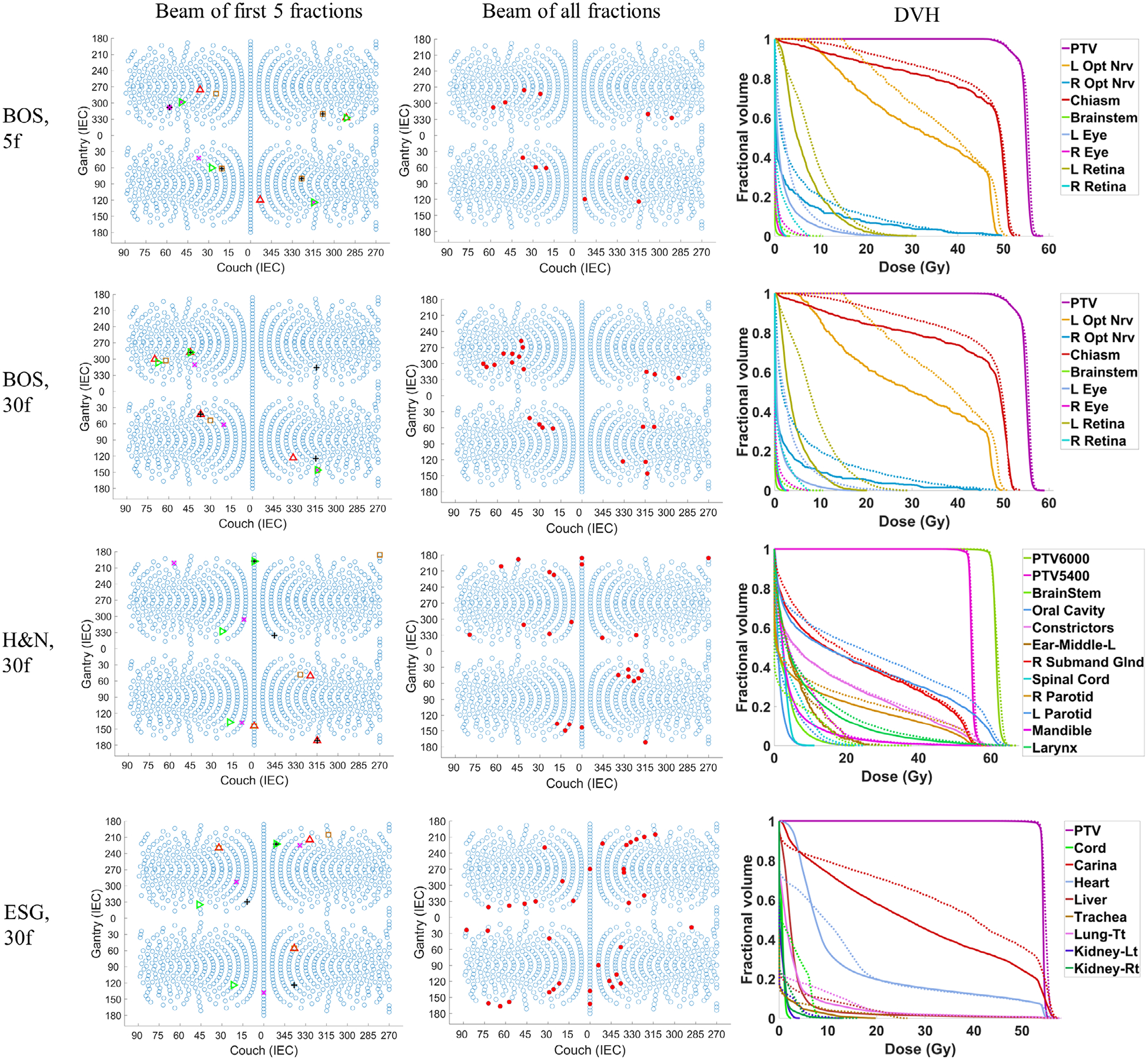
The beam angles of the first 5 fractions of the FVBOO plans (left), the beam angles of all fractions of the FVBOO plans (middle), and the DVH comparison of the 30f FVBOO plans (solid) with the FIBOO plan (dotted) for the three patients. The FVBOO plans have the similar number of beams per fraction as FIBOO. In the left column, the beams from the different fractions are shown in different color and symbols.
Fig. 2.
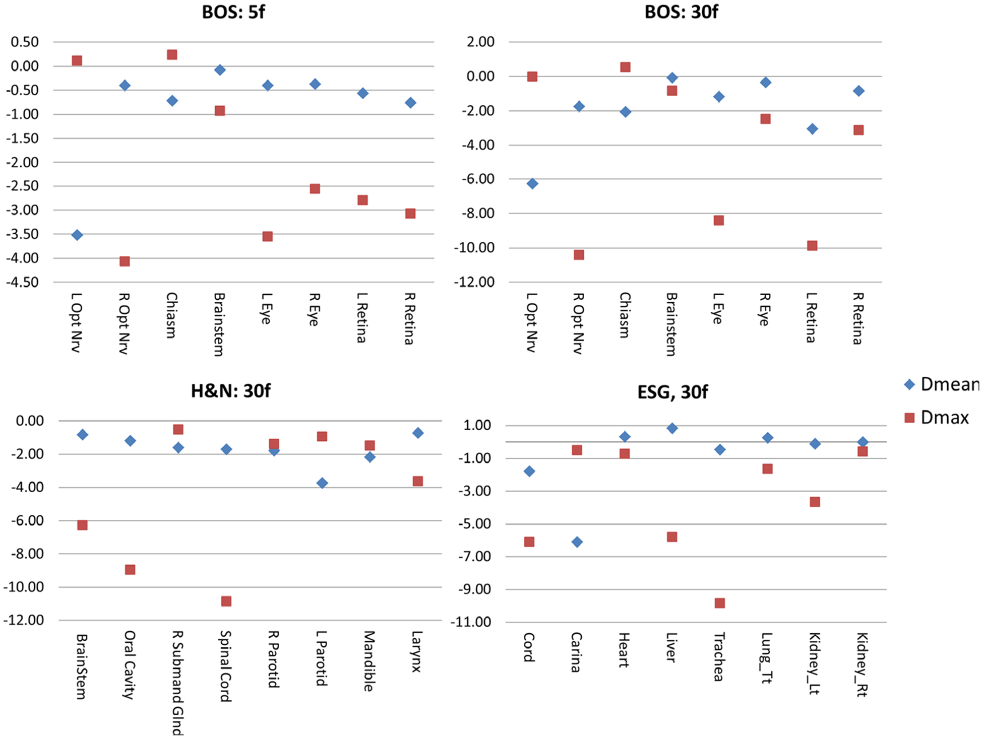
The difference of organs at risk Dmean (blue) and Dmax (red) in GyRBE of the fraction-variant beam orientation optimization plans from the fraction-invariant beam orientation optimization (FIBOO) plans. A negative value represents a reduction from the FIBOO plan, and a positive value represents an increase.
For the 5f setting of the BOS patient, the 3.8 b/f plan achieves better OARs sparing compared with the FIBOO plan using four beams. The average reduction of [Dmean, Dmax] of the 3.8 b/f plans from the FIBOO plans were [0.85, 2.08] GyRBE.
For the 30f setting, the FVBOO plans of each patient achieve superior OARs sparing compared with the FIBOO plan with a similar number of beams per fraction, with an average reduction of [Dmean, Dmax] of [1.87, 4.06] GyRBE. The maximal reduction to the Dmax for each patient is the right optical nerve (10.42 GyRBE) for the BOS patient, spinal cord (10.86 GyRBE) for the H&N patient and trachea (9.82 GyRBE) for the ESG patient.
The volumes of the patient body irradiated by 2, 5, 10, and 20 GyRBE are listed in Table III. As expected, with more beams being used, the FVBOO plans resulted in a larger volume being irradiated by the 2 GyRBE low dose. However, V5 is actually lower with FVBOO in the H&N and ESG cases.
Table III.
The V2, V5, V10, V20 GyRBE to the body in volume (cc).
| Case | Plan | fractions | V2 | V5 | V10 | V20 |
|---|---|---|---|---|---|---|
| BOS | FIBOO | 5,30 | 1165.9 | 438 | 343.2 | 189 |
| FVBOO | 5 | 909.5 | 639.5 | 370.9 | 156.5 | |
| 30 | 962.9 | 683.1 | 367.7 | 162.5 | ||
| HN | FIBOO | 30 | 3819.7 | 3359.4 | 2650.4 | 1672.2 |
| FVBOO | 30 | 4519.6 | 3315.6 | 2440.3 | 1641 | |
| ESG | FIBOO | 30 | 5501.3 | 4757.5 | 3702.3 | 1748.2 |
| FVBOO | 30 | 9782.9 | 4525.2 | 2358.6 | 1265.8 |
In addition to the cumulative doses, the dose distributions of individual fractions are presented. The boxplots comparing the fractional dose distribution and cumulative distribution for both PTVs and OARs are shown in Fig. 3. In Fig. 3(a), the difference of PTV HI (homogeneity index) and D95% at each fraction from cumulative values are presented. Consistent with our planning goal, despite varying beams, the PTV is covered by a homogeneous dose in individual fractions. The average difference of fractional D95% of PTV from cumulative D95% is −0.5% with a standard deviation of 0.3%. The average difference of fractional HI of PTV from cumulative D95% is −1.6% with a standard deviation of 0.3%.
Fig. 3.
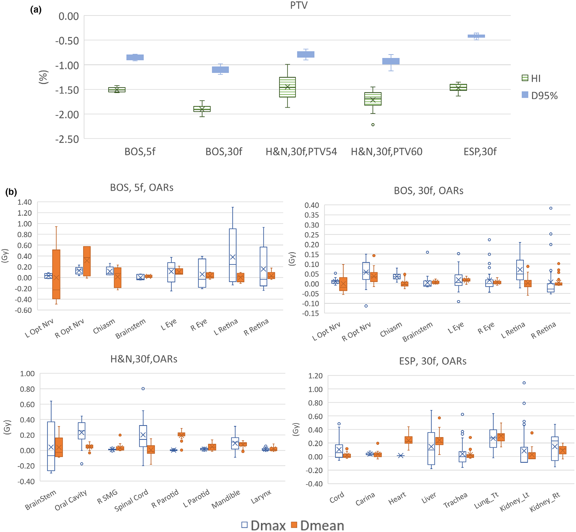
Boxplot comparing the fractional dose distribution and cumulative distribution (a) The difference of PTV HI and D95% at each fraction from cumulative dose. (b) The difference of OAR mean and max doses at each fraction from cumulative dose distribution. The cumulative OAR mean and max doses are re-scaled to the fractional dose level (divided by the number of fractions). A negative sign represents lower value in one fraction than cumulative value.
Figure 3(b) shows the difference of OAR Dmean and Dmax at each fraction from cumulative Dmean and Dmax. The cumulative OAR mean and max doses are rescaled to the fractional level (divided by the number of fractions) for easy comparison. From Fig. 3(b), the OARs doses vary with different fractions. The largest difference is the left retina of the BOS patient at 5f setting, with Dmax in one fraction 1.3 GyRBE higher than cumulative Dmax divided by number of fractions. But in 30f settings, the Dmean and Dmax difference for most OARs are smaller than 1 GyRBE.
3.C. Reduce the number of beams in FIBOO
For the BOS patient, the number of beams per fraction is further reduced from around 4 to around 1. The dose volume histogram (DVH) and dose wash comparison with a decreasing number of beams is shown in Fig. 4. For the 5f setting, while the 3.8 b/f plan achieves the best OARs sparing, with an average reduction of [Dmean, Dmax] from the FIBOO plans of [0.85, 2.08] GyRBE, the FVBOO plan with 3b/f achieves slightly better OARs sparing compared with the FIBOO, with an average reduction of [Dmean, Dmax] of [0.17, 1.45] GyRBE. The 1.8 b/f plan has worse OAR doses than the FIBOO plan, except the sparing to the right eye and right retina.
Fig. 4.
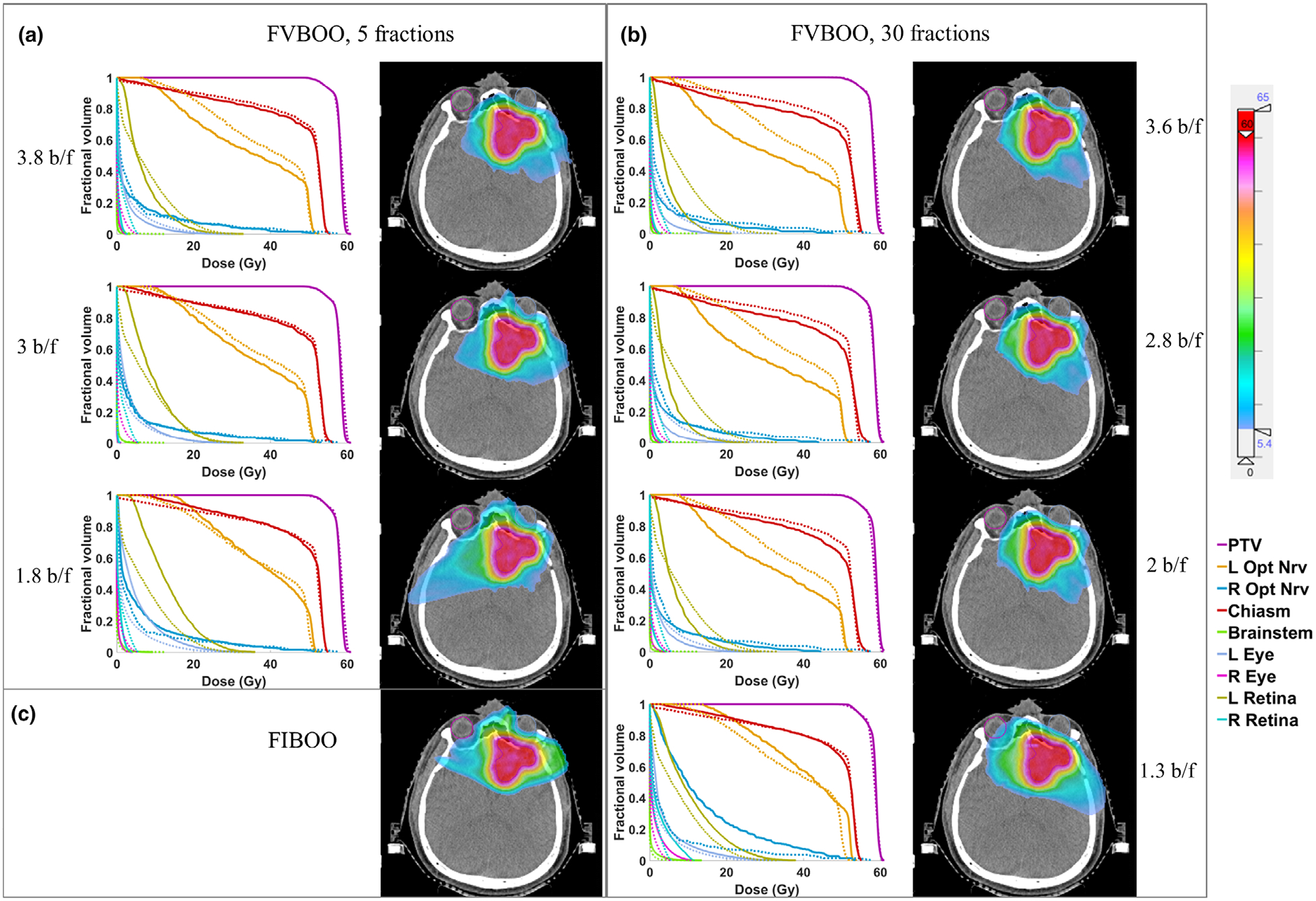
The DVH and dose colorwash using different number of beams for the base-of-skull patient. (a) The DVH comparison of the 5f fraction-variant beam orientation optimization (FVBOO) plans (solid) with the FIBOO plan (dotted), and the cumulative dose distribution of the 5f FVBOO plans. (b) The DVH comparison of the 30f FVBOO plans (solid) with the FIBOO plan (dotted), and cumulative dose distribution of the 30f FVBOO plans. (c) The dose colorwash of the FIBOO plan.
For the 30f setting, when further reducing the beams per fraction, to 2.8 and 2, the FVBOO plan still achieves better OARs sparing compared with the FIBOO plans with more beams, with an average reduction of [Dmean, Dmax] of [1.71, 4.10] GyRBE for the 2.8 b/f plan and [1.26, 3.17] GyRBE for the 2 b/f plan. The average beam number of 1.3 is too low for FVBOO to compete with FIBOO using four beams.
4. DISCUSSION
While traditional fractionated IMPT plans use fixed fields and fluence map to deliver the same dose distribution to the patient during the treatment sessions, this work describes a novel method to vary beam angles and fluence maps among different fractions. The fraction-variant beam orientation and fluence map are simultaneously obtained using an optimization framework integrating modified dose fidelity terms and a group sparsity term for beam selection. The FVBOO framework generates fractionated plans that allow the OAR doses to vary for superior cumulative sparing without compromising PTV dose homogeneity in individual fractions. Different from proton arc therapy relying on the proprietary hardware and control system, FVBOO can be delivered on all existing proton systems capable of IMPT.
Besides the ability to improve the dosimetry using a similar number of beams, FVBOO can be used to improve delivery efficiency using fewer beams per fraction without compromising dosimetry. For example, in the 5f scheme, a three-beam FVBOO plan performs comparably with a four-beam FIBOO plan. In the 30f scheme, a two-beam FVBOO plan better spares OARs than the four-beam FIBOO plan. Considering the slow gantry rotating speed and the fact that a beamline is usually shared among multiple gantry rooms, the use of fewer beams in a treatment fraction affords the reduction of treatment time and improvement in patient throughput.
In the current problem formulation, the fractional dose of PTV and the cumulative dose of OARs are considered and penalized. Under this condition, the OARs doses in each fraction are not strictly constrained but naturally limited by the dose to the PTV, as shown in Fig. 3(b). Penalizing the cumulative OAR doses is considered acceptable following the safe clinical practice of passive scattering proton therapy with alternating subsets of fields.22 On the other hand, it is also straightforward to constrain fractional OAR doses in the current framework by adding an OAR fractional dose penalization term in FVBOO.
A more rigorous approach, however, as pointed by Engelsman et al.,22 is to account for the biological effect of the normal tissues fraction-variant doses. Instead of penalizing cumulative or fractional physical doses, it may be more effective to optimize the total biological effective dose. Mathematically, the current FVBOO method can be adapted to penalize the cumulative OAR biological effect with available tissue repair parameters.
For the same reason, our FV approach is different from the spatiotemporal modulation proposed by Unkelbach et al23–25 and Gaddy et al26,27 that introduces a heterogeneous fractional tumor dose to improved overall biologically equivalent dose (BED). By maintaining the same uniform tumor dose throughout the treatment course, our method focuses on the physical dose, is robust to interfractional registration error, and may be more easily accepted by the current clinical practice.
The ability to select variant beams for the FVBOO method relied on the nonconvex L2,1/2-norm group sparsity. We derived the proximal function for the group sparsity term so (1) can be solved by FISTA, which is by far more efficient in this application than ADMM. FISTA originally assumes the function convexity.18 Nevertheless, we found that FISTA converged to a good solution even in the case of using the nonconvex L2,1/2-norm group sparsity penalty.4,17 In this particular case, we observed in the 30f plans, only 20 of 109 total selected beams are single-use. This is possibly due to the local minima and initialization condition, which currently use random initialization, and that the optimization is trapped in local minima. Besides the demonstrated dosimetric performance, further improvement may be possible by using a different initialization strategy. On the practical side, reusing the “good” beam angles can reduce the QA workload. The tradeoff between using more beams and using the best beams can be further explored.
FVBOO method would create a challenge in the measurement-based patient-specific qualify assurance (PSQA), which needs to be performed for individual fractions instead of the entire plan. However, the hurdle may be overcome by adopting calculation28–30 and treatment log file analysis31–33 based PSQA. Measurement-based QA can be accelerated via scripting and automated delivery. Note that unique beams only need to be delivered once. The individual fractions can be assembled in postprocessing.
Another challenge of FVBOO is its longer computational time. For the ESG case with a large PTV volume of 480cc, the FVBOO plan took about 10 h in comparison to the 30 min used by FIBOO planning. On the other hand, the extra computational time can be unsupervised after adopting the same planning parameters from the FIBOO plan.
In IMPT planning, robustness is an important factor to consider. Although uncertainties are not incorporated in the current FVBOO framework, we expect a similarity in the plan robustness like the proton arc therapy.11 Different beam orientation configurations spread out distal range uncertainties to a wider space, which minimizes the impact of uncertainties from individual beams. However, different from fraction-invariant treatments where the same beams are used in all fractions, random uncertainties of single-use beams may not be mitigated by fractionation. The combined effects of spreading out distal edges and the random uncertainties of individual beams may be patient specific and need to be carefully assessed in future work. In addition, we have proposed an integrated robust BOO framework for IMPT,15 which generates robust beam orientation and robust fluence map efficiently in a single step. Sensitivity regularization and heterogeneity weighting were added to the group sparsity-based BOO framework to encourage robustness. In future work, the fraction-variant idea and robust BOO will be combined to promote the robustness of FVBOO plans.
Similar to proton arc therapy, FVBOO improves the dose conformity and adjacent organ sparing at the cost of increased low dose bath to normal tissue, as shown by the increase V2 and V5. Therefore, the use of FVBOO has to consider individual clinical requirements to balance the need for high dose conformality (to spare adjacent OARs) and the need to minimize low-dose bath effects. Nevertheless, FVBOO offers an alternative option to the clinicians.
5. CONCLUSIONS
This work demonstrates a new IMPT optimization approach to vary beam angles during different treatment sessions. It provides a solution to use few beams per fraction but many more beams throughout the entire treatment to improve either the plan quality or treatment delivery efficiency.
ACKNOWLEDGMENT
This research is supported by NIH Grants Nos. R44CA183390, R43CA183390, R01CA188300 and R01CA230278.
Footnotes
CONFLICT OF INTEREST
The authors have no relevant conflict of interest to disclose.
REFERENCES
- 1.Lomax AJ, Böhringer T, Bolsi A, et al. Treatment planning and verification of proton therapy using spot scanning: initial experiences. Med Phys. 2004;31:3150–3157. [DOI] [PubMed] [Google Scholar]
- 2.Steneker M, Lomax A, Schneider U. Intensity modulated photon and proton therapy for the treatment of head and neck tumors. Radiother Oncol. 2006;80:263–267. [DOI] [PubMed] [Google Scholar]
- 3.Cao W, Lim GJ, Lee A, et al. Uncertainty incorporated beam angle optimization for IMPT treatment planning. Med Phys. 2012;39:5248–5256. [DOI] [PMC free article] [PubMed] [Google Scholar]
- 4.Gu W, O’Connor D, Nguyen D, et al. Integrated beam orientation and scanning-spot optimization in intensity-modulated proton therapy for brain and unilateral head and neck tumors. Med Phys. 2018;45:1338–1350. [DOI] [PMC free article] [PubMed] [Google Scholar]
- 5.Liu C, Bhangoo RS, Sio TT, et al. Dosimetric comparison of distal esophageal carcinoma plans for patients treated with small-spot intensity-modulated proton versus volumetric-modulated arc therapies. J Appl Clin Med Phys. 2019;20:15–27. [DOI] [PMC free article] [PubMed] [Google Scholar]
- 6.Li X, Liu G, Janssens G, et al. The first prototype of spot-scanning proton arc treatment delivery. Radiother Oncol. 2019;137:130–136. [DOI] [PubMed] [Google Scholar]
- 7.Ding X, Zhou J, Li X, et al. Improving dosimetric outcome for hippocampus and cochlea sparing whole brain radiotherapy using spot-scanning proton arc therapy. Acta Oncol (Madr). 2019;58:483–490. [DOI] [PubMed] [Google Scholar]
- 8.Liu C, Sio TT, Deng W, et al. Small-spot intensity-modulated proton therapy and volumetric-modulated arc therapies for patients with locally advanced non-small-cell lung cancer: a dosimetric comparative study. J Appl Clin Med Phys. 2018;19:140–148 [DOI] [PMC free article] [PubMed] [Google Scholar]
- 9.Li X, Kabolizadeh P, Yan D, et al. Improve dosimetric outcome in stage III non-small-cell lung cancer treatment using spot-scanning proton arc (SPArc) therapy. Radiat Oncol. 2018;13:1–9. [DOI] [PMC free article] [PubMed] [Google Scholar]
- 10.Ding X, Li X, Qin A, et al. Have we reached proton beam therapy dosimetric limitations?–A novel robust, delivery-efficient and continuous spot-scanning proton arc (SPArc) therapy is to improve the dosimetric outcome in treating prostate cancer. Acta Oncol (Madr). 2018;57:435–437. [DOI] [PubMed] [Google Scholar]
- 11.Ding X, Li X, Zhang JM, Kabolizadeh P, Stevens C, Yan D. Spot-scanning proton arc (SPArc) therapy: the first robust and delivery-efficient spot-scanning proton arc therapy. Int J Radiat Oncol Biol Phys. 2016;96:1107–1116. [DOI] [PubMed] [Google Scholar]
- 12.Rah JE, Kim GY, Oh DH, et al. A treatment planning study of proton arc therapy for para-aortic lymph node tumors: dosimetric evaluation of conventional proton therapy, proton arc therapy, and intensity modulated radiotherapy. Radiat Oncol. 2016;11:140. [DOI] [PMC free article] [PubMed] [Google Scholar]
- 13.Gu W, Neph R, Ruan D, et al. Robust beam orientation optimization for intensity-modulated proton therapy. Med Phys. 2019;46:3356–3370. [DOI] [PMC free article] [PubMed] [Google Scholar]
- 14.Gu W, Ruan D, Lyu Q, Zou W, Dong L, Sheng K. A novel energy layer optimization framework for spot-scanning proton arc therapy. Med Phys. 2020;47:2072–2084 [DOI] [PMC free article] [PubMed] [Google Scholar]
- 15.Gu W, Ruan D, O’Connor D, et al. Robust optimization for intensity-modulated proton therapy with soft spot sensitivity regularization. Med Phys. 2019;46:1408–1425. [DOI] [PMC free article] [PubMed] [Google Scholar]
- 16.Dink D, Langer MP, Rardin RL, Pekny JF, Reklaitis GV, Saka B. Intensity modulated radiation therapy with field rotation-a time-varying fractionation study. Health Care Manag Sci. 2012;15:138–154. [DOI] [PubMed] [Google Scholar]
- 17.O’Connor D, Yu V, Nguyen D, Ruan D, Sheng K. Fraction-variant beam orientation optimization for non-coplanar IMRT. Phys Med Biol. 2018;63:045015. [DOI] [PMC free article] [PubMed] [Google Scholar]
- 18.Beck A, Teboulle M. A Fast iterative shrinkage-thresholding algorithm for linear inverse problems. SIAM J Imaging Sci. 2009;2:183–202. [Google Scholar]
- 19.Cisternas E, Mairani A, Ziegenhein P, Jäkel O, Bangert M. matRad – a multi-modality open source 3D treatment planning toolkit In: IFMBE Proceedings. 2015;51:1608–1611. [Google Scholar]
- 20.Wieser HP, Cisternas E, Wahl N, et al. Development of the open-source dose calculation and optimization toolkit matRad. Med Phys. 2017;44: 2556–2568. [DOI] [PubMed] [Google Scholar]
- 21.Grégoire V, Mackie TR. State of the art on dose prescription, reporting and recording in Intensity-modulated radiation therapy (ICRU report. No. 83). Cancer/Radiotherapie. 2011;15:555–559. [DOI] [PubMed] [Google Scholar]
- 22.Engelsman M, Delaney TF, Hong TS. Proton radiotherapy: the biological effect of treating alternating subsets of fields for different treatment fractions. Int J Radiat Oncol Biol Phys. 2011;79: 616–622. [DOI] [PMC free article] [PubMed] [Google Scholar]
- 23.Unkelbach J, Zeng C, Engelsman M. Simultaneous optimization of dose distributions and fractionation schemes in particle radiotherapy. Med Phys. 2013;40:091702. [DOI] [PMC free article] [PubMed] [Google Scholar]
- 24.Unkelbach J, Papp D. The emergence of nonuniform spatiotemporal fractionation schemes within the standard BED model. Med Phys. 2015;42:2234–2241. [DOI] [PubMed] [Google Scholar]
- 25.Unkelbach J, Papp D, Gaddy MR, Andratschke N, Hong T, Guckenberger M. Spatiotemporal fractionation schemes for liver stereotactic body radiotherapy. Radiother Oncol. 2017;125:357–364. [DOI] [PMC free article] [PubMed] [Google Scholar]
- 26.Gaddy MR, Yildiz S, Unkelbach J, Papp D. Optimization of spatiotemporally fractionated radiotherapy treatments with bounds on the achievable benefit. Phys Med Biol. 2018;63:015036. [DOI] [PubMed] [Google Scholar]
- 27.Gaddy MR, Unkelbach J, Papp D. Robust spatiotemporal fractionation schemes in the presence of patient setup uncertainty. Med Phys. 2019; 46:1288–3000. [DOI] [PubMed] [Google Scholar]
- 28.MacKin D, Li Y, Taylor MB, et al. Improving spot-scanning proton therapy patient specific quality assurance with HPlusQA, a second-check dose calculation engine. Med Phys. 2013;40:121708. [DOI] [PubMed] [Google Scholar]
- 29.Zhu XR, Li Y, Mackin D, et al. Towards effective and efficient patient-specific quality assurance for spot scanning proton therapy. Cancers (Basel). 2015;7:631–647. [DOI] [PMC free article] [PubMed] [Google Scholar]
- 30.Meier G, Besson R, Nanz A, Safai S, Lomax AJ. Independent dose calculations for commissioning, quality assurance and dose reconstruction of PBS proton therapy. Phys Med Biol. 2015;60:2819–2836. [DOI] [PubMed] [Google Scholar]
- 31.Li H, Sahoo N, Poenisch F, et al. Use of treatment log files in spot scanning proton therapy as part of patient-specific quality assurance. Med Phys. 2013;40:021703. [DOI] [PMC free article] [PubMed] [Google Scholar]
- 32.Scandurra D, Albertini F, Van Der Meer R, et al. Assessing the quality of proton PBS treatment delivery using machine log files: Comprehensive analysis of clinical treatments delivered at PSI Gantry 2. Phys Med Biol. 2016;61:1171–1181. [DOI] [PubMed] [Google Scholar]
- 33.Belosi MF, van der Meer R, de Acilu G, et al. Treatment log files as a tool to identify treatment plan sensitivity to inaccuracies in scanned proton beam delivery. Radiother Oncol. 2017;125:514–519. [DOI] [PubMed] [Google Scholar]