Abstract
An arterial switch operation (ASO) is the standard treatment for infants and children born with D-loop transposition of the great arteries. During the ASO, the great vessels are transected from the native roots, switched and anastomosed with the opposite roots. This is accompanied by the relocation of the pulmonary artery anterior to the aorta by using the LeCompte maneuver and the translocation of coronary arteries to the neo-aorta. ASO has led to improved overall survival, and postoperative mortality is rare. Despite the improved outcomes, several postoperative sequelae may occur, and therefore patients require long-term follow-up. Computed tomography (CT) has emerged as a robust imaging modality in pre and postoperative evaluation of a variety of congenital heart disorders including ASO. Unlike echocardiography and cardiovascular magnetic resonance, CT is not hindered by a poor acoustic window, metallic devices or the need for sedation or general anesthesia. CT with advanced three-dimensional postprocessing techniques, high pitch scanning, wider detector system, electrocardiogram-dependent modulation and dose-reduction strategies is invaluable in assessing the postoperative complications after ASO.
Keywords: Arterial switch procedure, Atrial switch operation, Atrial switch repair, Jatene procedure, Transposition of great vessels
INTRODUCTION
Transposition of the great arteries (TGA) is the second most common cyanotic congenital heart defect. It is characterized by atrioventricular concordance and ventriculoarterial discordance. An arterial switch operation (ASO) is the standard treatment for TGA. It has improved the patient survival, and the majority of these patients are reaching adulthood.1) Although late mortality is rare, delayed complications involving the neo-aortic root, pulmonary arteries and reimplanted coronary arteries are commonly seen as causes of mortality. The various available imaging modalities for post-operative follow-up include echocardiography, computed tomography (CT), cardiovascular magnetic resonance (CMR), invasive angiography and nuclear scintigraphy. Each modality has its own strengths and weaknesses. Generally, echocardiography is the first imaging modality of choice, but it is incapable of adequately assessing key parameters in adults due to a restricted acoustic window.2) CMR, although it is the more robust imaging modality, is limited by higher cost, low availability, the need for sedation or general anesthesia, long acquisition times and image artifacts due to metallic devices (pacemakers, defibrillators, stents and occluder devices). CT has emerged as a great diagnostic tool. The latest advancements in CT technology, like high-pitch scanning, fast gantry rotation, wider detector systems, electrocardiogram (ECG) gating, automated tube voltage selection and tube current modulation have revolutionized the role of CT in the pre- and postoperative evaluation of congenital heart diseases. Specifically, it is not hindered by metallic devices, long acquisition times or the need for sedation. The aim of this essay is to review the post-operative complications of ASO and the role of CT in postoperative follow-up.
ARTERIAL SWITCH PROCEDURE
The surgical correction of TGA was first attempted in 1950 with an early form of ASO. At that time, the inability to successfully transfer coronary arteries from the aorta to neo-aorta led to poor outcomes. In the same decade Mustard and Senning developed multiple palliative strategies, ultimately leading to the atrial switch operation (AtrSO).3),4) AtrSO involved rerouting the superior vena cava and inferior vena cava flow to the mitral valve, and pulmonary venous blood to the tricuspid valve, by creating intra-atrial baffles. This technique resulted into favorable mid-term survival and was widely practiced from the 1960s to the 1980s. Although AtrSO resulted in anatomical correction, the physiological correction was still lacking. The systemic circulation was still dependent upon the right ventricle (RV). As a result, RV dysfunction and tricuspid regurgitation emerged as very common long-time complications. This led to the search for a more physiological procedure.
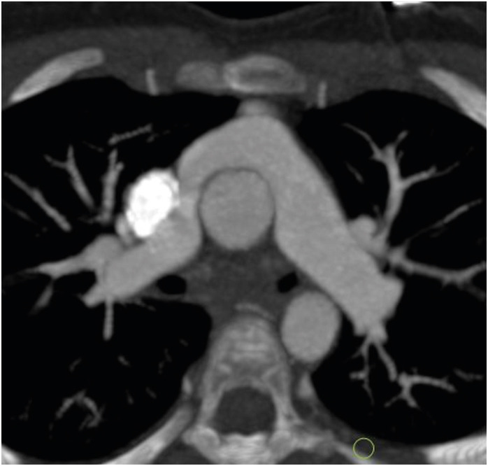
In 1975, Jatene et al.5) performed the first arterial switch operation. In this procedure, both the aorta and the pulmonary arteries are transacted from the native roots and switched to the opposite roots. The old aortic root becomes the neo-pulmonary root, and the old pulmonary root becomes the neo-aortic root. Coronary arteries are excised from the native aortic root with a small cuff of wall and implanted onto the neo-aortic root. During the translocation of the coronary arteries, the pattern of coronaries is kept the same as the original pattern to avoid any postoperative kink, stenosis or abnormal curvature. ASO restores both the anatomical as well as the physiological circulation. It was seen that the main cause of mortality in the early postoperative period was coronary abnormalities. In 1981, an additional technique called the LeCompte maneuver was added to the arterial switch, which involved the relocation of the pulmonary trunk anterior to the aorta (Figure 1). The aim of this procedure was to maximize the aortic length, thereby reducing the chances of coronary artery compression and kinking.6)
Figure 1. Axial maximum intensity projection CT angiography image of TGA following an ASO with the LeCompte maneuver. The branch pulmonary arteries bifurcate anterior to the ascending aorta and ‘drape over’ it. The great arteries are lying directly in antero-posterior relation and the right and left branch PA sizes are balanced.
ASO: arterial switch operation, CT: computed tomography, TGA: transposition of the great arteries.
ASO has become the standard treatment for patients with dextro-TGA. The overall survival of these patients has improved, and mortality is rare. Since the majority of the patients are reaching adulthood, the long-term complications of ASO are increasingly being recognized as sources of morbidity. The postoperative complications can be divided into early and late categories. Early postoperative complications include coronary artery kinking or stenosis, ventricular dysfunction, neo-aortic valve regurgitation, neo-pulmonary valve regurgitation, supravalvular pulmonary artery stenosis, supravalvular aortic stenosis, pulmonary hypertension and residual ventricular septal defect. Late postoperative complications include neo-aortic root dilatation, neo-aortic valve regurgitation, supra-aortic obstruction, supra-valvular pulmonary stenosis, branch pulmonary artery stenosis, subaortic obstruction, coronary artery stenosis or occlusion and pulmonary hypertension.7),8)
OVERVIEW OF THE MODALITIES
Diagnostic information can be attained by a variety of diagnostic tools like echocardiography, CT, CMR and invasive angiography. Each modality has its own strengths and weaknesses. The decision to choose any modality depends on the clinical question. Generally, echocardiography is the first line in diagnostic imaging. It is capable of providing the relevant and required information in infants and children. The main drawbacks of echocardiography are operator dependency and the inability to get a good acoustic window in older children and adults. CMR is a promising imaging modality in the pre and postoperative evaluation of a wide variety of congenital heart diseases. It is a reliable technique to assess great vessels, ventricular function, valve regurgitation and myocardial viability. It has been seen that despite the various surgeries and life-saving palliation in coronary heart disease, the RV may experience persistent pressure or volume overload. Additionally, there may be intrinsic RV myopathy or processes that result in RV dysfunction. This requires accurate and reproducible measurements of RV function. CMR is currently the gold standard for quantifying RV function because of its high level of spatial resolution, precise definition of complex anatomy and excellent reproducibility.9) However, CMR has many drawbacks including higher cost, low availability, the need for sedation or general anesthesia and long acquisition time. Besides this, motion-free imaging and high spatial resolution is always challenging in infants and small children. Although the recent guidelines recommend that magnetic resonance imaging (MRI) can be performed in patients with implanted devices (MRI conditional or not) as long as the safety conditions are met, the significant artifacts generated due to devices, often due to packing boxes implanted in chest walls, make the study non-diagnostic.10) Many TGA patients have implanted devices such as vascular stents, occlusion coils and septal occluders, which may cause artifacts, limiting the utility of CMR. Catheter angiography is an invasive procedure and is associated with the risk of catheter-related complications.
Multidetector CT imaging has been revolutionized in the past decade. The current generation CT scanners provide high quality images with good temporal and spatial resolution. The widespread use of CT was previously limited due to radiation concerns, but recent technical advancements including high-pitch scanning, fast gantry rotation and wider detector systems have resulted in significant reductions in radiation doses. Patients with ventricular dysfunction and atrial arrythmias may have defibrillators and pacemakers in place. Cardiac CT is extremely useful under these conditions. Furthermore, cardiac CT is an ideal modality for the detailed assessment of reimplanted coronary arteries for narrowing, kinking, ostial stenosis and atherosclerotic disease.11) It can also demonstrate the relationship of coronaries to the sternum before a redo sternotomy. A retrospective ECG-gated scan can provide cardiac functional analysis. Another area of exploration for CT in congenital heart disease is 3-dimensional (3D) printed models. Sometimes it is difficult to comprehend the visualization of cardiac structures on 2D. CT data can be used to create patient-specific 3D heart models, which can improve spatial visualization, assist in preoperative planning and serve as useful tools in medical education and training.12)
The main limitations of CT are the limited availability of recent generation scanners, the requirement of trained personnel, the need for intravenous access, iodinated contrast administration and ionizing radiation.
GENERAL CONSIDERATIONs
The protocol optimization for cardiac imaging is quite challenging in pediatric patients. This is due to the complexity of congenital diseases, high heart and respiratory rates, non-cooperative patients and the requirement for stringent dose reduction. The advanced scanning options like high pitch scanning, automated tube voltage and current selection, ECG gating and iterative reconstruction can beat these challenges.
Patient positioning is the important part of scanning. Any off-center positioning may lead to an increase in the dose or degradation of image quality. Poor positioning of arms and electrodes leads to streak artifacts. It is preferred to place the electrodes on the arms or upper abdomen. MRI-compatible carbon ECG patches generate less artifacts and are therefore a good alternative.
The advent of third-generation dual source CT (DSCT) scanners has made it possible to scan non-cooperative patients without anesthesia due to the higher scan speed and improved temporal resolution (75 ms for second-generation DSCT and 66 ms for third-generation DSCT). Despite the high heart rates in children (around 120 beats per minute), the high pitch mode provides diagnostic images in most of the scans.13)
As per the Society of Cardiac Computed Tomography (SCCT) guidelines, the volume of IV contrast should be calculated from body weight (1–2 mL/kg). The combined volume of contrast and saline flush should be maintained at 2–3 mL/kg, which is well tolerated without any hemodynamic consequences. The general guidelines for the flow rates of contrast and saline are 0.3–0.8 mL/sec for 0.5–5 kg of weight, 0.7–1.2 mL/sec for 5–14 kg, 1.2–2 mL/sec for 15–24 kg, 2–3 mL/sec for 25–34 kg and 3–4 mL/sec for 35–44 kg. The bolus tracking method (automatic or manual) is used to trigger the scan in the pediatric population. In the automatic bolus tracking method, the region of interest (ROI) is placed in the cardiac chambers (RV, left ventricle [LV] or left atrium [LA]) or vessels (the internal jugular vein in the patients with a Fontan operation to target the second circulation of the contrast agent) depending upon the clinical indication. A triggering threshold between 100 and 150 HU is selected with a scan delay of 2–5 seconds, depending on the CT model. There are several issues with automatic bolus tracking in children, the most important one being the movements of the patient during the bolus measurement, which can cause the scan to start too early or too late. This problem can be solved by manual triggering. In this method, the monitoring sequence is placed at mid-heart level to allow the simultaneous visualization of the cardiac chambers and descending aorta. The ROI is placed outside the body. The scan is initiated manually when the contrast is seen in all four cardiac chambers and the descending aorta. Image acquisition must be triggered prior to optimal opacification to account for the scan delay, which can be as long as 4 seconds in the highest pitch scan mode.
There are different types of contrast injection protocols. A biphasic injection protocol (contrast followed by saline) is used for pulmonary or systemic angiography. The saline chase flushes the contrast from RV, preventing streak artifacts, but results in very poor opacification of the RV. Therefore, this protocol is not good for evaluating RV or biventricular pathology. A biventricular or triphasic protocol is commonly used for the simultaneous assessment of both ventricles. There are 2 methods of achieving biventricular opacification. The first method is to give half the contrast at the usual arterial rate for patient size, and the remainder at a slower rate, followed by a saline flush. The second method is to keep the injection rate constant and administer a contrast: saline mix (e.g., 30:70 to 50:50 mix) for the second phase of the contrast bolus. Either method will result in biventricular opacification during image acquisition. This protocol is useful in patients with tetralogy of Fallot or after the ASO, which requires evaluation of both the right and left heart structures.13),14)
In general, pediatric patients can be scanned without ECG gating, although the image quality is inferior to those obtained with ECG gating. ECG gating is required for functional evaluation and for the evaluation of structures prone to cardiac motion artifacts (the aortic root, coronary arteries and intracardiac anatomy). The evaluation of the pulmonary arteries, aortopulmonary collaterals and airway do not require gating. Since assessment of coronaries and the aortic root are the key components of postoperative imaging, almost all the follow-up patients for ASO require ECG-gated scans. The gating could be prospective (the X-ray beam is turned on for only a short portion of diastole, and it is turned off during the rest of the R-R cycle) or retrospective (the X-ray beam is turned on throughout the R-R interval). A prospective ECG-triggered protocol provides motion-free images with lower doses in comparison to retrospective ECG-triggered acquisition. Studies have demonstrated that that radiation dose can be reduced up to 1–4 mSv without affecting the image quality. However, the prospective triggering mode provides a limited number of cardiac phases for image reconstruction. This is especially important if the heart rate is high. When the heart rate exceeds the recommended threshold for prospective ECG gating, an additional tube-on time, also called padding, is used. Padding refers to the time that the X-ray beam is on beyond the minimum time required to acquire an image of the heart at a single point in the middle of diastole, which is usually 100 ms. The duration of padding is in the range of 0–200 ms and is added to both sides of the center of the acquisition. A padding of 0 corresponds to a window of 100 ms of scanning time, and a padding of 100 corresponds to a window of 200 ms of scanning time. Padding is generally used when the heart rate is more than 65 bpm or when there is apparent heart rate variability (heart rate variation is more than 10 bpm).15)
The duration of padding determines the number of cardiac phases available for reconstruction. Increasing the duration of padding offers more phases for reconstruction at the cost of increased dose, while reduced padding results in fewer available phases with significant dose reduction.16) The high temporal resolution offered by dual source scanners waives the need for retrospective protocols, which are dose intensive. The only indication of retrospective ECG gating is a challengingly irregular heart rate, where dynamic information (valvular or ventricular function) is also required. A low radiation dose can be achieved with retrospective ECG gating with the use of ‘MinDose’ mode, where the tube current outside the predefined window is reduced to 4% of the prescribed value instead of 20%.17)
CT acquisition starts by obtaining a topogram. The dose of the topogram is adjusted according to the patient's age and weight. Generally, it is done by reducing the voltage from 100 to 80 kVp. The topogram, besides acting as a means to determine the scan range, also helps in assessing the patient's size and shape. Based on the attenuation profile of the scout scan, the specially designed kV Assist tool automatically selects the optimum tube potential. ECG-based tube current modulation is another technique for dose reduction. The full dose of tube current is limited to a predefined window and reduced outside the window.13)
SCAN PROTOCOL
Imaging was performed on a dual-source 128 (2×64)-slice CT machine. The intravenous access (20–24 gauge) was achieved in the right arm. The ECG electrodes were placed on the arms or upper abdomen. As there is potential for biventricle pathology, a biventricular injection protocol was used to opacify both ventricles simultaneously during a single acquisition. Non-ionic iodinated contrast (350 mg/mL) was given intravenously by a dual-head power injector followed by a saline chase. The rate of injection was dependent upon patient weight and intravenous cannula, but in the majority of the patients, it was between 1.2 and 3 mL/sec. Manual bolus tracking was performed. The monitoring sequence was placed at mid-heart to allow the simultaneous visualization of the cardiac chambers and descending aorta. The ROI was placed outside the body, and the scan was initiated after the visualization of contrast in the cardiac chambers. The scan delay time was between 2–5 seconds. Prospective or retrospective ECG gating was performed depending upon the clinical question. The scan range was selected to include the cardiac silhouette and branch pulmonary arteries. A delayed non-gated venous phase was acquired if there was need for venous evaluation. The reconstruction was done with an iterative technique.
APPROACH TO IMAGING
The major points of concern in imaging after ASO are the relationship of the great vessels, the integrity of the reimplanted coronaries, neo-aortic root dilatation, pulmonary artery stenosis, aortopulmonary collaterals, ventricular functions and bronchial compression.
GREAT VESSEL RELATIONSHIP
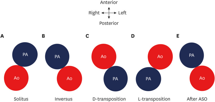
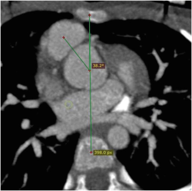
The great vessel relationship is visualized in axial sections at their ventricular origin. There are four different kinds of possible relationships depending upon the positions of the aorta and pulmonary artery. This could be a solitus relationship (the aortic valve is posterior and to the right of the pulmonary artery), an inversus relationship (the aortic valve is posterior and to the left of the pulmonary artery), a complete or d-transposition (the aortic valve is anterior and to the right of the pulmonary valve) or congenitally corrected or l-transposition (the aortic valve is anterior and to the left of the pulmonary valve) (Figure 2). In TGA, the great vessel relationship may vary from anterior posterior to side-by-side. The great vessel angle is measured by drawing two lines, one connecting the middle of the sternum and vertebra and the other connecting the middle of the aortic and pulmonary valve in a short axis (Figure 3). The mean value of this angle after arterial switch is 16 degrees, with a range of −36 to 48 degrees.18)
Figure 2. Diagram showing the possible relationships between the aorta and pulmonary arteries. (A) Solitus relationship; the aortic valve is posterior and to the right of the PA. (B) Inversus relationship; the aortic valve is posterior and to the left of the pulmonary valve. (C) Complete or d-transposition; the aortic valve is anterior and to the right of the pulmonary valve. (D) Congenitally-corrected or l-transposition; the aortic valve is anterior and to the left of the pulmonary valve. (E) ASO; the aortic valve is posterior and to the left of the pulmonary valve.
Ao: neo-aorta root, PA: pulmonary artery, ASO: arterial switch operation.
Figure 3. Axial maximum intensity projection CT angiography image showing normal great vessel configuration in a TGA patient after ASO. The great vessel angle is measured between the line connecting the middle of the sternum and vertebra and the line connecting the middle of the aortic and pulmonary valves along the short axis.
ASO: arterial switch operation, CT: computed tomography, TGA: transposition of the great arteries.
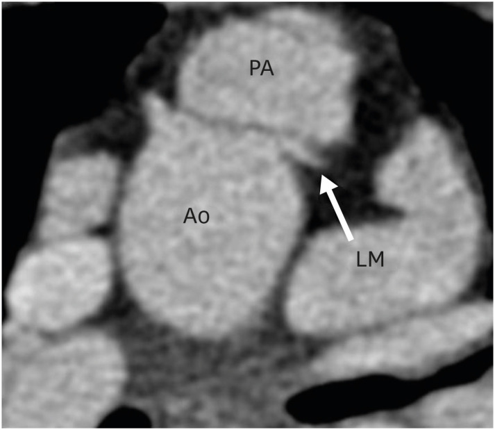
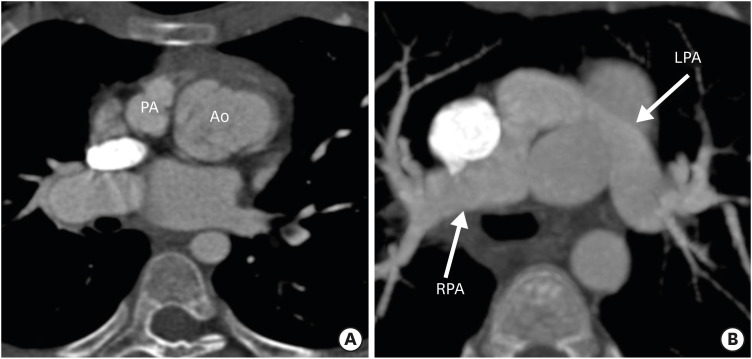
This angle has both pre- and post-operative significance. In vitro studies have demonstrated that a tension- or torsion-free repair of TGA is possible if the great vessel roots are arranged anterior-posteriorly or oriented up to a 35-degree angle.19) Therefore, the configuration of great vessels or the great vessel angle can predict the outcome of ASO, as far as the tension-free repair is concerned. This angle is equally important in post-operative follow-up. If this angle is too acute, i.e., the neo-pulmonary root is anteriorly placed over the neo-aortic root, it may compress the left main artery ostium, especially if the ostium is present between the 12 to 1 o′clock positions (Figure 4).20) Similarly, if the angle is very obtuse, i.e., the neo-pulmonary root is located more rightwards, it may cause excessive stretching of the left pulmonary artery (LPA) around the aorta, leading to potential stenosis (Figure 5).21)
Figure 4. Axial maximum intensity projection CT angiography image showing abnormal great vessel configuration in TGA patient after ASO. The pulmonary artery is directly placed anteriorly over the aorta, leading to the compression of the left coronary artery at the origin.
Ao: neo-aorta root, ASO: arterial switch operation, CT: computed tomography, LM: left main coronary artery, PA: pulmonary artery, TGA: transposition of the great arteries.
Figure 5. Axial maximum intensity projection CT angiography images showing abnormal great vessel configuration in TGA patient after ASO. (A) Image showing extreme rightward deviation of the neo-pulmonary root with respect to the aorta. (B) Image showing stretching of the LPA around the aorta in the same patient. The LPA is narrower in diameter as compared to right. The excessive rightward relation of the neo-pulmonary root leads to stretching of the LPA, which predisposes the patient to LPA stenosis.
Ao: neo-aorta root, ASO: arterial switch operation, CT: computed tomography, LPA: left pulmonary artery, PA: pulmonary artery, RPA: right pulmonary artery, TGA: transposition of the great arteries.
CORONARY COMPLICATIONs
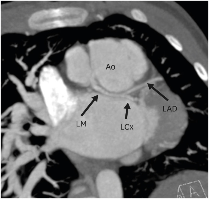
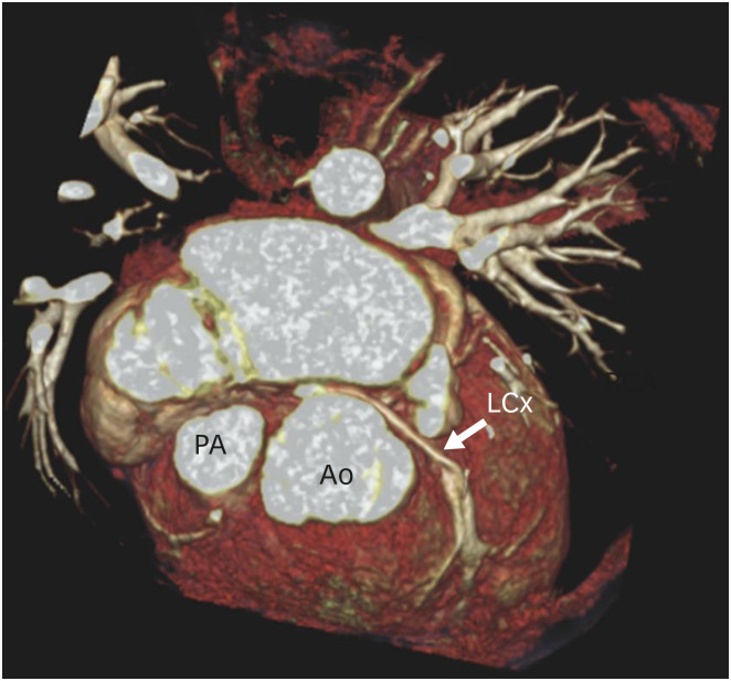
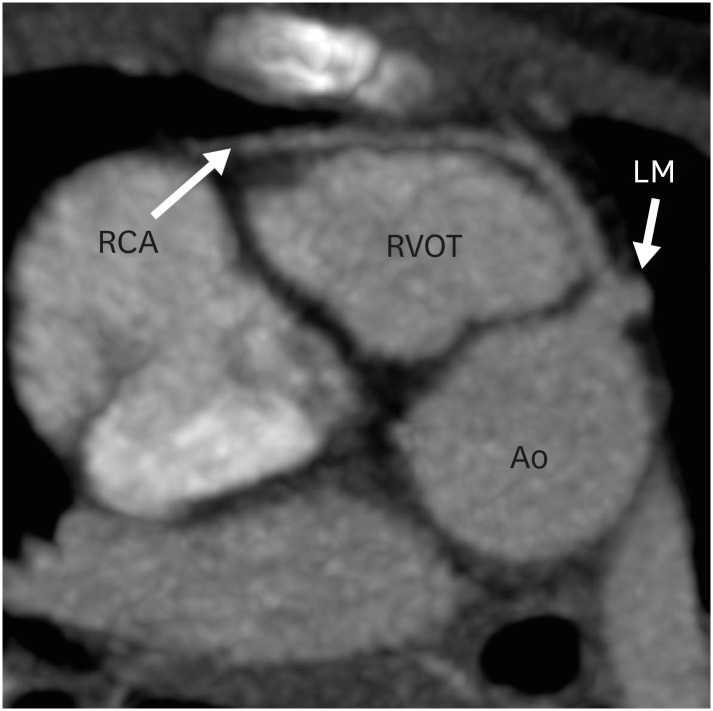
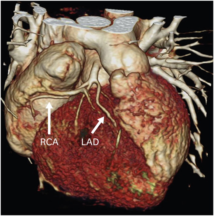
There is a high frequency of coronary anomalies in patients with TGA. The successful transfer of coronaries is a crucial step in ASO. The complex coronary patterns present surgical challenges requiring multiple modifications, depending on the relationship between the targeted sinus and the location of coronary artery reimplantation. During surgical transplantation, the pattern of coronaries is kept close to the original pattern to avoid stenosis or kinking. However, the surgically created patterns may undergo significant changes with physical growth and development. These changes may take the form of unfavorable and potentially dangerous features like proximal acute angulation, ostial stenosis, kinking, extrinsic compression, interarterial course and coronary fistulas to the pulmonary arteries (Figures 6-9).
Figure 6. Axial maximum intensity projection CT angiography image showing coronary abnormality in a TGA patient after ASO. The LM is seen arising from the right coronary cusp of the neo-aortic root and divides into left anterior descending and LCx after a short retro-aortic course.
Ao: neo-aortic root, ASO: arterial switch operation, LAD: left anterior descending artery, LCx: left circumflex artery, LM: left main trunk, TGA: transposition of the great arteries.
Figure 9. Three-dimensional volume rendering technique reconstruction image showing coronary abnormality in a TGA patient after ASO. The LCx is seen arising from the non-coronary sinus and shows a retro-aortic course before entering into the left atrioventricular groove.
Ao: neo-aortic root, ASO: arterial switch operation, LCx: left circumflex artery, PA: pulmonary artery, TGA: transposition of the great arteries.
Figure 7. Axial maximum intensity projection CT angiography image showing coronary abnormality in a TGA patient after ASO. The right coronary artery is seen arising from the LM and coursing anterior to the RVOT before entering into the right atrioventricular groove.
Ao: neo-aortic root, ASO: arterial switch operation, CT: computed tomography, LM: left main trunk, RCA: right coronary artery, RVOT: right ventricular outflow tract, TGA: transposition of the great arteries.
Figure 8. Three-dimensional volume rendering technique reconstruction image showing coronary abnormality in a TGA patient after ASO. There is a common origin of the RCA and LAD.
ASO: arterial switch operation, LAD: left anterior descending artery, RCA: right coronary artery, TGA: transposition of the great arteries.
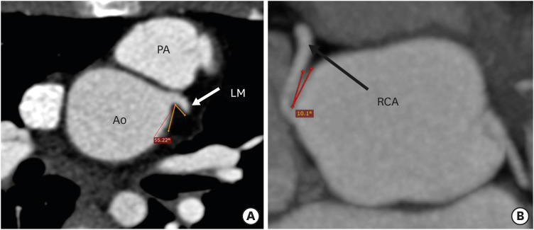
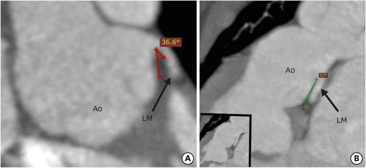
CT angiography allows detailed evaluation of the origins, courses and branching patterns of the coronary arteries. CT angiography allows measurement of the branching angle of coronaries to evaluate the ostial angulation in axial and coronal planes. The branching angle is calculated by drawing two lines in a tangential manner to the inner lumen of the proximal coronary artery and the aortic sinus (Figures 10 and 11).17) Studies have shown that more than 50% stenosis, an acute branching angle (< 30°) and inter-arterial course are associated with adverse cardiac events after ASO.22) As a significant percentage of patients with TGA are reaching adulthood after ASO, the identification of a high-risk group is essential to predict the future coronary events and help us to identify candidates needing competitive sports restrictions and lifestyle modifications.
Figure 10. Axial maximum intensity projection CT angiography image showing the branching angle of the coronary artery in the short axis in a TGA patient after ASO. (A) Image showing the normal branching angle of the left coronary artery along the short axis. Lines are drawn tangential to the inner lumen of the aortic sinus and the proximal part of the LM. (B) Image showing a very acute branching angle of the RCA in the short axis.
Ao: neo-aortic root, ASO: arterial switch operation, CT: computed tomography, LM: left main trunk, PA: pulmonary artery, RCA: right coronary artery, TGA: transposition of the great arteries.
Figure 11. Coronal maximum intensity projection CT angiography image showing the branching angle of the coronary artery in the long axis in a TGA patient after ASO. (A) Image showing normal branching angle of the left coronary artery in the long axis. Lines are drawn tangential to the inner lumens of the aortic sinus and LM. (B) Image showing a very acute branching angle of the LM in the long axis.
Ao: neo-aortic root, ASO: arterial switch operation, LM: left main trunk, TGA: transposition of the great arteries.
NEO-AORTIC ROOT DILATATION
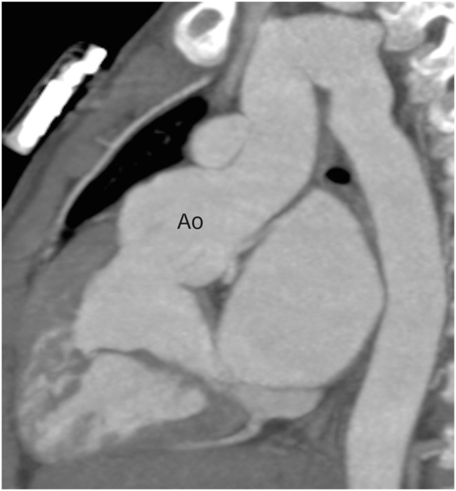
Progressive aortic root dilatation is another common late finding after ASO (Figure 12). The commonly proposed risk factors for neo-aortic dilatation include the presence of a ventricular septal defect, old age at the time of ASO, previous pulmonary artery banding, LeCompte maneuver, bicuspid aortic valve, perioperative mild neo-aortic regurgitation, acute aortic angles and a higher neo-aortic root/ascending aorta ratio. The vascular compromise to the neo-aortic root following the surgery is also a proposed factor. Transection of the aorta leads to the disruption of the vasa vasorum supplying the aortic root. It has been demonstrated that after the interruption of vasa vasorum, there is significant change in the morphology of collagen and elastin fibers, leading to increased aortic stiffness, which ultimately results into interlaminar shear stresses and hence aortic dilatation.23)
Figure 12. Sagittal maximum intensity projection CT angiography image in TGA patient after ASO, showing aortic root dilatation.
Ao: neo-aortic root, ASO: arterial switch operation, CT: computed tomography, TGA: transposition of the great arteries.
The rate of increase in the aortic root diameter in a healthy population is 0.08 mm/year, whereas a high rate of 0.63 mm/year has been reported in individuals after ASO.24),25) The Z-scores of the neo-aortic roots are used to follow up with these patients. A Z-score is a pragmatic alternative to the raw aortic root size commonly used in adults. It includes body surface area (BSA) in determining whether an aorta is within normal size limits. This allows us to determine whether true pathology exists, which can be challenging in growing children. There are number of web-based calculation tools for Z-score calculation. A dilated aortic root is defined as a Z-score ≥ 2.0, which corresponds with a diameter ≥ 2.0 standard deviation above normal.
A dilated neo-aortic root is often associated with neoaortic root regurgitation, although severe regurgitation is a rare finding. Similarly, no cases of aortic rupture or dissection have been reported after ASO, but in several reoperated patients, the anterior wall of the dilated aorta appeared fragile and paper-thin. CMR is the gold standard for assessing neo-aortic root dilatation and quantification of neo-aortic valve regurgitation. CT angiography also provides high resolution imaging of the aortic and neo-aortic roots and is the best alternative for prosthetic valve evaluation (stenosis, calcification, stenosis, leaflet immobility, paravalvular leak and valve vegetation).
PULMONARY ARTERY STENOSIS
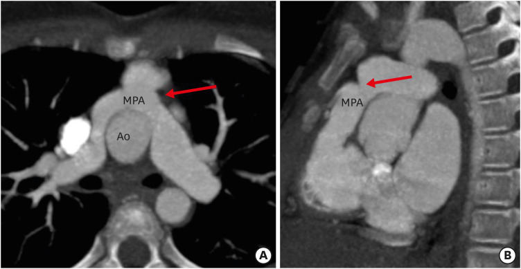
Pulmonary artery stenosis is a recognized complication after ASO. It is seen in two-thirds of patients and is the most common cause of intervention. It can involve both the central and the branch pulmonary arteries. The stenosis of the central pulmonary artery depends upon the surgical technique; the chances are higher with direct anastomosis in comparison to patch reconstruction (Figure 13). Among the branch pulmonary arteries, LPA stenosis is 1.5 times common than that of the right pulmonary artery (RPA). The stenosis of branch pulmonary arteries is related to their stretched course over the dilated aortic root. It has been proposed that a more rightwards position of the aortic root leads to stretching of the LPA over it, which predisposes it for potential stenosis.21),26) Systolic compression from an expanding aorta is also a contributing factor. CT angiography can demonstrate the location, length and severity of pulmonary stenosis. This is important, particularly in follow-up cases after angioplasty, where CMR is contraindicated (Figure 14).
Figure 13. (A) Axial and (B) sagittal maximum intensity projection CT angiography images in a TGA patient after ASO showing focal stenosis of the main pulmonary artery (red arrow).
Ao: neo-aortic root, ASO: arterial switch operation, CT: computed tomography, MPA: main pulmonary artery, TGA: transposition of the great arteries.
Figure 14. Axial contrast enhanced CT angiography image in a patient of TGA after ASO showing a stent in the LPA. Patient had LPA stenosis, and angioplasty was performed to relieve the stenosis.
ASO: arterial switch operation, CT: computed tomography, LPA: left pulmonary artery, TGA: transposition of the great arteries.
VENTRICULAR FUNCTION ASSESSMENT
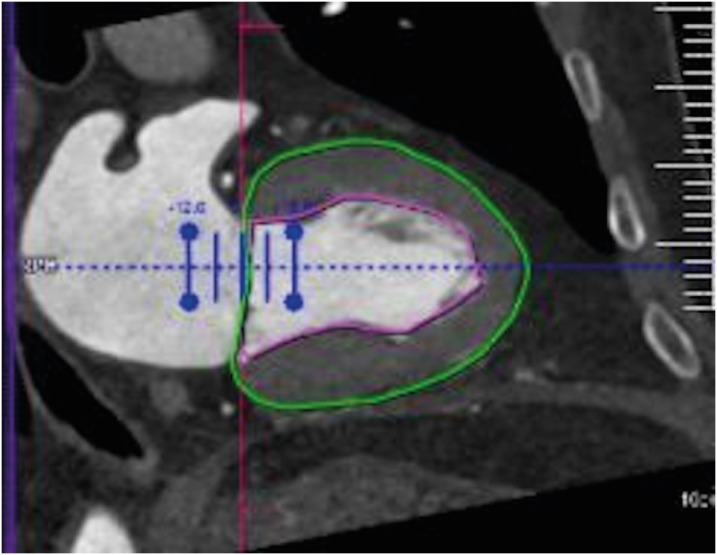
The assessment of ventricular function is an important component of evaluation after ASO. LV dysfunction is common in the early postoperative period. While the global LV dysfunction is related to myocardial stunning, the regional dysfunction heralds coronary artery ischemia. Similarly, RV dysfunction is common in the late postoperative period, the possible etiologies for which include problems with the right coronary artery, pulmonary artery stenosis and persistent pulmonary hypertension. Echocardiography is the first-line imaging modality. CMR is the gold standard for volumetry but is often contraindicated in patients with metallic implants like defibrillators and pacemakers and patients with severe claustrophobia. Additionally, patients with severe ventricular dysfunction may not be able to hold their breath or lie in a supine position for long periods. CT angiography is a problem-solving tool in this situation. It can provide both structural and functional information, particularly in regard to coronary arteries, cardiac valves, the sizes of cardiac chambers and myocardial performance (Figure 15). When compared with CMR as a reference standard, CT has shown accurate and reliable results for ventricular functional analysis.27)
Figure 15. Image showing an example of LV function data obtained from the patient at end-systole phase using CT. Vertical long-axis reformations of the LV with endocardial (pink) and epicardial (green) contours.
CT: computed tomography, LV: left ventricle.
MAJOR AORTOPULMONARY COLLATERALs
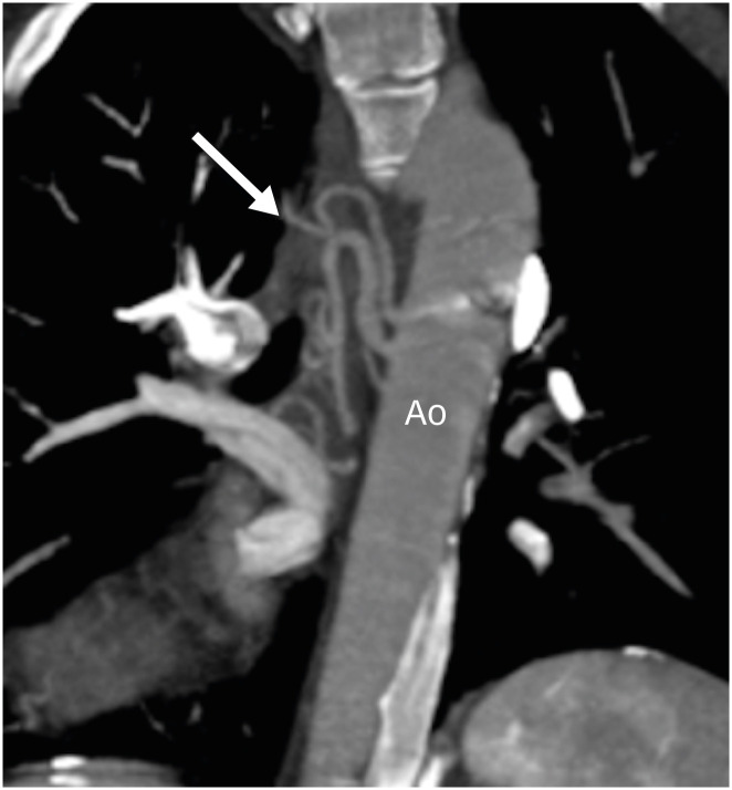
Major aortopulmonary collaterals (MAPCAs) are rarely seen in association with TGA. Many of these collaterals are small and remain clinically silent, but they might sometimes be large enough to cause systemic hypoxemia, left ventricular and respiratory failure, pulmonary overperfusion and massive airway bleeding. These are rarely detected before surgical repair even by aortic angiography, which could be due to ductal steal or pulmonary hypoxemia-induced vasoconstriction. They may cause difficulty in coronary transfer during ASO. It has also been documented that large MAPCAs may complicate the early postoperative course.28) Large MAPCAs are known to cause massive airway bleeding, pulmonary overperfusion and systemic hypoxemia as well as combined LV and respiratory failure after corrective surgery. These are commonly called “hemodynamically relevant MAPCAs” and are found in 15% of cases of TGA.29) CT angiography can accurately characterize the origin and course of MAPCAs (Figure 16). In addition, the complications of MAPCAs like massive airway bleeding can also be assessed in same sitting.
Figure 16. Coronal maximum intensity projection CT angiography image in a TGA patient after ASO showing aortopulmonary collaterals (arrow) supplying right pulmonary circulation.
Ao: neo-aorta root, ASO: arterial switch operation, CT: computed tomography, TGA: transposition of the great arteries.
BRONCHIAL COMPRESSION
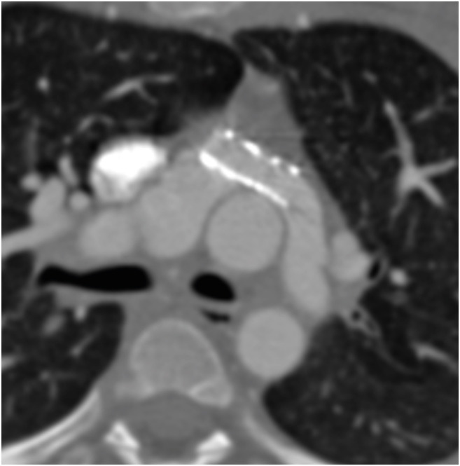
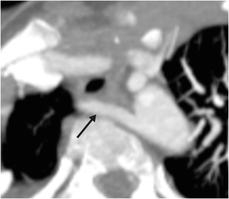
Bronchial compression is a very uncommon complication associated with ASO. It usually involves the left main bronchus, which gets compressed between the neo-aorta and the descending aorta. The low-lying neoaortic anastomotic line is a predisposing factor. According to Poiseuille's law, airway pressure is inversely proportional to the bronchial radius to the fourth power. Therefore, a small reduction in the radius of the airway may lead to significant clinical impact. It is essential to differentiate extrinsic bronchial compression from congenital stenosis, as the treatment options are different for both: i.e., aortopexy or left main bronchus liberalization in extrinsic compression and dilatation in congenital stenosis. CT is an excellent modality for demonstrating any airway compression (Figure 17). It can differentiate the intrinsic and extrinsic causes of bronchial narrowing. Moreover, CT can detect any associated lung parenchymal changes like air trapping or atelectasis.30)
Figure 17. Axial contrast enhanced CT angiography image in a TGA patient after ASO showing compression of the left main bronchus between the ascending aorta and the spine. Note the subtle hypoattenuation of the left lung as compared to the right, likely due to air trapping.
Ao: neo-aorta root, ASO: arterial switch operation, CT: computed tomography, TGA: transposition of the great arteries.
MISCELLANEOUS
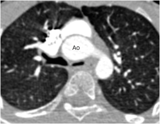
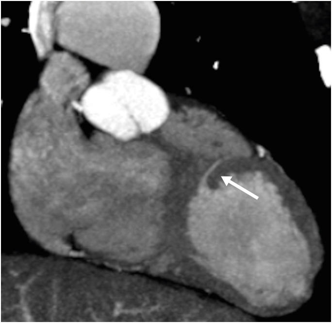
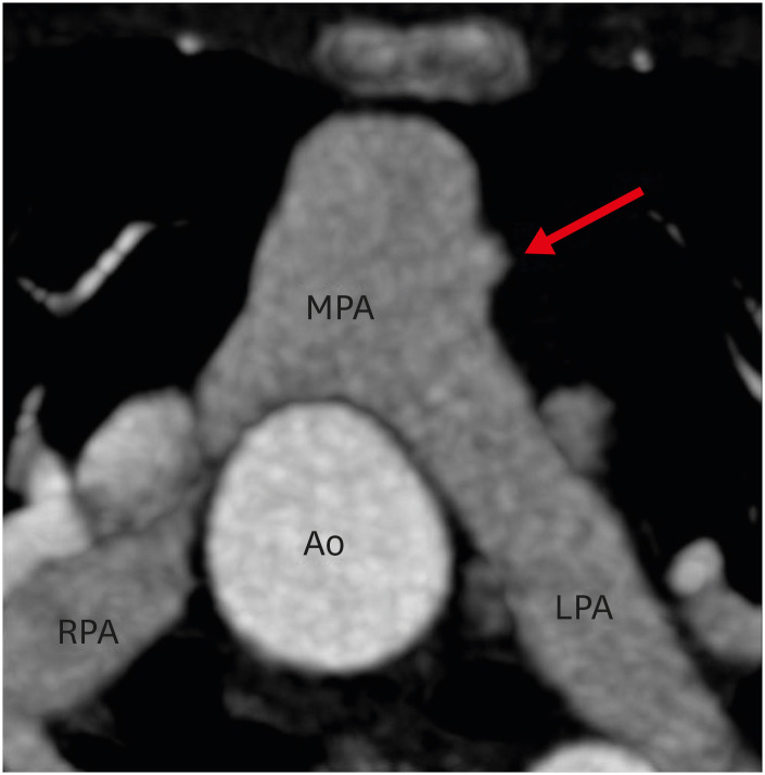
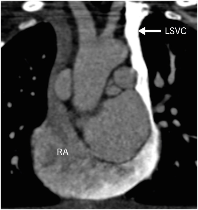
Ventricular septal defect (VSD) is commonly associated with TGA and is seen in approximately 40% of cases.31),32) It is divided into five different categories, as in normally related vessels. These defects are closed during surgery. The small muscular VSD may not be detectable by echocardiography, especially if there is no pressure gradient. CT can detect the location and size of residual VSDs (Figure 18). Similarly, a small saccular aneurysm may be developed at the anastomotic site between the great vessels and the neo-roots (Figure 19). A few other congenital abnormalities like a left-sided superior vena cava (Figure 20), residual VSD, aberrant origin of right subclavian artery (Figure 21) and coarctation of the aorta are also seen with TGA. CT allows the imaging of extracardiac structures and therefore can accurately demonstrate these findings.
Figure 18. Oblique maximum intensity projection CT angiography image in a TGA patient after ASO showing small muscular ventricular septal defect (arrow).
ASO: arterial switch operation, CT: computed tomography, TGA: transposition of the great arteries.
Figure 19. Axial maximum intensity projection CT angiography image in a patient after ASO shows a focal aneurysm of the main pulmonary artery (red arrow).
Ao: neo-aortic root, ASO: arterial switch operation, CT: computed tomography, LPA: left pulmonary artery, MPA: main pulmonary artery, RPA: right pulmonary artery.
Figure 20. Coronal contrast-enhanced CT angiography image in a TGA patient after ASO showing a left-sided superior vena cava draining into the right atrium through the coronary sinus.
ASO: arterial switch operation, CT: computed tomography, LSVC: left superior vena cava, RA: right atrium, TGA: transposition of the great arteries.
Figure 21. Axial maximum intensity projection CT angiography image in a TGA patient after ASO showing aberrant origin of the right subclavian artery (arrow) with a retro-esophageal course.
ASO: arterial switch operation, CT: computed tomography, TGA: transposition of the great arteries.
CONCLUSION
The complications after ASO are common and complicated. A large subset of patients are referred for imaging. Complications like coronary artery occlusion or narrowing may be completely asymptomatic. CT technology is continuously evolving, with the development of innovations such as high pitch mode scanning, ECG-synchronized cardiac imaging, increasing detector width enabling large volume coverage, 3D printing and improved spatial and temporal resolution. These improvements have beaten the challenges involved in cardiac imaging in children. CT provides exquisite details about the postoperative anatomy and complications of ASO, giving information related to both intra-cardiac and extra-cardiac anatomies, coronary arteries and vascular structures. It is, therefore an excellent diagnostic modality for postoperative follow-up of ASO.
Footnotes
Conflict of Interest: The authors have no financial conflicts of interest.
- Conceptualization: Kumar P.
- Writing - original draft: Kumar P.
- Writing - review & editing: Bhatia M.
References
- 1.Ruys TP, van der Bosch AE, Cuypers JA, et al. Long-term outcome and quality of life after arterial switch operation: a prospective study with a historical comparison. Congenit Heart Dis. 2013;8:203–210. doi: 10.1111/chd.12033. [DOI] [PubMed] [Google Scholar]
- 2.Prakash A, Powell AJ, Geva T. Multimodality noninvasive imaging for assessment of congenital heart disease. Circ Cardiovasc Imaging. 2010;3:112–125. doi: 10.1161/CIRCIMAGING.109.875021. [DOI] [PubMed] [Google Scholar]
- 3.Mustard WT, Chute AL, Keith JD, Sirek A, Rowe RD, Vlad P. A surgical approach to transposition of the great vessels with extracorporeal circuit. Surgery. 1954;36:31–51. [PubMed] [Google Scholar]
- 4.Senning A. Surgical correction of transposition of the great vessels. Surgery. 1959;45:966–980. [PubMed] [Google Scholar]
- 5.Jatene AD, Fontes VF, Paulista PP, et al. Anatomic correction of transposition of the great vessels. J Thorac Cardiovasc Surg. 1976;72:364–370. [PubMed] [Google Scholar]
- 6.Lecompte Y, Zannini L, Hazan E, et al. Anatomic correction of transposition of the great arteries. J Thorac Cardiovasc Surg. 1981;82:629–631. [PubMed] [Google Scholar]
- 7.Khairy P, Clair M, Fernandes SM, et al. Cardiovascular outcomes after the arterial switch operation for D-transposition of the great arteries. Circulation. 2013;127:331–339. doi: 10.1161/CIRCULATIONAHA.112.135046. [DOI] [PubMed] [Google Scholar]
- 8.Cohen MS, Eidem BW, Cetta F, et al. Multimodality imaging guidelines of patients with transposition of the great arteries: a report from the American Society of Echocardiography Developed in Collaboration with the Society for Cardiovascular Magnetic Resonance and the Society of Cardiovascular Computed Tomography. J Am Soc Echocardiogr. 2016;29:571–621. doi: 10.1016/j.echo.2016.04.002. [DOI] [PubMed] [Google Scholar]
- 9.DeFaria Yeh D, Foster E. Is MRI the preferred method for evaluating right ventricular size and function in patients with congenital heart disease?: MRI is not the preferred method for evaluating right ventricular size and function in patients with congenital heart disease. Circ Cardiovasc Imaging. 2014;7:198–205. doi: 10.1161/CIRCIMAGING.113.000395. [DOI] [PubMed] [Google Scholar]
- 10.European Society of Cardiology (ESC); European Heart Rhythm Association (EHRA) Brignole M, et al. 2013 ESC guidelines on cardiac pacing and cardiac resynchronization therapy: the task force on cardiac pacing and resynchronization therapy of the European Society of Cardiology (ESC). Developed in collaboration with the European Heart Rhythm Association (EHRA) Europace. 2013;15:1070–1118. doi: 10.1093/europace/eut206. [DOI] [PubMed] [Google Scholar]
- 11.Marcora S, Di Renzi P, Giannico S, Pierleoni M, Bellelli A, Sanders SP. A CT study of coronary arteries in adult mustard patients. JACC Cardiovasc Imaging. 2011;4:89–93. doi: 10.1016/j.jcmg.2010.07.015. [DOI] [PubMed] [Google Scholar]
- 12.Sun Z, Lau I, Wong YH, Yeong CH. Personalized three-dimensional printed models in congenital heart disease. J Clin Med. 2019;8:522. doi: 10.3390/jcm8040522. [DOI] [PMC free article] [PubMed] [Google Scholar]
- 13.Booij R, Dijkshoorn ML, van Straten M, et al. Cardiovascular imaging in pediatric patients using dual source CT. J Cardiovasc Comput Tomogr. 2016;10:13–21. doi: 10.1016/j.jcct.2015.10.003. [DOI] [PubMed] [Google Scholar]
- 14.Han BK, Rigsby CK, Leipsic J, et al. Computed tomography imaging in patients with congenital heart disease, Part 2: Technical recommendations. An expert consensus document of the Society of Cardiovascular Computed Tomography (SCCT): Endorsed by the Society of Pediatric Radiology (SPR) and the North American Society of Cardiac Imaging (NASCI) J Cardiovasc Comput Tomogr. 2015;9:493–513. doi: 10.1016/j.jcct.2015.07.007. [DOI] [PubMed] [Google Scholar]
- 15.Sun Z. Coronary CT angiography with prospective ECG-triggering: an effective alternative to invasive coronary angiography. Cardiovasc Diagn Ther. 2012;2:28–37. doi: 10.3978/j.issn.2223-3652.2012.02.04. [DOI] [PMC free article] [PubMed] [Google Scholar]
- 16.Labounty TM, Leipsic J, Min JK, et al. Effect of padding duration on radiation dose and image interpretation in prospectively ECG-triggered coronary CT angiography. AJR Am J Roentgenol. 2010;194:933–937. doi: 10.2214/AJR.09.3371. [DOI] [PubMed] [Google Scholar]
- 17.Elster A. Impact of new technologies on dose reduction in CT. In: Osborn AG, Abbara S, Elster AD, et al., editors. Yearbook of Diagnostic Radiology. St. Louis, MO: Mosby; 2011. pp. 191–192. [Google Scholar]
- 18.Szymczyk K, Moll M, Sobczak-Budlewska K, et al. Usefulness of routine coronary CT angiography in patients with transposition of the great arteries after an arterial switch operation. Pediatr Cardiol. 2018;39:335–346. doi: 10.1007/s00246-017-1761-z. [DOI] [PMC free article] [PubMed] [Google Scholar]
- 19.Sievers HH, Scharfschwerdt M, Putman LM. In vitro evaluation of physiological spiral anastomoses for the arterial switch operation in simple transposition of the great arteries: a first step towards a surgical alternative? Interact Cardiovasc Thorac Surg. 2015;21:157–162. doi: 10.1093/icvts/ivv114. [DOI] [PubMed] [Google Scholar]
- 20.Ou P, Khraiche D, Celermajer DS, et al. Mechanisms of coronary complications after the arterial switch for transposition of the great arteries. J Thorac Cardiovasc Surg. 2013;145:1263–1269. doi: 10.1016/j.jtcvs.2012.06.009. [DOI] [PubMed] [Google Scholar]
- 21.Morgan CT, Mertens L, Grotenhuis H, Yoo SJ, Seed M, Grosse-Wortmann L. Understanding the mechanism for branch pulmonary artery stenosis after the arterial switch operation for transposition of the great arteries. Eur Heart J Cardiovasc Imaging. 2017;18:180–185. doi: 10.1093/ehjci/jew046. [DOI] [PubMed] [Google Scholar]
- 22.Michalak KW, Sobczak-Budlewska K, Moll JJ, et al. Can we predict potentially dangerous coronary patterns in patients with transposition of the great arteries after an arterial switch operation? Cardiol Young. 2019;29:1350–1355. doi: 10.1017/S104795111900204X. [DOI] [PubMed] [Google Scholar]
- 23.McMahon CJ, Ravekes WJ, Smith EO, et al. Risk factors for neo-aortic root enlargement and aortic regurgitation following arterial switch operation. Pediatr Cardiol. 2004;25:329–335. doi: 10.1007/s00246-003-0483-6. [DOI] [PubMed] [Google Scholar]
- 24.Vasan RS, Larson MG, Levy D. Determinants of echocardiographic aortic root size. The Framingham Heart Study. Circulation. 1995;91:734–740. doi: 10.1161/01.cir.91.3.734. [DOI] [PubMed] [Google Scholar]
- 25.Schwartz ML, Gauvreau K, del Nido P, Mayer JE, Colan SD. Long-term predictors of aortic root dilation and aortic regurgitation after arterial switch operation. Circulation. 2004;110:II128–32. doi: 10.1161/01.CIR.0000138392.68841.d3. [DOI] [PubMed] [Google Scholar]
- 26.Ullmann MV, Gorenflo M, Bolenz C, et al. Late results after extended pulmonary artery reconstruction in the arterial switch operation. Ann Thorac Surg. 2006;81:2259–2266. doi: 10.1016/j.athoracsur.2006.01.037. [DOI] [PubMed] [Google Scholar]
- 27.Lembcke A, Dohmen PM, Dewey M, et al. Multislice computed tomography for preoperative evaluation of right ventricular volumes and function: comparison with magnetic resonance imaging. Ann Thorac Surg. 2005;79:1344–1351. doi: 10.1016/j.athoracsur.2004.09.030. [DOI] [PubMed] [Google Scholar]
- 28.Tanıdır IC, Ozturk E, Sahin M, Haydin S, Guzeltas A. Cannot extubate a newborn patient after an arterial switch operation? Check major aortopulmonary collaterals! Rev Bras Cir Cardiovasc. 2020;35:593–596. doi: 10.21470/1678-9741-2019-0109. [DOI] [PMC free article] [PubMed] [Google Scholar]
- 29.Sugimoto A, Ota N, Sakamoto K. Pulmonary haemorrhage due to an aortopulmonary collateral artery after arterial switch. Cardiol Young. 2016;26:579–581. doi: 10.1017/S1047951115001328. [DOI] [PubMed] [Google Scholar]
- 30.Toker A, Tireli E, Bostanci K, Ozcan V, Dayioğlu E. Uncommon complication of arterial switch operation: tracheobronchial compression. Ann Thorac Surg. 2000;69:927–929. doi: 10.1016/s0003-4975(99)01400-9. [DOI] [PubMed] [Google Scholar]
- 31.Van Praagh R, Weinberg PM, Calder L, Buckley LF, Van Praagh S. The transposition complexes: how many are there? In: Davila JC, editor. Second Henry Ford Hospital International Symposium on Cardiac Surgery. New York, NY: Appleton-Century-Crofts; 1977. pp. 207–213. [Google Scholar]
- 32.Van Praagh R. Anatomic variations in transposition of the great arteries. In: Takahashi M, Wells WJ, Lindesmith GG, editors. Challenges in the Treatment of Congenital Cardiac Anomalies. Mount Kisco, NY: Futura; 1986. pp. 107–135. [Google Scholar]


