Abstract
Motile cilia power cell locomotion and drive extracellular fluid flow by propagating bending waves from their base to tip. The coordinated bending of cilia requires mechanoregulation by the radial spoke (RS) protein complexes and the microtubule central pair (CP). Despite their importance for ciliary motility across eukaryotes, the molecular function of the RSs is unknown. Here, we reconstituted the Chlamydomonas reinhardtii RS head that abuts the CP and determined its structure using single-particle cryo-EM to 3.1 Å resolution, revealing a flat, negatively-charged surface supported by a rigid core of tightly intertwined proteins. Mutations in this core, corresponding to those involved in human ciliopathies, compromised stability of the recombinant complex, providing a molecular basis for disease. Partially reversing the negative charge on the RS surface impaired motility in C. reinhardtii. We propose that the RS head architecture is well-suited for mechanoregulation of ciliary beating through physical collisions with the CP.
The motile cilium, also referred to as the eukaryotic flagellum, is an organelle that protrudes from the cell body and is present in one or multiple copies on the cell surface. Cilia beating is generated by waves of bending that propagate from the base of the structure towards the distal tip. By pushing against the surrounding fluid, cilia beating can facilitate cell locomotion, as occurs in many single cell eukaryotes and mammalian sperm. In the case of stationary cells within a tissue, motile cilia can drive extracellular fluid flow1, which can transport particles in respiratory tracts of mammals2.
The axoneme, the core structure of the motile cilium, is composed of nine outer microtubule doublets that, in most cases, surround two inner single microtubules termed the central pair (CP) (Fig. 1a). The doublets and CP are decorated with numerous proteins that display periodic spacing along the length of the axoneme, including the nexin-dynein regulatory complex (N-DRC) and dynein motors, both of which bridge adjacent doublets1 (Fig. 1a). The dyneins are classified as inner dynein arms (IDAs) or outer dynein arms (ODAs), based on their attachment point to the microtubule, and induce sliding between outer doublets3. To convert linear sliding into a propagating bend, dyneins on opposite sides of the axoneme alternate their activity, switching between active and inactive states4. In fast-beating cilia this switching mechanism occurs in tens of milliseconds or less, which suggests a mechanism for regulating dynein activity through mechanical feedback5. In addition, beating can be modulated by calcium and posttranslational modifications6,7.
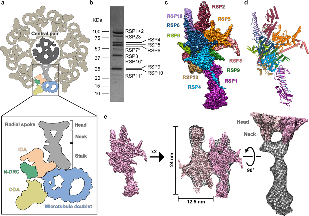
Fig.1. Reconstitution and cryo-EM structure of the radial spoke head and neck.
a, Schematic of an axoneme cross section from Chlamydomonas. Nine repeating units surround the central pair (CP); one is colored according to the different complexes composing it (in box): ODA (outer dynein arm, yellow), IDA (inner dynein arm, peach), N-DRC (nexin-dynein regulatory complex, green) and RS (radial spoke, grey) are attached to the microtubule doublet (blue). Different regions of the RS are indicated. b, Coomassie-stained SDS-PAGE of the RS head-neck complex. Proteins that were not visible in the cryo-EM map are marked with an asterisk. Uncropped gel image shown in Supplementary Figure 1. c, Cryo-EM map of the RS head-neck complex colored according to its constituent chains. d, Model for the RS head-neck built into the map in c. e, Two copies of the recombinant RS head-neck cryo-EM map in c (pink) docked into a subtomogram-averaging map (black mesh) of native Chlamydomonas RS (EMD-1941)8.
Among key regulators of axonemal dynein activity are the radial spokes (RSs), large protein complexes conserved in motile cilia that exhibit a planar waveform. The RSs have been most studied in the biflagellate algae Chlamydomonas reinhardtii. Mutations in the radial spoke proteins (RSPs), many of which abolish large parts of the structure8,9, result in paralysis in Chlamydomonas10,11. In humans, mutations in RSPs cause primary ciliary dyskinesia (PCD), a disease associated with various breathing disorders and infertility12–16.
Structurally, the RSs are T-shaped protein complexes that are attached at their base to the outer doublets and project with a flat “head” toward the center of the axoneme (Fig. 1a)8,9,17. Along a 96-nm repeating unit of the Chlamydomonas axoneme, there are two RSs that differ in their attachment to the outer doublet, but are likely identical in the head region8,9,18. The Chlamydomonas RSs are composed of 23 proteins, about half of which are not homologous to proteins of known structure or function19,20. Structures of the RSs are currently limited to 3–4 nm resolution8,9,21, and thus cannot inform the organization and function of their constituent RSPs.
The RS head and the CP are spaced apart in the straight axoneme21, but the two structures come in contact when the axoneme bends22. Experiments that alter the length of the RS reveal the separation distance between the RS and CP is critical for regulating cilia beating21. Due to their physical location and rigidity, evident from well-defined averaged subtomograms8,9, RSs were proposed to transmit forces generated by dyneins at the axoneme periphery to the CP, and/or to convey signals from the CP to dyneins17. However, how the RS structure relays mechanical signals in the axoneme and controls dynein activity, in concert with other complexes, is still poorly understood.
In this study, we sought to obtain the structure of the Chlamydomonas RS head, since this region directly contacts the CP and contains the majority of identified PCD mutations. We reconstituted the Chlamydomonas RS head and adjacent neck from recombinant proteins and solved the structure using single-particle cryo-electron microscopy (EM). The structure reveals a rigid structure with an acidic surface that we propose is well-suited to withstand collisions and minimize prolonged interactions with the CP. Utilizing our recombinant system, we show that disease-causing mutations undermine RS integrity and stability, thus providing insights into the structural basis for RS-based PCD.
RESULTS
Reconstitution of the RS head and neck
The RS is composed of a long ~28 nm stalk attached at its base to the outer doublets, a bifurcated neck, and a flat head projecting towards the CP8,9 (Fig. 1a). We sought to express a stable recombinant protein complex of the head region. To identify all proteins that form the RS head, we tagged two established head-localized RSPs (the C-terminal region of RSP321,23 and RSP48,20) and co-expressed them in a baculovirus expression system along with all other known RSPs (total of 16), except those that are positioned near the microtubule docking site (see Online Methods). Tandem affinity purification of His-tagged RSP4 and GST-tagged RSP3 (aa 160–516) yielded a complex composed of 12 of the 16 proteins (Fig. 1b, Supplementary Table 1) that corresponds to the RS head and neck (see below). Using single-particle cryo-EM, we obtained a three-dimensional reconstruction of the head-neck complex at an average resolution of 3.1 Å (Fig. 1c, Extended Data Figs. 1 and 2 and Table 1). The high-resolution map of the head-neck complex allowed us to build atomic models for nine proteins (Fig. 1d, Supplementary Table 2, Supplementary Video 1 and Online Methods), most of which were built de novo, since reliable structure predictions were lacking. Interactions between RSPs in our model agree with previously identified head RSP interactions determined in crosslinking and pulldown assays24 (Supplementary Table 3).
Table 1.
Cryo-EM data collection, refinement and validation statistics
| RS head–neck complex (“map 1”)*(EMD-22446, PDB 7JRJ) | RS head minimal complex (“map 7”)**(EMD-22444, PDB 7JR9) | |
|---|---|---|
| Data collection and processing | ||
| Magnification | 105,000 | 130,000 |
| Voltage (kV) | 300 | 300 |
| Electron exposure (e–/Å2) | 70.0 | 73.3 |
| Defocus range (μm) | -0.8 to −1.5 | -1 to −2.5 |
| Pixel size (Å) | 0.835 (0.4175) | 0.855 (0.4275) |
| Symmetry imposed | None | None |
| Initial particle images (no.) | 942,951 | 1,775,590 |
| Final particle images (no.) | 136,659 | 251,088 |
| Map resolution (Å) | 3.1 | 2.95 |
| FSC threshold | 0.143 | 0.143 |
| Map resolution range (Å) | 2.6–5.0 | 2.6–4.5 |
| Refinement | ||
| Initial model used | PDB 7JR9 | de novo |
| Model resolution (Å) | 2.5 | 2.9 |
| FSC threshold | 0.143 | 0.143 |
| Map sharpening B factor (Å2) | -60 | -50 |
| Model composition | ||
| Non-hydrogen atoms | 22,924 | 10,021 |
| Protein residues | 2,932 | 1,300 |
| Unknown protein residues | 127 | 14 |
| B factors (Å2) | ||
| Protein | 66.25 | 57.78 |
| Unknown protein residues | 96.14 | 110.36 |
| R.m.s. deviations | ||
| Bond lengths (Å) | 0.006 | 0.008 |
| Bond angles (°) | 0.591 | 0.809 |
| Validation | ||
| MolProbity score | 1.59 | 1.38 |
| Clashscore | 5.14 | 4.11 |
| Poor rotamers (%) | 0.04 | 0 |
| Ramachandran plot | ||
| Favored (%) | 95.42 | 96.94 |
| Allowed (%) | 4.58 | 3.06 |
| Disallowed (%) | 0 | 0 |
See Extended Data Figs. 1–2.
See Extended Data Fig. 5.
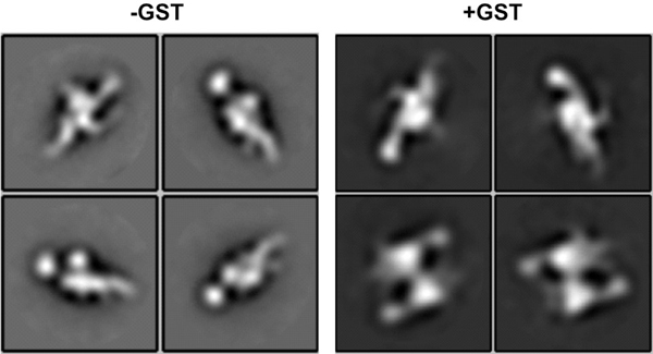
To put our head-neck structure into context of the native RS, we docked our reconstruction into the subtomogram-averaged map for the endogenous RS in the Chlamydomonas axoneme8 (Fig. 1e). From the side-view, our reconstruction filled the head and the neck extending from the head towards the stalk. We could fit in two copies with a two-fold symmetry, which is consistent with prior conclusions that the native RS is a dimer based upon its shape8,9 and labeling studies21. Our fit suggests an interaction interface between the two protomers, but we did not observe a dimer population (Extended Data Fig. 3). However, prior to cleaving the GST tag on RSP3 in our purification, we observed a subpopulation of two-fold symmetric head dimers by negative-stain EM (Extended Data Fig. 3). GST, which is a dimer itself, could create a high local concentration of the two head protomers, enabling them to interact. Additional factors in the stalk are likely required for stable dimerization in the native RS.
In conclusion, our high-resolution cryo-EM structure of the head-neck recombinant complex is consistent with previous biochemical data and fits well into the subtomogram-averaged map of the native complex8, indicating that it reliably represents one half of the native RS head and neck.
Architecture of the RS head
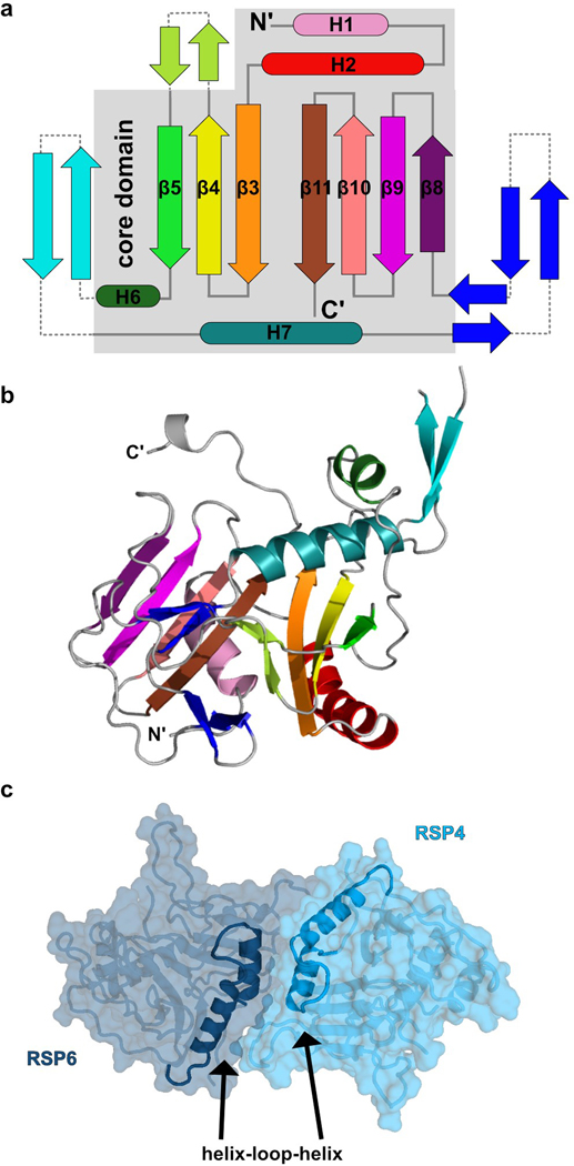
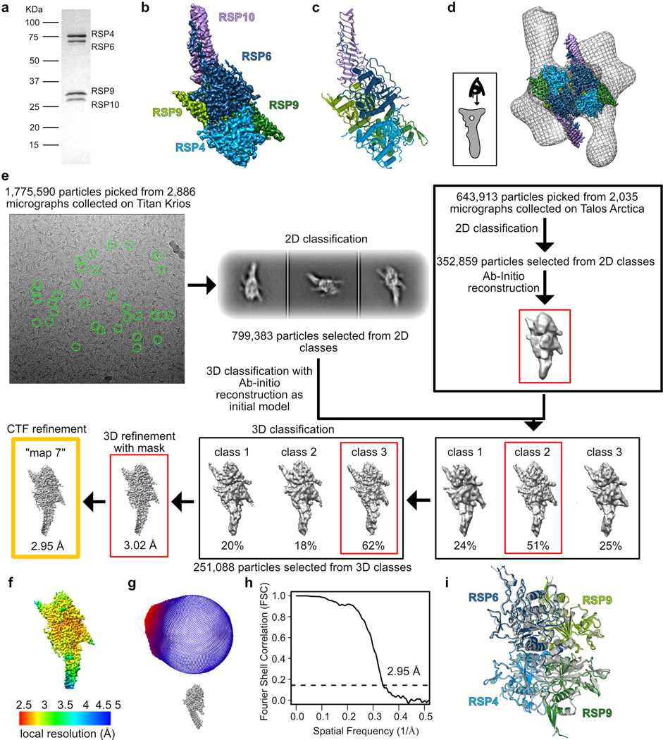
The RS head is composed of 8 different proteins. RSP4, RSP6 and RSP9 comprise a rigid core at the center and act as a scaffold for RSP1, RSP2, RSP3, RSP5 and RSP10, which form protrusions at the periphery (Fig 2a). Intriguingly, RSP9, RSP4 (aa 105–425), and RSP6 (aa 102–412) all share a common fold (Fig. 2b) that is not found in any other protein structure in the wwPDB, as assessed by the Dali server25. The novel fold in RSP4, RSP6 and RSP9 is composed of two anti-parallel beta-sheets connected through α-helices and loops with varying lengths (Extended Data Fig. 4a–b). The three core proteins form a pseudo-tetramer, composed of two identical RSP9 chains and one copy of RSP4 and RSP6 (Fig. 2c, Extended Data Fig. 4c). The tight polar and hydrophobic interactions between the four subunits (Fig. 2d) form a unique architecture that creates a firm core for the RS head. In support of this idea, we prepared a recombinant complex composed of the three core proteins (RSP4, 6 and 9) and RSP10 and determined its structure using single-particle cryo-EM to 2.95 Å, revealing that the tetrameric core is almost identical (r.m.s.d. of 0.6 Å) in the head-neck and this minimal head structure (Extended Data Fig. 5 and Table 1). Thus, the RS head core is a rigid unit of tightly interlocked proteins composed of a unique protein fold.
Fig. 2. Architecture of the radial spoke head.
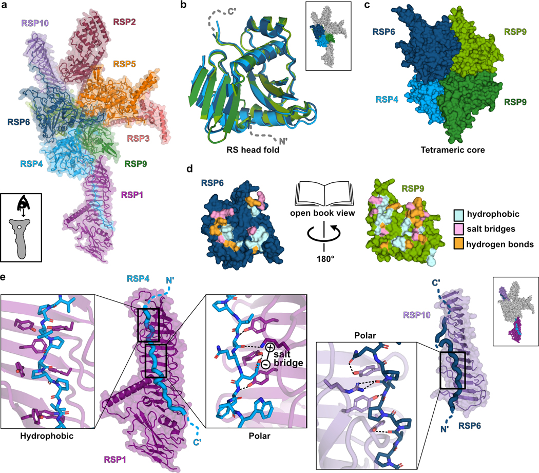
a, RS head surface in cartoon and surface presentations (view indicated in box). b, Superposition of the four core subunits. Some loops were removed for clarity. Box shows RS head surface highlighting the core proteins for context. c, Arrangement of the core proteins in a tetramer. Only the middle domains of RSP4 and RSP6 are shown for clarity. d, Open book presentation for one of the interfaces within the tetrameric core. Residues from RSP6 and RSP9 that interact with each other are colored according to the type of interaction. e, The C-terminal tails of RSP4 and RSP6 are housed in the grooves of the curved beta sheet (MORN repeats) in RSP1 and RSP10, respectively. Box on the top right shows RS head surface highlighting these protrusions for context. Three boxes zoom into specific regions, showing multiple aromatic residues pointing from the MORN-repeats beta strands towards the proline-rich chains. Hydrophobic interactions between aromatic and proline residues, hydrogen bonds (dashed lines) and a salt bridge are shown.
From the tetrameric core, the C-termini of RSP4 and RSP6 emerge in opposing directions as extended chains that are enveloped by RSP1 and RSP10, respectively (Fig. 2e). As predicted from their sequences, the latter two proteins are composed of multiple beta-strands with the configuration of membrane occupation and recognition nexus (MORN) repeats, forming elongated curved beta-sheets abundant in aromatic residues26. The concave surfaces of RSP1 and RSP10 accommodate the proline-rich C-termini of RSP4 and RSP6, respectively, through a network of hydrogen bonds, hydrophobic and electrostatic interactions (Fig. 2e). The long MORN-repeat domains significantly extend the surface of the RS head and lock its core in place.
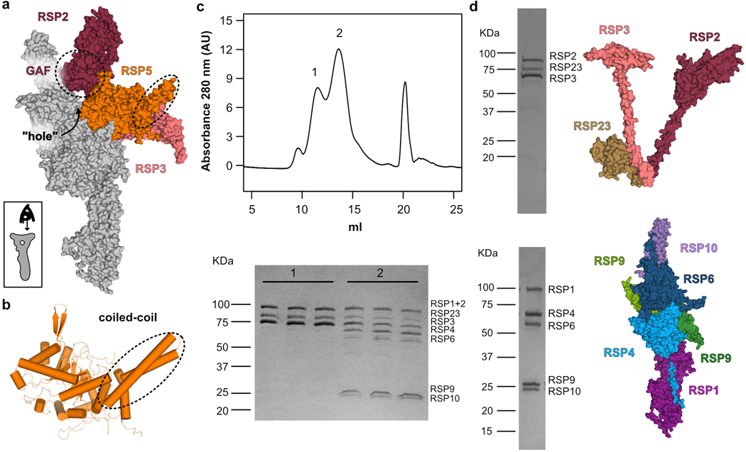
While the RSP1 and RSP10 protrusions are continuous with the core, RSP2, RSP3 and RSP5 form a protruding segment that is attached to the core at only two positions, creating a “hole” in the head (Extended Data Fig. 6a). The RSP2 and RSP3 protrusions are likely less rigid, as the density of the cryo-EM map was poor in these regions, with an average resolution of 5 Å or lower (Extended Data Fig. 2a). Yet, we could clearly resolve their high helical content and that the RSP2 protrusion contains a GAF domain that serves as an anchor to the core. The second link is through RSP5, which bridges the RSP2 and RSP3 protrusions (Extended Data Fig. 6a). As predicted from its sequence, RSP5 has an aldo-keto reductase (AKR) fold linked to a coiled coil positioned at the head surface (Extended Data Fig. 6b). No cofactor density was observed in the cryo-EM map, and the catalytic residues required for AKR activity27 are absent, suggesting that RSP5 has lost its enzymatic function and instead has a structural role in stabilizing the RS head. Consistent with this idea, co-expressing all proteins that compose the head-neck in the absence of RSP5 resulted in the purification of two complexes (Extended Data Fig. 6c), which were stable as individual units when expressed and purified separately (Extended Data Fig. 6d). Previous studies concluded that the RS head is composed of only five proteins: the three core proteins (RSP4, RSP6 and RSP9) and the two MORN-repeat proteins (RSP1 and RSP10)8,28. Our structure shows that this five-protein unit is indeed the center of the head, but the segment created by the other three proteins (RSP2, RSP3 and RSP5) is also integral to its support.
Point mutations in the RS head compromise its stability
Using our model for the RS head, and owing to the sequence similarities between C. reinhardtii and humans (Extended Data Fig. 7a), we mapped five known point mutations in the human orthologs that compromise cilia motility and hence cause PCD12–14 onto the algae structure with high confidence (Fig. 3a, Extended Data Fig. 7b–f and Table 2). Most mutations are localized to the interior of RSPs, and thus could destabilize the folded core of the proteins. Arg261 is near a junction of three RSPs, and thus the in-frame deletion of this residue might affect their interactions. To test these predictions, we generated the corresponding mutant RS head complexes and characterized the effect of mutation on complex composition and stability.
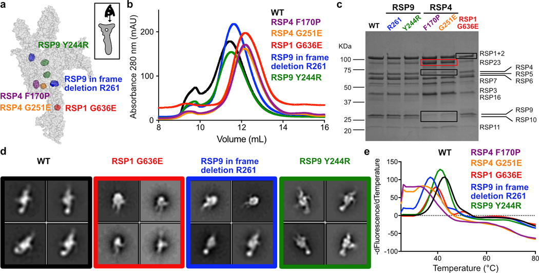
Fig. 3. Characterization of ciliopathy-based radial spoke head mutants.
a, Positions of mutations made in the recombinant Chlamydomonas head-neck complex are shown in spheres. The RS head surface is shown from the CP view, as indicated at the top right, and is transparent (not all mutations are on the head surface). RSP9 appears in two copies and thus, positions mutated in RSP9 are indicated twice. See Extended Data Fig. 6b–f for more details. b, SEC profiles of purified recombinant RS head variants, showing all mutants elute later than wild-type, except for Y244R in RSP9. c, Coomassie-stained SDS-PAGE of purified recombinant head variants. Black boxes indicate reduced amounts of protein compared to wild-type. Red box indicates elevated amounts of protein in RSP4 mutants, which is likely a chaperone. Uncropped gel image is shown in Supplementary Figure 1. d, Representative negative-stain EM class averages for recombinant RS head variants. Box size is 4.4 nm. e, Representative melting curves for recombinant RS head variants, showing all mutants denature at a lower temperature than WT. Apparent denaturation temperatures are reported in Table 2.
Table 2.
Point mutations in radial spoke head proteins that cause PCD
| H. Sapiens RSP | Mutation | C. reinhardtii ortholog | Corresponding mutation in C. reinhardtii | Apparent denaturation temperature* | References |
|---|---|---|---|---|---|
| Wild-type | 43±0.5 | ||||
| RSPH4A | Ala369Pro | RSP4 | Phe170Pro | 32±1 | 12 |
| RSPH4A | Gly464Glu | RSP4 | Gly251Glu | 35±1 | 12 |
| RSPH9 | In frame deletion of Lys268 | RSP9 | In frame deletion of Arg261 | 37±0.5 | 12, 13, 14 |
| RSPH9 | His251Arg | RSP9 | Tyr244Arg | 41±0.5 | 12 |
| RSPH1 | Gly103Asp | RSP1 | Gly636Asp | 39±0.5 | 14 |
Average of three repeats. Error is standard deviation of the mean. See Fig. 3e for representative melting curves.
Three mutants, with a mutation in RSP4 or RSP1, formed significantly smaller complexes compared to the wild-type complex, as evident from size-exclusion chromatography (SEC), SDS-PAGE and negative-stain EM (Fig. 3b–d and Extended Data Fig. 7g). These mutants demonstrate that specific point mutations lead to disassembly of the RS head, consistent with absence of several RSPs from cilia in PCD patients with the corresponding mutations12. In contrast, the composition and assembly of two RSP9-mutant complexes appeared largely unaffected (Fig. 3b–d).
To further test the effect of point mutations on complex stability, we performed thermal denaturation experiments on all recombinant variants of the Chlamydomonas RS head (Fig. 3e and Table 2). All mutants denatured at lower apparent melting temperatures than wild-type, indicating their decreased stability. The RSP4 mutants, that had the most severe assembly phenotypes, denatured at the lowest temperatures. Surprisingly, an RSP9 mutant (in-frame deletion of Arg261) that seemed to have a milder assembly phenotype than the RSP1 mutant, denatured at a lower temperature. The RSP9 mutant Y244R, which did not have an apparent effect on RS head assembly, also displayed a melting temperature lower than the wild-type complex, suggesting that its stability was also perturbed and potentially could result in impaired cilia motility and disease. Together, these five recombinant PCD-based mutants show how single point mutations undermine RS head assembly and stability, and emphasize the requirement of a rigid RS head to enable physiologically efficient cilia motility.
Intertwined proteins connect the RS head and neck
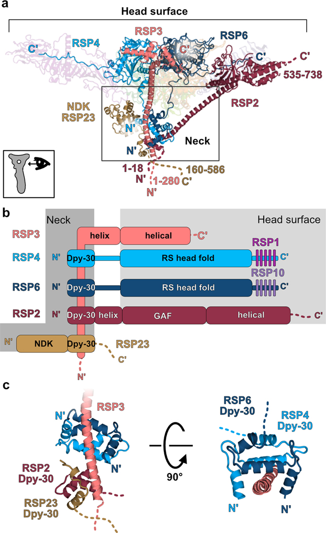
Our structure of the RS head-neck complex reveals that the neck is composed of the nucleotide diphosphate kinase (NDK) domain of RSP23 and segments of four head proteins (RSP2, RSP3, RSP4 and RSP6) (Fig. 4a–b). For RSP4 and RSP6, the polypeptide chain between the head and the neck does not adopt a defined secondary structure. In contrast, RSP2 and RSP3 extend remarkably long (60–70 amino acids) helices from the head into the neck (Fig. 4a). Within the neck are several triple-helix Dpy-30 domains that wrap around the RSP3 helix. The N-terminal Dpy-30 domains of RSP4 and RSP6 dimerize and dock onto a hydrophobic face of an amphipathic-helical region of RSP3 (Fig. 4c). Based on their sequences, RSP2 and RSP23 contain Dpy-30 domains as well29, which are partially modeled in our structure also wrapping together around the helical RSP3 (Fig. 4c). Interestingly, RSP7 and RSP11, not resolved in our reconstruction, are predicted to bind RSP3 further down the RS stalk via an RIIa domain, which closely resembles the Dpy-30 fold23. Therefore, at least three pairs of Dpy-30 domains from different RSPs, and possibly others not visible in our structure, dock onto RSP3. The specificity of each region within RSP3 for a certain Dpy-30 pair may arise from physical proximity created by anchoring other domains of the docked RSPs, rather than from sequence. Supporting this hypothesis, the region of RSP3 that binds RSP4 and RSP6 in our structure was reported to co-purify in vitro with the human Dpy-30 protein23.
Fig. 4. Intertwined proteins connect the radial spoke head and neck.
a, Side-view (as shown at the bottom left) of the RS head-neck, depicting the N- and C-termini of RSP2, RSP3, RSP4 and RSP6, showing these proteins extend from the head surface to the neck (indicated with a box). RSP3 is expected to extend even further into the stalk with another 280 amino acids not modeled in our structure. Numbers indicate the range of amino acids not modeled. NDK – nucleotide diphosphate kinase domain of RSP23 positioned at the neck. Other chains in the complex are transparent for clarity. b, Domain organization of RSPs that participate in forming the neck. Dpy-30 domains of all proteins are anchored on RSP3 at the neck. C-terminal tails of RSP4 and RSP6 are bound by MORN repeat proteins (RSP1 and RSP10). Domains found at the head surface have a light grey box background. Domains found at the neck have a dark grey background. Dashed lines indicate unmodeled regions. c, Dpy-30 domains of RSP4 and RSP6 dimerize and bind the RSP3 helix. Parts of the RSP2 and RSP23 Dpy-30 domains, also interacting with RSP3, are shown.
Overall, the binding of the Dpy-30 domains in RSP2, RSP4 and RSP6 to RSP3 seems to stabilize and position the head relative to the neck. Similarly, placing the RSP23 Dpy-30 domain on RSP3 could orient the neck relative to the stalk, where the remaining RSP23 polypeptide chain presumably extends to. Thus, the RSPs that compose the RS neck are intertwined and anchored at various regions of the RS, forming a stable buttress-like structure and supporting the RS head.
The RS head surface is flat and negatively charged
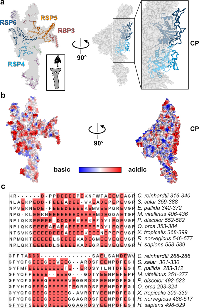
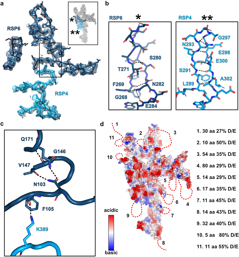
A notable feature of the RS head is its large and uniformly flat surface that faces the CP (Fig. 5a). RSP3 and RSP5, at the head periphery, contribute alpha-helices to the flat surface. However, the center of the surface is primarily composed of long loops and beta-hairpins (Fig. 5a). Many of these loops, especially in RSP4 and RSP6, are well-organized; the main chain and large side-chains could be clearly resolved in the cryo-EM map (Extended data Fig. 8a). For some loops, the structure is stabilized by hydrogen bonds within the loop main chain and side chains (Extended data Fig. 8b). The loops at the surface are supported by the tightly-packed folds that compose the RS head scaffold (Fig. 2), and some are held in place by lateral interactions with neighboring loops (Extended data Fig. 8c).
Fig. 5. The radial spoke head surface is composed of conserved acidic loops.
a, Left - view of the RS head surface from the CP (as shown at the bottom right), showing in cartoon presentation only residues that are closest to the surface. RSPs that contribute a significant surface area to the center of the flat surface are indicated. Right – the surface is rotated 90°, such that the CP is on the right. Several loops from RSP4 and RSP6 point towards the CP. b, Electrostatic volume of the RS head, generated in PyMol, is shown in the same views presented in a. In the view of the head surface (left), the closest regions to the surface are opaque. Many residues at the surface, pointing to the CP, are acidic (red). c, Multiple sequence alignment of two loops in RSP6, showing the acidic patches rich with Glu and Asp residues (red background) are conserved. Alignment was performed with T-Coffee30 and the figure was made in Jalview31.
Many of the loops at the head surface are abundant in acidic residues. An electrostatic map of the RS head shows that the flat surface facing the CP has a pronounced negative potential, particularly in the central region (Fig. 5b). Furthermore, the RS head surface is likely to be even more acidic than visualized by the electrostatic map, since several disordered surface loops that could not be modeled in the structure are also acidic (Extended data Fig. 8d). Importantly, the presence of acidic residues in these loops is conserved from ciliated single cell organisms to humans (Fig. 5c), suggesting a conserved function.
Perturbing the acidic surface of RS head affects Chlamydomonas motility
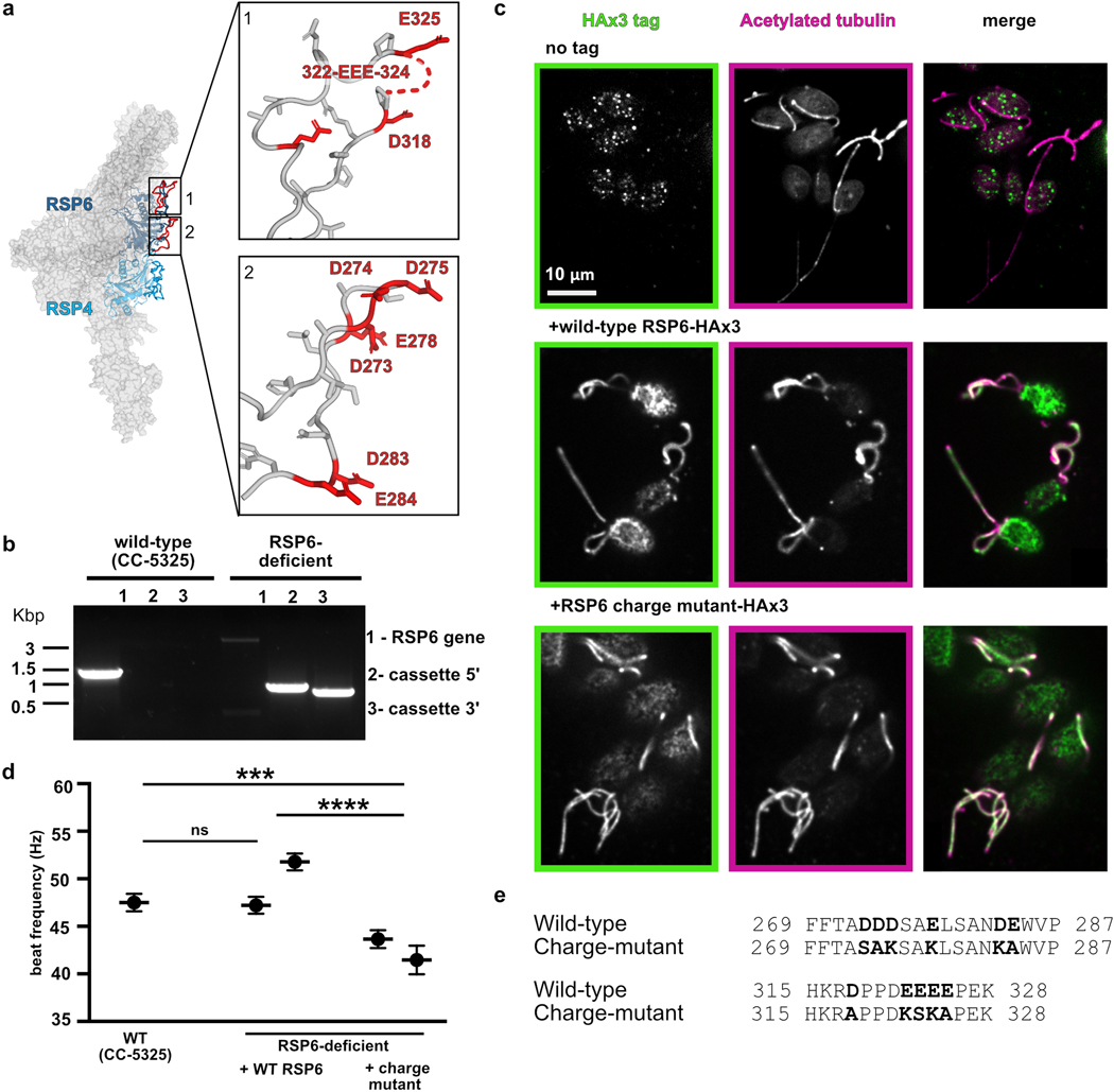
To test whether the loops at the head surface are important for function, we mutated several loop acidic residues and examined the effect on motility of C. reinhardtii. We chose acidic residues in two well-resolved loops in RSP6, since they are conserved and positioned at the center of the RS head (Extended Data Fig. 9a). To introduce the mutations into Chlamydomonas, we used a strain lacking RSP632 that could be complemented (Extended Data Fig. 9b and Online Methods). The RSP6-deficient Chlamydomonas strain exhibited a jerky swimming motion (Supplementary Video 2), as was observed for other strains lacking RSP633. Complementing this RSP6-deficient strain with the wild-type RSP6 gene, tagged with a C-terminal HAx3 tag, resulted in the expression and incorporation of RSP6 into the flagella, as verified by immunofluorescence (Extended Data Fig. 9c), and fully restored motility in terms of swimming pattern and beat frequency (Fig. 6a–b, Extended Data Fig. 9d and Supplementary Video 2). Specifically, the average beat frequencies of the RSP6-rescued strains (47–52 Hz) were comparable to that of the wild-type strain (48±1 Hz), and consistent with the reported beat frequency of 50–60 Hz, for wild-type cells34 (Extended Data Fig. 9d). We next mutated two surface loops in the RSP6 gene, converting 11 glutamic and aspartic acids to serine, lysine or alanine residues (Extended Data Fig. 9e). When expressed in the RSP6-deficient strain, the mutated RSP6 protein, hereafter referred to as the RSP6-charge mutant, was localized to the flagella, suggesting that it and the entire RS complex was properly folded and incorporated in the axoneme (Extended Data Fig. 9c). However, RSP6-deficient Chlamydomonas strains expressing the RSP6-charge mutant exhibited an abnormal and heterogenous swimming pattern. In particular, some cells swam with straight paths, resembling the wild-type strain, while others exhibited jerky motion and moved in a restricted location in a spiral-shaped path (Fig. 6a and Supplementary Video 2). Interestingly, we occasionally observed straight-swimming cells that suddenly switched to a jerky movement, suggesting that the swimming patterns can interconvert. This swimming phenotype of jerky motion, as well as heterogeneity in swimming behavior of cells from the same colony, has been observed previously in Chlamydomonas strains with malfunctioning RSs35.
Fig. 6. Perturbing the acidic radial spoke head surface affects Chlamydomonas motility.
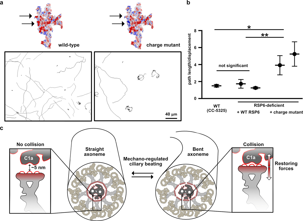
a, Representative paths of RSP6-deficient Chlamydomonas cells complemented with wild-type RSP6 (left) or with the RSP6-charge mutant (right). A predicted electrostatic volume of the RS head is shown for each strain, and arrows indicate the loops that differ between the strains. b, Average ratios of path length/displacement measured for Chlamydomonas wild-type cells (n=65), two clones of RSP6-deficient strain rescued with wild-type RSP6 (n=30 and 60), and two clones of the RSP6 charge mutant (n=63 and 74). Data are shown as mean and s.e.m. Statistical significance was determined by a one-way ANOVA with Holm-Sidak test. *p<0.1; **p<0.01. Source data for graphs are available online. c, Schematic of a straight (left) and bent (right) axoneme cross section. The RS head directs a negatively-charged flat surface, composed primarily of loops, towards the CP, exemplified by the C1a projection (insets), which may have an acidic surface as well (indicated by a red line). In the straight axoneme the CP and RS head are ~ 5 nm apart21. In bent regions there are structural rearrangements to the axoneme4,39,40 (illustrated here as slight distortion to axoneme diameter, but the drawing is not based on experimental data), which may bring RS heads to collide with the C1a projection21,42. We propose that the RS-CP collision generates restoring forces (red arrows) that repel the RS from the CP and restore axoneme geometry to allow bend propagation.
To quantitively compare the rescue with wild-type and the RSP6-charge mutant, we calculated the ratio between the cell’s path length (overall distance travelled) and its net displacement (distance between starting point and end point); a higher ratio indicates an indirect swimming path. Chlamydomonas cells with the RSP6-charge mutant exhibited on average a 2–3-fold higher ratio than clones with wild-type RSP6 (Fig. 6b). In addition, the average beat frequency of strains expressing the RSP6-charge mutant was lower (41–44 Hz) than of strains expressing wild-type RSP6 (Extended Data Fig. 9d). These results suggest that the acidity of the loops at the RS head surface contributes to efficient cilia beating and swimming behavior.
DISCUSSION
In this study, we have reconstituted the RS head-neck complex and solved its structure to 3.1 Å resolution using cryo-EM single-particle reconstruction. Our data reveal a rigid structure that is created through interlocking interactions of multiple proteins with diverse folds. Using our recombinant system, we analyzed how human PCD mutations affect the stability and integrity of the RS head. Through genetic complementation studies, we also demonstrate the role of structured loops at the surface of the RS head in cell motility. Together, our data provide new insights into the assembly and mechanical roles of the Chlamydomonas RS and the structural basis of human ciliopathies involving the RS, detailed below.
Cryo-ET work has revealed that the RS from Chlamydomonas flagella8,9 and from cilia in human airways36 both possess a flat head surface and a bifurcated neck, but the human RS head appears smaller and lacks some of the protrusions present in the Chlamydomonas RS. Our structure and reconstitution experiments reveal modular domains of the Chlamydomonas RS head that may explain such species-specific variations. The center of the Chlamydomonas RS head consists of a tightly-packed tetramer of RSPs (RSP4, RSP6 and a homodimer of RSP9) and two long peripheral extensions composed of MORN-repeat proteins (RSP1 and RSP10) (Fig. 2), forming a stable complex (Extended Data Fig. 6d). Humans have orthologs for all five Chlamydomonas RS head proteins17, but RSP4HA (RSP4) and RSPH1 (RSP1) are expressed primarily in the ciliated epithelia of the airways, whereas RSP6HA (RSP6) and RSP10HB (RSP10) are expressed selectively in the testis14,37. Based on these observations and the structural homology between RSP4 and RSP6, and between RSP1 and RSP10, we propose that the human RS head center has tissue-specific compositions, containing different sets of homodimers, namely RSP4HA, RSPH9 and RSPH1 in ciliated epithelia, and RSP6HA, RSPH9 and RSP10HB in sperm. Supporting this hypothesis, recombinantly expressed RSP4HA, RSPH1 and RSPH9 could form a stable structure composed of a globular core and two long MORN extensions, in the absence of RSP6HA and RSP10HB38. The two tissue-specific human RS heads might confer unique regulatory activities in the beating of axonemes in these different cell types.
RSP2, RSP3, and RSP23 constitute another stable protein module (Extended Data Fig. 6d) that scaffolds the RS neck. The long helices of RSP2 and RSP3 and Dpy-30 domain pairs (Fig. 4) are found in human RSPs as well, and presumably support the human RS head in a similar manner. The protruding segment at the RS head surface composed of RSP2, RSP3 and RSP5 (Extended Data Fig. 6a) is not conserved, and hence the human RS head in the airways appears to be smaller than the Chlamydomonas RS head36.
The duplication of RSP1 and RSP4 chains in the human RS head, as discussed above, is expected to create a more pronounced effect on RS head stability than that reported here for the corresponding mutations in Chlamydomonas orthologs. It has been previously shown that RSP4 and RSP9 are each required to form the Chlamydomonas RS head. Cryo-ET and sub-tomogram averaging of Chlamydomonas RSs in strains lacking either RSP48 or RSP99 revealed headless radial spokes. Although the PCD-based point mutations we made in RSP4 led to a comparable phenotype, the PCD-based point mutations in RSP9 did not result in a severe assembly phenotype (Fig. 3). Consistently with this result, immunofluorescence studies of airway cilia bearing the corresponding PCD mutations showed that the mutant RSPH9 was absent, but other head RSPs were detected12, suggesting that a partial RS head was formed. Nevertheless, we found that point mutations in RSP9 lead to destabilization of the RS head in vitro, even when the complexes appeared to be intact, emphasizing that the rigid RS head is susceptible to local perturbations, which could result in impaired cilia motility and disease.
A model for collision-based mechanoregulation
Mathematical modeling39 and structural studies of fixed40 or rapidly-frozen beating cilia4 suggest that some structural rearrangements occur within the axoneme in bent regions, and could play a role in coordinating dynein activity during cilia beating. In particular, the geometric clutch model39 postulates that dynein-driven ciliary bends distort the axoneme geometry, changing the spacing between doublets and leading to disengagement of dyneins on one side of the axoneme, while enabling cross bridges to form on the other side. Comparison of axoneme cross sections from actively beating cilia in straight vs. bent regions revealed a slight change in doublet organization in the latter: for doublets that harbor dyneins in an active state, the neighboring doublet was slightly shifted towards the center of the axoneme4. The same study also demonstrated that various dynein regulators, some found in proximity to RS stalks, undergo substantial conformational changes during bend propagation. It is thus plausible, as previously suggested21, that the RSs and CP participate in a collision-based mechanosignaling pathway that results from structural rearrangements in the axoneme.
The distance between the CP and RS head plays a critical role in this mechanical feedback. Decreasing the distance by inserting a protein tag between the CP and RS head in Chlamydomonas causes flagellar paralysis even though the dyneins are functional21. Increasing the distance, as occurs in Chlamydomonas mutants lacking a CP protrusion or the RS head, also has a similar effect10,11,41. Interestingly, in this latter case, motility of cells can be partially rescued by filling the gap of a missing CP protrusion with an unrelated protein, such as GFP21. This result suggests that RS-CP collision requires geometric constraints, rather than a specific protein-protein interaction.
We propose that the RS head architecture revealed in this study is optimized for collision-based mechanosignaling with the CP. Three main structural features of the RS head could facilitate a collision-driven restoring force. First, the rigidity of the structure, derived from the numerous interactions between RSPs (Figs. 2 and 4), could enable the RS head to withstand collisions. Hence, mutations that destabilize the RS head (Fig. 3) result in impaired cilia motility and lead to disease. Second, the large and flat surface creates an extended area for collisions with the CP. The loops positioned at the center of the head surface are likely somewhat deformable in comparison with the underlying secondary structural elements of the core, which may cushion the collision and provide an elastic restoring force (Fig. 5a). Third, the surface of the RS head is notable for its acidity (Fig. 5b). The acidic surface likely prevents the formation of van der Waals interactions and hence the sticking of the RS head to the CP when the two collide. Some of the protrusions in the asymmetric CP apparatus41 may also be acidic in nature; the C1a projection, which faces RSs on doublets that harbor active dyneins creating a bend42, includes the large acidic protein PF643. A high-resolution structure of the C1a projection, however, would be required to confirm that its surface facing the RS is negatively charged. Repulsion between the two potentially negatively charged surfaces could provide a restoring force following a CP-RS collision (Fig. 6c). Supporting this hypothesis, reversing the charge of two central loops at the RS head resulted in jerky movement of a subset of Chlamydomonas cells (Fig. 6). The partial effect on motility in the RSP6-charge mutant strain, compared to paralysis in headless-RS mutants10,11, can be explained by the presence of other acidic loops at the head surface (Fig. 6a). In this mutant strain, we speculate that the RS heads may occasionally stick to the CP, locking the axoneme in a certain geometry and preventing rhythmic bend propagation.
The RS-CP collision is only one part of the complex mechanoregulation pathway that coordinates dynein activity in the axoneme. Upon collision, a mechanical signal may be conveyed through the RS stalk to its base, where it interacts with additional protein complexes on the outer microtubule doublet. At their base, the RSs are physically linked to specific dynein isoforms and to dynein-regulatory complexes, such as the calmodulin spoke complex, and the N-DRC6,44. The signal transduction cascade between all of these protein structures and dynein is still poorly understood. Structural and reconstitution studies of these complexes would be an important next step in deciphering the mechanism of selective dynein activation in the cilium.
Online methods
Cloning and plasmid construction for recombinant complexes
The 23 RSPs in C. reinhardtii have been assigned to the various RS regions, but the assignment was based on absence of RSPs from RS mutants, rather than direct localization8. To identify all proteins that form the RS head, we tagged two established head-localized RSPs and cloned them for co-expression along with all other known RSPs, except those at the RS base (RSP18, RSP19 and RSP22)45,46. Plasmids for expression of RSPs were constructed using the biGBac system47. Sequences of RSP genes from C. reinhardtii were codon-optimized for expression in Sf9 cells and ordered as double-stranded DNA fragments from IDT. Each gene with flanking regions was inserted between the BamHI and HindIII sites of pLIB (Addgene) using Gibson assembly. RSP4, a known head protein20, was tagged at the N-terminus with a 6xHis tag followed by a GGS linker and TEV cleavage site. The second tagged RSP was the C-terminal region of RSP3, which was shown to localize to the RS head21,23. The coding sequence for residues 160–516 in RSP3 was inserted C-terminally to a GST tag followed by a GGGSGGGSGGSA linker and TEV cleavage site. The 16 RSPs were cloned into three expression vectors: 1. pBIG2ab assembled from pBIG1a containing RSP4, RSP9 and RSP10 and from pBIG1b containing RSP6 and RSP1. 2. pBIG2abc assembled from pBIG1a containing RSP7, RSP8 and RSP11, empty pBIG1b and from pBIG1c containing RSP2, RSP3 and RSP23. 3. pBIG2ab assembled from pBIG1a containing RSP14, RSP16 and RSP17 and from pBIG1b containing RSP5 and RSP12. Following identification of the proteins that co-purified with RSP4 and RSP3 (Fig. 1b and Supplementary Table 1), two expression vectors were made to express the final RS head-neck construct: 1. pBIG2ab assembled from pBIG1a containing RSP4, RSP9 and RSP10 and from pBIG1b containing RSP6 and RSP1. 2. pBIG2abc assembled from pBIG1a containing RSP7 and RSP11, pBIG1b containing RSP5, RSP12 and RSP16 and pBIG1c containing RSP2, RSP3 and RSP23. Presence of all genes in the plasmids used directly for expression was verified by plasmid digestion and analysis by gel electrophoresis as recommended47.
To express mutant recombinant complexes, point mutations were introduced to the specific gene in the pLib vector, and pBIG plasmids used for expression were reassembled as described above.
The expression vector for the RS head minimal complex (Extended Data Fig. 5) was constructed as follows: RSP4, RSP9 and RSP10 were assembled into pBIG1a, RSP6 was transferred to pBIG1b, and the two plasmids were assembled into pBIG2ab as described47.
Protein expression and purification
Protein expression and purification are described in detail in Supplementary Note 1.
Mass spectrometry
A nano LC column was packed in a 100 μm inner diameter glass capillary with an emitter tip. The column consisted of 10 cm of Polaris c18 5 μm packing material (Varian), followed by 4 cm of Partisphere 5 SCX (Whatman). The column was loaded by use of a pressure bomb and washed extensively with buffer A: 5% acetonitrile/ 0.02% heptafluorobutyric acid (HBFA). The column was then directly coupled to an electrospray ionization source mounted on a Thermo-Fisher LTQ XL linear ion trap mass spectrometer. An Agilent 1200 HPLC equipped with a split line so as to deliver a flow rate of 300 nL/min was used for chromatography. Peptides were eluted using a 4-step MudPIT procedure49 with buffer A, buffer B: 80% acetonitrile/ 0.02% HBFA, buffer C: 250 mM ammonium acetate/ 5% acetonitrile/ 0.02% HBFA and buffer D: buffer C with 500 mM ammonium acetate.
Protein identification and quantification were done with IntegratedProteomics Pipeline (IP2, Integrated Proteomics Applications, Inc. San Diego, CA) using ProLuCID/Sequest, DTASelect2 and Census50,51. Tandem mass spectra were extracted into ms1 and ms2 files from raw files using RawExtractor and were searched against the C. reinhardtii protein database supplemented with sequences of common contaminants, concatenated to a decoy database in which the sequence for each entry in the original database was reversed. The C. reinhardtii database was downloaded from NCBI. LTQ data was searched with 3000.0 mill-amu precursor tolerance and the fragment ions were restricted to a 600.0 ppm tolerance. All searches were parallelized and searched on the VJC proteomics cluster. Search space included all fully tryptic peptide candidates with no missed cleavage restrictions. We required one peptide per protein and both tryptic termini for each peptide identification. The ProLuCID search results were assembled and filtered using DTASelect with a peptide false discovery rate of 0.001 for single peptides and 0.005 for additional peptides for the same protein.
Negative-stain EM
Grids were prepared by applying 3 μL of purified complex at a concentration of 25 μg/mL to a glow-discharged 400 mesh copper grid covered by a thin layer of continuous formvar carbon film (EMS) and stained with 2% uranium formate. The grids were imaged on a FEI Tecnai T12 microscope (Thermo Fisher Scientific) operated at 120 kV at a nominal magnification of 52,000x using an UltraScan 400 camera (Gatan), corresponding to a pixel size of 2.21 Å on the specimen.
Cryo-EM sample preparation and data acquisition
Quantifoil R 1.2/1.3 on 300 mesh gold grids (EMS) were coated with graphene oxide (GO) as described52. For the minimal head complex, GO grids were further functionalized with amino groups53. Freshly purified complexes (2.5 μL) at a concentration of 0.1 mg/mL were applied on the functionalized grids. After a 30 sec incubation, grids were blotted using a FEI Vitrobot Mark IV (Thermo Fisher Scientific) for 4–7 sec at 100% humidity and 22 °C and then plunge frozen in liquid ethane.
Cryo-EM datasets were collected first on a Talos Arctica microscope (Thermo Fisher Scientific) operated at 200 kV and equipped with a K3 Direct Electron Detector (Gatan). Images were recorded in superresolution counting mode using SerialEM54. These data sets were used to evaluate the particle orientation distribution on the grid and to generate an ab-initio model for the RS head minimal complex (Extended Data Fig. 5). Larger cryo-EM datasets were then collected to reconstruct the final maps. For the RS head minimal complex (“maps 7”), data were collected on a FEI-Krios microscope located at NYSBC and operated at 300 kV. Images were recorded on a Gatan K2 imaging system in superresolution counting mode with a super-resolution pixel size of 0.4275 Å (physical pixel size of 0.855 Å) and a total electron dose of 73.3 e-/Å2 using Leginon55. For the RS head-neck complex (“maps 1–6”), data were collected on a Titan Krios microscope located at UCSF and operated at 300 kV. Images were recorded on a Gatan K3 Direct Electron Detector in superresolution counting mode with a super-resolution pixel size of 0.4175 Å (physical pixel size of 0.835 Å) and a total electron dose of 70.0 e-/Å2 using SerialEM. Further data collection statistics are reported in Table 1.
Cryo-EM data processing for the RS head-neck complex (“maps 1–6”)
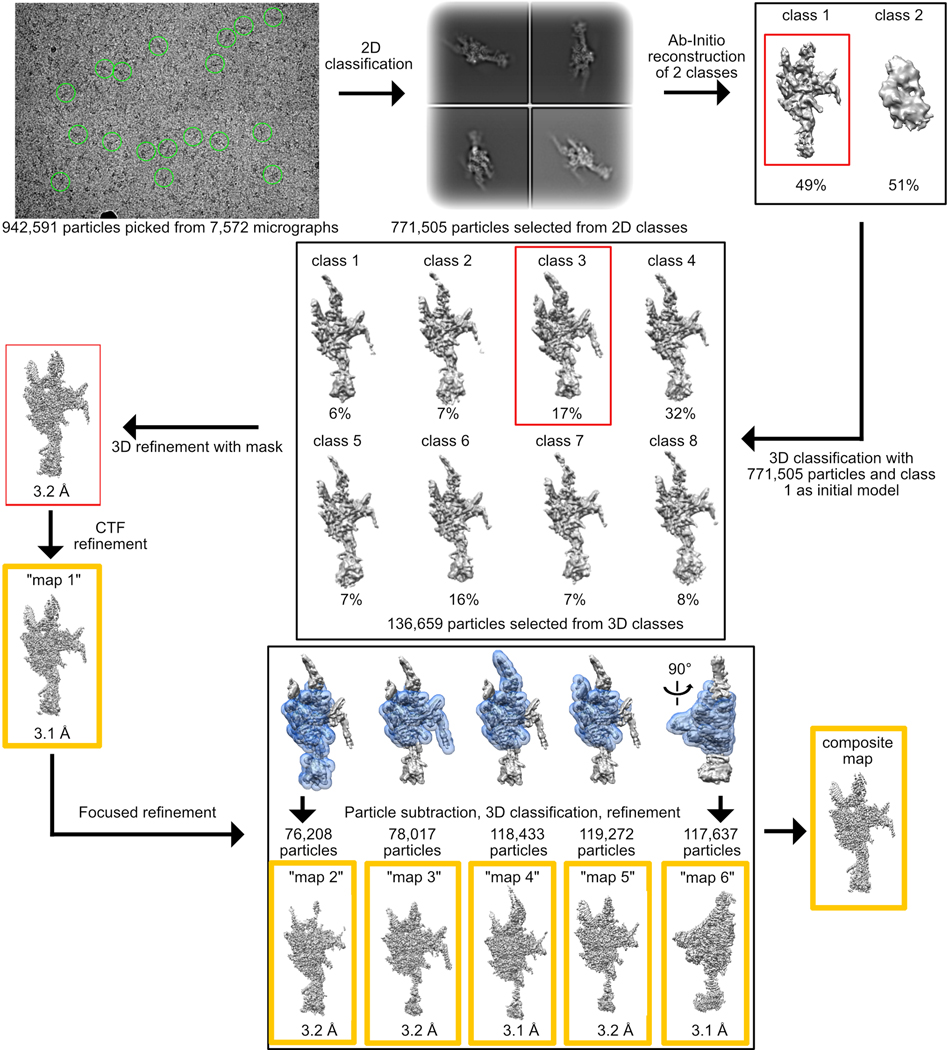
Workflow is summarized in Extended Data Fig. 1. Dose-fractionated super-resolution image stacks were motion corrected and Fourier binned by a factor of two using MotionCor256. Motion corrected sums with dose weighting were used for CTF determination using GCTF57. About 2,000 particles were manually picked with CryoSparc v2.958 and 2D classification yielded class averages that served as templates for automated particle picking. Out of 942,591 particles picked, 771,505 were selected after 2D classification and used to reconstruct ab initio 3D models. Two models were generated, each constructed from ~50% of the particles. The map that looked similar to the 2D class averages (class 1) was chosen for further processing. The 771,505 particles were transferred using UCSF Pyem59 to RELION 3.060, where rest of the processing was performed. Particles were subjected to 3D classification without alignment into 8 classes. The class at highest resolution, containing 136,659 particles (class 3), was refined using a custom mask to 3.2 Å. Till this step, data were processed with a pixel size of 0.8488 Å, based on a cross-grid calibration. Recently, the pixel size was re-calibrated to 0.835 Å based on experimental data. Thus, we performed CTF refinement twice – once to refine the spherical aberration correction and once for defocus using RELION 3.1, yielding a map at 3.1 Å. The density at the edges of the map was improved using focused-3D classification and refinement with 5 different masks that included the core and one of the four surrounding protrusions or neck (Extended Data Fig. 1). With each mask the region of interest was masked out and the projection of the rest of the map was subtracted. The same mask was used in 3D classification without alignment of the resulting particles into 3 classes. In each case, the class with the highest resolution and number of particles was chosen for 3D refinement (Extended Data Fig. 1). Maps were sharpened by applying a negative temperature factor estimated during post-processing, filtered to their estimated resolution, and re-scaled using a pixel size of 0.835 Å, resulting in “maps 1–6” (Extended Data Fig. 1 and Table 1). “Maps 1–6” were combined into a composite map using PHENIX61.
Cryo-EM data processing for the RS head minimal complex (“map 7”)
Workflow is summarized in Extended Data Fig. 5. Dose-fractionated super-resolution image stacks were motion corrected and Fourier binned by factors of 1.5 and 2 for the datasets collected on Arctica and Krios respectively, using MotionCor256. Motion corrected sums with dose weighting were used for contrast transfer function (CTF) determination using GCTF57. The dataset collected on the Arctica was processed using CryoSparc v2.5-v2.1258 as follows: ~3,000 particles were manually picked and subjected to 2D classification. The subsequent class averages were used as templates for automated particle picking, in which 643,913 particles were picked. Following 2D classification 352,859 particles were selected and used to reconstruct an ab-initio 3D map. Particles were similarly picked from the dataset collected on Krios. The resulting 799,383 particles selected after 2D classification were classified into three classes using the 3D model generated from the dataset collected on Arctica. Class 2, with the highest resolution and most particles, was selected for a second round of 3D classification into three classes. Class 3, containing 251,088 particles, was selected for 3D refinement. The map was refined with a mask to 3.02 Å using RELION 3.060. Further CTF refinement resulted in a map at an average resolution of 2.95 Å (“map 7”). This reconstruction was subjected to post-processing using a soft mask. The map was sharpened by applying a negative temperature factor of −50, estimated during post-processing, and filtered to its estimated resolution.
Overall resolutions for all maps (1–7) were estimated using the gold-standard Fourier Shell Correlation criterion (FSC=0.143). Local resolutions were estimated in RELION 3.0. Statistical information for the final density maps is presented in Table 1.
Model building
The model for the RS head minimal complex was constructed de novo in COOT62 using “map 7”. The model was fit into “map 1” of the RS head-neck complex using rigid body refinement and adjusted to the density of “map 1” in COOT. Models for RSP5, RSP1, RSP3, RSP2 and the N-termini of RSP4 and RSP6 were built de-novo using “maps 1–6”. A model for residues 3–160 of RSP23 was generated using Phyre263 and was modified according to the density in COOT. In some regions of the map, long stretches without characteristic side chain density made assignment of the sequence register challenging or impossible. In ambiguous regions where a plausible register could be assigned, we modeled the sequence explicitly though we cannot rule out a possible shift of 1–2 residues (Supplementary Table 2). In the most difficult regions, we built polyalanine segments. In these cases, there was high confidence in chain identity, but not in sequence, and thus, the poly-alanine stretches were assigned to a specific RSP, but with numbering outside of the protein amino-acid range (Supplementary Table 2). In the GAF domain of RSP2 an unknown density surrounded by the modeled protein was observed and was modeled with a short peptide (chain J), although it could belong to an unidentified metabolite. Three proteins present in the sample (RSP7, 11 and 16) were not modeled, either because they are sub-stoichiometric or not ordered in our reconstruction. The RS head minimal complex and RS head-neck complex were real-space refined against “map 7” and the composite map, respectively using PHENIX. The models were iteratively rebuilt in COOT and refined in PHENIX until completion. Model validation was performed with MolProbity64. Protein-protein interactions were analyzed with PISA65. Molecular graphics figures were prepared using UCSF Chimera66 and PyMOL (http://www.pymol.org). Consurf67 was used to color the model according to residue conservation (Extended Data Fig. 7c, d). The Dali server25 was used to compare RSP structures to existing structures in the wwPDB.
Thermal denaturation experiments
Wild-type or mutant RS head-neck complexes at a final concentration of 40 nM were incubated with SYPRO Orange 5000× (Thermofisher) diluted 1:250 in a 384-well qPCR plate (Axygen scientific) in 15 μL total volume in triplicate. A BioRad CFX384 qPCR System was used to collect fluorescence data with a temperature gradient of 1 min per 1°C from 25°C to 95°C. The first peak of the first derivative of fluorescence with respect to temperature was taken as the apparent denaturation temperature.
General maintenance of C. reinhradtii strains
The parental strain CC-5325 and an insertional mutant in RSP6 (CLiP ID: LMJ.RY0402.248886) from the Chlamydomonas Library Project (CLiP; https://www.chlamylibrary.org)32 were obtained from the Chlamydomonas resource center and maintained on Tris-Acetate-Phosphate (TAP) solid media (1.6% agar, USP grade, Thermo Fisher Scientific) with Hutner’s trace elements68 and 20 mg/mL paromomycin (Sigma). After isolation of single colonies and confirmation of the insertion site in the RSP6 mutant by PCR (Extended Data Fig. 9b), antibiotics was eliminated from the media. The resemblance in swimming phenotype of the CLiP RSP6 mutant and other reported RSP6 mutants33, as well as the ability to restore motility in the CLiP RSP6 by complementation with wild-type RSP6 (Fig. 6a–b and Extended Data Fig. 9d), were considered as indications that the examined swimming phenotype of the CLiP RSP6 mutant was largely due to disruption of the RSP6 gene. Prior to motility analysis cells were grown in liquid TAP under constant illumination.
Generation of RSP6-tagged strains
A double-stranded DNA fragment ordered from IDT containing a sequence encoding an HAx3 tag, preceded by an EcoRI restriction site, was inserted by Gibson assembly into the pBR9tagBFP plasmid69 (Chlamydomonas resource center) directly preceding the BamHI restriction site. The genomic sequence of RSP6 was amplified from genomic DNA extracted from strain CC-5325, and was inserted between the XhoI restriction site and the newly introduced EcoRI restriction site. The charge mutant strain was prepared on this template.
Liquid culture of the RSP6 insertional mutant (RSP6-deficient strain) mentioned above was grown in TAP medium to a density of 2–6*106 cells/mL. Cells were harvested by centrifugation at 3,000 x g for 5 min and gently resuspended in TAP supplemented with 40 mM sucrose at a density of 2*108 cells/mL. The cell suspension (40 μL) was transferred into a 0.4 cm gap electroporation cuvette with 5 μL sheared salmon sperm DNA (ambion) and 2 μg of plasmid DNA. Electroporation was performed using a NEPA21 electroporator (Nepagene) with the following parameters: Poring Pulse (300 V; length = 6 ms; interval = 50 ms; No. = 1; decay rate = 40%; + polarity), Transfer Pulse (20 V; length = 50 ms; interval = 50 ms; No. = 5; decay rate = 40%; + /- polarity). Electroporated cells were diluted into 8 mL TAP supplemented with 40 mM sucrose and allowed to recover overnight by gentle agitation in dim light. Transformants were isolated on TAP agar plates containing 10 μg/mL zeocin (Invitrogen). Colonies were streaked on TAP-zeocin agar plates and presence of tagged protein in the flagella was confirmed by immunofluorescence (IF).
Dual IF of axonemes
Chlamydomonas cultures grown overnight in liquid TAP media (200 μL) were allowed to adhere for ten minutes onto glass slides pre-treated with 0.1% poly-L-lysine (Sigma). Slides were then incubated twice with methanol at −20°C for 4 minutes, excess methanol was removed and slides were dried. Following blocking for 1 hour at RT with 10% goat serum (Sigma) in PBS, samples were incubated for 3–4 hours at RT with a monoclonal mouse anti-HA.11 antibody (BioLegend) diluted 1:200 and with a monoclonal rabbit anti-acetyl-α-tubulin antibody (Cell Signaling Technology) diluted 1:500. Slides were washed trice with PBS and incubated with secondary antibodies diluted 1:1000 for 1 hour at RT. Secondary antibodies used were Alexa Fluor 647 goat anti-rabbit IgG (H+L) and Alexa Fluor 488 goat anti-mouse IgG (Invitrogen). Slides were washed three times with PBS and Prolong Gold Antifade Reagent (Cell Signaling Technologies) was added to maintain samples until imaging. Images were acquired on a confocal Nikon Ti-Eclipse inverted microscope with a Nikon Plan Apo 100 × 1.40 oil immersion objective and an Andor iXon EM-CCD camera using μManager software package70.
Motility analysis of Chlamydomonas strains
For strains made in this study, two different clones with confirmed presence of tagged RSP6 in the flagella were analyzed. Cells were grown overnight to early logarithmic growth in liquid TAP media and imaged on a Nikon Eclipse TE 2000-E inverted microscope equipped with a Nikon dark-field oil condenser, a Nikon S Fluor 20 × 0.75 air objective and a red LED. Movies of 2,500 frames were recorded at a rate of 464 frames per second with a XiQ USB 3.0 superspeed camera (Ximea, model MQ013MG-ON). The plugin MTrack2 (https://imagej.net/MTrack2) was used to track cells in movies reduced to a frame rate of ~25 frames per second. For each clone 30–70 cells from at least three different glass slides were tracked. A measure for efficient swimming was calculated by dividing the path length of the cell (overall distance travelled) by its displacement (the shortest distance between the starting point and end point of the path). For beat frequency analysis, cells were tracked using MTrack2 in original movies (464 frames per second). For each track, the power spectra of the frame to frame displacement amplitude and displacement direction were multiplied to identify a peak that corresponds to average beat frequency. Statistical analysis was performed in Prism 7 (GraphPad, Inc). One-way ANOVA with Holm-Sidak test was used to determine statistical significance between strains.
Extended Data
Extended Data Fig. 1. Cryo-EM data processing workflow for the RS head-neck complex.
Overall schematic for 3D classification, masking and refinement is shown. Examples of picked particles are indicated with green circles on the micrograph. Masks used for focused refinement are shown in blue. Red boxes indicate the class that was chosen for the next step. Yellow boxes indicate maps used for model building and submitted to EMDB. See Online Methods for more details.
Extended Data Fig. 2. Overview of cryo-EM.
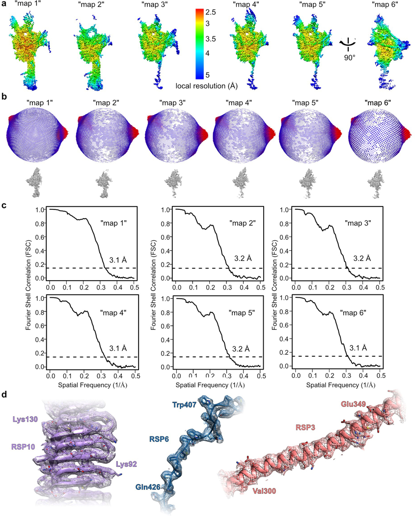
a, Density maps for the RS head-neck complex, colored by local resolution, estimated using RELION. b, Angular orientation distribution of all particles used in the final 3D reconstruction of each map. c, Fourier Shell Coefficient (FSC) curves measured by the Gold-standard method using RELION. d, Examples of density in various regions of the composite map for the RS head-neck complex.
Extended Data Fig. 3. Dimerization of the radial spoke head-neck complex.
Representative negative-stain EM class averages for the head- neck complex purified with a GST tag, cleaved (left), or retained (right). Box size is 4 nm.
Extended Data Fig. 4. Organization of the radial spoke head tetrameric core.
a, Topology diagram of the fold common to RSP9 and the middle domains of RSP4 and RSP6. The core of the fold is indicated with a grey background. Segments outside the core vary between the three proteins and are shown as they appear in RSP9. b, Three-dimensional structure of RSP9 colored according to the diagram in a. c, A helix-loop-helix motif found at the N-terminus of the RS head fold is used by all chains to dimerize with a neighboring subunit (RSP4 with RSP6 and RSP9 with itself, creating a homodimer). The RSP4- RSP6 dimer is shown as an example.
Extended Data Fig. 5. Structure of the radial spoke head minimal complex (RSP4, 6, 9 and 10).
a, Coomassie-stained SDS-PAGE of the recombinant RS head minimal complex. Uncropped gel image is shown in Supplementary Figure 1. b, Cryo-EM map (“map 7”) of the RS head minimal complex colored according to its constituent chains. c, Model built de novo for the RS head minimal complex according to the map in b. d, The positions of the RS head minimal complex within the head region of a C. reinhardtii RS subtomogram- averaged map in grey mesh (EMD-1941)8 are shown. e, Cryo-EM data processing workflow for 3D classification, masking and refinement is shown. Examples of picked particles are indicated with green circles on the micrograph. Red boxes indicate the class that was chosen for the next step. The yellow box indicates the map used for model building and submitted to EMDB. See Online Methods for more details. f, Cryo-EM map colored by local resolution, estimated using RELION. g, Angular orientation distribution of all particles used in the final 3D reconstruction of the map. h, Fourier Shell Coefficient (FSC) curve measured by the Gold- standard method using RELION. i, Alignment of the RS head core from our two models (RS head minimal complex (RSP4, 6, 9 and 10) colored; RS head-neck complex (grey) with an r.m.s.d. of 0.6 A, indicating the RS head tetrameric core is a rigid unit.
Extended Data Fig. 6. RSP5 supports the radial spoke head.
a, RS head surface (viewed from the CP as shown at the bottom left) highlighting the RSP2, 3 and 5 protrusions that are linked to the core through the GAF domain of RSP2 and through RSP5. b, RSP5 has an aldo-keto reductase (AKR) fold and an extra coiled-coil positioned at the head surface (dashed oval in a). c, Expression of the head-neck proteins except for RSP5 resulted in purification of two complexes as shown by the two SEC peaks. The peak eluting earlier from the column (1) contains primarily RSP2, 3 and 23, whereas the second peak contains primarily RSP1, RSP4, RSP6, RSP9 and RSP10, as shown at the bottom by Coomassie-stained SDS- PAGE. d, Each of the complexes in c was expressed and purified separately. Top, Coomassie-stained SDS-PAGE of a complex composed of RSP2, RSP3 and RSP23 purified on an anion-exchange column. The three proteins, corresponding to most of the neck, are shown on the right as they appear in the head-neck structure. Bottom, Coomassie-stained SDS-PAGE of a complex composed of RSP1, RSP4, RSP6, RSP9 and RSP10 purified on a SEC column. The five proteins, corresponding to the center of the RS head, are shown on the right as they appear in the head-neck structure. Uncropped gel images are shown in Supplementary Figure 1.
Extended Data Fig. 7. Characterization of recombinant RS head complexes with point mutations causing PCD.
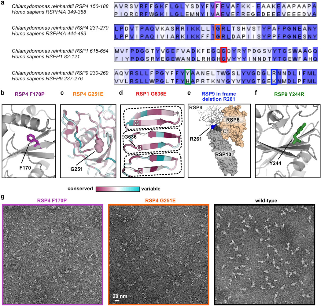
a, Sequence alignment of C. reinhardtii and human RSPs, showing the regions of PCD causal point-mutations (indicated with a colored box) are conserved. Residues are colored according to identity (identical - dark purple; positive - light purple). Alignment was done with T-Coffee30 and the figure was prepared in Jalview31. b-f, Amino acids in the Chlamydomonas RS head, corresponding to residues in human orthologs that when mutated cause PCD, are shown (Table 2). b, Phe170 (purple) is in the middle of a beta sheet in RSP4 (grey). When mutated to Pro it is expected to disrupt the sheet. c, A region from RSP4 colored according to residue conservation67, highlighting Gly251 (spheres) is conserved and buried between two loops. Mutation to Glu is expected to disrupt the loop arrangement. d, MORN repeats (dashed boxes) from RSP1 colored according to residue conservation67, indicating a conserved Gly residue in the same position for each repeat. Mutation of Gly636 to Glu is expected to disrupt the MORN repeat. e, The C’ terminal residues 262–269 in one copy of RSP9 (dark grey spheres) are positioned in a cleft created between RSP6 and RSP10 and thus in-frame deletion of the residue Arg261 (blue spheres) may affect the interaction between these three proteins. f, Tyr 244 (green) is on a beta strand in RSP9 (grey), interacting with a neighboring loop. g, Representative negative-stain EM micrographs for the RSP4 mutants, demonstrating the purified complexes are small and inhomogeneous. A micrograph of wild-type particles is shown for comparison.
Extended Data Fig. 8. Acidic loops compose the center of the radial spoke head surface.
a, Loops at the head surface shown in the top right (some were removed for clarity) were modeled into a clear density observed in the cryo-EM map (“map 1”), indicating the loops are structured. Asterisks indicate loops shown in b. b, Beta hairpins in RSP4 and RSP6, located at the head surface, are stabilized by hydrogen bonds (dashed lines). Residues that participate in these hydrogen bonds are indicated. c, Zoom into box in a, showing stabilizing lateral interactions (hydrogen bonds in dashed lines) between four different loops. The loops at the RS head surface are also supported by the tightly- packed folds that compose the RS head scaffold (Fig. 2). d, Electrostatic volume of the head surface generated in PyMol. Dashed red lines indicate regions not modeled, suggesting that the RS head surface is even more acidic than visualized by the electrostatic map. Number of missing residues and their percentage of D and E residues are listed on the right for each region.
Extended Data Fig. 9. Acidic loops in the RS head are important for efficient cilia motility.
a, Side view of the RS head, such that the CP is on the right. Acidic loops from RSP6 that point towards the CP, colored red and indicated with boxes, were chosen for mutagenesis. Boxes show a closer view of the residues mutated. b, PCR analyses of the Chlamydomonas RSP6-deficient strain (LMJ.RY0402.248886) that was used for genetic complementation, confirming the gene was disrupted by the insertion cassette. RSP6-specific primers (lane 1) amplified the genomic fragment in wild-type but not in the mutant. Cassette fragments on both ends (lanes 2 and 3) were amplified in the mutant, but not in wild-type. c, Immunofluorescence of HA tag and the flagellar marker acetylated tubulin in the RSP6- deficient strain (top), complemented with wild-type RSP6 (middle) and with the RSP6 charge-mutant (bottom). d, Average beat frequencies measured for Chlamydomonas wild-type cells (48±1 Hz; n=42), two clones of RSP6-deficient strain rescued with wild-type RSP6 (47±1 Hz; n=30 and 52±1 Hz; n=46), and two clones of the RSP6 charge mutant (44±1 Hz; n=42 and 41±2; n=39). Data are shown as means and s.e.m. Statistical significance was determined by a one-way ANOVA with Holm-Sidak test. ns denotes not significant, ***p<0.001; ****p<0.0001. Source data for graphs are available online. e, Mutations made in RSP6 acidic loops. Residues that differ from the wild-type sequence are in bold letters.
Supplementary Material
Acknowledgments
We thank Silvia Ramundo and Hiroaki Ishikawa for advice on handling C. reinhardtii strains, Taia Wu for assistance with thermal denaturation experiments and Damian Ekiert for advice on model building. We thank David Bulkley for assistance in the UCSF EM core facility. Some of this work was performed at the Simons Electron Microscopy Center and National Resource for Automated Molecular Microscopy located at the New York Structural Biology Center, supported by grants from the Simons Foundation (349247), NYSTAR, and the NIH National Institute of General Medical Sciences (GM103310). We thank Laura Yen, Hui Wei and Edward Eng for their assistance there. EM data processing has utilized computing resources at the HPC Facility at NYU, and we thank the HPC team for high performance computing support. We thank Lori Kohlstaedt form the Vincent J. Proteomics/Mass Spectrometry Laboratory at UC Berkeley, supported in part by NIH S10 Instrumentation Grant S10RR025622, for performing MS analysis. We are grateful to Vale lab members for discussions and critical reading of the manuscript, and to Nico Stuurman for assistance with Chlamydomonas swimming analysis. I.G.H. was supported by the Helen Hay Whitney foundation. G.B. funding: NIH/NIGMS R00GM112982; Damon Runyon Cancer Research Foundation DFS‐20‐16. R.D.V. funding: NIH R35GM118106.
Footnotes
Reporting Summary statement
Further information on experimental design is available in the Nature Research Reporting Summary linked to this article.
Data availability
The 3D cryo-EM density maps and atomic coordinates have been deposited in the Electron Microscopy Data Bank and wwPDB, respectively, under accession numbers EMD-22444 and PDB 7JR9 (minimal head complex); EMD-22446 and PDB 7JRJ (head-neck complex). Uncropped gel images are available in Supplementary Figure 1. Source data for Chlamydomonas swimming analysis are available online.
Competing interests
The authors declare no competing interests.
References
- 1.Satir P, Heuser T & Sale WS A Structural Basis for How Motile Cilia Beat. Bioscience 64, 1073–1083 (2014). [DOI] [PMC free article] [PubMed] [Google Scholar]
- 2.Zhou F & Roy S. SnapShot: motile cilia. Cell 162, 224 (2015). [DOI] [PubMed] [Google Scholar]
- 3.King SM Axonemal dynein arms. Cold Spring Harb. Perspect. Biol. 8, a028100 (2016). [DOI] [PMC free article] [PubMed] [Google Scholar]
- 4.Lin J & Nicastro D. Asymmetric distribution and spatial switching of dynein activity generates ciliary motility. Science 360 (2018). [DOI] [PMC free article] [PubMed] [Google Scholar]
- 5.King SM & Sale WS Fifty years of microtubule sliding in cilia. Mol. Biol. Cell 29, 698–701 (2018). [DOI] [PMC free article] [PubMed] [Google Scholar]
- 6.Viswanadha R, Sale W & Porter M. Ciliary Motility: Regulation of Axonemal Dynein Motors. Cold Spring Harb. Perspect. Biol. 9, a018325 (2017). [DOI] [PMC free article] [PubMed] [Google Scholar]
- 7.Smith EF Regulation of flagellar dynein by calcium and a role for an axonemal calmodulin and calmodulin-dependent kinase. Mol. Biol. Cell 13, 3303–3313 (2002). [DOI] [PMC free article] [PubMed] [Google Scholar]
- 8.Pigino G et al. Cryoelectron tomography of radial spokes in cilia and flagella. J. Cell Biol. 195, 673–687 (2011). [DOI] [PMC free article] [PubMed] [Google Scholar]
- 9.Barber CF, Heuser T, Carbajal-González BI, Botchkarev VV & Nicastro D. Three-dimensional structure of the radial spokes reveals heterogeneity and interactions with dyneins in Chlamydomonas flagella. Mol. Biol. Cell 23, 111–120 (2012). [DOI] [PMC free article] [PubMed] [Google Scholar]
- 10.Huang B, Piperno G, Ramanis Z & Luck DJL Radial spokes of Chlamydomonas flagella: Genetic analysis of assembly and function. J. Cell Biol. 88, 80–88 (1981). [DOI] [PMC free article] [PubMed] [Google Scholar]
- 11.Witman GB, Plummer J & Sander G. Chlamydomonas flagellar mutants lacking radial spokes and central tubules. Structure, composition, and function of specific axonemal components. J. Cell Biol. 76, 729–747 (1978). [DOI] [PMC free article] [PubMed] [Google Scholar]
- 12.Frommer A et al. Immunofluorescence analysis and diagnosis of primary ciliary dyskinesia with radial spoke defects. Am. J. Respir. Cell Mol. Biol. 53, 563–573 (2015). [DOI] [PMC free article] [PubMed] [Google Scholar]
- 13.Castleman VH et al. Mutations in radial spoke head protein genes RSPH9 and RSPH4A cause primary ciliary dyskinesia with central-microtubular-pair abnormalities. Am. J. Hum. Genet. 84, 197–209 (2008). [DOI] [PMC free article] [PubMed] [Google Scholar]
- 14.Kott E et al. Loss-of-function mutations in RSPH1 Cause primary ciliary dyskinesia with central-complex and radial-spoke defects. Am. J. Hum. Genet. 93, 561–570 (2013). [DOI] [PMC free article] [PubMed] [Google Scholar]
- 15.Jeanson L et al. RSPH3 Mutations Cause Primary Ciliary Dyskinesia with Central-Complex Defects and a Near Absence of Radial Spokes. Am. J. Hum. Genet. 97, 153–162 (2015). [DOI] [PMC free article] [PubMed] [Google Scholar]
- 16.El Khouri E et al. Mutations in DNAJB13, Encoding an HSP40 Family Member, Cause Primary Ciliary Dyskinesia and Male Infertility. Am. J. Hum. Genet. 99, 489–500 (2016). [DOI] [PMC free article] [PubMed] [Google Scholar]
- 17.Zhu X, Liu Y & Yang P. Radial Spokes — A Snapshot of the Motility. Cold Spring Harb. Perspect. Biol. 9, a028126 (2017). [DOI] [PMC free article] [PubMed] [Google Scholar]
- 18.Urbanska P et al. The CSC proteins FAP61 and FAP251 build the basal substructures of radial spoke 3 in cilia. Mol. Biol. Cell 26, 1463–1475 (2015). [DOI] [PMC free article] [PubMed] [Google Scholar]
- 19.Yang P et al. Radial spoke proteins of Chlamydomonas flagella. J. Cell Sci. 119, 1165–1174 (2006). [DOI] [PMC free article] [PubMed] [Google Scholar]
- 20.Piperno G, Huang B, Ramanis Z & Luck DJL Radial spokes of Chlamydomonas flagella: Polypeptide composition and phosphorylation of stalk components. J. Cell Biol. 88, 73–79 (1981). [DOI] [PMC free article] [PubMed] [Google Scholar]
- 21.Oda T, Yanagisawa H, Yagi T & Kikkawa M. Mechanosignaling between central apparatus and radial spokes controls axonemal dynein activity. J. Cell Biol. 204, 807–819 (2014). [DOI] [PMC free article] [PubMed] [Google Scholar]
- 22.Warner FD & Satir P. The Structural Basis of Ciliary Bend Formation. J. Cell Biol. 63, 35–63 (1974). [DOI] [PMC free article] [PubMed] [Google Scholar]
- 23.Sivadas P, Dienes JM, Maurice MS, Meek WD & Yang P. A flagellar A-kinase anchoring protein with two amphipathic helices forms a structural scaffold in the radial spoke complex. J. Cell Biol. 199, 639–651 (2012). [DOI] [PMC free article] [PubMed] [Google Scholar]
- 24.Kohno T, Wakabayashi K, Diener DR, Rosenbaum JL & Kamiya R. Subunit interactions within the Chlamydomonas flagellar spokehead. Cytoskeleton 68, 237–246 (2011). [DOI] [PMC free article] [PubMed] [Google Scholar]
- 25.Holm L. Benchmarking fold detection by DaliLite v.5. Bioinformatics 35, 5326–5327 (2019). [DOI] [PubMed] [Google Scholar]
- 26.Sajko S et al. Structures of three MORN repeat proteins and a re-evaluation of the proposed lipid-binding properties of MORN repeats. Preprint at 10.1101/826180 (2020). [DOI] [PMC free article] [PubMed] [Google Scholar]
- 27.Penning TM The aldo-keto reductases (AKRs): Overview. Chem. Biol. Interact. 234, 236–246 (2015). [DOI] [PMC free article] [PubMed] [Google Scholar]
- 28.Diener DR et al. Sequential assembly of flagellar radial spokes. Cytoskeleton 68, 389–400 (2011). [DOI] [PMC free article] [PubMed] [Google Scholar]
- 29.Gopal R, Foster KW & Yang P. The DPY-30 Domain and Its Flanking Sequence Mediate the Assembly and Modulation of Flagellar Radial Spoke Complexes. Mol. Cell. Biol. 32, 4012–4024 (2012). [DOI] [PMC free article] [PubMed] [Google Scholar]
- 30.Notredame C, Higgins DG & Heringa J. T-coffee: A novel method for fast and accurate multiple sequence alignment. J. Mol. Biol. 302, 205–217 (2000). [DOI] [PubMed] [Google Scholar]
- 31.Waterhouse AM, Procter JB, Martin DMA, Clamp M & Barton GJ Jalview Version 2--a multiple sequence alignment editor and analysis workbench. Bioinformatics 25, 1189–1191 (2009). [DOI] [PMC free article] [PubMed] [Google Scholar]
- 32.Li X et al. A genome-wide algal mutant library and functional screen identifies genes required for eukaryotic photosynthesis. Nat. Genet. 51, 627–635 (2019). [DOI] [PMC free article] [PubMed] [Google Scholar]
- 33.Wei M, Sivadas P, Owen HA, Mitchell DR & Yang P. Chlamydomonas mutants display reversible deficiencies in flagellar beating and axonemal assembly. Cytoskeleton 67, 71–80 (2010). [DOI] [PMC free article] [PubMed] [Google Scholar]
- 34.Ishikawa T Dyneins: Structure, Biology and Disease Ch. 6 (Academic Press; 2018). [Google Scholar]
- 35.Zhu X et al. The roles of a flagellar HSP40 ensuring rhythmic beating. Mol. Biol. Cell 30, 228–241 (2019). [DOI] [PMC free article] [PubMed] [Google Scholar]
- 36.Lin J et al. Cryo-electron tomography reveals ciliary defects underlying human RSPH1 primary ciliary dyskinesia. Nat. Commun. 5, 5727 (2014). [DOI] [PMC free article] [PubMed] [Google Scholar]
- 37.Abbasi F et al. RSPH6A is required for sperm flagellum formation and male fertility in mice. J. Cell Sci. 131 (2018). [DOI] [PMC free article] [PubMed] [Google Scholar]
- 38.Zheng W et al. Distinct architecture and composition of mouse axonemal radial spoke head revealed by cryo-EM. Preprint at 10.1101/867192 (2019). [DOI] [PMC free article] [PubMed] [Google Scholar]
- 39.Lindemann CB & Lesich KA Flagellar and ciliary beating: The proven and the possible. J. Cell Sci. 123, 519–528 (2010). [DOI] [PubMed] [Google Scholar]
- 40.Lindemann CB & Mitchell DR Evidence for axonemal distortion during the flagellar beat of Chlamydomonas. Cell Motil. Cytoskeleton 64, 580–589 (2007). [DOI] [PubMed] [Google Scholar]
- 41.Loreng TD & Smith EF The central apparatus of cilia and eukaryotic flagella. Cold Spring Harb. Perspect. Biol. 9, a028118 (2017). [DOI] [PMC free article] [PubMed] [Google Scholar]
- 42.Mitchell DR Orientation of the central pair complex during flagellar bend formation in Chlamydomonas. Cell Motil. 56, 120–129 (2003). [DOI] [PubMed] [Google Scholar]
- 43.Rupp G, O’Toole E & Porter ME The Chlamydomonas PF6 locus encodes a large alanine/proline-rich polypeptide that is required for assembly of a central pair projection and regulates flagellar motility. Mol. Biol. Cell 12, 739–751 (2001). [DOI] [PMC free article] [PubMed] [Google Scholar]
- 44.Dymek EE, Heuser T, Nicastro D & Smith EF The CSC is required for complete radial spoke assembly and wild-type ciliary motility. Mol. Biol. Cell 22, 2520–2531 (2011). [DOI] [PMC free article] [PubMed] [Google Scholar]
- 45.Heuser T, Dymek EE, Lin J, Smith EF & Nicastro D. The CSC connects three major axonemal complexes involved in dynein regulation. Mol. Biol. Cell 23, 3143–3155 (2012). [DOI] [PMC free article] [PubMed] [Google Scholar]
- 46.Gupta A, Diener DR, Sivadas P, Rosenbaum JL & Yang P. The versatile molecular complex component LC8 promotes several distinct steps of flagellar assembly. J. Cell Biol. 198, 115–126 (2012). [DOI] [PMC free article] [PubMed] [Google Scholar]
- 47.Weissmann F et al. biGBac enables rapid gene assembly for the expression of large multisubunit protein complexes. Proc. Natl. Acad. Sci. 113, E2564LP-E2569 (2016). [DOI] [PMC free article] [PubMed] [Google Scholar]
- 48.Zhang K et al. Cryo-EM reveals how human cytoplasmic dynein is auto-inhibited and activated. Cell 169, 1303–1314 (2017). [DOI] [PMC free article] [PubMed] [Google Scholar]
- 49.Washburn MP, Wolters D & Yates JR Large-scale analysis of the yeast proteome by multidimensional protein identification technology. Nat. Biotechnol. 19, 242–247 (2001). [DOI] [PubMed] [Google Scholar]
- 50.Xu T et al. ProLuCID, a fast and sensitive tandem mass spectra-based protein identification program. Mol. Cell. Proteomics 5, S174 (2006). [Google Scholar]
- 51.Cociorva D, L. Tabb D & Yates JR Validation of Tandem Mass Spectrometry Database Search Results Using DTASelect. Curr. Protoc. Bioinforma. 16, 13.4.1–13.4.14 (2006). [DOI] [PubMed] [Google Scholar]
- 52.Wang F et al. General and robust covalently linked graphene oxide affinity grids for high-resolution cryo-EM. Proc. Natl. Acad. Sci. Online version at 10.1073/pnas.2009707117 (2020). [DOI] [PMC free article] [PubMed] [Google Scholar]
- 53.Wang F et al. Amino and PEG-Amino Graphene Oxide Grids Enrich and Protect Samples for High-resolution Single Particle Cryo-electron Microscopy. J. Struct. Biol. 209, 107437 (2019). [DOI] [PMC free article] [PubMed] [Google Scholar]
- 54.Mastronarde DN Automated electron microscope tomography using robust prediction of specimen movements. J. Struct. Biol. 152, 36–51 (2005). [DOI] [PubMed] [Google Scholar]
- 55.Suloway C et al. Automated molecular microscopy: the new Leginon system. J. Struct. Biol. 151, 41–60 (2005). [DOI] [PubMed] [Google Scholar]
- 56.Zheng S et al. MotionCor2: anisotropic correction of beam-induced motion for improved single-particle electron cryo-microscopy. Nature Methods 14, 331–332 (2017). [DOI] [PMC free article] [PubMed] [Google Scholar]
- 57.Zhang K. Gctf: Real-time CTF determination and correction. J. Struct. Biol. 193, 1–12 (2016). [DOI] [PMC free article] [PubMed] [Google Scholar]
- 58.Punjani A, Rubinstein JL, Fleet DJ & Brubaker MA cryoSPARC: algorithms for rapid unsupervised cryo-EM structure determination. Nat. Methods 14, 290 (2017). [DOI] [PubMed] [Google Scholar]
- 59.Asarnow D, Palovcak E & Cheng Y UCSF pyem v0.5. Zenodo. https://github.com/asarnow/pyem (2019). [Google Scholar]
- 60.Scheres SHW A Bayesian view on cryo-EM structure determination. J. Mol. Biol. 415, 406–418 (2012). [DOI] [PMC free article] [PubMed] [Google Scholar]
- 61.Liebschner D et al. Macromolecular structure determination using X-rays, neutrons and electrons: recent developments in Phenix. Acta Crystallogr. Sect. D Struct. Biol. 75, 861–877 (2019). [DOI] [PMC free article] [PubMed] [Google Scholar]
- 62.Emsley P, Lohkamp B, Scott WG & Cowtan K. Features and development of Coot. Acta Crystallogr. Sect. D Biol. Crystallogr. 66, 486–501 (2010). [DOI] [PMC free article] [PubMed] [Google Scholar]
- 63.Kelley LA, Mezulis S, Yates CM, Wass MN & Sternberg MJE The Phyre2 web portal for protein modeling, prediction and analysis. Nat. Protoc. 10, 845–858 (2015). [DOI] [PMC free article] [PubMed] [Google Scholar]
- 64.Williams CJ et al. MolProbity: More and better reference data for improved all‐atom structure validation. Protein Sci. 27, 293–315 (2018). [DOI] [PMC free article] [PubMed] [Google Scholar]
- 65.Krissinel E & Henrick K. Protein interfaces, surfaces and assemblies service PISA at European Bioinformatics Institute. J. Mol. Biol. 372, 774–797 (2007). [DOI] [PubMed] [Google Scholar]
- 66.Pettersen EF et al. UCSF Chimera—a visualization system for exploratory research and analysis. J. Comput. Chem. 25, 1605–1612 (2004). [DOI] [PubMed] [Google Scholar]
- 67.Ashkenazy H et al. ConSurf 2016: an improved methodology to estimate and visualize evolutionary conservation in macromolecules. Nucleic Acids Res. 44, W344–W350 (2016). [DOI] [PMC free article] [PubMed] [Google Scholar]
- 68.Hutner SH, Provasoli L, Schatz A & Haskins CP Some approaches to the study of the role of metals in the metabolism of microorganisms. Proc. Am. Philos. Soc. 94, 152–170 (1950). [Google Scholar]
- 69.Rasala BA et al. Expanding the spectral palette of fluorescent proteins for the green microalga C hlamydomonas reinhardtii. Plant J. 74, 545–556 (2013). [DOI] [PubMed] [Google Scholar]
- 70.Stuurman N, Amdodaj N & Vale R. μManager: open source software for light microscope imaging. Micros. Today 15, 42–43 (2007). [Google Scholar]
Associated Data
This section collects any data citations, data availability statements, or supplementary materials included in this article.


