Abstract
Photoreduction of CO2 into value‐added fuels is one of the most promising strategies for tackling the energy crisis and mitigating the “greenhouse effect.” Recently, metal–organic frameworks (MOFs) have been widely investigated in the field of CO2 photoreduction owing to their high CO2 uptake and adjustable functional groups. The fundamental factors and state‐of‐the‐art advancements in MOFs for photocatalytic CO2 reduction are summarized from the critical perspectives of light absorption, carrier dynamics, adsorption/activation, and reaction on the surface of photocatalysts, which are the three main critical aspects for CO2 photoreduction and determine the overall photocatalytic efficiency. In view of the merits of porous materials, recent progress of three other types of porous materials are also briefly summarized, namely zeolite‐based, covalent–organic frameworks based (COFs‐based), and porous semiconductor or organic polymer based photocatalysts. The remarkable performance of these porous materials for solar‐driven CO2 reduction systems is highlighted. Finally, challenges and opportunities of porous materials for photocatalytic CO2 reduction are presented, aiming to provide a new viewpoint for improving the overall photocatalytic CO2 reduction efficiency with porous materials.
Keywords: CO 2 reduction, fuels, photocatalysis, porous materials, solar energy
Porous materials, including metal–organic frameworks, covalent organic frameworks, zeolites, and inorganic/organic porous semiconductors used for photocatalytic CO2 reduction are reviewed. Porous materials have been intensively exploited in solar‐driven CO2 reduction reactions for making valuable fuels. Three critical aspects of CO2 photoreduction are summarized and discussed, which provide new guidance for the future practical applications of porous materials.
1. Introduction
With excess consumption of fossil fuels, as presented in Figure 1a, the annual carbon dioxide (CO2) emission and global surface temperature are ever‐increasing rapidly, which indicates that the “greenhouse effect” will increase profoundly if such a consumption of fossil fuels continues.[ 1 , 2 , 3 ] There are two common strategies to mitigate the “greenhouse effect” through decreasing the concentration of CO2 in the atmosphere. One solution is sequestering CO2 in geological media through physical or chemical absorption. The other one is direct conversion of CO2 into valuable fuels, such as CO, HCOOH, methanol, methane, ethane, etc. Such an economic pathway can not only reduce the atmospheric CO2 concentration, but also provide significant chemical energy as substitutions to fossil fuels.[ 4 , 5 ] Up to now, several energy sources with a large diversity of technical routes have been proposed to convert CO2 into fuels, including thermochemical reduction, photochemical reduction, electrochemical reduction and biochemical reduction.[ 6 , 7 ] Of those, solar energy outweighs the others given its pollution‐free, inexhaustible, and cost‐free nature.[ 8 ] Hence, conversion of solar energy into chemical energy through photocatalytic CO2 reduction is worth of investigating.
Figure 1.
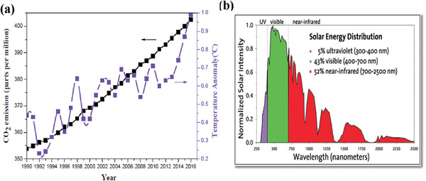
a) Annual CO2 emission in the atmosphere and global mean surface temperature as a function of years from 1990 to 2016.[ 1 ] b) UV–vis–IR sunlight spectrum. Reproduced with permission.[ 9 ] Copyright 2019, Wiley‐VCH.
A typical process of CO2 photoreduction involves three critical aspects. 1) Light absorption. Ultraviolet (UV) light accommodates high energy which readily excite photocatalysts, however, it only accounts for about 5% of the entire solar irradiance. Although inferred (IR) light accounts for more than a half, its low energy does not suffice to activate photocatalysts. Visible light, which accounts for about 43%, will be a sound and reliable source to be used for photocatalysis (Figure 1b).[ 9 ] To obtain high solar energy conversion efficiency, a large number of visible‐light responsive semiconductor materials have been investigated.[ 10 ] 2) Carrier dynamics include carrier separation, migration, trap, In general, light irradiation of a photocatalyst leads to the formation of photogenerated electron and hole pairs. Then they migrate toward the surface of the photocatalysts to participate in reduction and oxidation reactions, respectively.[ 11 ] 3) Adsorption and activation of CO2 molecules and reaction on the surface. In this process, CO2 molecules are expected to be adsorbed on the surface of photocatalyst. Therefore, the capacity of uptake CO2 is the key. Concentration of the adsorbed CO2 on the surface of a photocatalyst and number of activated catalytic sites determine the efficiency of CO2 reduction process.[ 12 ] In addition, some functional groups modified on the surface such as hydroxyl, amino, frustrated Lewis pairs (FLPs), could activate the adsorbed CO2 molecules and decrease the reaction energy barrier, which will boost the efficiency of CO2 reduction into fuels.[ 13 , 14 ] A large number of inorganic semiconductors have been developed as inspired by the pioneering work led by Fujishima and co‐workers in terms of employment of TiO2 for solar‐driven CO2 reduction in 1979.[ 15 , 16 ] In the recent years, significant advances have been achieved in expanding the visible‐light absorption range and facilitating solar energy conversion efficiency.[ 17 , 18 , 19 , 20 , 21 , 22 , 23 ] However, the performance of inorganic semiconductors remains unsatisfactory with respect to industrial applications, such as low capacity of CO2 absorption, limited specific surface area, large bandgap, electron–hole recombination in nonporous[ 24 ] and low photocatalytic CO2 reduction selectivity of high value‐added fuels. As such, it is of paramount significance to design and develop efficient and selective photocatalytic CO2 reduction systems with possession of extended visible‐light absorption ability, efficient photogenerated charge separation, excellent CO2 molecular adsorption capacity, and abundant active CO2 reduction sites.
In comparison with traditional porous/nonporous materials, metal–organic frameworks (MOFs), covalent–organic frameworks (COFs), and zeolites, recently have attracted considerable attention owing to low density, large surface area, high porosity, structural and compositional diversity, which holds great potential for a broad range of commercial aspects in physical, mechanical, acoustical, thermal, and electrical fields.[ 25 , 26 ] Benefiting from these specialties, porous materials have been widely applied in catalysts, sensors, gas adsorption and separation, drug delivery, and environmental governance.[ 27 , 28 , 29 , 30 , 31 , 32 , 33 , 34 , 35 , 36 , 37 , 38 ] In particular, solar‐driven CO2 reduction could be catalyzed by proper porous materials, owing to the tunable light absorption ability over broad range, the ameliorative carrier separation, the evenly distributed catalytic active site and the ideal catalytic platform for mechanism study of structure–activity relationships. In addition, the potential CO2 capture capability of porous materials further endows their merits toward photocatalytic reduction of CO2 into value‐added fuels by concentrating CO2 molecules at active sites.[ 39 ]
To make a comprehensive understanding of rational design and development of more creative porous materials for solar‐driven CO2 reduction, it is necessary to provide a timely research progress report to capture the state‐of‐the‐art progress in the field. Several reviews have focused on MOFs‐based materials from the perspectives of categories of photocatalytic products, wide applications such as water splitting and cycloaddition of CO2.[ 40 , 41 , 42 , 43 , 44 , 45 , 46 ] This report mainly summarized the state‐of‐the‐art progress of MOFs‐based photocatalytic systems for CO2 reduction; together with COFs‐based, zeolite‐based, inorganic porous semiconductors or organic polymers photocatalyst. In this report, we highlight representative approaches for optimizing the performance of CO2 photoreduction through using versatile porous materials and three main critical aspects will be discussed (Scheme 1 ). It includes the present fundamental of CO2 photoreduction and the recent four types of photoactive porous materials applied in CO2 reduction. Finally, challenges and prospects of porous materials for photocatalytic CO2 reduction are illustrated.
Scheme 1.
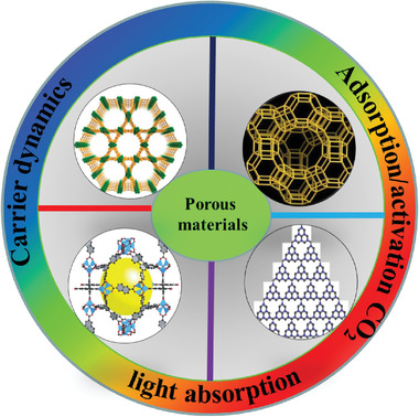
Photocatalytic CO2 reduction with porous materials.
2. Fundamentals of Porous Materials for CO2 Photoreduction
Photoreduction of CO2 into chemical feedstocks is a promising solution to energy crisis and environmental problems. A typical process of photocatalysis includes three basic but critical principles. As shown in Figure 2a, semiconductor adsorbs sunlight of energy ≥E g (bandgap) and generates electron–hole pairs simultaneously. Then photogenerated electrons transfer from valence band (VB) to conduction band (CB), leading to the separation of electron–hole pairs. Subsequently, the excited electrons and holes are transferred to the surface to take part in reduction reaction and oxidation reaction process, respectively. It is noted that CB potential of a semiconductor must satisfy the thermodynamic potential of different products. The main potentials of a range of CO2 reduction products are listed in Table 1 , which are referred the normal hydrogen electrode (NHE) at pH 7, namely E 0 V versus NHE at pH 7.[ 47 , 48 , 49 ]
Figure 2.
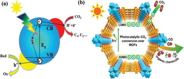
Schematic illustrations of a) photocatalysis over a semiconductor and b) photocatalytic CO2 reduction into organic chemicals over MOFs.[ 49 ] Reproduced with permission.[ 49 ] Copyright 2020, Elsevier.
Table 1.
Different products potentials with reference to NHE at pH 7
| Products | Reaction | E 0 (V vs NHE) | Equation |
|---|---|---|---|
| CO2 − | CO2 + e− → CO2 ·− | −1.90 | (1) |
| CO | CO2 + 2H+ + 2e− → CO + H2O | −0.53 | (2) |
| CH4 | CO2 + 8H+ + 8e− → CH4 + 2H2O | −0.24 | (3) |
| CH3OH | CO2 + 6H+ + 6e− → CH3OH + H2O | −0.38 | (4) |
| HCHO | CO2 + 4H+ + 4e− → HCHO + H2O | −0.48 | (5) |
| HCOOH | CO2 + 2H+ + 2e− → HCOOH | −0.61 | (6) |
| H2 | 2H+ + 2e− → H2 | −0.41 | (7) |
Porous materials exhibit a similar photocatalytic process to that of inorganic semiconductors. Taking MOFs as an example, compared with the inorganic semiconductors, the VB and CB of inorganic materials equal to the highest occupied molecular orbitals (HOMO) and the lowest unoccupied molecular orbitals (LUMO), respectively (Figure 2b). The following features make porous materials promising candidate for CO2 photoreduction:[ 50 , 51 ] i) High CO2 adsorption capacity makes the reaction site active to the adsorbed CO2 molecules, thus facilitates the performance of photocatalytic reduction of CO2. ii) The special porous structures have a pore confinement effect that will boost the catalysis process to a great degree. However, the performance of CO2 photoreduction still suffers low efficiency owing to three key aspects: insufficient utilization of visible‐light, negative electron–hole separation, and high inertness of active sites. Thus, in the next part, we summarize the existing strategies to improve the photocatalytic efficiency for CO2 reduction through tackling those three critical challenges.
3. Three Critical Aspects of MOFs‐Based Materials for CO2 Photoreduction
MOFs, a typical category of porous materials and built up with organic ligands and metal ions of clusters, have been extensively explored for CO2 photoreduction. Both the organic ligands and metal clusters can be a light harvest center owing to the metal complex like the inorganic semiconductor quantum dots (QDs), while the organic ligands can be considered antennae to harvest light.[ 52 , 53 ] Charge carrier separation and migration are vital for the reactions with the adsorbed molecules on the surface. Some sound strategies were introduced to ameliorate the charge carrier dynamics. Afterward, we discussed the correlation about the absorption of CO2 coupled with the activity of CO2 reduction.
3.1. Light Absorption
To expand the range of visible light absorption of MOFs materials, a number of strategies, such as amino‐modified, photosensitizer‐functionalized, electron‐rich conjugated linkers, post synthetic modifications (PSMs), and post synthesis exchange (PSE) were postulated. For metal clusters, metals were replaced with nonferrous ones or doping other ones to generate light harvest center.
3.1.1. Amino‐Functionalized CO2 Reduction Photocatalysts
Since Garcia and co‐workers reported the use of MOF‐5 as a semiconductor to play charge‐separation under light irradiation,[ 54 ] a number of publications regarding the semiconductor properties of MOFs have been explored.[ 55 , 56 , 57 ] However, most MOFs exhibit poor conductivity due to the mismatch between the orbitals of leaker and metal, resulting in a short transfer distance. As above‐mentioned, organic leaker acts as antennae and transfers the generated electrons to metal clusters, namely linker‐to‐metal cluster charge transfer (LMCT), which provides a short‐range transfer of photogenerated electrons. Therefore, it is crucial for the leaker to produce photogenerated electrons and thus provide sufficient electrons to participate the photocatalysis process.
NH2‐functionalized leakers could greatly widen the range of optical absorption. Li and co‐workers reported a visible light responsive NH2‐MIL‐125(Ti) by a substitution of ligands NH2‐BDC for BDC leaker of MIL‐125(Ti),[ 58 ] which broadens the absorption edge from 350 nm for MIL‐125(Ti) to 550 nm for NH2‐MIL‐125(Ti) (Figure 3a). The formate evolution rate of NH2‐MIL‐125(Ti) and MIL‐125(Ti) was 16.28, ≈0 µmol h−1 g−1, respectively (Figure 3b). Later, the same group also explored the visible light responsive of NH2‐UiO‐66 by substituting NH2‐BDC linkers for BDC linkers.[ 59 ] The absorption edge was increased to about 430 nm, which enhanced the photocatalytic activity (Figure 3c,d). It is noted that NH2‐UiO‐66(Zr) with mixed leakers even shows an improved formate generation rate. Obviously, (NH2)2‐BDC (DTA) partially replaces NH2‐BDC (ATA) in NH2‐UiO‐66(Zr) leading to enhancement in light absorption and CO2 absorption, which can improve the performance of photocatalytic reduction of CO2 with MOFs. Similarly, Wang et al. reported that all three NH2‐functionalized Fe‐based MOFs (NH2‐MIL‐101(Fe), NH2‐MIL‐53(Fe) and NH2‐MIL‐88B(Fe)) exhibited higher photocatalytic activity.[ 60 ] However, these cases differ from above mentioned MIL‐125 or UiO‐66 with −NH2‐free modification. The NH2‐free Fe‐based MOFs exhibit semiconductor likewise in the absence of LMCT and are able to produce formate form under visible‐light irradiation. Nevertheless, after −NH2 modification, not only the light absorption edges of these Fe‐based MOFs were extended to nearly 700 nm, but their flat band potentials became more negative than that of bare MOFs according to the Mott–Schottky analysis. The possible mechanism is that –NH2 acts a photoexcited center, which facilitates photogenerated electrons to transfer to Fe center other than the direct photoexcitation of Fe–O clusters (Figure 3e).
Figure 3.
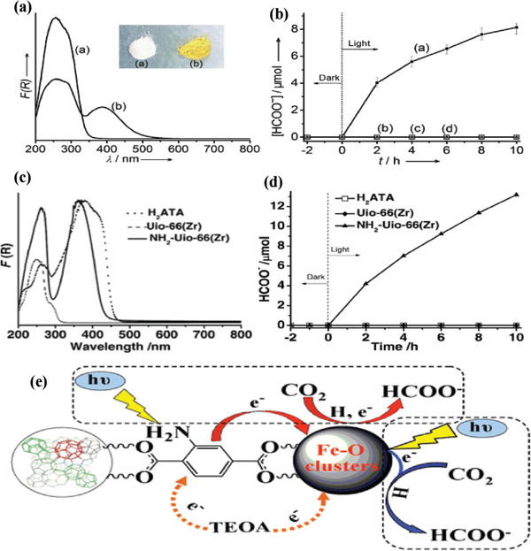
UV/vis spectra of a) MIL‐125(Ti) and b) NH2‐MIL‐125(Ti). The inset is the optical image of samples. b) Formate ion production rate of a) NH2‐MIL‐125(Ti) and b) MIL‐125. Reproduced with permission.[ 58 ] Copyright 2012, Wiley‐VCH. c) UV/vis spectra of H2ATA, UiO‐66(Zr), and NH2‐UiO‐66(Zr). d) The formate ion production rate of samples. Reproduced with permission.[ 59 ] Copyright 2013, Wiley‐VCH. e) Schematic illustration of Fe‐based MOFs for CO2 photoreduction. Reproduced with permission.[ 60 ] Copyright 2014, Wiley‐VCH.
Above‐mentioned studies demonstrate that NH2‐functionalized MOFs are a promising option to extend visible‐light range. However, most NH2‐functionalized MOFs exhibit light absorption limited to the range less than 550 nm. For instance, NH2‐MIL‐125(Ti)[ 58 ] and NH2‐UiO‐66(Zr)[ 59 ] expand the light absorption edge to nearly 550 and 450 nm, respectively. Therefore, some reports utilized conjugated molecules and amino groups together to further improve light responsive range of photocatalysts. By introducing functionalized conjugated ligand (H2L = 2,2′‐diamino‐4,4′‐stilbenedicarboxylic acid, H2SDCA‐NH2) into porous UiO‐type MOF, denoted as Zr‐SDCA‐NH2.[ 61 ] Zr‐SDCA‐NH2 illustrates a broad‐band absorption edge at about 600 nm, exhibiting a formate evolution rate of 96.2 µmol h−1 mmol MOF −1. This study provides a new platform for effectively improving light absorption of MOFs through employing molecular conjugation.
3.1.2. Electron‐Rich Conjugated Linkers CO2 Reduction Photocatalysts
Electron‐rich conjugated linkers can improve the CO2 absorption capacity, and increase the light response range.[ 62 , 63 ] Porphyrin‐based ligand (H2TCPP) is constructed from four pyrrole rings, exhibiting a near‐planar 18 π‐conjugated network, which may be beneficial for the porphyrin‐based material for CO2 capture and conversion. Robert and co‐workers[ 64 , 65 ] reported an iron tetraphenylporphyrin complex modified with four trimethylammonio groups, exhibiting excellent performance for converting CO2 to CO or CH4 and the mechanism was also proposed as depicted in Figure 4a. These investigations employed earth‐abundant Fe‐based materials with a cost‐effective nature. Similarly, Sadeghi et al. prepared a H2TCPP‐based MOF (Zn/PMOF) for the photocatalytic conversion of CO2 into CH4 in the presence of H2O vapor as a sacrificial agent.[ 66 ] The CH4 production rate was 8.7 µmol h−1 g−1 and no by product was detected.
Figure 4.
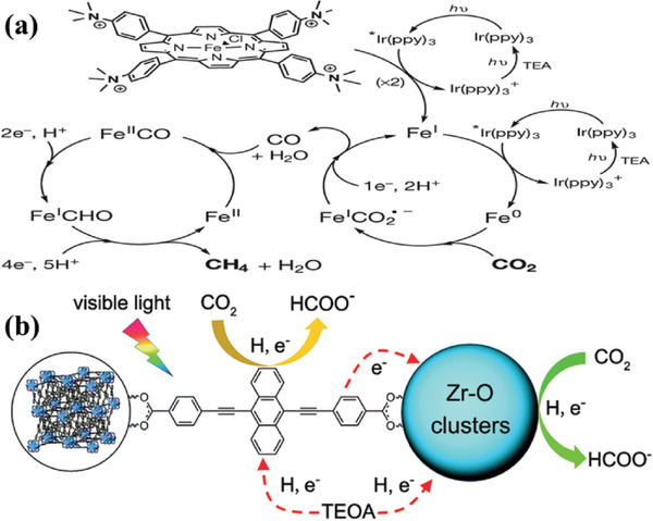
a) The mechanism for CO2 reduction to CH4 by catalyst. Reproduced with permission.[ 64 ] Copyright 2017, Nature publishing group. b) The mechanism of NNU‐28 for visible‐light‐driven reduction. Reproduced with permission.[ 67 ] Copyright 2016, Royal Society of Chemistry.
Anthracene‐based linker also exhibits excellent light absorption for electron‐rich conjugated structures. Su et al. reported that 4,4‐(anthracene‐9,10‐diylbis (ethyne‐2,1‐diyl)) dibenzoic acid reacts with ZrCl4 to form Zr‐MOF NNU‐28 ([Zr6O4(OH)4(L)6]·6DMF).[ 67 ] NNU‐28 displays the highest formate production rate of 52.8 µmol g−1 h−1 in terms of Zr‐MOFs, which is attributed to the role of anthracene‐based ligand. In comparison with the organic ligand of H2ATA, anthracene‐based ligand serves as an antenna for light harvesting and participates in CO2 reduction reaction by radical formation (Figure 4b). However, H2ATA ligand shows no other extra contribution to the reaction, which provides a novel way to design visible‐light responsive MOFs‐based photocatalysts. Huang and co‐workers[ 68 ] prepared porphyrin‐based Al‐PMOF coupled with Cu2+ and utilized it for photoreduction of CO2 into CH3OH, achieving high CH3OH formation rate of Al PMOF with Cu2+ (262.6 ppm g−1 h−1). This work provides a new strategy for designing efficient porphyrin‐based photocatalysts for capture and conversion of CO2 into liquid fuels.
3.1.3. Photosensitizer‐Functionalized CO2 Reduction Photocatalysts
In addition to ligands, photosensitizer can also be modified to improve the photoresponse range of catalysts. The introduction of photosensitizers (ReI(CO)3(bpy)X complexes with bpy = 2,2′‐bipyridine and X = halide) into MOFs could harvest light and reaction centers. In general, 2,2′‐bipyridine‐5,5′‐dicarboxylic acid (5,5′‐dcbpy), 2,2′‐bipyridine‐4,4′‐dicarboxylic acid (4,4′‐dcbpy) and bpy units are ideal linkers for building photosensitizers given their promising coordination ability, which is analogue to a BPDC leaker with transition metal carbonyl complexes. Recently, a large number of research groups are exploring photosensitizer‐functionalized MOFs as photocatalysts for CO2 reduction, such as Ru–MOF (Y[Ir(ppy)2(4,4′‐dcbpy)]2[OH]), Ir‐CP ({Cd2[Ru(4,4′‐dcbpy)3]·12H2O}n).[ 69 , 70 ] In 2011, Lin and co‐workers reported visible‐light responsive UiO‐67 applied in CO2 reduction under light irradiation through incorporating a photosensitizer of ReI(CO)3(bpy)Cl.[ 71 ]
However, CO evolution rate was relatively low even under the conditions of sacrificial agent of triethylamine (TEA). Later, they also reported photosensitizing metal–organic layers (MOLs) (Hf12‐Ru, based on Hf12 secondary building units (SBUs) and [Ru(bpy)3]2+ (bpy = 2,2′‐bipyridine) derived dicarboxylate ligands) as a new 2D material. Combining with photosensitizer M(bpy)(CO)3X (M = Re and X = Cl or M = Mn and X = Br), the complex exhibits efficient photocatalytic CO2 to CO[ 72 ] (Figure 5 ). These series of work demonstrate that incorporation of noble metal‐based photosensitizers into MOFs as building blocks is a sound approach for photocatalytic CO2 reduction.
Figure 5.
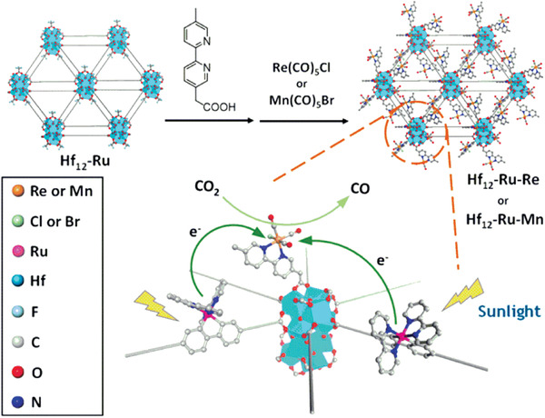
Schematic showing the synthesis of Ru‐Hf12‐M (M = Re or Mn) and the mechanism of photocatalytic CO2 reduction.[ 72 ] Reproduced with permission.[ 72 ] Copyright 2018, American Chemical Society.
3.1.4. Postsynthesis of Exchange (PSE) or Metal Doping CO2 Reduction Photocatalysts
Apart from functionalized organic ligands, it is possible to enhance visible‐light responsiveness and photocatalytic performance of MOFs via functionalization of metal centers. As mentioned before, metal clusters resemble inorganic semiconductor quantum dots and organic ligands play as antennae to harvest light. The methods of PSMs and PSEs represent typical doping methods in semiconductor‐based photocatalysts, which may generate doped level or provide active photocatalytic sites to improve the overall efficiency of photocatalysis.[ 73 , 74 ] In 2015, Li and co‐workers was the first to synthesize Ti‐doping NH2‐UiO‐66(Zr/Ti) by using PSE, which enhanced photocatalytic activity for CO2 reduction and hydrogen production under visible light irradiation.[ 75 ] As shown in Figure 6a, the UV–vis spectra of Ti‐doping indicate an enhanced visible light absorption at the wavelength of 400 to 600 nm, leading to a high formate evolution rate (Figure 6b). The possible mechanism is illustrated in Figure 6c. ATA generates photoelectrons under light irradiation, which are then transferred to Ti–Zr–O oxo–metal clusters. This work is the first example to improve photocatalytic performance by means of PSE, which provides a generic method to explore excellent MOF‐based photocatalysts. However, HCOO− evolution rate of Ti–Zr–O oxo–metal clusters needs further improvement compared pure NH2‐UiO‐66(Zr).
Figure 6.
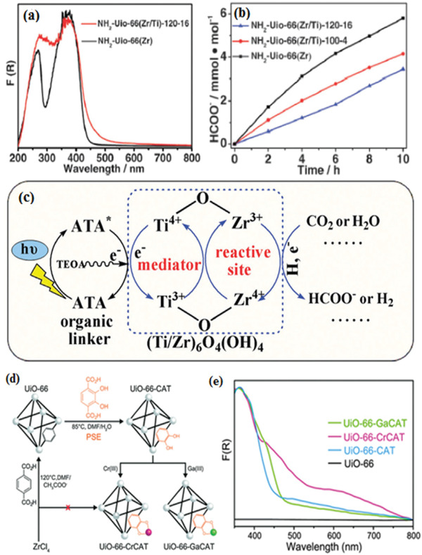
a) UV–vis spectra of the as‐prepared samples. b) The evolution rate of formate. c) Possible mechanism of Ti‐doping NH2‐UiO‐66(Zr/Ti). Reproduced with permission.[ 75 ] Copyright 2015, Royal Society of Chemistry. d) Preparation of MOF photocatalysts by PSE. e) UV–vis spectra of as‐prepared samples. Reproduced with permission.[ 76 ] Copyright 2015, Royal Society of Chemistry.
Pure UiO‐66(Zr) remains inactive for photocatalytic CO2 reduction up to date due to UV‐responsive and inefficient electrons transfer from leaker to metal clusters. In 2015, Cohen et al. [ 76 ] synthesized UiO‐66‐CAT (H2BDC replaced by 2,3‐dihydroxyterephthalic acid) and Cr‐monocatecholato species UiO‐66‐CrCAT, Cr‐monocatecholato species UiO‐66‐GaCAT through PSE (Figure 6d). The UV–vis spectra of the samples were shown in Figure 6e, UiO‐66‐CrACAT exhibited obvious visible light absorption because –OH increases HOMO level of H2BDC.[ 77 , 78 ] Photocatalytic performance reveals that UiO‐66‐CrACAT shows the highest formate evolution turnover number and presents a high stability. This work makes use of nonprecious metals (Cr) instead of noble metals (Ir, Pd) as dopants, providing a general way to develop more efficient catalysts.
3.2. Carrier Dynamics
The dynamics of charge carrier includes charge separation, migration, mobility, and diffusion length, which is one of the critical aspects in determining the efficiency of photocatalysis. In principle, photocatalytic reaction occurs only when photogenerated electrons are transferred to the surface. However, in many photocatalysts including porous materials or nonporous materials, the photogenerated electrons are recombination with holes. Only a small number of photoelectrons can participate in the process of photocatalysis. Therefore, it is extremely important to investigate the charge carrier dynamics. In this section, MOFs are coupled with other cocatalysts or semiconductors to form heterojunction or electron trapping sites, leading to efficient charge separation.
3.2.1. MOFs Coupled with Semiconductors as Photocatalysts
The acceleration of charge carrier separation and inhibition of harmful charge recombination is the key to improve the photocatalytic efficiency for photocatalytic CO2 reduction.[ 79 ] MOFs coupled with other materials may form heterojunction or electron capture sites in composite materials, which enable photogenerate electrons transfer from one part to another, leading to effective charge separation and improved catalytic activity.
In 2013, Liu et al. [ 80 ] first synthesized the composites of Zn2GeO4 and ZIF‐8 (zinc containing ZIFs) for efficient photocatalytic conversion of CO2 into liquid CH3OH, which is attributed to the efficiency carrier separation by forming heterojunction. Such a promising strategy is a key for investigating highly efficient photocatalysts to improve CO2 reduction efficiency by the virtue of excellent adsorption property of MOFs in aqueous media. After that, Wang and co‐workers systematically studied ZIF‐9 coupled with semiconductors such as CdS,[ 81 ] C3N4 [ 82 ] to ameliorate the charge transfer in the CO2 photoreduction process, which greatly improved the overall photocatalytic performance. Ye and co‐workers synthesized Co‐ZIF‐9/TiO2 nanocomposites for photocatalytic CO2 reduction.[ 83 ] The results of transmission electron microscopy (TEM), and X‐ray photoelectron spectroscopy (XPS) of the optimal sample show TiO2 and ZIF‐9 are very close with each other, leading to efficient separation of carrier. The highest photocurrent density of optimal further confirms the best carrier efficiency. This work presents that fabrication of Co‐ZIF‐9 with semiconductors to form a well‐designed structure is vital to further improve the performance of CO2 photoreduction.
Similarly, Li et al. prepared core–shell‐structured Cu3(BTC)2@TiO2 (BTC = 1,3,5‐benzenetricarboxylate) for photocatalyst in CO2 reduction.[ 84 ] It was designed for photocatalytic reduction of CO2 to CH4 in the presence of water, which also acts as sacrificial donor. In the composite photocatalyst, a large surface area of MOF plays as core and provides adsorption and photoconversion to CO2 molecules. Shell of the macroporous TiO2 is a semiconductor for supplying photogenerated electrons, which is easy to be excited by light and easy to diffuse in a MOF based core. In order to examine the carrier dynamics of the samples, ultrafast transient absorption (TAS) was carried out. As shown in Figure 7a,b, the electrons were transferred from TiO2 to the electrons trapping sites (Cu3(BTC)2) efficiently, leading to improvement in carrier separation.
Figure 7.
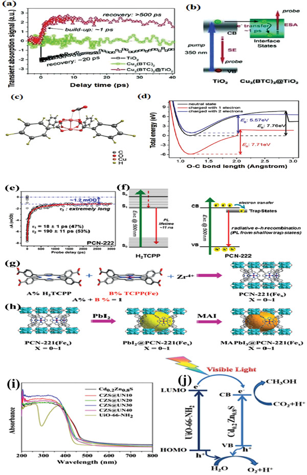
a) Ultrafast transient absorption and b) photoexcited dynamics. c) The optimized structure of a CO2 molecule adsorbed on Cu3(BTC)2. d) Change of band energy E B for CO2 reduction after the addition of one or two‐electron charge. Reproduced with permission.[ 84 ] Copyright 2014, Wiley‐VCH. e–f) TA spectra and carrier dynamics of H2TCPP, PCN‐222. Reproduced with permission.[ 86 ] Copyright 2015, American Chemical Society. g,h) Schematic illustrations of encapsulated MAPbI3@PCN‐221(Fex). Reproduced with permission.[ 87 ] Copyright 2019, Wiley‐VCH. i) UV–vis spectra of pure UiO‐66‐NH2, Cd0.2Zn0.8S, and CZS@UN composites. j) Schematic depict of charge carrier separation of composites for CO2 photoreduction. Reproduced with permission.[ 90 ] Copyright 2017, Elsevier.
Density functional theory (DFT) calculations presented that two photogenerated electrons transferred from TiO2 to Cu3(BTC)2, leading to high adsorption energy of CO2 and reducing E B from 7.76 eV for neutral state to 5.57 eV for charged with two electrons (Figure 7c,d), which facilitated the CO2 adsorption by Cu3(BTC)2. Similarly, Crakea et al. prepared TiO2/NH2‐UiO‐66 heterostructures via an in situ process.[ 85 ] The close contact between TiO2 and NH2‐UiO‐66 facilitated electron migration, and rendered high efficiency of electron hole separation. The efficient charge transfer was further confirmed by TAS spectroscopy.
Porphyrin‐based semiconducting MOF PCN‐222 was used in CO2 photoreduction for the first time in 2015,[ 86 ] exhibiting higher activity than that of H2TCPP leaker alone. As shown in Figure 7e,f, TA and photoluminescence spectra demonstrate that PCN‐222 has a long‐lived electron trap state, thus inhibits the electron–hole recombination and yields high efficiency of CO2 photoreduction. PCN‐222 exhibited much better activity than that of H2TCCP leaker alone. This work not only provides a new understanding of the carrier dynamics involved in MOFs, but also unveils the mechanism of charge‐carrier transfer. Recently, Zhang et al. reported a MAPbI3@PCN‐221(Fex) composite for CO2 photoreduction. As illustrated in Figure 7g,h, MAPbI3 was encapsulated in the pores of PCN‐221(Fex),[ 87 ] which is beneficial to the effective transfer of photogenerated electrons from the encapsulated MAPbI3 QDs to Fe catalytic sites, leading to high charge separation efficiency. This current study provides a method to improve the stability of lead halide perovskite QDs in aqueous atmosphere.
Transition metal sulfides (TMSs) were widely studied for photoreduction of CO2 in recent years owing to visible‐light responsiveness, low cost and satisfactory performance.[ 88 , 89 ] A series of nanocomposites were prepared by incorporating different contents of UiO‐66‐NH2 with solid‐solution Cd0.2Zn0.8S for photocatalytic CO2 reduction.[ 90 ] UV–vis spectrum reveals that the absorption edge of composites achieved slight red shift (Figure 7i), suggesting that composites are more responsive to sunlight. Of the as‐synthesized samples, an optimal composite (CZS@UN20, 20 wt% of UiO‐66‐NH2) exhibits the highest CH3OH evolution rate of 6.8 µmol h−1 g−1 under visible‐light irradiation, in which the CH3OH production rate of pure Cd0.2Zn0.8S is only 2.0 µmol h−1 g−1. The remarkable enhancement in performance was mainly attributed to efficient charge carrier separation (Figure 7j). With visible‐light irradiation, photogenerated electrons transferred from UiO‐66‐NH2 to Cd0.2Zn0.8S since the LUMO potential of UiO‐66‐NH2 was more negative than that of Cd0.2Zn0.8S, inhibiting the electron–hole recombination, thus achieved high activity of CO2 photoreduction. This work offers a promising candidate to practical applications. Therefore, the heterojunction composite materials formed by MOF and semiconductor materials can effectively separate photogenerated carriers. However, due to the inherent defects on the surface of inorganic semiconductor cannot be well grafted tightly with MOFs, many literatures used this method to greatly improve the efficiency of photogenerated charge separation which needed to be verified.
Using likewise doping method to synthesize the so‐called “multi‐metal‐site” catalysts, it is feasible to form doping energy levels in the metal cluster center, like inorganic semiconductors, which is not only conducive to light absorption, but also can provide the active site or acted as capture carrier center, so as to improve the overall efficiency of photocatalytic reduction of CO2. However, up to now, there is no in‐depth study at atomic level of polymetallic MOF to find out how the doping could generate defects in the structure, which is a hot spot in recent years but a difficult problem.
3.2.2. MOFs Coupled with Metal as Photocatalysts
Metal is utilized widely in photocatalysis as a light harvest center owing to their surface plasmon resonance (SPR) effect. Of those, double‐shelled plasmonic Ag–TiO2 hollow spheres are a good example for improving the activity of CO2 photoreduction.[ 91 ] Similarly, MOFs are a category of materials with porous structures that are elegant host matrices in confining versatile functional guest species, such as metal nanoparticles (MNPs), to yield enhanced photocatalytic performance through a synergistic effect.[ 92 ] A latest report by Yaghi and co‐workers presented such an attempt to the employment of MNPs/MOFs (Ag‐nanocubes‐MOF core–shell composites, Ag⊂Ren‐MOF) for photocatalytic reduction of CO2.[ 92 ] Re(CO)3(bpydc)Cl, a catalytic center, was attached to linkers to produce Re‐UiO‐67, followed by coating upon Ag nanocubes to yield Ag⊂Re‐UiO‐67 (Figure 8a,b). It is apparent that thickness of the Re complexes contributes greatly to the catalytic activity. As presented in Figure 8c,d, Re complexes with a thickness of 16 nm, i.e., Re3‐MOF‐16 nm, plays the highest photocatalytic activity. Moreover, Ag⊂Re3‐MOF‐16 nm retains the original SPR features, thus produces a strong electromagnetic filed to confine spatially photoactive Re metal sites in the shell, and consequently exhibits seven times higher enhancement in photocatalytic evolution activity of CO2‐to‐CO than that of Re‐UiO‐67 under visible‐light irradiation. This study shows that covalently attached active centers within interior MOFs can be spatially localized and increase their photocatalytic performance by electromagnetic field induced by plasmonic silver nanocubes.
Figure 8.
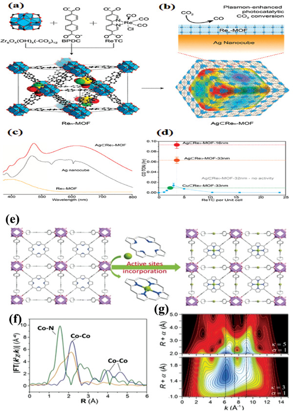
a) Zr6O4(OH)4(−CO2)12 secondary building units and the formation schematic of Ren‐MOF. b) Ren‐MOF coated on Ag nanocube. c) UV–vis spectra of Re3‐MOF, Ag nanocube, and Ag⊂Re3‐MOF. d) Photocatalytic CO2‐to‐CO conversion activity of Ren‐MOFs (blue line), Ag⊂Re0‐MOF, Cu⊂Re2‐MOF, and Ag⊂Re3‐MOFs with MOF thickness of 16 and 33 nm.[ 92 ] Reproduced with permission.[ 92 ] Copyright 2017, American Chemical Society. e) Schematic depicts of preparation of MOF‐525‐Co and f) Fourier transform magnitudes of the experimental Co K‐edge EXAFS spectra of samples. g) Wavelet transform for the k3‐weighted EXAFS signal of MOF‐525‐Co.[ 99 ] Reproduced with permission.[ 99 ] Copyright 2016, Wiley‐VCH.
In a following study, ultrafine Ag NPs were doped into Co‐ZIF‐9 (Ag@Co‐ZIF‐9) for photocatalytic reduction of CO2 to CO under visible light in the presence of a photosensitizer.[ 93 ] The photocatalytic performance of composites was enhanced twofold from that of Co‐ZIF‐9, demonstrating doping with MNPs was an efficient way to enhance photocatalytic efficiency of MOFs.
In addition, it is well recognized that the separation efficiency of charge carriers is an important factor to photocatalytic activity of semiconductor photocatalysts. When a Schottky barrier was formed at the junction of semiconductor and noble metal, photogenerated electrons in the semiconductor of a CB can be transferred to adjacent noble metal center, thus improving the separation of photogenerated carriers and ultimately improving the photocatalytic performance.[ 94 , 95 ] Therefore, doping precious metal, such as Pt and Au, into a semiconductor photocatalyst is a common method to suppress the recombination of photogenerated electrons and holes. Li and co‐workers[ 96 ] studied the effects of different metal‐doped M‐NH2‐MIL‐125(Ti) (M = Pt and Au) photocatalysts on CO2 reduction. Compared with pure NH2‐MIL‐125(Ti), Pt‐doped exhibited a higher formate evolution rate while Au‐doped exhibited lower formate production, indicating noble metal could influence the electron‐trapping, which further changed the products. Interestingly, Au‐NH2‐MIL‐125 imposed a negative effect on photocatalytic formate production. To elucidate the mechanism of different photocatalytic activities, ESR and DFT calculations for M‐NH2‐MIL‐125 were carried out. Results indicate hydrogen could spill over from Pt to Ti atoms, leading to the formation of Ti3+, which was considered as the active sites to produce formate. However, hydrogen spillover was difficult over Au‐NH2‐MIL‐125(Ti). Therefore, a negative effect on the photocatalytic formate generation was detected over Au‐NH2‐MIL‐125(Ti), indicating that the selection of an appropriate noble metal is key to the desired photocatalytic activity. This work illustrates that an effective Schottky barrier can be formed only if their Fermi band potential between noble metals and semiconductors are considered.
In addition to noble metal, nonprecious metal can also be incorporated with MOFs to photocatalytically reduce CO2 in an efficient manner. In recent years, atomically dispersed catalysts such as so‐called “single atoms anchored on matrix” which utilized maximum atom efficiency.[ 97 ] However, it is still challenging to fabricate practical and stable single atom catalysts owing to their high mobility in a catalytic process.[ 98 ] In this case, porous materials are a good candidate as matrix for providing coordination sites to anchor single metal atoms. Ye and co‐workers synthesized atomic Co dispersion of active sites in MOF‐525.[ 99 ] Co sites were incorporated into the porphyrin units to form MOF‐525‐Co and atomic Co was demonstrated by the Co K‐edge extended X‐ray absorption fine structure (EXAFS) and X‐ray absorption near‐edge structure (XANES) spectroscopy (Figure 8e–g). According to the energy transfer investigation coupled with the first principles calculation, photogenerated electrons could be effectively shifted to the reaction center Co “trap site,” which ameliorates charge separation, achieving CO evolution rate of 200.6 µmol g−1 h−1 and CH4 production rate of 36.67 µmol g−1 h−1, 3.13‐fold and 5.93‐fold from that of pure MOF. This work provides a strategy that could take advantages of the coordination feature of porous materials to design MOF‐based photocatalysts through efficient atomic doping for CO2 reduction.
3.3. Adsorption/Activation and Reaction with CO2
In general, a catalytic reaction requires the substrates adequately adsorbed on the surface of catalysts. Regarding photocatalytic CO2 reduction, adsorption of CO2 molecules on the surface of catalysts is a prerequisite owing to the low solubility of CO2 in most liquid solutions. As shown in Scheme 2 , three possible coordination structures of adsorbed CO2 on the surface of a catalyst were proposed. Firstly, oxygen of CO2 has a long pair of electrons that can coordinate with Lewis acid centers on the surface (Scheme 2a). Similarly, carbon in CO2 acted as Lewis acid that could donated to Lewis base centers on the surface (Scheme 2b). In the third type, oxygen and carbon are mixed coordinated with surface Lewis acid and Lewis base centers, respectively (Scheme 2c).[ 100 ] On one hand, MOF has multifunctional ligands that can be modified to form basic sites to activate inert CO2 molecules. On the other hand, MOFs possess high porosity, large surface area and tunable structure such as replaced acidic leaker by basic leaker to adsorb more CO2 molecules, thus facilitate photocatalysis. However, the concentration of CO2 in atmosphere is quite low and to capture CO2 from air will cost a lot of energy. Therefore, understanding how CO2 uptake capacity of porous materials affects their photocatalytic CO2 reduction is important for developing more efficient photocatalysts under low concentration of CO2. It will be practical in industrial if flue gas can be directly used as CO2 feedstocks.
Scheme 2.
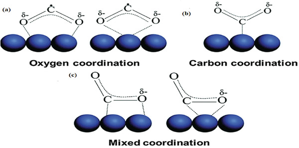
Three possible coordination ways of CO2 on the catalyst surface. a) Oxygen coordination, b) carbon coordination, and c) mixed coordination. Reproduced with permission.[ 100 ] Copyright 2016, Royal Society of Chemistry.
To understand the adsorption capacity of CO2 and activation of inert CO2 molecules, it is essential to unveil the relationships between the uptake capacity of CO2 and performance. For instance, RuII‐CO complex ([RuII(bpy)(terpy)(CO)](PF6)2) was synthesized using a PSE method with UiO‐67[ 101 ] (Figure 9a). As shown in Figure 9b, the photocatalytic activity decreases with decreasing partial pressure of CO2, indicating that the photocatalytic activity was highly dependent on the concentration of CO2. In contrast, catalytic performance of UiO‐67/RuCO is close to that measured under 5% CO2 atmosphere, which demonstrates that the composite could effectively adsorb CO2 in dilute concentrations and use of synergy between the adsorptive sites and the catalytic active sites.
Figure 9.
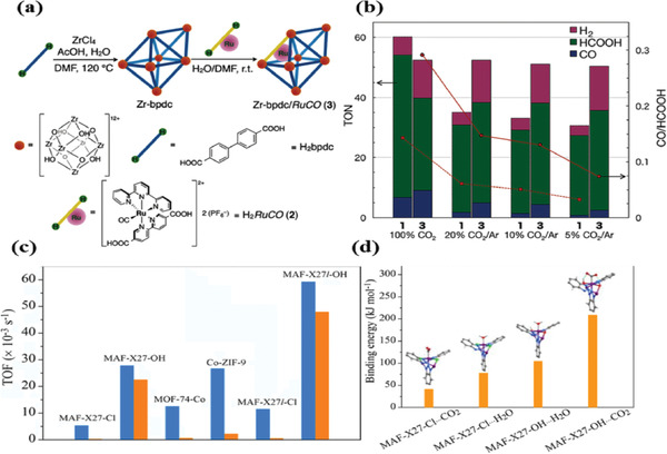
a) Synthesis of UiO‐67/RuCO, UiO‐67. b) The relationship between photocatalytic activity and CO2 pressure. Reproduced with permission.[ 101 ] Copyright 2016, Wiley‐VCH. c) TOF value under 0.1 atm of CO2. d) The binding structures and energies of MAF‐X27‐Cl and MAF‐X27‐OH. Reproduced with permission.[ 102 ] Copyright 2018, American Chemical Society.
Recently, three isostructural MOFs including MAF‐X27‐Cl, MAF‐X27‐OH, MOF‐74‐Co were used for CO2 photoreduction.[ 102 ] When the partial pressure was decreased to 0.1 atm, the photocatalytic activity of MAF‐X27‐Cl, MOF‐74‐Co decrease severely, while the MAF‐X27‐OH also exhibited a high CO TOF of 23 × 10−3 s−1 (28 × 10−3 s−1 at 1 atm). DFT simulations demonstrated that the m‐OH of MAF‐X27‐OH was coordinated with the open Co sites, which stabilized the Co–CO2 by hydrogen bonding, thus boosting the photocatalytic CO2 reduction (Figure 9c,d). Very recently, Wang and co‐workers synthesized UiO‐66/TiO2 composites[ 103 ] which displayed high yields of CH4 even at diluted CO2 condition (≤2%), though the detailed mechanism was not clear yet.
Although many works tried to convert CO2 at low concentrations, this filed is still at its early stage, suffering low durability and low selectivity of CO2 reduction. Considering that, Lin and co‐workers[ 39 ] synthesized a monolayer Ni MOFs, namely Ni MOLs, for photoreduction in diluted CO2, exhibiting CO generation rate of 12.5 µmol h−1, with a high CO selectivity of 97.8 %, much higher than that of Co MOLs (Figure 10a). To elucidate such a phenomenon, DFT calculations were carried out. As presented in Figure 10b, the active energy barrier COOH* formation over Co MOLs was slightly smaller than that of Ni MOLs, indicating that Co MOLs were more favorable to COOH* formation than Ni MOLs in kinetics, which was contrary to the performance results. As shown in Figure 10c, the adsorption energy of CO2 on Ni MOLs is −200.11 kJ mol−1, which was much stronger than that of the Co MOLs (−140.32 kJ mol−1). Therefore, DFT results clearly demonstrated that the initial adsorption of CO2 on MOLs was the crucial step of the reaction system. It was also validated that the selectivity of photocatalytic reduction of CO2 is directly correlated with the binding affinity of CO2 molecules.
Figure 10.
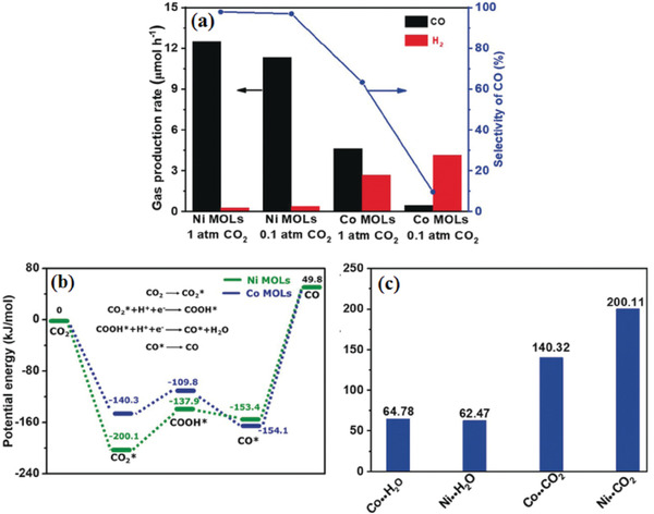
a) CO2 photoreduction activity of Ni MOLs and Co MOLs in pure CO2 and diluted CO2 (10 %). b) DFT calculation of active energy barrier of Ni MOLs and Co MOLs, respectively. c) CO2 and H2O adsorption energies of Ni MOLs and Co MOLs.[ 39 ] Reproduced with permission.[ 39 ] Copyright 2018, Wiley‐VCH.
Abovementioned relationships between CO2 uptake capacity of MOFs photocatalyst and performance of CO2 photoreduction are summarized as follows: Firstly, the activity of photocatalytic reaction is positively related to the concentration of CO2. Secondly, some functional groups or a high diversity of metals in MOFs may activate CO2 molecules and improve CO2 uptake such as hydrogen bonding, thus improve photocatalytic activity. Thirdly, MOF‐based materials combining with high CO2 adsorption energies of catalysts enable high catalytic activity even in a diluted CO2 atmosphere.
4. Recent Advances of Other Porous Materials for Photocatalytic CO2 Reduction
In addition to MOF, other porous materials such as COFs‐based, zeolite‐based and inorganic/organic porous semiconductors are also used for photocatalytic reactions.
4.1. COF‐Based Photocatalysts for CO2 Reduction
Yaghi and co‐workers first reported COF‐1 via self‐condensing with phenyl diboronic acid.[ 104 ] As a new class of porous material, COFs provide a versatile platform for CO2 photoreduction.[ 105 , 106 , 107 , 108 ] COFs are formed by periodic organic building blocks through covalent bonds. The establishment of spiropyrans (Ps) (i.e., extended π‐conjugation) promotes effective separation of charge carrier.
COFs have a well adjustable structure. Organic compounds are combined into the original counterpart to form a multifunctional COF photocatalyst with a dual function of redox and oxide. This kind of close connection way makes photogenerated charge transfer rapidly and reduces instability of photocatalysis to a certain extent. In recent years, there are many ligands modified to achieve effective separation of photogenerated charges.[ 109 , 110 ] Wisser et al.[ 111 ] reported using chromophores as light harvest antenna (controlling HOMO) and Cp*Rh as catalytic sites (regulating LUMO), which realize the rapid transfer of photogenerated charge. This kind of unique structure of long‐term stable perylene photosensitizer and the selective Rh‐based catalyst Cp*Rh@PerBpyCMP made it possible for photoreduction of CO2 in several days. The yield of formate was about 65 mmol gcat −1, which is the highest value obtained in heterogeneous photocatalysis. Wang and co‐workers[ 112 ] also reported a covalent triazine based framework (CTF) consisting of triphenylamine and triazine, which can be effectively used for photocatalytic reduction of CO2. The p‐conjugated structure provides a channel for the migration and separation of photoexcited electrons, which improves the photocatalytic activity. The self‐functionalized DA‐CTFs method not only improves the photocatalytic activity of organic semiconductors, but also cast new sights upon the fabrication of photocatalysts.
Su and co‐workers reported a pure TAPBB‐COF (synthesized with TAPP [5,10,15,20‐tetrakis(4‐aminophenyl)‐porphyrin] and 2,5‐dibromo‐1,4‐benzenedialdehyde) for CO2 photoreduction in presence of water and without any additional co‐reactants. By tuning the valence band of TAPBB‐COF, the photocatalyst achieved a high CO evolution rate of 295.2 µmol g−1.[ 113 ] This was the first work for photocatalytic CO2 reduction using COFs along without any sacrificial donor or co‐catalysts.
In comparison with pure COFs, metalized‐COFs forming hybrid metal–complex systems often exhibited higher performance. Lan and co‐workers synthesized the first metalized‐COFs photocatalyst for CO2 photoreduction.[ 114 ] As illustrated in Figure 11a, the as‐synthesized DQTP‐COF‐Co(2,6‐diaminoanthraquinone (DQ), (TP) 2,4,6‐triformylphloroglucinol) exhibited excellent CO2 reduction activity coupled with photosensitizer Ru(bpy)3Cl2 and triethanolamine (TEOA) providing electron and protons, resulting in a high CO formation rate of 1020 µmol g−1 h−1.
Figure 11.
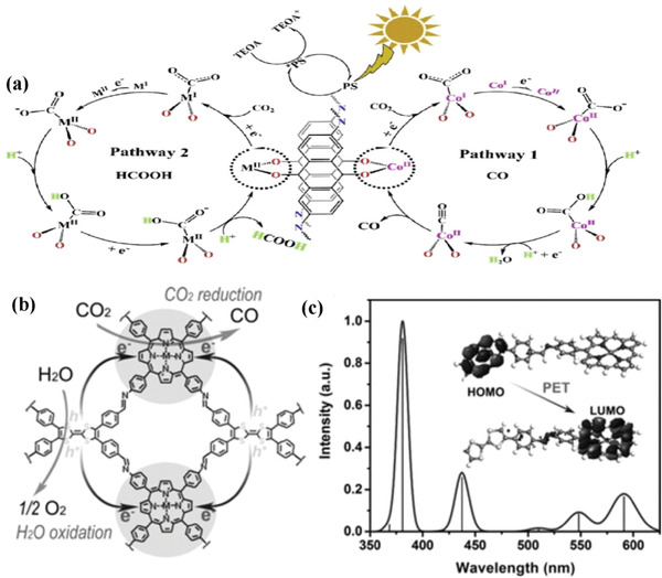
a) The photocatalytic schematic of DQTP‐COF‐M (M = Co, Zn). Reproduced with permission.[ 114 ] Copyright 2019, Elsevier. b) The mechanism of TTCOF‐M CO2RR with H2O oxidation. c) DFT simulation UV/vis DRS of TTCOF‐Zn and scheme of PET route under light excitation (inset). Reproduced with permission.[ 115 ] Copyright 2019, Wiley‐VCH.
Artificial photosynthesis is expected to use only H2O as electron sources in the absence of any additional sacrificial donor. To this end, Lan et al. developed a series of Z‐scheme porphyrin–tetrathiafulvalene COFs (TTCOF‐M, M = 2H, Zn, Ni, Cu) for photocatalytic CO2 reduction.[ 115 ] In that composite, electron‐deficient TAPP has good visible‐light harvesting ability.[ 116 ] Meanwhile, electron‐rich tetrathiafulvalene (TTF) has demonstrated to be an excellent electron donor.[ 117 ] Therefore, it is possible to combine TAPP and TTF to form a Z‐scheme (TAPP and TTF act on the reduction site and oxidation site, respectively) to transfer photogenerated electrons from TTF to TAPP under visible light irradiation, and effectively separate electron holes (Figure 11b,c). As expected, TTCOF‐Zn exhibited the highest CO evolution rate of 12.33 µmol after 60 h with nearly 100% selectivity and good stability. This is the first report of COF composites applied in the overall reaction of CO2 with H2O without any extra photosensitizer or sacrificial donor. However, the CO production rate surfers very slow. The possible reasons might be that the oxidation ability of TTF is relatively weak. Therefore, incorporated with much stronger oxidation ability material may be a good strategy for further improving photocatalytic performance.
Although many COFs were reported for CO2 photoreduction, it is still worth to concern that a large enough 2D COF single‐crystal is extremely difficult to be obtained. As a result, the actual structure of COFs is determined only by powder XRD and computational simulation, which limits the effective structure–activity relationship analysis of COFS.
4.2. Zeolite‐Based Photocatalysts for CO2 Reduction
Compared with traditional semiconductors, molecular sieves are intrinsic porous structure with high specific surface area and many active sites for photocatalysis.[ 118 , 119 ] Anpo et al. took the lead in investigating a series of Titanium oxides anchored within zeolites. The highly dispersed TiO2 within Y‐zeolite cavities (Ti‐oxide/zeolite) were synthesized by an ion‐exchange method, achieving high selectivity to produce CH4. The charge excited of the important intermediates (Ti3+‐O−)* are generated under UV irradiation. The generated electrons were trapped into H+ and CO2 to form H atoms and CO, then produced a series of carbon radicals. Finally, the reaction of these radicals produced CH3OH and CH4.[ 120 ] Next year, Ti‐MCM‐41 and Ti‐MCM‐48 were investigated in CO2 photoreduction.[ 121 ] Bai and co‐workers[ 122 ] first investigated using Ti‐MCM‐41 photocatalysts in monoethanolamine (MEA) solution for methane production. The optimal photocatalyst of Ti‐MCM‐41(50) (50 denote Si/Ti molar ratio of 50) exhibited CH4 yield of 62.42 µmol g−1 of cat after 8 h of UV irradiation. However, monoethanolamine was used as sacrificial agent, which was not environmentally and energy saving. Other than parent molecule severs, the zeolite‐based composites were also investigated in recent years. Cu–porphyrin impregnated mesoporous Ti‐MCM‐48 was investigated for the CO2 reduction under visible light irradiation, exhibiting methanol yield of 85.88 µmol g−1 L−1.[ 123 ] Yang and co‐workers investigated the Pt/MgO loaded Ti‐MCM‐41 zeolite with different Si/Ti molar ratios for photocatalytic CO2 reduction.[ 124 ] The electrons and holes were photogenerated in TiO4 tetrahedral units in molecular sieve under light irradiation, leading to form [Ti3+‐O−]∗ (Figure 12a). The high photocatalytic activity was achieved on Ti‐MCM‐41 because of synergistic effect. HZSM‐5 zeolites were used in CO2 photoreduction for the first time by Wang and co‐workers[ 125 ] [Fe3+–O2−] species could be excited by UV light to form an important intermediate, [Fe2+–O−]*, achieving high photocatalytic activity (Figure 12b). Very recently, Jing and co‐workers reported that composites of optimal Ag‐modified 2D/2D hydroxylated g‐C3N4/TS‐1 exhibited sevenfold than that of 2D TS‐1.[ 126 ] The enhanced photoactivity is attributed to the Z‐scheme mechanism between hCN and TS‐1, which greatly enhanced charge separation and extended range of visible‐light absorption. This work presented a feasible design strategy to synthesize high efficiency TS‐1 zeolite‐based photocatalyst.
Figure 12.
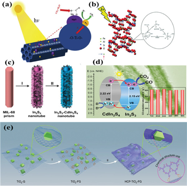
a) The proposed mechanism of CO2 reduction of Ti‐MCM‐41. Reproduced with permission.[ 125 ] Copyright 2019, Elsevier. b) The possible mechanism of CO2 reduction of HZSM‐5. Reproduced with permission.[ 126 ] Copyright 2016, Royal Society of Chemistry. c) Schematic illustration of the synthesis of In2S3‐CdIn2S4 heterostructured nanocube and d) its band structure and recyclability for photocatalytic CO2 reduction. Reproduced with permission.[ 147 ] Copyright 2017, American Chemical Society. e) Construction of a well‐defined porous HCP‐TiO2‐FG composite structure. Reproduced with permission.[ 149 ] Copyright 2019, Nature Publishing Group.
Although many zeolites have been used in photocatalytic CO2 reduction, there are still many problems to be solved. For example, structure–activity relationship is still unclear. The overall yield is still very low. Much more novel molecular sieves need to be developed for photoreduction of CO2.
4.3. Inorganic/Organic Porous Semiconductors
In addition to the classic porous materials for the CO2 photoreduction, inorganic/organic porous materials were also discussed in this section.[ 127 , 128 , 129 , 130 , 131 , 132 ] For the CO2 reduction, an efficient photocatalyst should possess high uptake capacity of CO2. Therefore, porous carbon materials, porous metal oxides, are discussed in this section. Wang et al. [ 133 ] synthesized hybrid carbon@TiO2 hollow sphere by utilizing a template of a carbon nanosphere. The optimal composites exhibited CH4 evolution rate of 4.2 µmol g−1 h−1 and CH3OH production rate of 4.2 µmol g−1 h−1. The enhanced photoactivity was attributed to the increased CO2 uptake (0.64 mmol g−1) and specific surface area (110 m2 g−1), together with enhancement light absorption due to the multiple reflections. When utilize water as electron sacrificial agent, hydrogen production is the main competitive reaction in the process of CO2 reduction.[ 134 , 135 ] In order to improve the selectivity of CO2 reduction under the existence of water, covering a carbon layer on the photocatalyst will make more protons to participate in CO2 reduction. In this case, Pan et al. [ 136 ] reported wrapped a 5 nm thick carbon layer outside the In2O3, exhibited photoactivity of CO and CH4 evolution rate of 126.6 and 27.9 µmol h−1, respectively. The greatly enhancement performance was attributed to the improved chemisorption of CO2, which increased the chance of proton capture by the CO2 −. In addition, Organic porous polymers such as C3N4, polymer and BN have been also explored in recent years.[ 137 , 138 ] Yu and co‐workers[ 139 ] synthesized hierarchical porous O‐doped g‐C3N4 by heating, exfoliating, and curling‐condensation of bulk g‐C3N4. The methanol evolution rate is 0.88 µmol g−1 h−1, fivefold higher than that of bulk g‐C3N4 (0.17 µmol g−1 h−1). The greatly enhanced photoactivity was mainly resulted from the porous g‐C3N4 with higher specific surface area, enhanced light absorption, together with more exposed active edges. This work paves a novel way to design hierarchical porous nanostructures. However, the photocatalytic evolution rate needs to be improved.
Inorganic porous semiconductor ZnO was investigated by Long and co‐workers[ 140 ] ZnO forms 3D holes at high temperature, so that metal particles can be fixed to ZnO in the subsequent synthesis process, and this can make the metal particles evenly distributed. Utilization of the surface plasmon resonance (SPR) of noble metals, the as‐prepared samples exhibited high yield of CH4 and CO. Similarly, He and co‐workers investigated the effect of defects in porous ZnO nanoplate on CO2 photoreduction.[ 141 ] In this work, defects in the porous ZnO accelerate separation of photogenerated carriers, resulting in greatly enhanced photocatalytic performance. However, the stability and photoactivity of the photocatalyst are desirable to improve. Furthermore, intermediate species for the CO2 photoreduction on defective ZnO should be deep investigated. Chromium (Cr) doped mesoporous CeO2 was synthesized via a nanocasting route.[ 142 ] The mesoporous structure could enhance the uptake capacity of CO2, leading to high photocatalytic activity. However, it is still a challenge to synthesize porous inorganic semiconductors directly due to its inflexible tunability in structure. In the past few years, many porous semiconductors were derived from heating MOFs due to its intrinsic porous structure.[ 143 , 144 , 145 ] Li and co‐workers first reported the porous hierarchical TiO2 derived from MIL‐125(Ti) for photocatalytic CO2 reduction.[ 146 ] TiO2 with high surface area modified with basic MgO, leading to high photocatalytic CO2 reduction activity. Lou et al. synthesized a series of compounds with hierarchical structure such as In2S3‐CdIn2S4 (Figure 12c,d) and sandwich‐like ZnIn2S4‐In2O3 based on MIL‐68 as precursor. The hierarchical structure is benefit to light absorption through light scatting and reflection, reduce the free path of carrier diffusion, increase the reaction contact area with CO2, thus greatly improves the efficiency of CO2 photoreduction.[ 147 , 148 ] Wang et al.[ 149 ] synthesized porous polymer‐TiO2‐graphene (HCP‐TiO2‐FG) photocatalyst for the conversion of CO2 under visible light irradiation (Figure 12e). This composite, with large surface area 988 m2 g−1 and CO2 uptake capacity due to its porous structure, exhibited high CH4 formation rate of 27.62 µmol g−1 h−1 without any sacrificial reagents or co‐catalysts. This work provided a prototype of the combination of microporous organic polymers used in CO2 photoreduction.
4.4. Comparison between Four Kinds of Porous Materials
Photocatalyst with high CO2 uptake is a necessary condition for catalytic CO2 conversion. Porous materials such as MOFs, COFs, molecule sieve and inorganic/organic porous materials have attracted considerable attentions in the CO2 conversion field due to their high specific surface area and well‐tailor structure.[ 25 ] However, each kind of porous material has its advantages and disadvantages. For instance, MOFs exhibited large surface area and flexible tunability structure compared with inorganic porous materials but suffered poor water resistance. On the other hand, the inorganic porous material is so hardly decorated that it so difficult to study the structure–activity. With regard to the molecule sieves, they possess uniform pore size, definite skeleton structure. However, just as MOFs, molecule sieves also suffer poor water resistance and unsuitable for high pressure adsorption. In recent years, COFs have attracted considerable attentions because of adjustable structure. However, the synthesis method is too complex and involves many organic compounds compared with inorganic porous material, which is not environmentally friendly. The advantages and disadvantages of different porous materials are summarized in Scheme 3 .
Scheme 3.
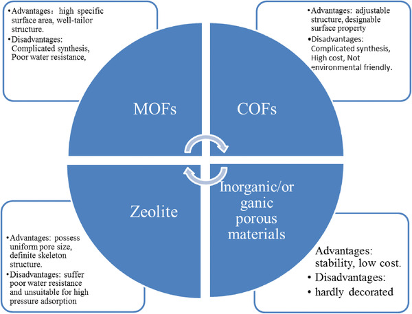
The advantages and disadvantages of four kinds of porous materials.
5. Conclusions and Perspectives
The development of porous materials with high catalytic efficiency is an important research area given their diverse chemical structures and multitudinous applications (Table 2 ). This progress report summarizes the recent advances in MOFs‐based materials for photocatalytic CO2 reduction from three critical photocatalytic aspects, say light absorption, carrier dynamics, and relationship between CO2 uptake capacity and activity. Owing to their intrinsic porosity and smooth implementation of function moieties, the catalytic performance can be improved fundamentally. As highlighted above, porous materials can be used as solid state photocatalysts that will harvest visible light and provide active catalytic centers simultaneously within a single structure. Their CO2 reduction performance can be enhanced by either tuning the building blocks for more efficient light absorber, adjusting the metal centers to improve adsorption capacity and catalytic activity, or a conjunction of both. In addition, a large number of porous materials allow them to couple with molecular catalysts, photosensitizer molecules, semiconductors or plasmonic metal clusters, thereby yielding novel, high surface area composite photocatalysts to present a higher catalytic activity. In particular, most porous materials have potential for CO2 capture capacities, which may promote their applications at low CO2 concentration conditions. Above all, porous materials hold their unique advantages in solar‐driven CO2 reduction and all the synthetic strategies will offer the rational design of porous material‐based photocatalysts with excellent catalytic performance.
Table 2.
Porous material‐based for photocatalytic CO2 reduction. TEOA: triethanolamine, TEA: triethanolamine, TON: turnover number
| Photocatalysts | Reaction medium | Major product | Max rate evolution | Ref. |
|---|---|---|---|---|
| NH2‐MIL‐125(Ti) | MeCN/TEOA (5:1) | HCOO− | 8.14 µmol, 10 h | [ 58 ] |
| NH2‐UiO‐66(Zr) | MeCN/TEOA (5:1) | HCOO− | 13.2 µmol, 10 h | [ 59 ] |
| Zr‐SDCA‐NH2 | MeCN/TEOA (30:1) | HCOOH | 96.2 µmol h−1 mmol MOF −1 | [ 61 ] |
| Zn/PMOF | Water (vapor) | CH4 | 8.7 µmol h−1 g−1 | [ 66 ] |
| NNU‐28 | MeCN/TEOA (30:1) | HCOOH | 52.8 µmol g−1 h−1 | [ 67 ] |
| Al‐PMOF | 100 mL water + 1 mL TEA | CH3OH | 262.6 ppm g−1 h−1 | [ 68 ] |
| UiO‐67/ReI(dcbpy) (CO)3Cl | MeCN/TEA = 20:1 | CO | TON = 10.9 | [ 71 ] |
| Hf12‐Ru‐Re/[Ru(bpy)3]2+ | 1.9 mL CH3CN + 0.1 mL TEOA | CO | TON = 3849 | [ 72 ] |
| NH2‐UiO‐66(Zr/Ti) | MeCN/TEOA (5:1) | HCOO− | 5.8 mmol mol−1 | [ 75 ] |
| UiO‐66‐CrCAT | MeCN/TEOA (4:1) | HCOOH | 51.73 µmol, 6 h | 76] |
| ZIF‐8/Zn2GeO4 | Na2SO3 | CH3OH | 2.44 µmol g−1 | [ 80 ] |
| Co‐ZIF/g‐C3N4 |
MeCN:H2O = 3 : 2 TEOA = 1 mL |
CO | 20.8 µmol CO, 2 h | [ 81 ] |
| Co‐ZIF‐9/CdS |
MeCN:H2O = 3 : 2 TEOA = 1 mL |
CO | 85.6 µmol, 3 h | [ 82 ] |
| Co‐ZIF‐9/TiO2 | 3 mL water | CO | 8.79 µmol, 10 h | [ 83 ] |
| Cu3(BTC)2@TiO2 | Water (vapor) | CH4 | 2.64 µmol g−1 h−1 | [ 84 ] |
| NH2‐UiO‐66/TiO2 | CO2/H2 (1.5 v/v ratio) | CO | About 5 µmol g−1 h−1 | [ 85 ] |
| PCN‐222 | MeCN/TEOA (10:1) | HCOO− | 30 µmol, 10 h | [ 86 ] |
| MAPbI3@PCN‐221(Fe0.2) | MeCN/TEOA (v/v, 1:0.012) | CH4 | 1028.94 µmol g−1 | [ 87 ] |
| Cd0.2Zn0.8S@UiO‐66‐NH2 | 100 mL 0.1 m NaOH | CH3OH | 6.8 µmol h−1 g−1 | [ 90 ] |
| Ag⊂Re3‐MOF‐16 nm | MeCN/TEOA (20:1) | CO | TON ≈ 0.1 | [ 92 ] |
| Ag@Co‐ZIF‐9 | MeCN/TEOA/H2O = 4:1:1 (v/v) | CO | 28.4 µmol, 0.5 h | [ 93 ] |
| Pt/NH2‐MIL‐125(Ti) | MeCN/TEOA (5:1) | HCOOH | 12.96 µmol, 8 h | [ 96 ] |
| MOF‐525‐Co | MeCN/TEOA (4:1) | CO | 200.6 µmol g−1 h−1 | [ 99 ] |
| Ni MOLs | MeCN/TEOA/H2O = 3:1:2 (v/v) | CO | 12.5 µmol h−1 | [ 39 ] |
| DA‐CTF | MeCN/TEOA (2:1) | CO | 9.3 µmol, 2 h | [ 112 ] |
| TAPBB‐COF | 1 mL Water | CO | 295.2 µmol g−1 | [ 113 ] |
| DQTP COF‐Co/Zn | MeCN/TEOA = 4:1 | CO | 1.020 µmol h−1 g−1 | [ 114 ] |
| TTCOF‐Zn | Water | CO | 12.33 µmol, 60 h | [ 115 ] |
| ex‐Ti‐oxide/Y‐zeolite | Water | CH4 | 10 µmol g−1 h−1 | [ 121 ] |
| Pt‐loadedTi‐MCM‐48 | Water | CH4 | 12 µmol g−1 h−1 | [ 121 ] |
| MgO/Ti‐MCM‐41 | Water | CH4 | 157 ppm g−1 h−1 | [ 125 ] |
| HZSM‐5 | Water | CO | 3.32 µmol g−1 h−1 | [ 126 ] |
| g‐C3N4 nanotubes | MeCN/TEOA/H2O = 3:1:2 (v/v) | CO | 103.6 µmol g−1 h−1 | [ 127 ] |
| CdS@BPC‐700 | MeCN/TEOA/H2O = 3:1:1 (v/v) | CO | 39.3 µmol g−1 h−1 | [ 128 ] |
| CdS/Mn2O3 | Water (vapor) | HCOH | 1392.3 µmol g−1 h−1 | [ 129 ] |
| Au/m‐ZnO‐4.6 | Water | C2H6 | 27 µmol g−1 h−1 | [ 140 ] |
| ZnIn2S4–In2O3 | MeCN/TEOA/H2O = 3:1:2 (v/v) | CO | 3075 µmol g−1 h−1 | [ 148 ] |
Although great progress has been made, challenges remain toward commercialization of porous materials for solar‐driven CO2 reduction.
-
1)
Carrier dynamics includes carrier separation, lifetime, mobility, average diffusion free path, and other important factors. However, in terms of porous materials, rare work focuses on two key kinetic parameters, i.e., carrier mobility and average diffusion length. These two kinetic parameters determine the effective utilization of photogenerated charge, and then dominate the photocatalytic reaction rate.
-
2)
Few studies were reported on the electron transfer mechanism between various ligands and metal clusters. More research is required to consider the band structure of different ligands and combine with high‐throughput theoretical calculation to design porous photocatalytic materials with high carrier separation and fast mobility.
-
3)
Regarding porous materials, there are few studies on the selectivity of photocatalytic reduction of CO2. Especially on the effect of pore size or pore volume on the activity and selectivity remains to be discussed. It is anticipated that there will be new insights of the selectivity of porous materials in the future.
-
4)
At the present, there is a lot of research on the membrane formation of porous materials, such as the separation of gas by MOFs. Therefore, the membrane‐forming characteristics of MOF can be used for catalytic reaction, which is conducive to the subsequent separation steps and can save a lot of separation cost.
-
5)
Finally, most of the studies are still in the case of pure CO2 and the need for electronic sacrificial agent or photosensitizer. Reaction with low concentration of CO2 and water is more suitable for industrialization, energy saving and emission reduction. In addition, at present, the technology of photocatalytic CO2 reaction device is still at the most basic stage, and more reaction device design is needed to further promote the industrialization process of photocatalytic CO2.
In conclusion, it remains far from optimal performance of porous materials for solar‐driven CO2 reduction. This progress report is expected to offer new viewpoints to promote the development of highly efficient CO2 photoreduction systems.
Conflict of Interest
The authors declare no conflict of interest.
Acknowledgements
This work was financially supported by the National Natural Science Foundation of China (21771077, 21621001, 21771084, and 21905106), the National Key Research and Development Program of China (2016YFB0701100), 111 Project (B17020), and the Young Talents Support Project of Association of Science and Technology of Jilin Province. The financial support by the program for JLU Science and Technology Innovative Research Team (JLUSTIRT) is also gratefully acknowledged.
Biographies
Yiqiang He received his B.S. degree from Changchun Normal University in 2018. He is currently studying for a doctor's degree under the supervision of Prof. Zhan Shi at the Jilin University. His main research interests are photocatalysis and defect chemistry.

Heng Rao received his B.S. degree in 2012 and M.S. in 2015 from College of Chemical Molecular Engineering, Zhengzhou University, China and his Ph.D. in 2018 from Laboratoire d'Electrochimie Moléculaire, Université Paris Diderot – Paris 7, France. Now he is an associate professor in the Chemistry Department, Jilin University, China. His research interests focus on photochemical water splitting and carbon dioxide reduction with earth‐abundant‐element based molecular catalysis.

Zhan Shi received his Ph.D. in 2002 from the Department of Chemistry, Jilin University, China and took the position of lecturer at Jilin University upon graduation (2002–2004). He carried out postdoctoral research at the University of Toronto in Canada from 2004 to 2005. He has been a professor at state key laboratory of inorganic synthesis and preparation chemistry since 2005. His current research focuses on the synthesis and properties of inorganic–organic hybrid materials, inorganic semiconductor nanomaterials, and their applications in adsorption, separation, photocatalysis, and energy storage.

He Y. Q., Li C. G., Chen X.‐B., Rao H., Shi Z., Feng S. H., Critical Aspects of Metal–Organic Framework‐Based Materials for Solar‐Driven CO2 Reduction into Valuable Fuels. Global Challenges 2021, 5, 2000082 10.1002/gch2.202000082
Contributor Information
Heng Rao, Email: rao@jlu.edu.cn.
Zhan Shi, Email: zshi@mail.jlu.edu.cn.
References
- 1. National Aeronautics and Space Administration (NASA) USA , Climate Change: Vital Signs of the Planet: Carbon Dioxide, http://climate.nasa.gov/vital‐signs/carbon‐dioxide/ (accessed: 30.10.2017).
- 2. Soden B. J., Collins W. D., Feldman D. R., Science 2018, 361, 326. [DOI] [PubMed] [Google Scholar]
- 3. Pearson P. N., Palmer M. R., Nature 2000, 406, 695. [DOI] [PubMed] [Google Scholar]
- 4. Tan Y., Nookuea W., Li H., Thorin E., Yan J., Energy Convers. Manage. 2016, 118, 204. [Google Scholar]
- 5. Wang W., Wang S., Ma X., Gong J., Chem. Soc. Rev. 2011, 40, 3703. [DOI] [PubMed] [Google Scholar]
- 6. Jacob‐Lopes E., Scoparo C. H. G., Queiroz M. I., Franco T. T., Energy Convers. Manage. 2010, 51, 894. [Google Scholar]
- 7. Low J. X., Yu J. G., Ho K. W., J. Phys. Chem. Lett. 2015, 6, 4244. [DOI] [PubMed] [Google Scholar]
- 8. Du P., Eisenberg R., Energy Environ. Sci. 2012, 5, 6012. [Google Scholar]
- 9. Vu N. N., Kaliaguine S., Do T. O., Adv. Funct. Mater. 2019, 29, 1901825. [Google Scholar]
- 10. Hisatomi T., Kubota J., Domen K., Chem. Soc. Rev. 2014, 43, 7520. [DOI] [PubMed] [Google Scholar]
- 11. White J. L., Baruch M. F., Pander J. E., Hu Y., Fortmeyer I. C., Park J. E., Zhang T., Liao K., Gu J., Yan Y., Shaw T. W., Abelev E., Bocarsly A. B., Chem. Rev. 2015, 115, 12888. [DOI] [PubMed] [Google Scholar]
- 12. Chen X. B., Li C., Grätzel M., Kostecki R., Mao S. S., Chem. Soc. Rev. 2014, 43, 7520. [DOI] [PubMed] [Google Scholar]
- 13. Linares N., Silvestre‐Albero A. M., Serrano E., Silvestre‐Albero J., García‐Martínez J., Chem. Soc. Rev. 2014, 43, 7681. [DOI] [PubMed] [Google Scholar]
- 14. Yu J., Low J., Xiao W., Zhou P., Jaroniec M., J. Am. Chem. Soc. 2014, 136, 8839. [DOI] [PubMed] [Google Scholar]
- 15. Inoue T., Fujishima A., Konishi S., Honda K., Nature 1979, 277, 637. [Google Scholar]
- 16. Yu W. L., Xu D. F., Peng T. Y., J. Mater. Chem. A 2015, 3, 19936. [Google Scholar]
- 17. Habisreutinger S. N., Schmidt‐Mende L., Stolarczyk J. K., Angew. Chem., Int. Ed 2013, 52, 7372. [DOI] [PubMed] [Google Scholar]
- 18. Wang S. B., Wang X. C., Angew. Chem., Int. Ed. 2016, 55, 2308. [Google Scholar]
- 19. Tu W. G., Zhou Y., Zou Z. G., Adv. Mater. 2014, 26, 4607. [DOI] [PubMed] [Google Scholar]
- 20. Xiang Q. J., Cheng B., Yu J. G., Angew. Chem., Int. Ed. 2015, 54, 11350. [DOI] [PubMed] [Google Scholar]
- 21. Low J. X., Yu J. G., Jaroniec M., Wageh S., Al‐Ghamdi A. A., Adv. Mater. 2017, 29, 1601694. [DOI] [PubMed] [Google Scholar]
- 22. Yang P. J., Zhuzhang H. Y., Wang R. R., Lin W., Wang X. C., Angew. Chem., Int. Ed. 2019, 58, 1134. [DOI] [PubMed] [Google Scholar]
- 23. Xi G., Quyang S., Li P., Ye J., Ma Q., Su N., Bai H., Wang C., Angew. Chem., Int. Ed. 2012, 51, 2395. [DOI] [PubMed] [Google Scholar]
- 24. Lewis N. S., Inorg. Chem. 2005, 44, 6900. [DOI] [PubMed] [Google Scholar]
- 25. Wang J. C., Heerwig A., Lohe M. R., Oschatz M., Borchardt L., Kaskel S., J. Mater. Chem. 2012, 22, 13911. [Google Scholar]
- 26. Wu R., Wang D. P., Rui X., Liu B., Zhou K., Law A. W. K., Yan Q., Wei J., Chen Z., Adv. Mater. 2015, 27, 3038. [DOI] [PubMed] [Google Scholar]
- 27. Deng H. X., Doonan C. J., Furukawa H., Ferreira R. B., Towne J., Knobler C. B., Wang B., Yaghi O. M., Science 2010, 327, 846. [DOI] [PubMed] [Google Scholar]
- 28. Li B. Y., Chrzanowski M., Zhang Y. M., Ma S. Q., Coord. Chem. Rev. 2016, 307,106. [Google Scholar]
- 29. Lustig W. P., Mukherjee S., Rudd N. D., Desai A. V., Li J., Ghosh S. K., Chem. Soc. Rev. 2017, 46, 3242. [DOI] [PubMed] [Google Scholar]
- 30. Li Y. Z., Fu Z. H., Xu G., Coord. Chem. Rev. 2019, 388, 79. [Google Scholar]
- 31. He Y. B., Qiao Y., Chang Z., Zhou H. S., Energy Environ. Sci. 2019, 12, 2327. [Google Scholar]
- 32. Liu X., Kozlowska M., Okkali T., Wagner D., Higashino T., Brenner‐Weifss G., Marschner S. M., Fu Z., Zhang Q., Imahori H., Braese S., Wenzel W., Woell C., Heinke L., Angew. Chem., Int. Ed. 2019, 58, 9590. [DOI] [PubMed] [Google Scholar]
- 33. Ma Q. L., Yin P. F., Zhao M. T., Luo Z. Y., Huang Y., He Q. Y., Yu Y. F., Liu Z. Q., Hu Z. N., Chen B., Zhang H., Adv. Mater. 2019, 31, 1808249. [DOI] [PubMed] [Google Scholar]
- 34. Pan T. T., Yang K. J., Han Y., Chem. Res. Chin. Univ. 2020, 36, 33. [Google Scholar]
- 35. Suresh K., Matzger A. J., Angew. Chem., Int. Ed. 2019, 58, 16790. [DOI] [PubMed] [Google Scholar]
- 36. Tchalala M. R., Bhatt P. M., Chappanda K. N., Tavares S. R., Adil K., Belmabkhout Y., Shkurenko A., Cadiau A., Heymans N., De Weireld G., Maurin G., Salama K. N., Eddaoudi M., Nat. Commun. 2019, 10, 1328. [DOI] [PMC free article] [PubMed] [Google Scholar]
- 37. Wang W., Wang T., Fan X. C., Zhang C. L., Hu J. X., Chen H., Fang Z. X., Yan J. F., Liu B., Chem. Res. Chin. Univ. 2019, 35, 261. [Google Scholar]
- 38. Kipkorir P., Tan L., Ren J., Zhao Y. F., Song Y. F., Chem. Res. Chin. Univ. 2020, 36, 127. [Google Scholar]
- 39. Han B., Ou X. W., Deng Z. Q., Song Y., Tian C., Deng H., Xu Y. J., Lin Z., Angew. Chem., Int. Ed. 2018, 57, 16811. [DOI] [PubMed] [Google Scholar]
- 40. Wang C. C., Zhang Y. Q., Li J., Wang P., J. Mol. Struct. 2015, 1083, 127. [Google Scholar]
- 41. Zhang T., Lin W., Chem. Soc. Rev. 2014, 43, 5982. [DOI] [PubMed] [Google Scholar]
- 42. Li R., Zhang W., Zhou K., Adv. Mater. 2018, 30, 1705512. [DOI] [PubMed] [Google Scholar]
- 43. Chen Y., Wang D., Deng X., Li Z., Catal. Sci. Technol. 2017, 7, 4893. [Google Scholar]
- 44. Meyer K., Ranocchiari M., van Bokhoven J. A., Energy Environ. Sci. 2015, 8, 1923. [Google Scholar]
- 45. Luo Y. H., Dong L. Z., Liu J., Li S. L., Lan Y. Q., Coord. Chem. Rev. 2019, 390, 86. [Google Scholar]
- 46.a) Maina J. W., Pozo‐Gonzalo C., Kong L., Schutz J., Hill M., Dumee L. F., Mater. Horiz. 2017, 4, 345. [Google Scholar]; b) Singh G., Lee J., Karakoti A., Bahadur R., Yi J., Zhao D., AlBahily K., Vinu A., Chem. Soc. Rev. 2020, 49, 4360. [DOI] [PubMed] [Google Scholar]; c) Wang T. X., Liang H. P., Anito D. A., Ding X., Han B. H., J. Mater. Chem. A 2020, 8, 7003. [Google Scholar]; d) Alkhatib I. I., Garlisi C., Pagliaro M., Al‐Ali K., Palmisano G., Catal. Today 2020, 340, 209. [Google Scholar]; e) Li X. F., Zhu Q. L., EnergyChem 2020, 2, 100033. [Google Scholar]
- 47. Morris A. J., Meyer G. J., Fujita E., Acc. Chem. Res. 2009, 42, 1983. [DOI] [PubMed] [Google Scholar]
- 48. Crake A., Mater. Sci. Technol. 2017, 33, 1737. [Google Scholar]
- 49. Li D. D., Kassymova M., Cai X. C., Zang S. Q., Jiang H. L., Coord. Chem. Rev. 2020, 412, 213262. [Google Scholar]
- 50. Li B., Zhang Z., Li Y., Yao K., Zhu Y., Deng Z., Yang F., Zhou X., Li G., Wu H., Nijem N., Chabal Y., Lai Z., Han Y., Shi Z., Feng S., Li J., Angew. Chem., Int. Ed. 2012,51,1412. [DOI] [PubMed] [Google Scholar]
- 51. Sun Q. M., Wang N., Bing Q. M., Si R., Liu J. Y., Bai R. S., Zhang P., Jia M. J., Yu J. H., Chem 2017, 3, 477. [Google Scholar]
- 52. Wang H., Zhu Q. L., Zou R., Xu Q., Chem 2017, 2, 52. [Google Scholar]
- 53. Wang S., Wang X., Small 2015, 11, 3097. [DOI] [PubMed] [Google Scholar]
- 54. Alvaro M., Carbonell E., Ferrer B., Xamena F. X. L. i., Garcia H., Chem. ‐ Eur. J. 2007, 13, 5106. [DOI] [PubMed] [Google Scholar]
- 55. Furukawa H., Cordova K. E., O'Keeffe M., Yaghi O. M., Science 2013, 341, 1230444. [DOI] [PubMed] [Google Scholar]
- 56. Suh M. P., Park H. J., Prasad T. K., Lim D. W., Chem. Rev. 2012, 112, 782. [DOI] [PubMed] [Google Scholar]
- 57. Qin J. S., Yuan S., Zhang L., Li B., Du D. Y., Huang N., Guan W., Drake H. F., Pang J., Lan Y. Q., J. Am. Chem. Soc. 2019, 141, 2054. [DOI] [PubMed] [Google Scholar]
- 58. Fu Y., Sun D., Chen Y., Huang R., Ding Z., Fu X., Li Z., Angew. Chem., Int. Ed. 2012, 51, 3364. [DOI] [PubMed] [Google Scholar]
- 59. Sun D., Fu Y., Liu W., Ye L., Wang D., Yang L., Fu X., Li Z., Chem. ‐ Eur. J. 2013, 19, 14279. [DOI] [PubMed] [Google Scholar]
- 60. Wang D., Huang R., Liu W., Sun D., Li Z., ACS Catal. 2014, 4, 4254. [Google Scholar]
- 61. Sun M. Y., Yan S. Y., Sun Y. J., Yang X. H., Guo Z. F., Du J. F., Chen D. S., Chen P., Xing H. Z., Dalton Trans. 2018,47, 909. [DOI] [PubMed] [Google Scholar]
- 62. Kumar S., Wani M. Y., Arranja C. T., Silva J. D. A. E., Avula B., Sobral A. J. F. N., J. Mater. Chem. A 2015, 3, 19615. [Google Scholar]
- 63. Qin J. S., Du D. Y., Li W. L., Zhang J. P., Li S. L., Su Z. M., Wang X. L., Xu Q., Shao K. Z., Lan Y. Q., Chem. Sci. 2012, 3, 2114. [Google Scholar]
- 64. Rao H., Schmidt L. C., Bonin J., Robert M., Nature 2017, 548, 74. [DOI] [PubMed] [Google Scholar]
- 65. Rao H., Lim C. H., Bonin J., Miyake G. M., Robert M., J. Am. Chem. Soc. 2018, 140, 17830. [DOI] [PMC free article] [PubMed] [Google Scholar]
- 66. Sadeghi N., Sharifnia S., Arabi M. S., J. CO2 Util. 2016, 16, 450. [Google Scholar]
- 67. Chen D. S., Xing H. Z., Wang C. G., Su Z. M., J. Mater. Chem. A 2016,4, 2657. [Google Scholar]
- 68. Liu Y. Y., Yang Y. M., Sun Q. L., Wang Z. Y., Huang B. B., Dai Y., Qin X. Y., Zhang X. Y., ACS Appl. Mater. Interfaces 2013, 5, 7654. [DOI] [PubMed] [Google Scholar]
- 69. Li L., Zhang S., Xu L., Wang J., Shi L. X., Chen Z. N., Hong M., Luo J., Chem. Sci. 2014, 5, 3808. [Google Scholar]
- 70. Zhang S., Li L., Zhao S., Sun Z., Hong M., Luo J., J. Mater. Chem. A 2015, 3, 15764. [Google Scholar]
- 71. Wang C., Xie Z., deKrafft K. E., Lin W., J. Am. Chem. Soc. 2011, 133, 13445. [DOI] [PubMed] [Google Scholar]
- 72. Lan G., Li Z., Veroneau S. S., Zhu Y. Y., Xu Z., Wang C., Lin W., J. Am. Chem. Soc. 2018, 140, 12369. [DOI] [PubMed] [Google Scholar]
- 73. Tsuji I., Kato H., Kobayashi H., Kudo A., J. Am. Chem. Soc. 2004, 126, 13406. [DOI] [PubMed] [Google Scholar]
- 74. Xie T. H., Sun X., Lin J., J. Phys. Chem. C 2008, 112, 9753. [Google Scholar]
- 75. Sun D. R., Liu W. J., Qiu M., Zhang Y. F., Li Z. H., Chem. Commun. 2015, 51, 2056. [DOI] [PubMed] [Google Scholar]
- 76. Lee Y., Kim S., Fei H., Kang J. K., Cohen S. M., Chem. Commun. 2015, 51, 16549. [DOI] [PubMed] [Google Scholar]
- 77. Hendon C. H., Tiana D., Fontecave M., Sanchez C., Darras L., Sassoye C., Rozes L., Draznieks C. M., Walsh A., J. Am. Chem. Soc. 2013, 135, 10942. [DOI] [PubMed] [Google Scholar]
- 78. Wheeler D. E., McCusker J. K., Inorg. Chem. 1998, 37, 2296. [DOI] [PubMed] [Google Scholar]
- 79. Ma Y., Wang X. L., Jia Y. H., Chen X. B., Han H. X., Li C., Chem. Rev. 2014, 114, 9987. [DOI] [PubMed] [Google Scholar]
- 80. Liu Q., Low Z. X., Li L. X., Razmjou A., Wang K., Yao J. F., Wang H. T., J. Mater. Chem. A 2013, 1, 11563. [Google Scholar]
- 81. Wang S., Lin J., Wang X., Phys. Chem. Chem. Phys. 2014, 16, 14656. [DOI] [PubMed] [Google Scholar]
- 82. Wang S., Wang X., Appl. Catal., B 2015, 162, 494. [Google Scholar]
- 83. Yan S., Quyang S., Xu H., Zhao M., Zhang X., Ye J., J. Mater. Chem. A 2016, 4, 15126. [Google Scholar]
- 84. Li R., Hu J., Deng M., Wang H., Wang X., Hu Y., Jiang H. L., Jiang J., Zhang Q., Xie Y., Xiong Y., Adv. Mater. 2014, 26, 4783. [DOI] [PubMed] [Google Scholar]
- 85. Crakea A., Christoforidisa K. C., Kafizasb A., Zafeiratosc S., Petita C., Appl. Catal. B 2017, 210, 131. [Google Scholar]
- 86. Xu H. Q., Hu J., Wang D., Li Z., Zhang Q., Luo Y., Yu S. H., Jiang H. L., J. Am. Chem. Soc. 2015, 137, 13440. [DOI] [PubMed] [Google Scholar]
- 87. Wu L. Y., Mu Y. F., Guo X. X., Zhang W., Zhang Z. M., Zhang M., Lu T. B., Angew. Chem., Int. Ed. 2019, 58, 9491. [DOI] [PubMed] [Google Scholar]
- 88. Cheng L., Zhang D. N., Liao Y. L., Zhang H. W., Xiang Q. J., Sol. RRL 2019, 3, 1900062. [Google Scholar]
- 89. Chao Y. G., Zhou P., Li N., Lai J. P., Yang Y., Zhang Y. L., Tang Y. G., Yang W. X., Du Y. P., Su D., Tan Y. S., Guo S. J., Adv. Mater. 2019, 31, 1807226. [DOI] [PubMed] [Google Scholar]
- 90. Su Y., Zhang Z., Liu H., Wang Y., Appl. Catal. B 2017, 200, 448. [Google Scholar]
- 91. Feng S. C., Wang M., Zhou Y., Li P., Tu W. G., Zou Z. G., APL Mater. 2015, 3, 104416. [Google Scholar]
- 92. Choi K. M., Kim D., Rungtaweevoranit B., Trickett C. A., Barmanbek J. T. D., Alshammari A. S., Yang P., Yaghi O. M., J. Am. Chem. Soc. 2017, 139, 356. [DOI] [PubMed] [Google Scholar]
- 93. Chen M. M., Han L., Zhou J., Sun C. Y., Hu C. Y., Wang X. L., Su Z. M., Nanotechnology 2018, 29, 284003. [DOI] [PubMed] [Google Scholar]
- 94. Tsuji I., Kato H., Kobayashi H., Kudo A., Chem. Mater. 2006, 18, 1969. [Google Scholar]
- 95. Tsuji I., Kato H., Kudo A., Angew. Chem. 2005, 117, 3631. [DOI] [PubMed] [Google Scholar]
- 96. Sun D., Liu W., Fu Y., Fang Z., Sun F., Fu X., Zhang Y., Li Z., Chem. ‐ Eur. J. 2014, 20, 4780. [DOI] [PubMed] [Google Scholar]
- 97. Lin J., Wang A., Qiao B., Liu X., Yang X., Wang X., Liang J., Li J., Liu J., Zhang T., J. Am. Chem. Soc. 2013, 135, 15314. [DOI] [PubMed] [Google Scholar]
- 98. Lei Y., Mehmood F., Lee S., Greeley J., Lee B., Seifert S., Winans R. E., Elam J. W., Pellin M. J., Curtiss L. A., Vajda S., Science 2010, 328, 224. [DOI] [PubMed] [Google Scholar]
- 99. Zhang H. B., Wei J., Dong J. C., Liu G. G., Shi L., An P. F., Zhao G. X., Kong J. T., Wang X. J., Meng X. G., Zhang J., Ye J. H., Angew. Chem., Int. Ed. 2016, 55, 14310. [DOI] [PubMed] [Google Scholar]
- 100. Chang X. X., Wang T., Gong J. L., Energy Environ. Sci. 2016, 9, 2177. [Google Scholar]
- 101. Kajiwara T., Fujii M., Tsujimoto M., Kobayashi K., Higuchi M., Tanaka K., Kitagawa S., Angew. Chem., Int. Ed. 2016, 55, 2697. [DOI] [PubMed] [Google Scholar]
- 102. Wang Y., Huang N. Y., Shen J. Q., Liao P. Q., Chen X. M., Zhang J. P., J. Am. Chem. Soc. 2018, 140, 38. [DOI] [PubMed] [Google Scholar]
- 103. Ma Y. J., Tang Q., Sun W. Y., Yao Z. Y., Zhu W. H., Lia T., Wang J. Y., Appl. Catal., B 2020, 270,118856. [Google Scholar]
- 104. Cote A. P., Benin A. I., Ockwig N. W., O'Kee M., Matzger A. J., Yaghi O. M., Science 2005, 310, 1166. [DOI] [PubMed] [Google Scholar]
- 105. Diercks C. S., Liu Y., Cordova K. E., Yaghi O. M., Nat. Mater. 2018, 17, 301. [DOI] [PubMed] [Google Scholar]
- 106. Liu W., Li X., Wang C., Pan H., Liu W., Wang K., Zeng Q., Wang R., Jiang J., J. Am. Chem. Soc. 2019, 141, 17431. [DOI] [PubMed] [Google Scholar]
- 107. Yang S., Hu W., Zhang X., He P., Pattengale B., Liu C., Cendejas M., Hermans I., Zhang X., Zhang J., J. Am. Chem. Soc. 2018, 140, 14614. [DOI] [PubMed] [Google Scholar]
- 108. Sarkar P., Riyajuddin S., Das A., Chowdhury A. H., Ghosh K., Islam S. M., Mol. Catal. 2020, 484, 110730. [Google Scholar]
- 109. Freysoldt C., Merz P., Schmidt M., Mohitkar S., Felser C., Neugebauer J., Jansen M., Angew. Chem., Int. Ed. Engl. 2019, 58, 149. [DOI] [PubMed] [Google Scholar]
- 110. Dong L. Z., Zhang L., Liu J., Huang Q., Lu M., Ji W. X., Lan Y. Q., Angew. Chem., Int. Ed. 2020, 59, 2659. [DOI] [PubMed] [Google Scholar]
- 111. Wisser F. M., Duguet M., Perrinet Q., Ghosh A. C., Alves‐Favaro M., Mohr Y., Lorentz C., Quadrelli E. A., Palkovits R., Farrusseng D., Draznieks C. M., de Waele V., Canivet J., Angew. Chem., Int. Ed. 2020, 59, 5116. [DOI] [PubMed] [Google Scholar]
- 112. Zhong H., Hong Z. X., Yang C., Li L. Y., Xu Y. S., Wang X. C., Wang R. H., ChemSusChem 2019, 12, 4493. [DOI] [PubMed] [Google Scholar]
- 113. Wang L. J., Wang R. L., Zhang X., Mu J. L., Zhou Z. Y., Su Z. M., ChemSusChem 2020, 13, 2973. [DOI] [PubMed] [Google Scholar]
- 114. Lu M., Li Q., Liu J., Zhang F. M., Zhang L., Wang J. L., Kang Z. H., Lan Y. Q., Appl. Catal., B 2019, 254, 624. [Google Scholar]
- 115. Li N., Liu J., Liu J. J., Dong L. Z., Xin Z. F., Teng Y. L., Lan Y. Q., Angew. Chem., Int. Ed. 2019, 58, 12392. [Google Scholar]
- 116. Kojima T., Honda T., Ohkubo K., Shiro M., Kusukawa T., Fukuda T., Kobayashi N., Fukuzumi S., Angew. Chem., Int. Ed. 2008, 47, 6712. [DOI] [PubMed] [Google Scholar]
- 117. Graetzel C. K., Graetzel M., J. Phys. Chem. 1982, 86, 2710. [Google Scholar]
- 118. Gargiulo N., Pepe F., Caputo D., J. Nanosci. Nanotechnol. 2014, 14, 1811. [DOI] [PubMed] [Google Scholar]
- 119. Hamdy M. S., Amrollahi R., Sinev I., Mei B., Mul G., J. Am. Chem. Soc. 2014, 136, 594. [DOI] [PubMed] [Google Scholar]
- 120. Anpo M., Yamashita H., Ichihashi Y., Fujii Y., Honda M., J. Phys. Chem. B 1997, 101, 2632. [Google Scholar]
- 121. Anpo M., Yamashita H., Ikeue K., Fuji Y., Zhang S. G., Ichihash Y., Park D. R., Suzuk Y., Koyano K., Tatsum T., Catal. Today 1998, 44, 327. [Google Scholar]
- 122. Wu H. Y., Bai H., Wu J. C. S., Ind. Eng. Chem. Res. 2014, 53, 11221. [Google Scholar]
- 123. Nadeem S., Mumtaz A., Mumtaz M., Mutalib M. I. A., Shaharun M. S., Abdullah B., J. Mol. Liq. 2018, 272, 656. [Google Scholar]
- 124. Jia W. H., Liu T. F., Li Q. Y., Yang J. J., Catal. Today 2019, 335, 221. [Google Scholar]
- 125. Tong Y., Zhang Y., Tong N., Zhang Z., Wang Y., Zhang X., Zhu S., Li F., Wang X., Catal. Sci. Technol. 2016, 6, 7579. [Google Scholar]
- 126. Khan I., Chu X., Khan I., Liu H., Li W., Bai L., Jin L., Mater. Res. Bull. 2020, 130, 110926. [Google Scholar]
- 127. Wisser F. M., Duguet M., Perrinet Q., Ghosh A. C., Alves‐Favaro M., Mohr Y., Lorentz C., Quadrelli E. A., Palkovits R., Farrusseng D., Mellot‐Draznieks C., de Waele V., Canivet J., Angew. Chem., Int. Ed. 2020, 59, 5116. [DOI] [PubMed] [Google Scholar]
- 128. Huang H. B., Zhang N., Yu K., Zhang Y. Q., Cao H. L., Lv J., Cao R., ACS Sustainable Chem. Eng. 2019, 7, 16835. [Google Scholar]
- 129. Kandy M. M., Gaikar V. G., Renewable Energy 2019, 139, 915. [Google Scholar]
- 130. Wang Y., Chen X., Wang Q., Zeng Y., Liao K., Zhang S., Zhong Q., Energy 2019, 169, 580. [Google Scholar]
- 131. Hashemizadeh I., Golovko V. B., Choi J., Tsang D. C. W., Yip A. C. K., Chem. Eng. J. 2018, 347, 64. [Google Scholar]
- 132. Diercks C. S., Liu Y., Cordova K. E., Yaghi O. M., Nat. Mater. 2018, 17, 301. [DOI] [PubMed] [Google Scholar]
- 133. Wang W. K., Xu D. F., Cheng B., Yu J. G., Jiang C. J., J. Mater. Chem. A 2017, 5, 5020. [Google Scholar]
- 134. Habisreutinger S. N., Mende L. S., Stolarczyk J. K., Angew. Chem., Int. Ed. 2013, 52, 7372. [DOI] [PubMed] [Google Scholar]
- 135. Neatu S., Maciá‐Agulló J., Concepcion P., Garcia H., J. Am. Chem. Soc. 2014, 136, 15969. [DOI] [PubMed] [Google Scholar]
- 136. Pan Y. X., You Y., Xin S., Li Y. T., Fu G., Cui Z., Men Y. L., Cao F. F., Yu S. H., Goodenough J. B., J. Am. Chem. Soc. 2017, 139, 4123. [DOI] [PubMed] [Google Scholar]
- 137. Shankar R., Sachs M., Francàs L., Lubert‐Perquel D., Kerherve G., Regoutz A., Petit C., J. Mater. Chem. A 2019, 7, 23931. [Google Scholar]
- 138. Ojha N., Bajpai A., Kumar S., Catal. Sci. Technol. 2020, 10, 2663. [Google Scholar]
- 139. Fu J. W., Zhu B. C., Jiang C. J., Cheng B., You W., Yu J. G., Small 2017, 13, 1603938. [Google Scholar]
- 140. Zhao J., Liu B., Meng L., He S., Yuan R., Hou Y., Ding Z., Lin H., Zhang Z., Wang X., Long J., Appl. Catal. B 2019, 256, 117823. [Google Scholar]
- 141. Li P., Zhu Z., Hu H., Guo L., He T., Catal. Today 2019, 335, 300. [Google Scholar]
- 142. Wang Y., Bai X., Wang F., Kang S., Yin C., Li X., J. Hazard. Mater. 2019, 372, 69. [DOI] [PubMed] [Google Scholar]
- 143. Chen S., Yu J., Zhang J., J. CO2 Util. 2018, 24, 548. [Google Scholar]
- 144. Qi Q., Liu S., Li X., Kong C., Guo Z., Chen L., J. Solid State Chem. 2017, 255,108. [Google Scholar]
- 145. Xie Z., Xu W., Cui X., Wang Y., ChemSusChem 2017, 10, 1645. [DOI] [PubMed] [Google Scholar]
- 146. Feng X., Pan F., Zhao H., Deng W., Zhang P., Zhou H. C., Li Y., Appl. Catal. B 2018, 238, 274. [Google Scholar]
- 147. Wang S., Guan B. Y., Lu Y., Lou X. W. D., J. Am. Chem. Soc. 2017, 139, 17305. [DOI] [PubMed] [Google Scholar]
- 148. Wang S., Guan B. Y., Lou X. W. D., J. Am. Chem. Soc. 2018, 140, 5037. [DOI] [PubMed] [Google Scholar]
- 149. Wang S. L., Xu M., Peng T. Y., Zhang C. X., Li T., Hussain I., Wang J. Y., Tan B., Nat. Commun. 2019, 10, 676. [DOI] [PMC free article] [PubMed] [Google Scholar]


