Abstract
Existing systems for applying transcranial focused ultrasound (FUS) in small animals produce large focal volumes relative to the size of cerebral structures available for interrogation. The use of high ultrasonic frequencies can improve targeting specificity, however, the aberrations induced by rodent calvaria at megahertz frequencies severely distort the acoustic fields produced by single-element focused transducers. Here, we present the design, fabrication, and characterization of a high-frequency phased array system for transcranial Fus delivery in small animals. A transducer array was constructed by micromachining a spherically-curved PZT-5H bowl (diameter = 25 mm, radius of curvature = 20 mm, fundamental frequency = 3.3 MHz) into 64 independent elements of equal surface area. The acoustic field generated by the phased array was measured at various target locations using a calibrated fiber-optic hydrophone, both in free-field conditions as well as through ex-vivo rat skullcaps with and without hydrophone-assisted phase aberration corrections. Large field-of-view acoustic field simulations were carried out to investigate potential grating lobe formation. The focal beam size obtained when targeting the array’s geometric focus was 0.4 mm x 0.4 mm x 2.6 mm in water. The array can steer the FUS beam electronically over cylindrical volumes of 4.5-mm in diameter and 6-mm in height without introducing grating lobes. Insertion of a rat skullcap resulted in substantial distortion of the acoustic field (pno corrs = 24 ± 4% pwater), however, phase corrections restored partial focal quality (pskull corrs = 31 ± 3% pwater). Using phase corrections the array is capable of generating a trans-rat skull peak negative focal pressure of up to ∼2.0 MPa, which is sufficient for microbubble-mediated blood-brain barrier permeabilization at this frequency.
Keywords: focused ultrasound, transcranial ultrasound, phased arrays, aberration correction, micromachining
I. Introduction
TRANSCRANIAL focused ultrasound (FUS) combined with contrast agent microbubbles can transiently and selectively increase the permeability of the blood-brain barrier (BBB) to enable targeted agent delivery to the central nervous system [1][2]. Pre-clinical studies have shown that a wide range of agents can be delivered to brain tissue using this technique, and that various bioeffects can be induced from FUS exposures with circulating microbubbles in the absence of additional agent delivery (e.g., neurogenesis [3][4], amyloid-beta plaque clearance [5][6][7], angiogenesis [8]). Positive therapeutic outcomes have been demonstrated in animal models of brain tumors [9][10][11], Alzheimer’s disease (AD) [5][6][7][12][13], and Parkinson’s disease (PD) [14][15][16] by several independent research groups. At present, early stage clinical testing of this non-invasive treatment approach is underway in patients with brain tumors [17][18], early AD [19][20], and amyoptrophic lateral sclerosis [21].
Despite the recent progress made towards clinical translation of FUS-mediated BBB permeabilization, small animal pre-clinical studies (e.g., murine and rodent models) remain critical for the continued development of disease-specific treatment strategies (i.e., testing different therapeutic agents, ultrasound and/or microbubble parameters, scheduling of repeated treatments, etc…). However, the small brain sizes in these animal models can limit their applicability for certain investigations, as the focal volumes produced by existing pre-clinical FUS systems (see review: [22]) are often much larger than the anatomical structure(s) of interest [23][24]. This spatial mismatch can result in unwanted exposure of vital tissues surrounding the desired treatment region(s), and is particularly relevant in the context of neurological diseases in which pathological abnormalities are distributed heterogeneously throughout the brain (e.g., hippocampus in AD [25], substantia nigra in PD [26], glioblastoma [27]).
For a fixed transducer geometry, the focal volume dimensions are proportional to the acoustic wavelength [28][29], and thus the use of high ultrasound frequencies can improve targeting specificity. In practice, however, the range of frequencies that can be applied during FUS exposures in small animal models are limited by the skull bone. The beam aberrations induced by rodent calvaria at megahertz frequencies severely attenuate and distort the acoustic fields produced by single-element focused transducers[30][31][32]. To date, pre-clinical studies that have investigated FUS-mediated BBB permeabilization in rat models have employed frequencies up to ∼1.5 MHz [33][34], though higher frequencies have been employed successfully in mice (i.e., 5–8 MHz [35][36]) as the beam aberrations induced by murine skulls are less severe [30].
A number of methods have been developed to mitigate ultrasonic beam distortions induced by skull bone in the context of FUS brain therapy (see review: [37]). With multi-element phased array transducers, the phase and amplitude of the waveforms emitted by each individual array element can be tuned to enable transcranial focusing [38][39][40]. Phased arrays also permit electronic control over the beam geometry and direction, and therefore provide increased flexibility relative to single-element focused transducers [41]. Although phased array FUS systems have been developed for experimentation in small animal models [42][43][44][45][46], to the best of the author’s knowledge they have not been exploited for transskull aberration correction to date.
In this study, we present the design, fabrication, and characterization of a high-frequency phased array system for transcranial FUS delivery in small animal models. A 3.3 MHz spherically-curved 64-element phased array was fabricated using laser micromachining techniques. The array’s focusing capabilities were characterized via numerical simulations and ultrasound field measurements carried out using a fiber-optic hydrophone. Acoustic measurements were performed at various target locations, both in free-field conditions as well as through ex-vivo rodent skullcaps. The feasibility of high-frequency trans-rodent skull focusing was investigated using hydrophone-assisted transcranial phase aberration corrections.
II. Materials and Methods
A. Design and Construction
A phased array transducer was designed using CAD in SolidWorks. The transducer array (diameter = 25 mm, radius of curvature = 20 mm) was designed with 64 independent elements of equal surface area (∼7.25 mm2) and kerf width (∼0.25 mm) to achieve uniform power transmission across the array aperture. A central circular opening in the array aperture was cut out (diameter = 7 mm) to allow placement of an acoustic receiver for microbubble emissions-based treatment monitoring and control [47].
The phased array was constructed by laser micromachining a spherically-curved PZT-5H bowl (DL-47; DeL Piezo Specialties, West Palm Beach, FL, USA) [Fig. 1 (a)]. The PZT material was poled electrically to operate in thickness mode (mean thickness = 560 µm), resulting in a fundamental operating frequency of 3.3 MHz. Arrays with higher operating frequencies (i.e., lower PZT thicknesses) would be challenging to fabricate using the manufacturing protocols employed in this work. Silver electrodes were coated on the front and back PZT surfaces. Individual array elements were obtained by dicing kerfs in the PZT using an ultraviolet laser micromachining system (IX-255; IPG Photonics). The maximum laser energy, pulse repetition frequency (PRF), and the laser fluence were 9.5 mJ, 500 Hz, and 25 J/cm2, respectively. The kerf depth was made to be 85%–100% of the PZT thickness and was created via multiple laser ablation exposures. The kerf width was measured to be 235 ± 15 µm via optical microscopy [Fig. 1b]. Using a 31G needle the kerf space was filled with super glue to hold the array elements together, prevent water from entering the air-backed transducer, and to provide mechanical and electrical isolation. Glue filling was performed under a microscope to ensure the PZT surface was untouched. The kerf dicing and glue filling processes were performed iteratively (i.e., dice-and-fill technique [48]) so that the array element geometry remained intact throughout transducer fabrication.
Fig. 1.
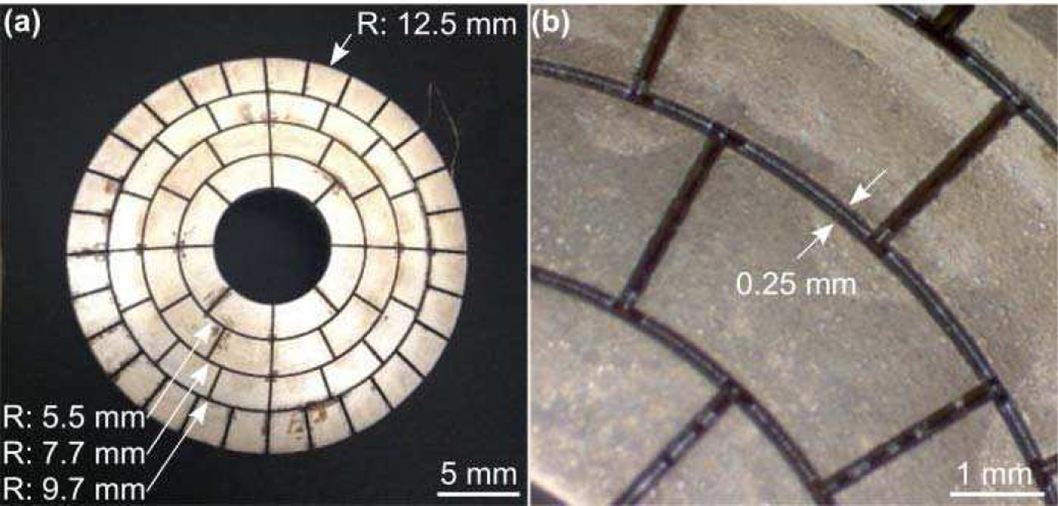
(a) Laser micromachined PZT transducer array. The outer radius (R) of each ring of elements is indicated (arrows). (b) Optical microscopy images of the diced PZT bowl. The kerf width is indicated (arrows).
Fig. 2 provides a schematic diagram of the transducer array fabrication workflow. Following micromachining, electrical connections were made to the individual array elements by soldering a micro coaxial cable to each of the inner air-backed electrodes. The array’s outer front electrode was soldered to a common ground via four micro coaxial cables. The micro coaxial cable bundle was attached to a custom multi-channel driving system using a DL series connector (ITT Cannon, Santa Ana, CA, USA). The phased array was housed within a 3D printed polyvinyl chloride (PVC) casing and sealed with epoxy (EPOTEK 301; Epoxy Technology, Billerica, MA, USA). The transducer aperture and housing were sealed with a thin layer (thickness = 10 µm) of Parylene (Specialty Coating Systems, Indianapolis, IN, USA). Following construction, the electrical impedance of each individual array element was matched to the driving system’s output impedance of 86 Ω and zero phase, to ensure maximal power transfer to the transducer.
Fig. 2.

Fabrication workflow of the high-frequency FUS phased array.
B. Free-Field Acoustic Characterization
Acoustic characterization of the phased array was performed in a rubber-lined, degassed/deionized water-filled tank (24 cm x 30 cm x 50 cm) using a calibrated planar fiber-optic hydrophone (FOH) [Fig. 3]. The FOH (active tip diameter = 10 µm; Precision Acoustics, Dorchester, Dorset, UK) was mounted on a three-axis positioning system (Parker Hannifin, PA, USA) with its active surface oriented perpendicular to the array’s acoustic axis (i.e., Z-axis). The phased array was driven at 3.3 MHz using the multi-channel driving system (pulse length = 20 µs, PRF = 100 Hz). Hydrophone recordings were captured by a digital oscilloscope (TDS 3014C; Tektronix, Richardson, TX, USA) and transferred to a CPU via General Purpose Interface Bus (GPIB) using software written in LAB-VIEW (National Instruments, Austin, TX, USA).
Fig. 3.
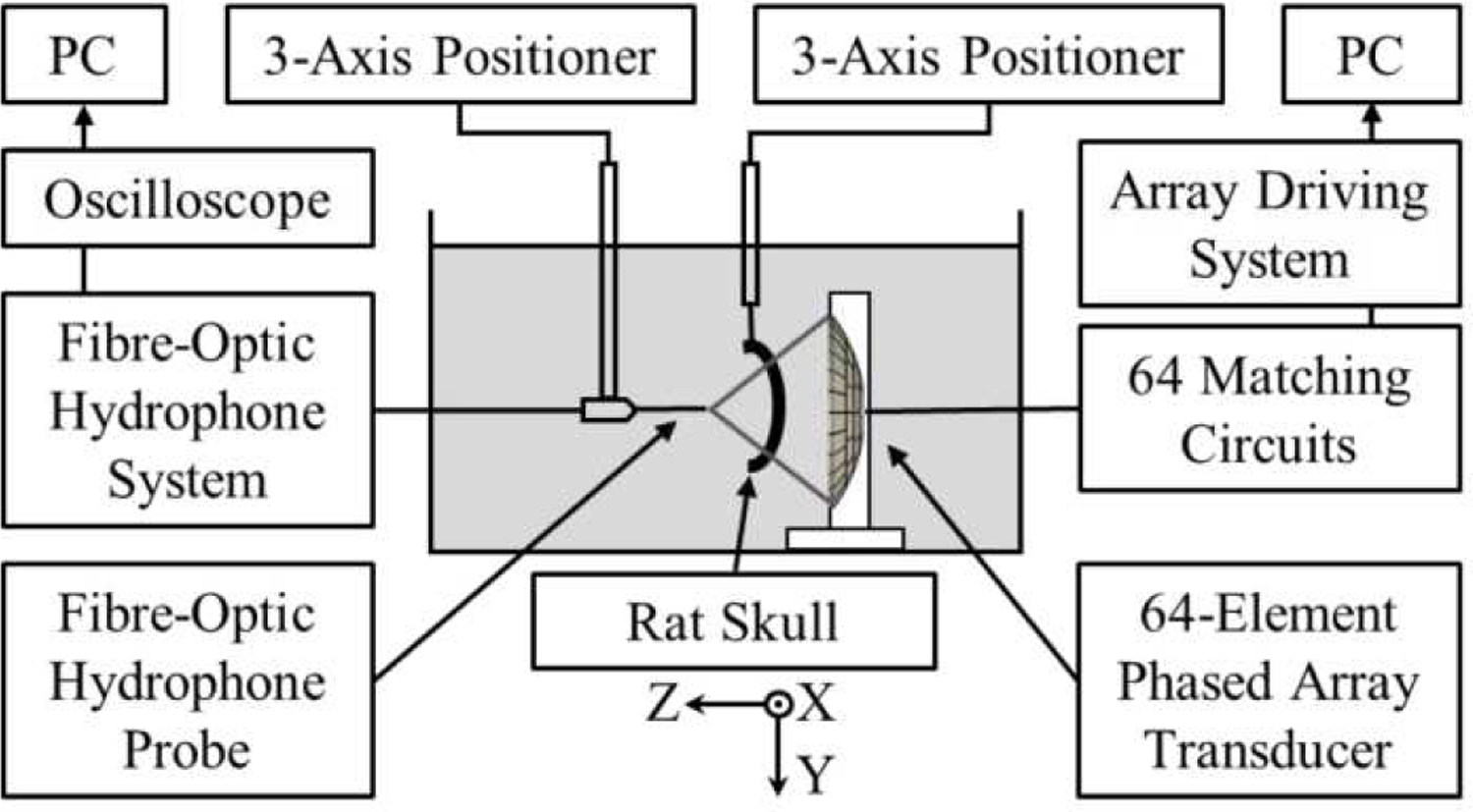
Experimental setup for acoustic characterization and trans-rodent skull focusing measurements.
Two dimensional (2D) acoustic field measurements were carried out in water at a total of 11 target locations spanning [−4.4, +4.4] mm along the X-axis and [−6.0, +6.0] mm along the Z-axis [Fig. 3]. The array elements were driven independently in sequence (pulse length = 20 µs) and the response of the FOH was recorded at each location of interest to determine the set of element-wise phases needed to focus the array to each target. The phased array was then steered electronically to each target location and the temporal-peak negative acoustic field distributions were recorded (number of averages = 32) at a fixed driving system input voltage in both the lateral (i.e., XY) and axial (i.e., XZ) planes (lateral scans: field-of-view = 4.4 λ× 4.4 λ; axial scans: field-of-view = 4.4 λ× 6.6 λ; pixel size = 0.22 λ× 0.22 λ; λ = 0.45 mm is the acoustic wavelength in water). The spatial-peak temporal-peak (SPTP) negative pressure as a function of the driving system input voltage was measured at the array’s geometric focus. The experimental measurements were compared with corresponding numerical simulations carried out in a homogeneous medium (sound speed = 1500 m/s) using a ray-acoustics propagation model [49]. In addition, large field-of-view simulations (lateral/axial scans: field-of-view = 44 λ× 44 λ) were carried out to investigate potential grating lobe formation during electronic beam steering. The array’s effective beam steering range (distance over which the SPTP negative focal pressure is greater than or equal to 50% of the value obtained when targeting the geometric focus and without introducing grating lobes) was estimated in both the lateral and axial directions via one-dimensional (1D) Gaussian fitting.
C. Trans-Rodent Skull Acoustic Characterization
The phased array’s trans-rodent skull focusing capabilities were investigated using four ex-vivo skullcap specimens (ID1-ID4). The skull samples were obtained from animal studies (male Sprague Dawley rats, 320–480 g) conducted with prior approval from the Animal Care Committee at Sunnybrook Research Institute, and that were in accordance with guidelines established by the Canadian Council on Animal Care and the Animals for Research Act of Ontario. The skullcaps were fixed in formaldehyde immediately following tissue harvest, following a protocol that has been shown to maintain the material properties of fresh skull specimens [50][51].
The experimental setup was similar to that described in section II.B. An ex-vivo rodent skullcap was mounted on a three-axis positioning system and inserted between the phased array transducer and the FOH probe. The skullcaps were positioned to emulate sonication of the mid-brain, with the outer skull surface oriented approximately perpendicular to the array’s acoustical axis and the array’s geometric focus located along the cranial midline at the depth of 5 mm from the inner skull surface. Skull specimens were degassed in a vacuum jar (Nalge, Rochester, NY, USA; Gast, Benton Harbor, MI, USA) at approximately −0.1 MPa for a minimum of 1 hr prior to experimentation.
For each skull specimen, trans-skull acoustic field measurements were conducted at the array’s geometric focus both with and without hydrophone-assisted phase aberration corrections [39]. To compute element-wise phase corrections, each array element was driven independently in sequence (pulse length = 20 µs, PRF = 100 Hz) and the response of the FOH was recorded at the transducer’s geometric focus both with and without an intervening rodent skullcap (number of averages = 64). The two sets of received signals (i.e., with and without skull specimen) were cross-correlated [52] to determine the phase delay induced by the rodent skull bone for each array element [39]. In determining the skull phase aberration corrections, cross-correlation was performed using data from the first 6 cycles of each pulse. Trans-skull temporal peak negative lateral (i.e., XY plane) acoustic field distributions (i.e., with and without phase aberration corrections) were compared with those obtained in the corresponding water-path case, and the SPTP negative pressure, peak sidelobe ratio, −6 dB focal area, and focal shift (i.e., in-plane distance from location of SPTP pressure to intended target) were computed as metrics of focal quality.
The impact of the transducer array orientation with respect to the rodent skullcap on the resulting transcranial focal quality was investigated using a single specimen (ID2). In practice, this corresponds to targeting different brain regions purely via mechanical repositioning of the phased array (i.e., without electronic beam steering). The skullcap was translated mechanically relative to both the phased array and FOH probe, both of which remained stationary. Trans-skull acoustic field measurements were conducted both with and without hydrophone-assisted phase corrections at a total of 5 transducer-skull orientations up to a distance of 5 mm lateral from the cranial midline.
III. Results
A. Free-Field Focusing and Beam Steering
1D acoustic field profiles generated when targeting the array’s geometric focus in free-field conditions are shown in Fig. 4. The focal beam full width at half maximum (FWHM) measured 0.4 mm and 2.6 mm in the lateral and axial directions, respectively [Fig. 4 (a–c)], corresponding to an ellipsoidal focal volume of ∼200 µm3 (defined by 50% pressure drop-off). The SPTP negative focal pressure was linearly correlated with the driving system input voltage, with the array generating free-field focal pressures of up to ∼6.5 MPa at an input of 25 V peak-to-peak [Fig. 4(d)].
Fig. 4.
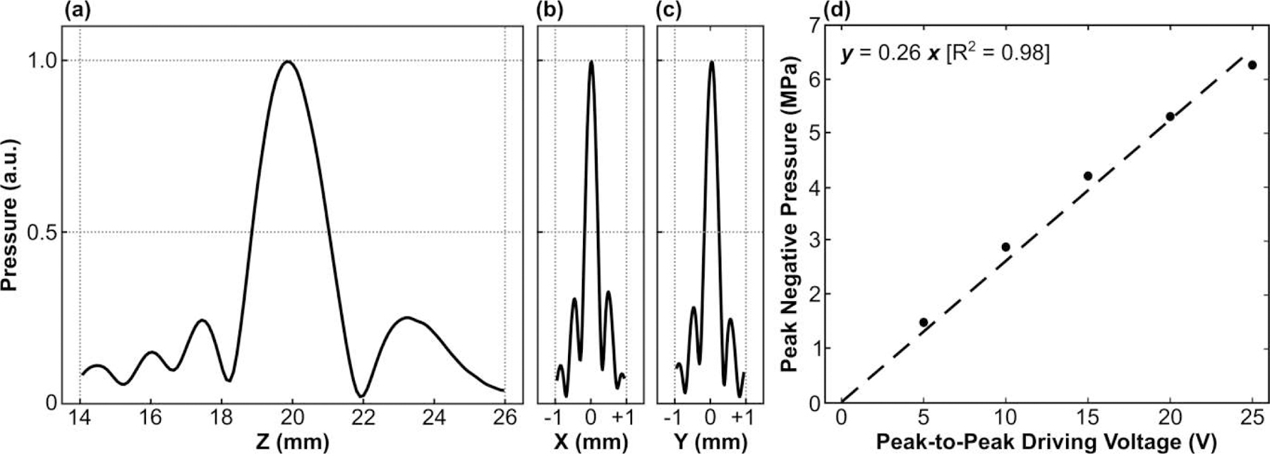
(a) Axial and (b,c) lateral 1D peak negative pressure profiles generated at the array’s geometric focus in free-field conditions. All plots are normalized to the SPTP negative pressure value. (d) SPTP negative pressure measured in free-field conditions as a function of the input peak-to-peak driving voltage. Linear regression was added to the plot (dashed line).
2D acoustic field distributions obtained when steering the array electronically to different target locations are provided in Fig. 5. The array was able to steer the beam electronically in both the lateral [Fig. 5(a)] and axial [Fig. 5(b)] directions, though the resulting focal quality varied depending on the target location. Although grating lobes were not apparent in the experimental measurements, large field-of-view numerical simulations revealed strong grating lobes when the array was steered a sufficient distance from the geometric focus [Fig. 6(a)]. At the most extreme targets investigated, the grating lobe amplitude far exceeded the pressure obtained at the intended focus [Fig. 6(b)].
Fig. 5.
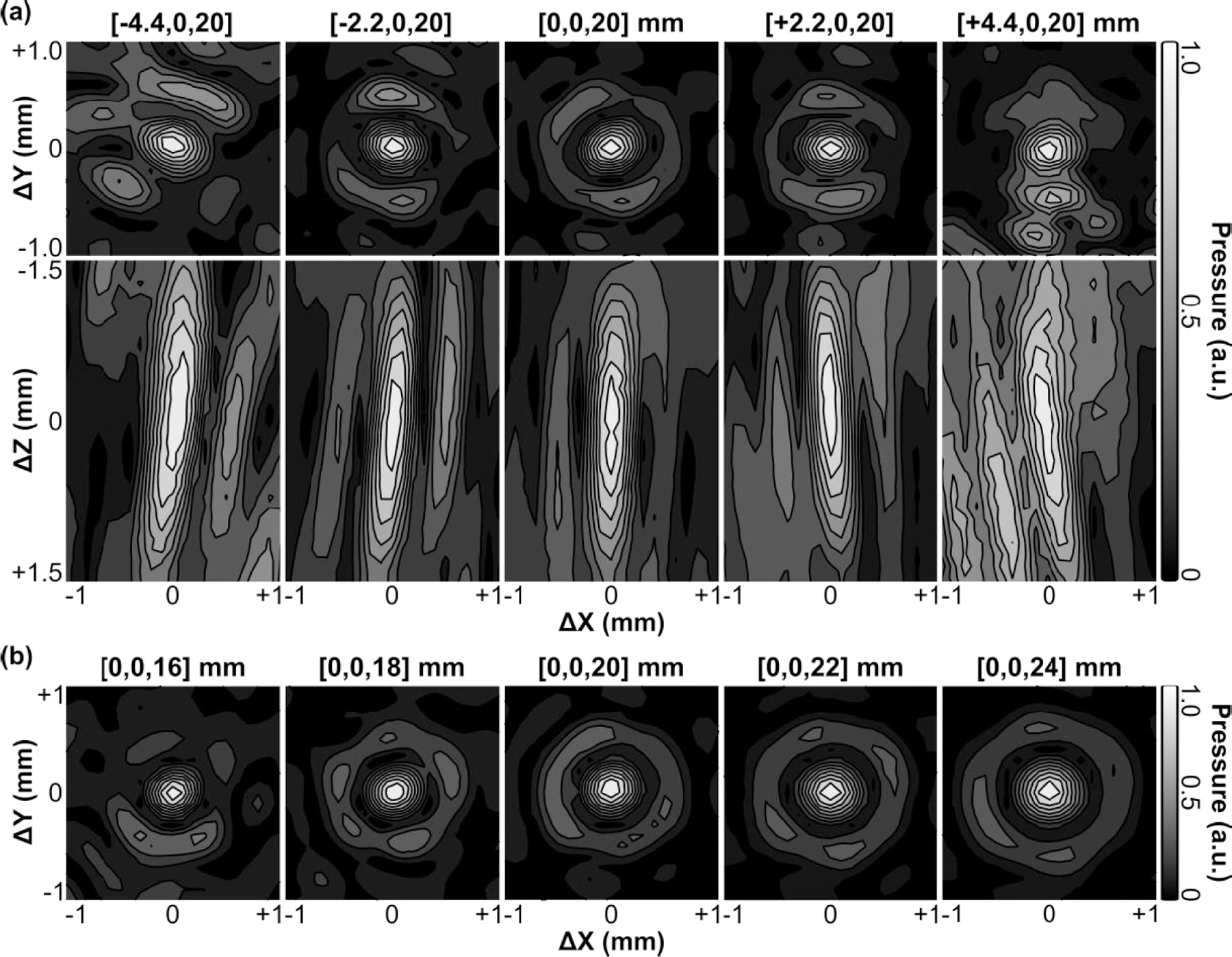
Contour images of the 2D lateral (XY-plane) and axial (XZ-plane) acoustic field distributions generated when steering the beam along the (a) lateral and (b) axial directions in free-field conditions. All plots are normalized to their respective SPTP negative pressure values. Axis labels are given relative to the listed target location. Linear contours are displayed at 10% intervals.
Fig. 6.
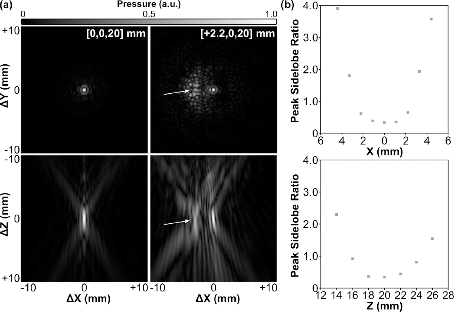
Large field-of-view acoustic field simulations. (a) 2D lateral (XY-plane) and axial (XZ-plane) acoustic field distributions generated at the array’s geometric focus and when steering 2.2 mm laterally. Grating lobes (arrows) are formed as the array is steered away from the geometric focus. All plots are normalized to their respective SPTP negative pressure values. Axis labels are given relative to the listed target location. (b) Peak sidelobe ratio as a function of target location along both the lateral (X-axis) and axial (Z-axis) directions.
The SPTP negative pressure and −6 dB lateral focal area as a function of steering distance along both the lateral and axial directions are quantified in Fig. 7. Focal pressure decreased symmetrically as the target location was steered laterally away from the array’s geometric focus (i.e., along ±X direction), whereas in the axial direction the focal pressure decreased more rapidly when steered distally to the transducer surface (i.e., +Z direction) than when steered proximally (i.e., -Z direction) [Fig. 7(a)]. Focal size increased as the target location was steered lateral and distal to the array’s geometric focus, and decreased when steered proximal to the transducer surface [Fig. 7(b)]. The array’s effective electronic beam steering range was estimated to be 4.5 mm and 6 mm in the lateral and axial directions, respectively. The results obtained from numerical simulations were in good agreement with the experimental measurements [Fig. 7].
Fig. 7.
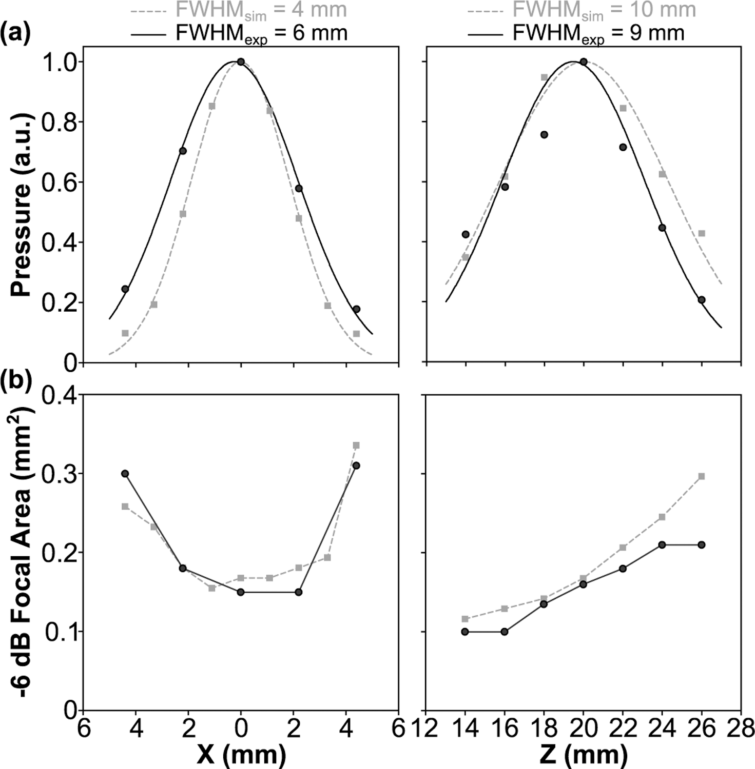
(a) Peak negative focal pressure and (b) −6 dB focal area obtained in free-field conditions as a function of target location along both the lateral (X-axis) and axial (Z-axis) directions. Data are provided from experimental measurements (black circles) and corresponding numerical simulations (gray squares). (a) 1D Gaussian fits were added the plots.
B. Trans-Rodent Skull Focusing
Transcranial acoustic field distributions generated at the array’s geometric focus for each rodent skull specimen are displayed in Fig. 8, along with corresponding water-path control data. The introduction of a rodent skullcap between the transducer array and target location severely distorted the shape and location of the focal region compared to the water-path control case(s) [Fig. 8]. However, by incorporating hydrophone-assisted phase corrections into the element driving signals, these skull-induced distortions were mitigated and the water-path focal quality was restored partially. The array’s trans-rodent skull focusing capabilities are quantified in Fig. 9. Across all skullcap specimens investigated, the transcranial SPTP negative pressure was reduced to 24% ± 4% of the corresponding water-path value without aberration correction, which improved to 31% ± 3% using phase corrections [Fig. 9(a)]. The peak sidelobe ratio was increased from 0.39 ± 0.03 in water to 0.65 ± 0.11 with an intervening rodent skullcap but without aberration correction, which improved to 0.42 ± 0.06 using phase corrections [Fig. 9(b)]. Similar trends were also obtained for both the −6 dB focal area [Fig. 9(c)] and focal shift [Fig. 9(d)]. The impact of the transducer array orientation with respect to the rodent skullcap on transcranial focal quality is illustrated in Fig. 10. Transcranial focusing via phase aberration corrections was feasible via mechanical repositioning of the transducer up to 5 mm lateral from the cranial midline, though the improvement in focal quality relative to the case without aberration corrections was dependent on the target location.
Fig. 8.
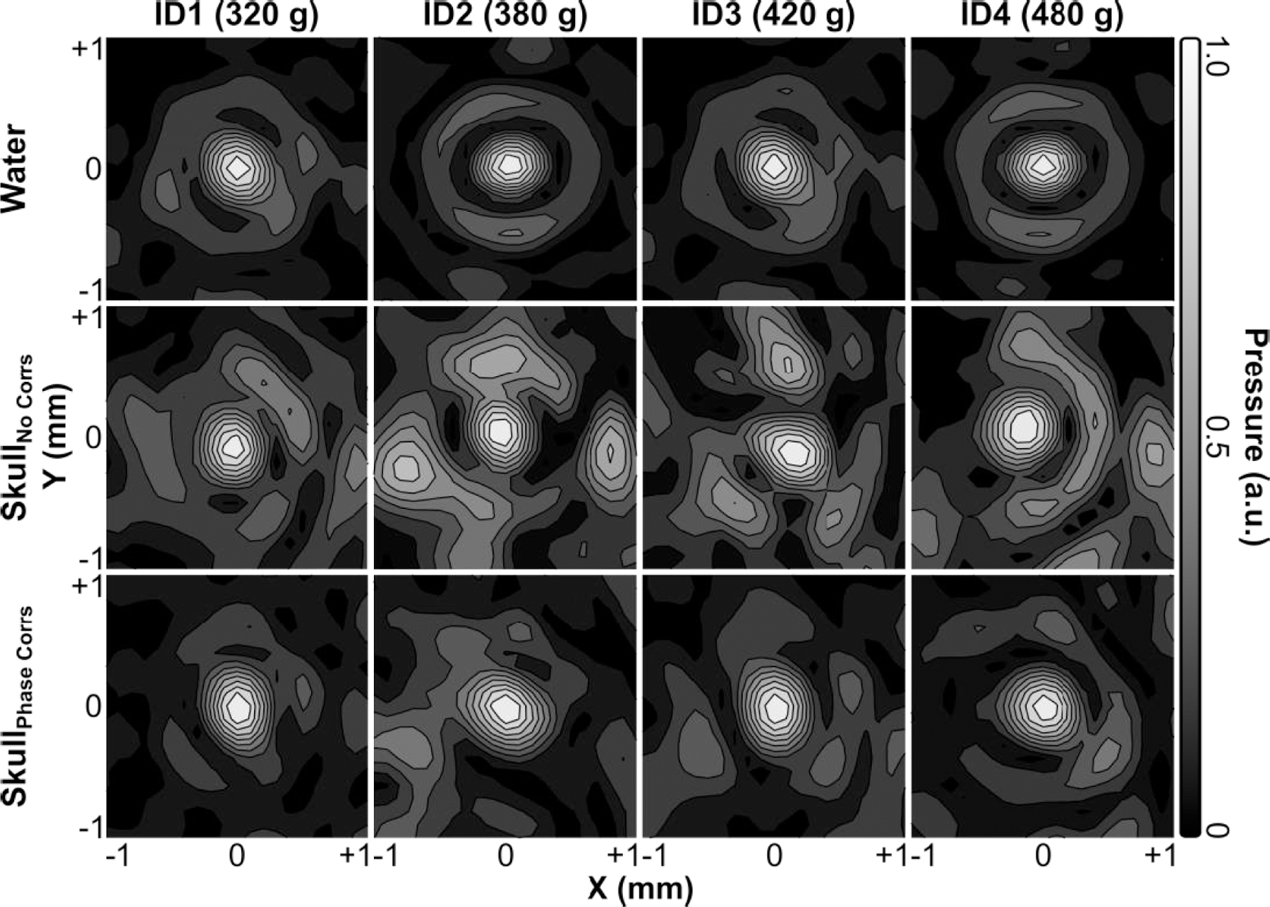
Contour images of the 2D lateral (XY-plane) acoustic field distributions generated at the array’s geometric focus when transmitting through an ex-vivo rodent skullcap (ID1-ID4, animal weights listed) both with and without hydrophone-assisted phase corrections, along with corresponding water-path control data. All plots are normalized to their respective SPTP negative pressure values. Linear contours are displayed at 10% intervals.
Fig. 9.
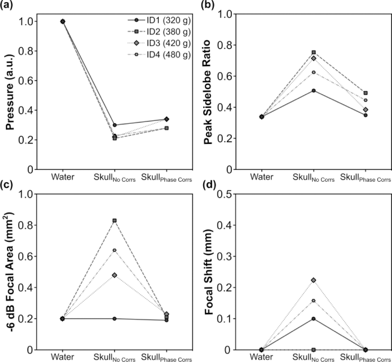
. (a) SPTP negative pressure, (b) peak sidelobe ratio, (c) −6 dB focal area, and (d) focal shift obtained when transmitting through an ex-vivo rodent skullcap (ID1-ID4, animal weights listed) both with and without hydrophone-assisted phase corrections, along with corresponding water-path control data.
Fig. 10.
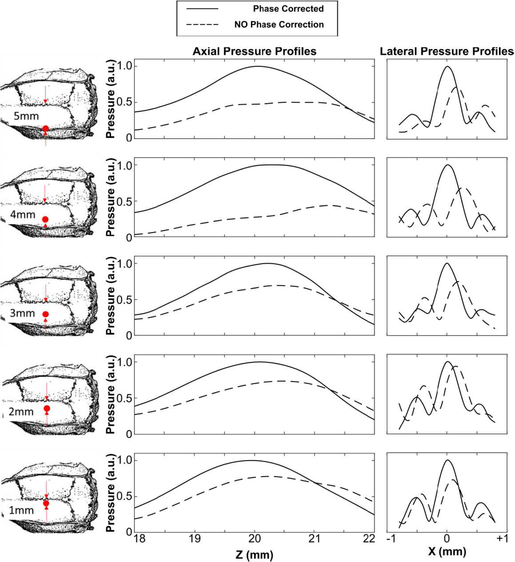
Axial and lateral 1D peak negative pressure profiles generated the array’s geometric focus when transmitting through an ex-vivo rodent skullcap (ID2) for five different transducer-skull orientations up to 5 mm lateral from the cranial midline. Data are provided both with and without hydrophone-assisted phase corrections. All plots are normalized to the SPTP negative pressure value of the phase correction case.
IV. Discussion
In this study, we present the design, fabrication, and characterization of a high-frequency phased array system for transcranial FUS delivery in small animals. The feasibility of using laser-micromachining techniques for phased array fabrication was demonstrated. Acoustic characterization measurements revealed the device was capable of generating highly localized focal volumes (0.4 mm x 0.4 mm x 2.6 mm) when transmitting through ex-vivo rodent skullcaps at a driving frequency of 3.3 MHz, provided phase aberration corrections were incorporated into the array element driving signals. The phased array’s steering capabilities were shown to be sufficient for targeting regions throughout the rodent skull cavity, and the achievable focal pressures appeared adequate for future in-vivo testing of transcranial FUS brain therapy. As the ultrasound frequency is increased and the wavelength approaches the thickness of the bone, the effects of skull-induced wave distortion on the resulting pressure field distribution become more pronounced [30]. Assuming a sound speed of approximately 2900 m/s in bone [50], the wavelength employed in this study (∼0.9 mm) was on the order of the rodent skullcap thicknesses (0.5–1.0 mm). We performed transcranial ultrasonic focusing using a phased array transducer and element-wise phase aberration corrections obtained from acoustic measurements performed with an implanted hydrophone [38][39], however, this invasive approach is impractical for in-vivo experimentation. Nevertheless, it may be possible to compute trans-rodent skull aberration corrections non-invasively via numerical simulations [53][54] based on micro-CT scans of the rat head [55], similar to the method employed during clinical FUS brain treatments [56][19]. Furthermore, element-wise amplitude corrections [40] may provide improved trans-rodent skull focal quality in future studies.
Based on our transcranial ultrasound field measurements, the mean pressure transmission of rodent skullcaps at a frequency of 3.3 MHz was estimated to be 31% ± 3%. This value is consistent with previous studies conducted using similar animal weights but at lower megahertz frequencies (i.e., 56.7% ± 2.8% at 2.53 MHz [30], ∼50% ± 35% at 2 MHz [32]), as insertion loss in bone is known to increase with increasing frequency [50]. However, it is worth noting that this prior work was carried out using single-element transducers [30][32], whereas in this study a phased array was employed. As a result, the pressure transmission factor may have been underestimated in the present work, due to imperfect constructive interference of the individual array elements at the focal point.
The effective electronic steering range of the array was estimated to by approximately 4.5 mm and 6 mm in the lateral and axial directions, respectively. Although this steering range may not allow FUS treatment throughout the rodent skull cavity on its own, it was shown that brain-wide targeting may be facilitated by mechanical re-positioning of the array. Future arrays with higher element counts may help mitigate grating lobe formation and enable full electronic steering within the rodent skull cavity without having to mechanically reposition the device [57][58]. Smaller array elements would also provide improved transcranial phase corrections, further reducing the transmission losses induced by the skull bone. However, the number of individual elements needs to remain within a practical range to simplify the fabrication procedure and minimize the total system cost.
Future work will involve in-vivo testing of the high-frequency phased array transducer. Our acoustic calibration results suggest the array is capable of generating sufficient trans-rodent skull focal pressures for microbubble-mediated blood-brain barrier permeablization [1]. McDannold et al estimated the pressure threshold for generating increased BBB permeability to be characterized by a mechanical index ([MI] = SPTP negative pressure/frequency1/2) value of 0.46 [59]. For a driving frequency of 3.3 MHz, this MI threshold corresponds to a SPTP negative pressure of ∼0.8 MPa, which is ∼40% of the estimated maximum trans-skull focal pressure obtainable, using the mean transmission factor of 31% ± 3% to de-rate the free-field results (∼2.0 ± 0.2 MPa). At higher amplitude exposure levels, ultrasound-stimulated microbubbles can induce vascular damage and ischemic necrosis dominantly through mechanical mechanisms [60][61][62], which may also be feasible with this device.
Acknowledgment
The authors would like to thank Moe Kazem for his assistance with transducer fabrication. This work was supported by funding from the National Institute of Biomedical Imaging and Bioengineering of the National Institute of Health (RO1-EB003268), the Canadian Institutes of Health Research (FDN 154272) and the Ontario Research Fund program. Support from the Temerty Chair in Focused Ultrasound Research at Sunnybrook Health Sciences Centre is also acknowledged.
References
- [1].Hynynen KJF, McDannold N, Vykhodtseva N, “Noninvasive MR Imaging–guided Focal Opening of the Blood-Brain Barrier in Rabbits,” Radiology, vol. 220, no. 3, pp. 640–6, 2001. [DOI] [PubMed] [Google Scholar]
- [2].Hynynen K et al. , “Focal disruption of the blood–brain barrier due to 260-kHz ultrasound bursts: a method for molecular imaging and targeted drug delivery,” J. Neurosurg, vol. 105, no. 3, pp. 445–454, 2006. [DOI] [PubMed] [Google Scholar]
- [3].Scarcelli T, Jordão JF, O’reilly MA, Ellens N, Hynynen K, and Aubert I, “Stimulation of hippocampal neurogenesis by transcranial focused ultrasound and microbubbles in adult mice,” Brain Stimul, vol. 7, no. 2, pp. 304–307, 2014. [DOI] [PMC free article] [PubMed] [Google Scholar]
- [4].Mooney SJ, Shah K, Yeung S, Burgess A, Aubert I, and Hynynen K, “Focused ultrasound-induced neurogenesis requires an increase in blood-brain barrier permeability,” PLoS One, vol. 11, no. 7, pp. 1–11, 2016. [DOI] [PMC free article] [PubMed] [Google Scholar]
- [5].Jordão JF et al. , “Amyloid-β plaque reduction, endogenous antibody delivery and glial activation by brain-targeted, transcranial focused ultrasound,” Exp. Neurol, vol. 248, pp. 16–29, 2013. [DOI] [PMC free article] [PubMed] [Google Scholar]
- [6].Burgess A et al. , “Alzheimer Disease in a Mouse Model: MR Imaging–guided Focused Ultrasound Targeted to the Hippocampus Opens the Blood-Brain Barrier and Improves Pathologic Abnormalities and Behavior,” Radiology, vol. 273, no. 3, pp. 736–745, 2014. [DOI] [PMC free article] [PubMed] [Google Scholar]
- [7].Leinenga G and Götz J, “Scanning ultrasound removes amyloid-b and restores memory in an Alzheimer’s disease mouse model,” Sci. Transl. Med, vol. 7, no. 278, 2015. [DOI] [PubMed] [Google Scholar]
- [8].McMahon D, Mah E, and Hynynen K, “Angiogenic response of rat hippocampal vasculature to focused ultrasound-mediated increases in blood-brain barrier permeability,” Sci. Rep, vol. 8, no. 1, p. 12178, 2018. [DOI] [PMC free article] [PubMed] [Google Scholar]
- [9].Treat LH, McDannold N, Zhang Y, Vykhodtseva N, and Hynynen K, “Improved Anti-Tumor Effect of Liposomal Doxorubicin After Targeted Blood-Brain Barrier Disruption by MRI-Guided Focused Ultrasound in Rat Glioma,” Ultrasound Med. Biol, vol. 38, no. 10, pp. 1716–1725, 2012. [DOI] [PMC free article] [PubMed] [Google Scholar]
- [10].Liu H-L et al. , “Blood-Brain Barrier Disruption with Focused Ultrasound Enhances Delivery of Chemotherapeutic Drugs for Glioblastoma Treatment,” Radiology, vol. 255, no. 2, pp. 415–425, 2010. [DOI] [PubMed] [Google Scholar]
- [11].and Muna Aryal NM, Vykhodtseva Natalia, Yong-Zhi Zhang, Juyoung Park, “Multiple treatments with liposomal doxorubicin and ultrasoundinduced disruption of blood-tumor and blood-brain barriers improves outcomes in a rat glioma model,” J. Control. Release, vol. 169, no. 0, pp. 103–111, 2013. [DOI] [PMC free article] [PubMed] [Google Scholar]
- [12].Nisbet RM, Van Der Jeugd A, Leinenga G, Evans HT, Janowicz PW, and Götz J, “Combined effects of scanning ultrasound and a tau-specific single chain antibody in a tau transgenic mouse model,” Brain, vol. 140, no. 5, pp. 1220–1230, 2017. [DOI] [PMC free article] [PubMed] [Google Scholar]
- [13].O’Reilly MA, Jones RM, Barrett E, Schwab A, Head E, and Hynynen K, “Investigation of the safety of focused ultrasound-induced blood-brain barrier opening in a natural canine model of aging,” Theranostics, vol. 7, no. 14, pp. 3573–3584, 2017. [DOI] [PMC free article] [PubMed] [Google Scholar]
- [14].Samiotaki G, Acosta C, Wang S, and Konofagou EE, “Enhanced delivery and bioactivity of the neurturin neurotrophic factor through focused ultrasound - Mediated blood-brain barrier opening in vivo,” J. Cereb. Blood Flow Metab, vol. 35, no. 4, pp. 611–622, 2015. [DOI] [PMC free article] [PubMed] [Google Scholar]
- [15].Fan CH et al. , “Noninvasive, Targeted, and Non-Viral Ultrasound-Mediated GDNF-Plasmid Delivery for Treatment of Parkinson’s Disease,” Sci. Rep, vol. 6, no. December 2015, pp. 1–11, 2016. [DOI] [PMC free article] [PubMed] [Google Scholar]
- [16].and Mead R. J. P. Brian P., Kim Namho, Wilson Miller G, Hodges David, Mastorakos Panagiotis, Klibanov Alexander L., Mandell James W., Hirsh Jay, Soo Suk Jung, Hanes Justin, “Novel Focused Ultrasound Gene Therapy Approach Noninvasively Restores Dopaminergic Neuron Function in a Rat Parkinson’s Disease Model,” Nano Lett, vol. 17, no. 6, pp. 3533–3542, 2017. [DOI] [PMC free article] [PubMed] [Google Scholar]
- [17].Mainprize T et al. , “Blood-Brain Barrier Opening in Primary Brain Tumors with Non-invasive MR-Guided Focused Ultrasound: A Clinical Safety and Feasibility Study,” Sci. Rep, vol. 9, no. 1, pp. 1–7, 2019. [DOI] [PMC free article] [PubMed] [Google Scholar]
- [18].Park SH et al. , “Safety and feasibility of multiple blood-brain barrier disruptions for the treatment of glioblastoma in patients undergoing standard adjuvant chemotherapy,” J. Neurosurg, pp. 1–9, 2020. [DOI] [PubMed]
- [19].Lipsman N et al. , “Blood–brain barrier opening in Alzheimer’s disease using MR-guided focused ultrasound,” Nat. Commun, vol. 9, no. 1, pp. 1–8, 2018. [DOI] [PMC free article] [PubMed] [Google Scholar]
- [20].Rezai AR et al. , “Noninvasive hippocampal blood-brain barrier opening in Alzheimer’s disease with focused ultrasound,” Proc. Natl. Acad. Sci, vol. 117, no. 17, p. 202002571, 2020. [DOI] [PMC free article] [PubMed] [Google Scholar]
- [21].Abrahao A et al. , “First-in-human trial of blood–brain barrier opening in amyotrophic lateral sclerosis using MR-guided focused ultrasound,” Nat. Commun, vol. 10, pp. 1–9, 2019. [DOI] [PMC free article] [PubMed] [Google Scholar]
- [22].Ellens NPK and Partanen A, “Preclinical MRI-Guided Focused Ultrasound: A Review of Systems and Current Practices,” IEEE Trans. Ultrason. Ferroelectr. Freq. Control, vol. 64, no. 1, pp. 291–305, 2017. [DOI] [PubMed] [Google Scholar]
- [23].Ma Y et al. , “In vivo 3D digital atlas database of the adult C57BL/6J mouse brain by magnetic resonance microscopy,” Front. Neuroanat, vol. 2, no. APR, pp. 1–10, 2008. [DOI] [PMC free article] [PubMed] [Google Scholar]
- [24].Goerzen D, Fowler C, Devenyi GA, Germann J, and Madularu D, “An MRI-Derived Neuroanatomical Atlas of the Fischer 344 Rat Brain for Automated Anatomical Segmentation,” Sci. Rep, no. 613, pp. 0–27, 2019. [DOI] [PMC free article] [PubMed] [Google Scholar]
- [25].West MJ, Coleman PD, Flood DG, and Troncoso JC, “Differences in the pattern of hippocampal neuronal loss in normal ageing and Alzheimer’s disease,” Lancet, vol. 344, no. 8925, pp. 769–772, 1994. [DOI] [PubMed] [Google Scholar]
- [26].Fearnley LA JM1, “Ageing and Parkinson’s disease: substantia nigra regional selectivity,” Brain, vol. 114, pp. 2283–2301, 1991. [DOI] [PubMed] [Google Scholar]
- [27].Drabycz S et al. , “An analysis of image texture, tumor location, and MGMT promoter methylation in glioblastoma using magnetic resonance imaging,” Neuroimage, vol. 49, no. 2, pp. 1398–1405, 2010. [DOI] [PubMed] [Google Scholar]
- [28].O’Neil HT, “Theory of Focusing Radiators,” J. Acoust. Soc. Am, vol. 21, no. 5, pp. 516–526, 1949. [Google Scholar]
- [29].Kossoff G, “Analysis of focusing action of spherically curved transducers,” Ultrasound Med. Biol, vol. 5, no. 4, pp. 359–365, 1979. [DOI] [PubMed] [Google Scholar]
- [30].O'Reilly MA, Muller A, and Hynynen K, “Ultrasound Insertion Loss of Rat Parietal Bone Appears to Be Proportional to Animal Mass at Submegahertz Frequencies,” Ultrasound Med. Biol, vol. 37, no. 11, pp. 1930–1937, 2011. [DOI] [PMC free article] [PubMed] [Google Scholar]
- [31].Dervishi E et al. , “Transcranial high intensity focused ultrasound therapy guided by 7 TESLA MRI in a rat brain tumour model: A feasibility study,” Int. J. Hyperth, vol. 29, no. 6, pp. 598–608, 2013. [DOI] [PubMed] [Google Scholar]
- [32].Gerstenmayer M, Fellah B, Magnin R, Selingue E, and Larrat B, “Acoustic Transmission Factor through the Rat Skull as a Function of Body Mass, Frequency and Position,” Ultrasound Med. Biol, vol. 44, no. 11, pp. 2336–2344, 2018. [DOI] [PubMed] [Google Scholar]
- [33].Treat LH, McDannold N, Vykhodtseva N, Zhang Y, Tam K, and Hynynen K, “Targeted delivery of doxorubicin to the rat brain at therapeutic levels using MRI-guided focused ultrasound,” Int. J. Cancer, vol. 121, no. 4, pp. 901–907, 2007. [DOI] [PubMed] [Google Scholar]
- [34].Marty B et al. , “Dynamic study of blood-brain barrier closure after its disruption using ultrasound: A quantitative analysis,” J. Cereb. Blood Flow Metab, vol. 32, no. 10, pp. 1948–1958, 2012. [DOI] [PMC free article] [PubMed] [Google Scholar]
- [35].Bing KF, Howles GP, Qi Y, Palmeri ML, and Nightingale KR, “Blood-Brain Barrier (BBB) Disruption Using a Diagnostic Ultrasound Scanner and Definity?? in Mice,” Ultrasound Med. Biol, vol. 35, no. 8, pp. 1298–1308, 2009. [DOI] [PMC free article] [PubMed] [Google Scholar]
- [36].Li GF et al. , “Improved Anatomical Specificity of Non-invasive Neuro-stimulation by High Frequency (5 MHz) Ultrasound,” Sci. Rep, vol. 6, no. December 2015, pp. 1–11, 2016. [DOI] [PMC free article] [PubMed] [Google Scholar]
- [37].Kyriakou A, Neufeld E, Werner B, Paulides MM, Szekely G, and Kuster N, “A review of numerical and experimental compensation techniques for skull-induced phase aberrations in transcranial focused ultrasound,” Int. J. Hyperth, vol. 30, no. 1, pp. 36–46, 2014. [DOI] [PubMed] [Google Scholar]
- [38].Thomas JL and Fink MA, “Ultrasonic beam focusing through tissue inhomogeneities with a time reversal mirror: application to transskull therapy,” IEEE Trans. Ultrason. Ferroelectr. Freq. Control, vol. 43, no. 6, pp. 1122–1129, 1996. [Google Scholar]
- [39].Hynynen K and Jolesz FA, “Demonstration of potential noninvasive ultrasound brain therapy through an intact skull,” Ultrasound in Medicine and Biology, vol. 24, no. 2 Ultrasound Med. Biol. 24, pp. 275–283, 1998. [DOI] [PubMed] [Google Scholar]
- [40].White J, Clement GT, and Hynynen K, “Transcranial Ultrasound Focus Reconstruction with Phase and Amplitude Correction,” IEEE Trans. Ultrason. Ferroelectr. Freq. Control, vol. 52, no. 9, pp. 1518–1522, 2005. [DOI] [PubMed] [Google Scholar]
- [41].Hynynen K and Jones RM, “Image-guided ultrasound phased arrays are a disruptive technology for non-invasive therapy,” Phys. Med. Biol, vol. 61, no. 17, pp. R206–R248, 2016. [DOI] [PMC free article] [PubMed] [Google Scholar]
- [42].Magnin R et al. , “Magnetic resonance-guided motorized transcranial ultrasound system for blood-brain barrier permeabilization along arbitrary trajectories in rodents,” J. Ther. Ultrasound, vol. 3, no. 1, p. 22, 2015. [DOI] [PMC free article] [PubMed] [Google Scholar]
- [43].Fite BZ et al. , “Magnetic resonance thermometry at 7T for real-time monitoring and correction of ultrasound induced mild hyperthermia,” PLoS One, vol. 7, no. 4, 2012. [DOI] [PMC free article] [PubMed] [Google Scholar]
- [44].Bing C et al. , “Localised hyperthermia in rodent models using an MRI-compatible high-intensity focused ultrasound system.,” Int. J. Hyperthermia, vol. 31, no. 8, pp. 813–22, 2015. [DOI] [PMC free article] [PubMed] [Google Scholar]
- [45].Haritonova A, Liu D, and Ebbini ES, “In Vivo application and localization of transcranial focused ultrasound using dual-mode ultrasound arrays,” IEEE Trans. Ultrason. Ferroelectr. Freq. Control, vol. 62, no. 12, pp. 2031–2042, 2015. [DOI] [PMC free article] [PubMed] [Google Scholar]
- [46].Hoogenboom M et al. , “Development of a high-field MR-guided HIFU setup for thermal and mechanical ablation methods in small animals,” J. Ther. Ultrasound, vol. 3, no. 1, pp. 1–11, 2015. [DOI] [PMC free article] [PubMed] [Google Scholar]
- [47].Jones RM and Hynynen KR, “Advances in acoustic monitoring and control of focused ultrasound-mediated increases in blood-brain barrier permeability,” Br. J. Radiol, vol. 92, no. 1096, pp. 1–13, 2019. [DOI] [PMC free article] [PubMed] [Google Scholar]
- [48].Mirza MS, Liu Q, Yasin T, Qi X, Li JF, and Ikram M, “Dice-and-fill processing and characterization of microscale and high-aspect-ratio (K, Na)NbO3-based 1–3 lead-free piezoelectric composites,” Ceram. Int, vol. 42, no. 9, pp. 10745–10750, 2016. [Google Scholar]
- [49].Fan X and Hynynen K, “The Effect Of Wave Reflection And Refraction At Soft Tissue Interfaces During Ultrasound Hyperthermia Treatments,” J. Acoust. Soc. Am, vol. 91, no. 3, pp. 1727–1736, 1992. [DOI] [PubMed] [Google Scholar]
- [50].Fry FJ and Barger JE, “Acoustical properties of the human skull,” J. Acoust. Soc. Am, vol. 63, no. 5, pp. 1576–1590, 1978. [DOI] [PubMed] [Google Scholar]
- [51].White PJ, Palchaudhuri S, Hynynen K, and Clement GT, “The effects of desiccation on skull bone sound speed in porcine models,” IEEE Trans. Ultrason. Ferroelectr. Freq. Control, vol. 54, no. 8, pp. 1708–1710, 2007. [DOI] [PubMed] [Google Scholar]
- [52].Knapp CH and Carter GC, “The Generalized Correlation Method for Estimation of Time Delay,” IEEE Trans. Acoust, vol. 24, no. 4, pp. 320–327, 1976. [Google Scholar]
- [53].Clement GT and Hynynen K, “A non-invasive method for focusing ultrasound through the human skull,” vol. 47, pp. 1219–1236, 2002. [DOI] [PubMed] [Google Scholar]
- [54].Aubry J-F, Tanter M, Pernot M, Thomas J-L, and Fink M, “Experimental demonstration of noninvasive transskull adaptive focusing based on prior computed tomography scans,” J. Acoust. Soc. Am, vol. 113, no. 1, pp. 84–93, 2003. [DOI] [PubMed] [Google Scholar]
- [55].Engelhorn T et al. , “In vivo micro-CT imaging of rat brain glioma: A comparison with 3 T MRI and histology,” Neurosci. Lett, vol. 458, no. 1, pp. 28–31, 2009. [DOI] [PubMed] [Google Scholar]
- [56].McDannold N, Clement G, Black P, Jolesz F, and Hynynen K, “Transcranial MRI-guided focused ultrasound surgery of brain tumors: Initial findings in three patients,” Neurosurgery, vol. 66, no. 2, pp. 323–332, 2010. [DOI] [PMC free article] [PubMed] [Google Scholar]
- [57].Sun J and Hynynen K, “Focusing of therapeutic ultrasound through a human skull: A numerical study,” J. Acoust. Soc. Am, vol. 104, no. 3, p. 1705, 1998. [DOI] [PubMed] [Google Scholar]
- [58].Sun J and Hynynen K, “The potential of transskull ultrasound therapy and surgery using the maximum available skull surface area.,” J. Acoust. Soc. Am, vol. 105, no. 4, pp. 2519–2527, 1999. [DOI] [PubMed] [Google Scholar]
- [59].McDannold N, Vykhodtseva N, and Hynynen K, “Blood-Brain Barrier Disruption Induced by Focused Ultrasound and Circulating Preformed Microbubbles Appears to Be Characterized by the Mechanical Index,” Ultrasound Med. Biol, vol. 34, no. 5, pp. 834–840, 2008. [DOI] [PMC free article] [PubMed] [Google Scholar]
- [60].McDannold NJ, Vykhodtseva NI, and Hynynen K, “Microbubble contrast agent with focused ultrasound to create brain lesions at low power levels: MR imaging and histologic study in rabbits,” Radiology, vol. 241, no. 1, pp. 95–106, 2006. [DOI] [PubMed] [Google Scholar]
- [61].Vykhodtseva N, McDannold N, and Hynynen K, “Induction of apoptosis in vivo in the rabbit brain with focused ultrasound and Optison®,” Ultrasound Med. Biol, vol. 32, no. 12, pp. 1923–1929, 2006. [DOI] [PubMed] [Google Scholar]
- [62].Huang Y, Vykhodtseva NI, and Hynynen K, “Creating brain lesions with low-intensity focused ultrasound with microbubbles: A rat study at half a megahertz,” Ultrasound Med. Biol, vol. 39, no. 8, pp. 1420–1428, 2013. [DOI] [PMC free article] [PubMed] [Google Scholar]


