Abstract
Objective
To evaluate the practical effectiveness of smart metal artifact reduction (SMAR) in reducing artifacts caused by metallic implants.
Methods
Patients with metal implants underwent computed tomography (CT) examinations on high definition CT scanner, and the data were reconstructed with adaptive statistical iterative reconstruction (ASiR) with value weighted to 40% and smart metal artifact reduction (SMAR) technology. The comparison was assessed by both subjective and objective assessment between the two groups of images. In terms of subjective assessment, three radiologists evaluated image quality and assigned a score for visualization of anatomic structures in the critical areas of interest. Objectively, the absolute CT value of the difference (ΔCT) and artifacts index (AI) were adopted in this study for the quantitative assessment of metal artifacts.
Results
In subjective image quality assessment, three radiologists scored SMAR images higher than 40% ASiR images (P<0.01) and the result suggested that visualization of critical anatomic structures around the region of the metal object was significantly improved by using SMAR compared with 40% ASiR. The ΔCT and AI for quantitative assessment of metal artifacts showed that SMAR appeared to be superior for reducing metal artifacts (P<0.05) and indicated that this technical approach was more effective in improving the quality of CT images.
Conclusion
A variety of hardware (dental filling, embolization coil, instrumented spine, hip implant, knee implant) are processed with the SMAR algorithm to demonstrate good recovery of soft tissue around the metal. This artifact reduction allows for the clearer visualization of structures hidden underneath.
Keywords: Smart metal artifact reduction (SMAR), Metallic implant, computed tomography
1. Introduction
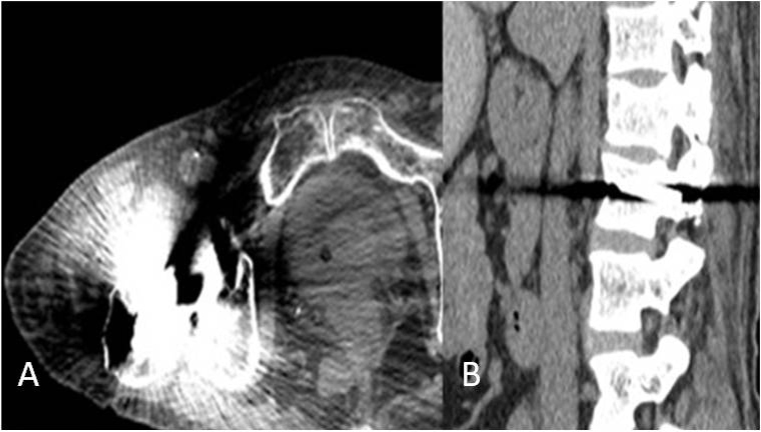
Computed tomography (CT) examinations are widely used in clinical diagnosis and post-operative evaluation. The artifacts induced by the metal implants could severely degrade image quality and thus impact diagnostic accuracy. Specifically, the presence of high density objects, such as dental fillings, orthopedic implants or other metal implant scan cause significant artifacts in the images due to beam hardening and photon starvation [1] (Fig. 1). Thus, reducing metal artifacts to improve image quality has become a hot research topic. Monochromatic images synthesized from spectral imaging CT, metal artifact reduction algorithm, and iterative reconstruction are the three mostly applied approaches to reduce metal artifacts [2,3,4,5,6]. However, these techniques are highly dependent on the composition of the metal materials and may not be fully effective for implants with high attenuation coefficients such as dental fillings and hip implants. In this study, CT images were reconstructed using 40% ASiR and SMAR algorithms, and the image quality and the effectiveness of metal artifact reduction were compared.
Figure 1.
A) Artifacts from photon starvation. B) Beam hardening artifact in the presence of metal.
2. Materials and Methods
2.1. Clinical data
Twenty-one patients were included in this study over 2 years, 13 male, and 8 female. The mean age was 66.8 years (range 56-75 years). Among the patients, there were instrumented spine (n=8), hip prostheses (n=7), dental filling (n=2), embolization coils to treat cerebral aneurysm (n=2) and knee prostheses (n=2). All of the hip prostheses, dental fillings, embolization coils and knee prostheses were unilateral.
Informed consent
Informed consent has been obtained from all individuals included in this study
Ethical approval
The research related to human use has been complied with all the relevant national regulations, institutional policies and in accordance the tenets of the Helsinki Declaration, and has been approved by the authors’ institutional review board or equivalent committee.
2.2. Image acquisition and processing
High-definition 64-row detector CT (Discovery CT750HD, GE Healthcare) was used with HiRes scanning mode. The scanning protocol was as follows: Detector coverage of 40 mm, scanning field of view of 32 cm, thickness of 0.625 mm, pitch of 0.984:1, rotation time of 0.8 s, matrix 512 × 512, scanning was acquired using 120 kVp and 410 mAs. All data were reconstructed with 40% ASiR and SMAR respectively for comparison. The CT images were assessed with a commercial workstation (GE VolumeShare AW 4.6; GE Healthcare). The window width and level were fixed at 2000 and 500 Hounsfield units (HU) for observing bony structure, and a window width of 400 HU and a window level of 40 HU were used for soft tissue observation.
2.3. Image quality analysis and measurement
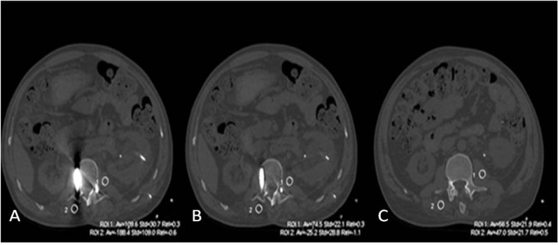
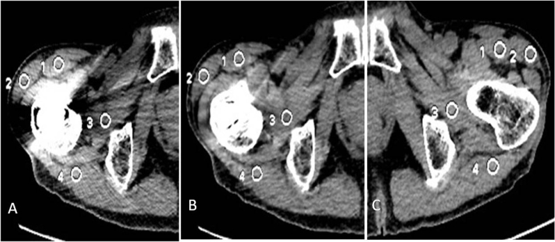
Subjective assessment: Three experienced radiologists (R1, R2, R3) with at least 10-year’s experience in general diagnostic radiology, blindly, and independently assessed the image quality using a 0-3 score scale [7]: Score 0 - image artifact was obvious, the bony structure and soft tissue near the artifact could not be observed and diagnosed. Score 1 -moderate artifacts in the image, the gross structure could still be observed, but affecting the diagnosis. Score 2 -mild artifacts and adjacent anatomic structures could be observed and diagnosed. Score 3 - no artifacts at all and definite diagnosis. The assessment included the severity of metal artifacts and the clarity of the adjacent structures. Objective image quality assessment: four circular regions of interest (ROI) were drawn near the metal implant in the slice where the artifacts were the most obvious and marked as ROI1art, ROI2art, ROI3art, ROI4art (Fig. 2, 3). Similar ROIs were placed at the corresponding part of the normal joint side (for joint implant) or at areas without artifacts (for instrumented spine and dental fillings) as the reference and were marked as ROI1ref, ROI2ref, ROI3ref, ROI4ref, (Fig. 2, 3). The location and size of ROIs for the same patient were consistent. The size of ROIs was 80~90 mm2. The CT value and standard deviation (SD) were measured in each ROI. The image quality was analyzed by comparing the CT value difference (ΔCT) and artifacts index (AI) between 40% ASiR images and SMAR images. The ΔCT and AI were calculated by the following formula [8]:
Figure 2.
Selection of the ROIs (white circles) near the metal implant for objective assessment of metal artifacts. ROIs in the CT images processed A) without B) with SMAR. C) Reference ROI was placed in the same soft tissue at no artifact level.
Figure 3.
A 65-year-old man with bilateral hip prosthesis. 4ROIs were dropped at the surrounding soft tissue on image A) without SMAR and B) with SMAR. C) Similar ROIs were dropped at the corresponding part of the normal side joint.
ΔCT = |CTart-CTref|, theoretically, the same soft tissue of a given patient should have approximately the same CT value. The ΔCT should reflect the influence of metal implant on the surrounding tissues [9]. AI=, higher AI value reflects higher degree of metal artifact.
2.4. Statistical analysis
SPSS 22.0 software (IBM, Chicago, Ill) was used for statistical analyses. For paired measurement data, we applied the t-test and the Wilcoxon signed-rank test. All experimental results are expressed by ±s. Differences were considered statistically significant at a p value < 0.05.
3. Results
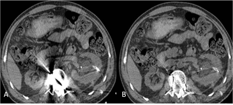
Considerable artifacts were produced by metal materials, showing both photon starvation and beam hardening effects (Fig. 4A, 5A), the artifacts were significantly decreased with the use of SMAR (Fig. 4B, 5B). During subjective image quality assessment, R1, R2 and R3 scored SMAR images higher than 40% ASiR images (R11.90 ± 0.30 vs 0.38 ± 0.49, P< 0.01; R2 2.00 ± 0.45 vs 0.29 ± 0.46, P < 0.01; R3 2.00 ± 0.45 vs 0.38 ± 0.49, P < 0.01). The results suggested that the SMAR approach was capable of reducing artifacts.
Figure 4.
Instrumented spine. A) The artifact subjective evaluation of the surrounding soft tissue is difficult without SMAR. B) the metal artifact is markedly reduced with SMAR and the surrounding structure can be evaluated.
Figure 5.
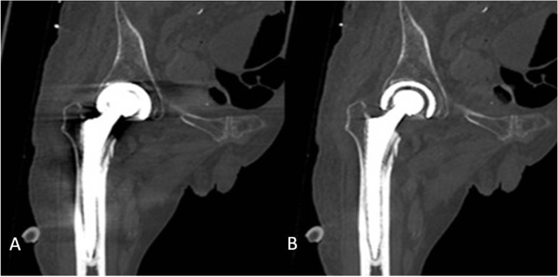
Unilateral right hip prosthesis on the same section. A) Without SMAR, the artifact from the hip prostheses is stronger, the edge of hip prosthesis and surrounding bony structure was unable to be observed clearly. B) With SMAR, the metal artifacts were decreased.
The objective analyses comparing 40% ASiR and SMAR are shown in Table 1. The ΔCT value of the 4 ROIs all appeared statistically significant (ROI1: 119.68 ± 25.27 vs 19.72 ± 5.3, t= 3.87, P < 0.05; ROI2: 71.57 ± 12.16 vs 19.96 ± 3.55, t= 4.07, P < 0.05; ROI3: 57.52 ± 6.98 vs 12.87 ± 3.03, t= 5.87, P < 0.05; ROI4: 71.51 ± 13.38 vs 19.83 ± 3.39, t= 3.74, P < 0.05). AI measured in the 4 ROIs between of the two groups of images similarly showed statistical significance (ROI1: 32.29 ± 3.91 vs 15.07 ± 2.07, t= 3.98, P < 0.05; ROI2: 28.12 ± 3.28 vs 14.26 ± 1.69, t= 3.75, P < 0.05; ROI3: 27.89 ± 4.72 vs 10.99 ± 1.03, t= 3.50, P < 0.05; ROI4: 23.61 ± 3.08 vs 9.67 ± 0.89, t= 4.35, P < 0.05). Thus, the SMAR appeared to be superior in reducing metal artifacts (Table 1), indicating that this technical approach was more effective in improving the quality of CT images.
Table 1.
Objective analyses comparing SMAR and 40% ASiR
| ΔCT | AI | |||||||
|---|---|---|---|---|---|---|---|---|
| ROI1 | ROI2 | ROI3 | ROI4 | ROI1 | ROI2 | ROI3 | ROI4 | |
| 40% ASiR | 119.68±25.27 | 71.57± | 57.52 | 71.51 | 32.29± | 28.12± | 27.89± | 23.61± |
| images | 12.16 | ±6.98 | ±13.38 | 3.91 | 3.28 | 4.72 | 3.08 | |
| SMAR images | 19.72±5.34 | 19.96± | 12.87± | 19.83± | 15.07± | 14.26± | 10.99± | 9.67± |
| 3.55 | 3.03 | 3.39 | 2.07 | 1.69 | 1.03 | 0.89 | ||
| t | 3.87 | 4.07 | 5.87 | 3.74 | 3.89 | 3.75 | 3.5 | 4.35 |
| P | <0.05 | <0.05 | <0.05 | <0.05 | <0.05 | <0.05 | <0.05 | <0.05 |
| ΔCT | AI | |||||||
| ROI1 | ROI2 | ROI3 | ROI4 | ROI1 | ROI2 | ROI3 | ROI4 | |
| 40% ASiR | 119.68±25.27 | 71.57± | 57.52 | 71.51 | 32.29± | 28.12± | 27.89± | 23.61± |
| images | 12.16 | ±6.98 | ±13.38 | 3.91 | 3.28 | 4.72 | 3.08 | |
| SMAR images | 19.72±5.34 | 19.96± | 12.87± | 19.83± | 15.07± | 14.26± | 10.99± | 9.67± |
| 3.55 | 3.03 | 3.39 | 2.07 | 1.69 | 1.03 | 0.89 | ||
| t | 3.87 | 4.07 | 5.87 | 3.74 | 3.89 | 3.75 | 3.5 | 4.35 |
| P | <0.05 | <0.05 | <0.05 | <0.05 | <0.05 | <0.05 | <0.05 | <0.05 |
4. Discussion
The primary objective of this prospective study was to investigate the effect of the SMAR approach in reducing artifacts of metallic implants. Metal artifact reduction in CT images presents a challenge and may impact the quantitative and diagnostic accuracy of the images. The presence of objects with high atomic number such as dental fillings, orthopedic implants, or other metal objects inside the body can cause significant artifacts, which could reduce the clarity of structure surrounding the metal and adversely affect the quality of the image. These artifacts can manifest in the form of streak/shading depending on the underlying physical phenomenon, which depends on the shape and composition of the metal. Major causes of metal artifacts can be generally classified as beam-hardening and photon starvation leading to data inconsistencies. A significant amount of X-ray can be scattered from the metal causing dark shading as well as dark/bright streaks which emanates from the metal object, and consequently obscuring structures of interest.
The spectrum of the X-rays penetrating the high-density object is significantly hardened and usually causes dark shading. The presence of metal causes evident photon starvation which results in very poor signal-tonoise ratio. These errors are further magnified during the reconstruction process, since the filtration step used in the reconstruction is effectively a derivative operator.
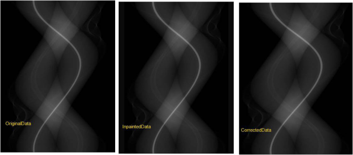
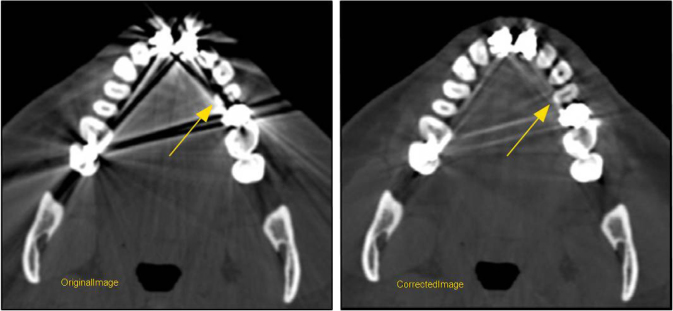
A combination of software and hardware techniques have been devised to tackle this issue: Different acquisition techniques can be used in object imaging such as using a higher kVp to reduce beam hardening artifacts. Scatter grids can be employed to reject scatter from the metallic object. Beam-hardening correction techniques can be utilized to specifically account for the type of the metal. However, these techniques are highly dependent on the composition of the metal and may not be fully effective for highly attenuating implants such as dental fillings and hip implants. Significant research has been performed in the broad area of projection inpainting. The idea of projection inpainting is to replace the projection data produced by the metallic object with a synthesized projection data using neighboring projection entries [7]or using a prior image [10,11,12]. This is a highly practical and effective approach for metal artifact reduction. However, there are three main challenges associated with the aforementioned approach: (1). Consistency of the synthetic projection data with the real projection data. (2). Effective replacement step to replace the real data with the synthetic projections to generate the inpainted projections. (3). Loss of resolution in the final reconstructed images. GESMAR methodology tackles all three challenges in an innovative manner. It is decomposed into three processing stages to address the above-mentioned challenges. In the first stage, the corrupted samples in the projection are identified. These samples correspond to the reading from the detectors that are impacted by the metallic object. Synthesized projections are generated using higher order interpolation and then back-projected to generate first stage of the MAR image. In the second stage, a prior image is generated using an innovative signal processing technique. Usually this type of image is usually generated from either the original image or the image after one step of the metal artifact reduction using multi-class segmentation methods [10,11,12]. However, these techniques have significant limitations especially due to the fact that the synthesized projections may not be consistent with the real data and as a result, the prior image may not be consistent with the real image. In order to overcome this limitation, GE utilizes a sophisticated signal processing technique to process the first stage MAR image before segmenting to generate the tissue classified prior image, which is then forward projected to generate the synthetic data and used to replace the corrupted projection samples. The third stage tackles the loss of resolution and low contrast detectability in the final reconstructed images. Improving this is important in obtaining acceptable clinical image quality. Previous approaches in improving image quality have been either in the image domain [13] or in the projection domain [14]. If designed correctly, the projection domain approach has an additional advantage of revealing anatomic details hidden behind the artifacts [14]. GE introduces an innovative approach in the projection domain in which the final corrected projection is generated using a combination of the original projection data and the inpainted projection (Fig. 6). The resulting projection has the desired characteristics of both the real data (better low contrast resolution) and inpainted projection (reduced artifacts). In addition, this technique is effective in revealing anatomic details that are hidden beneath the artifacts in the vicinity of the metal as shown in (Fig. 7).
Figure 6.
The corrected data is a combination of the original and inpainted data.
Figure 7.
The innovative approach in the projection domain reveals anatomic details obscured by the metallic artifacts and also preserves the low contrast resolution in the vicinity of the metal.
In this study, the subjective assessment of the three radiologists indicates that the image quality in all patients with metal implants was improved significantly by SMAR. All of the three radiologists scored SMAR images higher than 40% ASiR images. The suggests that the SMAR approach was capable of reducing artifacts. To better adequately evaluate the effect of artifact reduction between 40% ASiR images and SMAR images, we adopted two surrogate parameters (ΔCT, AI) for quantitative analysis. The ΔCT and AI of ROIs all appeared statistically significant. Thus, the SMAR appeared to be superior for reducing metal artifacts, indicating that this technical approach was more effective in improving the quality of CT images. In addition, previous studies on metal artifacts reduction focused on metal implants at a single anatomic site. In this study, clinical data sets with a variety of hardware (dental filling, coil, instrumented spine, hip implant, knee implant) from GE Discovery CT750 scanner platform were processed with SMAR algorithm to demonstrate the effectiveness of the proposed technique. We noted that the clinical data sets demonstrated good recovery of soft tissue and bony structure around the metal and artifact reduction allowing visualization of structures hidden underneath the artifacts, although Wang et al. [9] reported that the prior Metal Artifact Reduction System (MARS) did not always reveal the structure details in certain cases and presumably attributed to the calculated information of algorithm [15].
Our study has some limitations: Firstly, the number of patients was only 21, more participants are needed and will be recruited to further validate our clinical data for consistency. Secondly, we did not evaluate artifacts possibly attributable to SMAR on our images, although new artifacts elicited by CT reconstruction algorithms have been reported in existing literature [16, 17]. Finally, as SMAR is new, reference data is scarce, so we must confirm that the SMAR image reflects the true status of adjacent structures. Currently, efforts are underway to refine this preliminary study to address these issues.
5. Conclusions
The SMAR improves the quality of images and reduces artifacts to allow anatomic visualization of structures hidden underneath the artifacts by both subjective and objective measurement. This results in improved diagnostic confidence in patients with a variety of implants. However, the sample size within this study is small with only 21 patients recruited which limits the statistical power. Therefore, additional studies are required with a larger sample size.
Footnotes
Conflict of interest: Authors state no conflict of interest.
References
- [1].Barrett JF, Keat N.. Artifacts in CT: recognition and avoidance. Radiographics. 2004;24:1679–1691. doi: 10.1148/rg.246045065. [DOI] [PubMed] [Google Scholar]
- [2].Wang Y., Gao X, Lu A, Zhou Z, Baoxin L, Xizhao S.. et al. Residual aneurysm after metal coils treatment detected by spectral CT. Quant Imaging Med Surg. 2012;2:137–138. doi: 10.3978/j.issn.2223-4292.2012.06.04. [DOI] [PMC free article] [PubMed] [Google Scholar]
- [3].Roth TD, Maertz NA, Parr JA, Buckwalter KA, Choplin RH.. CT of the hip prosthesis: appearance of components, fixation, and complications. Radiographics. 2012;32:1089–1107. doi: 10.1148/rg.324115183. [DOI] [PubMed] [Google Scholar]
- [4].Lee MJ, Kim S, Lee SA, Song HT, Huh YM, Kim DH. et al. Overcoming artifacts from metallic orthopedic implants at high-field-strength MR imaging and multi-detector CT. Radiographics. 2007;27:791–803. doi: 10.1148/rg.273065087. [DOI] [PubMed] [Google Scholar]
- [5].Morsbach F, Bickelhaupt S, Wanner GA, Krauss A, Schmidt B, Alkadhi H.. Reduction of metal artifacts from hip prostheses on CT images of the pelvis: value of iterative reconstructions. Radiology. 2013;268:237–244. doi: 10.1148/radiol.13122089. [DOI] [PubMed] [Google Scholar]
- [6].Boas FE, Fleischmann D.. Evaluation of two iterative techniques for reducing metal artifacts in computed tomography. Radiology. 2011;259:894–902. doi: 10.1148/radiol.11101782. [DOI] [PubMed] [Google Scholar]
- [7].Zhou C, Zhao YE, Luo S, Shi H, Li L, Zheng L. et al. Monoenergetic imaging of dual-energy CT reduces artifacts from implanted metal orthopedic devices in patients with factures. Academic Radiology. 2011;18(10):1252–1257. doi: 10.1016/j.acra.2011.05.009. [DOI] [PubMed] [Google Scholar]
- [8].Li X, Feng W, Dong Ch. et al. The experimental quantitative study of spectral CT imaging in reducing the metal artifacts [J] Chinese Journal of Radiology. 2011;45(8):736–739. [Google Scholar]
- [9].Wang F, Xue H, Yang X.. Reduction of Metal Artifacts From Alloy Hip Prostheses in Computer Tomography. Journal of Computer Assisted Tomography. 2014;38(6):828–833. doi: 10.1097/RCT.0000000000000125. [DOI] [PubMed] [Google Scholar]
- [10].Bal M, Spies L.. Metal artifact reduction in CT using tissue-class modeling and adaptive prefiltering. Med. Phys. 2006;33:2852–9. doi: 10.1118/1.2218062. [DOI] [PubMed] [Google Scholar]
- [11].Prell D., Kyriakou Y, Beister M, Kalender WA.. A novel forward projection-based metal artifact reduction method for flat-detector computed tomography. Phys. Med. Biol. 2009;54:6575–91. doi: 10.1088/0031-9155/54/21/009. [DOI] [PubMed] [Google Scholar]
- [12].Meyer E, Raupach R, Lell M, Schmidt B, Kacheirless M.. Normalized metal artifact reduction in computed tomography Med. Phys. 2010;10:5482–93. doi: 10.1118/1.3484090. [DOI] [PubMed] [Google Scholar]
- [13].Koehler T., Brendel B, Brown K.. A new method for metal artifact reduction in CT. Second CT Meeting. 20122012:29–32. [Google Scholar]
- [14].Zhao S., Kyongtae B, Whiting B, Wang G.. A wavelet method for metal artifact reductionwith multiple metallic objects in the field of view. J. X-Ray Sci. Tech. 2002;2002;10:67–76. [Google Scholar]
- [15].Hilgers G, Nuver T, Minken A.. The CT number accuracy of a novel commercial metal artifact reduction algorithm for large orthopedic implants. J Appl Clin Med Phys. 2014;15:4597. doi: 10.1120/jacmp.v15i1.4597. [DOI] [PMC free article] [PubMed] [Google Scholar]
- [16].Cheng PM, Romero M, Duddalwar VA.. Pulmonary pseudoemboli: a new artifact arising from a commercial metal artifact reduction algorithm for computed tomographic image reconstruction. J Comput Assist Tomogr. 2014;38:159–62. doi: 10.1097/RCT.0b013e3182aac5de. [DOI] [PubMed] [Google Scholar]
- [17].Wang Y., Qian B, Li B, Qin G, Zhou Z, Qiu Y.. et al. Metal artifacts reduction using monochromatic images from spectral CT: evaluation of pedicle screws in patients with scoliosis. Eur J Radiol. 2013;82:e360–e366. doi: 10.1016/j.ejrad.2013.02.024. [DOI] [PubMed] [Google Scholar]


