Abstract
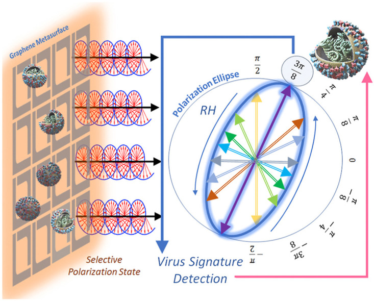
We propose a novel method to exploit chirality of highly sensitive graphene plasmonic metasurfaces to characterize complex refractive indexes (RI) of viruses by detecting the polarization state of the reflected electric fields in the THz spectrum. A dispersive graphene metasurface is designed to produce chiral surface currents to couple linearly polarized incident fields to circularly polarized reflected fields. The metasurface sensing sensitivity is the result of surface plasmon currents that flow in a chiral fashion with strong intensity due to the underlying geometrical resonance. Consequently, unique polarization states are observed in the far-field with the ellipticity values that change rapidly with the analyte’s RI. The determination of bimolecular RI is treated as an inverse problem in which the polarization states of the virus is compared with a pre-calculated calibration model that is obtained by full-wave electromagnetic simulations. We demonstrate the polarization selective sensing method by RI discrimination of three different types of Avian Influenza (AI) viruses including H1N1, H5N2, and H9N2 is possible. Since the proposed virus characterization method only requires determination of the polarization ellipses including its orientation at monochromatic frequency, the required instrumentation is simpler compared to traditional spectroscopic methods which need a broadband frequency scan.
Keywords: Biosensors, Graphene, Surface plasmon polariton, Terahertz, Virus sensing
Graphical abstract
1. Introduction
During the last few decades, respiratory diseases such as Severe Acute Respiratory Syndrome (SARS), Middle East Respiratory Syndrome (MERS), influenza A (FLUAV) caused severe health crisis in many countries. Recently, the spread of COVID-19 pandemic has caused major health emergency that led to worldwide social and financial catastrophe. Virus detection is often considered as the first stage of defence to stop the spread of disease and provide effective medical treatment to the infected patients. One of the reasons in the failure of health care systems and spark rise in infections during pandemic is the time-consuming detection of viruses at mass scale [1,2]. Real-time polymerase chain reaction (RT-PCR) is accepted as gold standard for detecting many respiratory viruses. But it involves labour-intensive post processing which often takes four to five days for compilation of the test results. Since the virus contagion and severity of infection increases with time, it is extremely important to curb the epidemic-related destruction by developing rapid, sensitive and reliable virus sensing techniques [[1], [2], [3], [4]].
Conventional optical spectroscopic methods for virus identification rely on the use of fluorescent materials such as dyes to label the target biomolecules [3,[5], [6], [7], [8]]. Lately, immunoassay based on localized surface plasmon resonances (LSPR) has been introduced to improve detection limit at nanoscale for both solution and substrate based metallic nanoparticles [2,9]. More recently, bioengineered ligands capped with plasmonic nanoparticles have been proposed for the detection of the SARS-CoV-2 virus [3,4]. A label-free microfluidic platform was developed to detect trace amount of antibodies against SARS-CoV-2 through LSPR induced on gold nanoparticles [2]. Reusable chip based on surface plasmon resonance sensor was developed to detect influenza viruses [10]. Bioengineered nanocomposite materials are successfully used for targeted drug delivery for cancer therapy [11,12]. Anti-adhesive strain sensors are designed to monitor bacterial droplets in complex environments [13]. The antibacterial and anti-adhesive fabric was synthesized by beetle like quaternary ammonium salts [14]. Nanohybrid materials based on metal oxide framework platform are designed to selectively determine presence of cancer cells [15]. Similarly, label free aptasensor are designed for sensitive detection of antibodies [16].
Since the binding energy of many protein-ligands offer vibrational modes in THz spectrum, the THz spectroscopy has been widely adopted for label-free biomolecule sensing. The traditional electromagnetic sensors are devised on the principle of field-matter interference. Small perturbation are introduced in the sensing environment that alters the orientation of the surrounding electromagnetic fields [17]. Recently, the laser cavity mode resonances are utilized for sensing applications at THz frequencies. The Fabry Perot resonances due to interference originating from multiple reflections between the metasurface and the ground plane can be compared to laser resonant cavity [[18], [19], [20], [21]]. As a result, ultrahigh Q-factor cavities with narrow absorption bandwidth can be achieved allowing for sensitive refractive index sensing applications.
Surface plasmon resonance (SPR) based immunoassays are widely adopted for such label-free biomaterial sensing and clinical diagnostics [[22], [23], [24]]. Plasmonic biomolecular sensor utilizes specific bio-receptor to intact viruses or viral proteins. Typically, such bioreceptors are made of antibodies that are found in animals that works to identify and defuse viral proteins or antigens. There are also range of other laboratory made artificial biomolecules that only binds to a specific target antigen. The surface plasmon resonance can continuously monitor binding kinetics for any potential biomolecular activity in real time by measuring local refractive change surrounding the metal. The reaction between biomolecules are enabled by bioreceptors (antibodies) immobilized on the top of metal surface, whereas the sample under test is injected into the same solution through flow cell [22,23]. The binding event occurs only with the presence of antigen resulting in change in local refractive index. For example, the commercially available SPR-based Biacore systems can accurately sense complex biomaterial samples [25]. However, the sensitivity of the SPR sensors is not suitable for virus testing because of the low absorption cross section of the virus that causes hard-to-detect minute optical variations. In addition, bulky components such as large prisms are required to introduce a reasonable coupling between the surface plasmons and light waves which leads to portability issues and inefficient utilization of such sensing systems [7,26].
To solve some of the issues associated with the surface plasmon sensors, low profile plasmonic metasurfaces were introduced in the field of biosensing [27,28]. The metasurfaces offer higher sensitivity because of the excitement of localized high intensity surface plasmons. Their interaction with the biomolecules induce detectable spectral changes with considerably reduced sensing footprint [[29], [30], [31], [32], [33], [34]]. Plasmonic metasurfaces are proposed for detection of low concentration of analyte [8,32,[35], [36], [37], [38], [39]]. Graphene have been extensively investigated for photovoltaics and energy storage applications [40,41]. Recently, LSPR in graphene metasurface sensors are proposed to efficiently sense the surrounding medium properties [42]. In particular, the graphene based LSPR biosensors offer low profile and portable prototypes to detect various types of virus strains [43,44]. Since the complex refractive index of biomolecules such as viruses are nearly comparable, it is often difficult to clearly distinguish between them from the spectral amplitude of scattered fields. Moreover, a wide spectrum has to be scanned in order to determine the amplitude resonant signature and the corresponding resonant frequency which increases the complexity of the detection set up [27,34,45].
In this paper, we propose a Chiral biosensor to differentiate respiratory viruses based on the polarization states of the reflected electromagnetic waves. A biosample can be fully characterized by detecting the discrete frequency polarization (or chiral) states without performing the wide spectral scan. The proposed detection scheme is built on our recent publications on circular dichroism in chiral metasurfaces [46,47]. Graphene metasurface are used for dynamic tunability of broadband THz waves [18,48]. These metasurfaces were composed of highly dispersive resonant unit cells that support chiral surface plasmon currents so that the energy of linearly polarized incident fields is coupled to cross-polarized fields. To match the THz vibrational modes, which are associated with most of the biomolecules and viruses [49], the designed Graphene metasurface is resonantly tuned between 1 and 2 THz. The graphene surface plasmon provides high near field enhancement at the substrate interface. The biomaterial analyte is deposited on the graphene cells as a thin superstrate layer and the metasurface is illuminated by a linearly polarized electromagnetic wave. The refractive index of the analyte is extracted from the reflection polarization state by comparing it with pre-calculated calibration curves obtained from full-wave numerical simulations. It is shown by numerical examples that the different types of viruses that have close resemblance of the refractive indexes can be differentiated by the variation in the polarization states of their respective reflected spectrum. In particular, three types of influenza viruses H1N1, H5N2, and H9N2 were shown to exhibit distinguished polarization states (and hence can be isolated). Since the shape of the polarization ellipse determines the type of the virus, the broadband spectral scan is not required in the polarization sensing method. The cost of the measurement equipment can be dramatically reduced since the analysis of the electric field at single frequency is sufficient to completely characterize the virus. Moreover, if employed with the traditional spectral scanning methods, the polarization sensing may also reduce the ambiguity by adding another degree of freedom to the measurement. We anticipate that the resonant polarization state sensing can be potentially exploited to determine the of other novel viruses such as SARS-CoV-2 whose optical properties have not been determined yet.
2. Sensing principle
The difference between the spectral sensitive biosensing and the proposed polarization sensitive detection is illustrated in Fig. 1 . The LSPR spectral scanning biosensing uses plasmonic nanoparticles that support high near fields surrounding the metal surface, as shown in Fig. 1 (a). Several plasmonic immunoassay sensing methods are proposed using such scheme utilizing the strong interaction between the target biomolecules and the strong LSPR on metallic nanoparticles both in aqueous solution or substrate form [2,4,45]. The reflected fields depends on the resonant absorption spectrum supported by the host materials including plasmonic nanoparticles and biomaterials. As LSPR are very sensitive to background refractive index therefore a small change can be detected in the form of shift () in spectral signature of the reflected field. The spectral shift is often attributed to the biomolecular binding event that increases the refractive index of the local medium. The spectral sensitive LSPR biosensing approach demonstrates efficient way to distinguish materials with closely related optical properties. However, it is clear that a broadband incident fields and spectral transform of scattered fields are necessary to recognize the spectral resonant response of the binding event.
Fig. 1.
(a) The traditional LSPR based sensing method based on nano-plasmonic resonator either in solution or substrate form. Spectral transform provides resonant frequency signature to distinguish between biomolecular binding or no binding event. (b) Proposed spectrum free (monochromatic) polarization state sensitive biosensing method where linearly x-polarized electric field impinges on dispersion engineered chiral LSPR metasurface. Three different reflected signals left ()/right () handed elliptical and linearly y-directional polarized () are provided as examples. (c) Reversible polarization states supported by metasurface i.e., left hand (LH) or right hand (RH) ellipses along with orientation angle (θ) due to variation in RI (, , ) of the target analyte. (d) Polarization ellipses for incident and reflected signals , and in -plane.
The polarization sensitive LSPR sensing method, depicted in Fig. 1(b), is based on chiral metasurfaces which are dispersion-engineered to support reversible reflected polarization states with electric field orientations that rapidly change with the refractive index of the host medium. This inherent chiral behavior is attributed to the helicoidal surface plasmon current distribution that flows in small closed loops on the surface of graphene metasurface. The sensing principle is illustrated in Fig. 1(b), where an x-polarized monochromatic plane wave is shown to impinge on the metasurface. The unique orientation angle of the reflected polarization state (ellipse) corresponds to the refractive index of the target analyte and the associated binding event. The ability of the metasurface to distinguish between two materials of closely-valued refractive indexes plays an important role in the discrimination of the optically-close biomolecular elements.
To demonstrate signature detection of biomolecules, three different scenarios are considered i.e. a biomolecule with no binding event, Type I binding and Type II binding. The three binding types are characterized by respective refractive indexes (RI) of , and of the target analyte medium in the order shown in Fig. 1(c). The higher sensor sensitivity follows from the distinctive resonant features of the constituent metasurface unit cells that lead to sharp variation in the phase difference between electric field vector components. Consequently, the resulting polarization states also show large variations from LH to RH with slight variation of RI between to , as depicted in Fig. 1(c). This abrupt change leads to a drastic inversion of the polarization state from clockwise to anti-clockwise rotation, as shown in Fig. 1(b)–(d). In addition, the orientation angle also sharply changes with the associated change in RI. Considering the unique polarization state characteristics, each binding event can be uniquely traced by (i) linearly polarized (), (ii) Left handed (LH) () and (iii) Right handed (RH) () elliptically polarized reflected fields.
3. Chiral graphene metasurface design
The polarization sensitivity of the plasmonic chiral metasurfaces [46,47] stems from two important design factors. Firstly, the unit cell geometrical shape should support chiral or helicoidal surface currents that produce elliptically polarized electric fields in the far-field reflectance spectrum. Secondly, the dimensions of the unit cells should be selected in such a way that a resonance is excited at the detection frequency. Taking these two factors into consideration, a unit cell with a split-ring configuration is adopted which consists of two L-shape graphene elements of slightly different dimensions, as depicted in Fig. 2 . The appropriate choice of substrate material determines the resonance frequency and absorption characteristics. The substrate backed by a perfect reflecting ground plane, is a Quartz material with a thickness of d = 15 μm. Quartz material offer low loss optical absorption and remains disperionless () in the range of frequencies between 1 and 2 THz [50]. The periodicity of unitcell is p = 10 μm. Graphene metasurfaces are typically fabricated by Chemical Vapor Deposition (CVD) process where specific patterns can be included by photolithography [51].
Fig. 2.
The Chiral biosensor is constructed by replicating a diagonally-symmetrical unit cell which consists of a graphene split ring designed with two L-shaped resonators. Different dimensions are given by = 7.5 μm and = 6 μm and width of split ring is 1 μm. The distance between two unit cells (periodicity) is p = 10 μm. The incident linearly polarized electric fields are reflected as elliptically polarized electromagnetic waves whose ellipticity depends on the dielectric characteristics of the analyte (sample under test).
The reflection characteristics can be deduced by corresponding components of reflected electric field vector. The incident ( , ) and reflected ( , ) fields are related by the reflection coefficient () in terms of the Jones matrix representation:
| (1) |
If x-directed incident field is assumed such as in Fig. 1 (d), the coefficients and can be ignored.
To demonstrate the principle of polarization conversion, a numerical model is created in the full-wave electromagnetic simulator COMSOL Multiphysics. The permittivity () of graphene is depending on the surface conductivity function ()
| (2) |
where, is the vacuum permittivity and nm is the monolayer thickness of graphene. The graphene surface is modelled by a material layer and the frequency dependent conductivity is obtained from the Kubo’s formula [[52], [53], [54], [55], [56]], i.e.,
| (3) |
Here, meV is the chemical potential of graphene, is the damping coefficient, m/s is the Fermi velocity, and is the electron mobility, is the electronic unit-charge, T is temperature, is the Boltzmann constant, and is the reduced Plank’s constant.
Assuming periodic boundary conditions, the metasurface is numerically illuminated by a linearly polarized incident plane wave and the resulting co- and cross-polarized reflection coefficients are depicted in Fig. 3 (a) and (b). Note the diagonal symmetry of the unit cell which makes the metasurface’s behavior independent of the incident polarization. Therefore, in Eq. (1) the two co- and cross-polarization reflection coefficients along x- and y-directions are identical i.e. and . Looking at Fig. 3 (a), it can be observed that multiple resonances are formed at 1.136, 1.513 and 1.92 THz at which the linear to cross-polarization conversion is almost perfect (i.e. ). This corresponds to effective unit cell size p being several times smaller than incident wavelength, i.e., . However, from the sensing viewpoint, more important are the spectral points at which the co- and cross-polarized spectra intersect each other i. e each of them carry 50% of the total reflected power. At these frequencies, the polarization can be fully circular if, in addition to having equal power, the two components differ in phase by an odd multiple . Mathematically, the efficiency of linear to circular polarization conversion and the associated handedness is defined by the Polarization Extinction Ratio (PER) and can be extracted from the reflection coefficients and by the following rule:
| (4) |
Fig. 3.
(a) Reflection coefficient of the chiral graphene metasurface including co- and cross polarization components and (b) phase components for co- and cross polarization and their phase difference ().
The PER spectrum, plotted in Fig. 4 (a) obtained from the above equation, along with the magnitude and phase difference of the reflection coefficients provided in Fig. 3 explain the polarization changes in the reflected field. For each resonant frequency of the amplitude spectrum, there are two PER peaks of positive and negative polarities signifying the left-handed (LHC) and right-handed circular (RHC) polarizations, respectively. Table 1 provides a summary of frequencies at which circular polarizations are observed, corresponding to the three cross-polarization peaks of Fig. 4. For example, consider 1.15 THz and 1.46 THz frequencies at which the PER peaks to −28 dB and +35 dB, respectively. Consequently, perfectly circular polarization states with opposite handedness are observed at these frequencies, as shown in Fig. 4(b) and (c). The associated electric fields on the graphene surface are displayed as surface plot distributions in Fig. 4 (d) and (e) at the two frequencies of circular polarization. The opposite circular orientation of the field vectors point towards the chirality of the surface plasmon currents and validate our design procedure. The localized surface plasmon polariton induced at the resonance frequency can be visualized from variation of the surface current distribution upon folded L-shaped unit-cell in time-domain [See Supplementary Material for current distribution on the metasurface plane]. At resonance frequency of 1.15 THz and 1.46 THz, the origin of the circular polarization is the occurrence of opposing rotational currents over the two arms of folded L-shaped design that occurs due to the /2 phase delay between its orthogonal components. As a result, the induced surface currents on the arms of L-shaped metasurface produce LH and RH circularly polarized reflected far fields.
Fig. 4.
(a) The PER spectrum in dB units showing the efficiency of circular polarization conversion. The contour plot shows the path traversed by locus tip of electric field vector in time at (b) 1.15 THz and (c) 1.46 THz frequencies. (d)–(e) Electric field distributions showing the chirality of the surface plasmon based currents. The reversible time varying current orientation can be seen in the accompanying supplementary materials.
Table 1.
Resonant frequencies for cross polarized and circularly polarized reflected fields.
Not shown here are the polarization states that occur in between every PER maxima (LHC) and the minima (RHC). The reflected electric field within this spectral form various elliptically polarized states that have myriad orientations and shapes, depending on the PER value or the ratio between and . In particular, consider the spectrum in which the PER switches from positive to negative polarity within the same resonance band (for example between 1.21 and 1.51 THz). The possibility of several combinations of elliptical states in this narrow spectral region bounded by two perfect LH and RH circular states can be exploited in sensitive material detection.
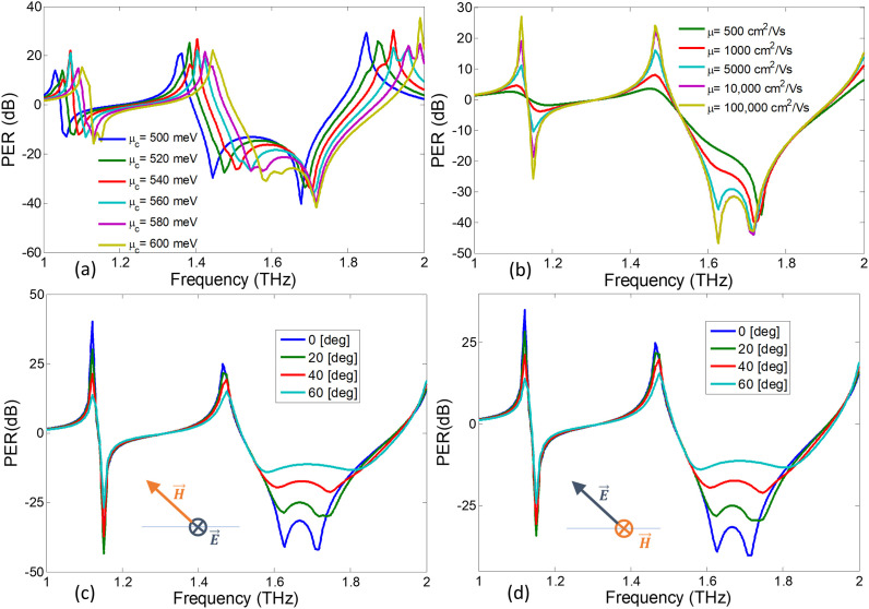
The surface conductivity of graphene layer depends on defect states, doping concentration and surface roughness of graphene layer. The well-known Kubo’s formula can be used to robustly model the response of surface conductivity of graphene due to variation in doping concentration [[52], [53], [54], [55], [56]]. The chemical potential of graphene layer varies due to doping concentration of the fabricated graphene layer. Fig. 5 (a) shows that the output spectra experiences a blue-shift in its resonance response due to the increase in from 500 meV to 600 meV. It is therefore important to control the electronic properties of graphene layer, particularly its chemical potential in order to correctly calibrate the response of the biosensor. Although the simulations assume the default value of meV, the sensor can still be recalibrated for other values of .
Fig. 5.
The PER spectrum in dB units showing the efficiency of circular polarization conversion for (a) various values of chemical potential (), (b) various values of electron mobility (μ). Polarization Extinction Ratio (PER) under oblique incidence angles for (c) TE and (d) TM conditions.
The intrinsic losses in graphene layers play an important role in achieving chiral reflection characteristics. At THz frequencies the electron mobility and chemical potential of graphene control the damping coefficient. On one hand, the chemical potential depends on doping concentration and external electrostatic bias of graphene. On the other hand, the electron’s mobility depends on fabrication process, i.e., is achieved for chemical vapor potential (CVD) [57] while may be achieved for suspended graphene at low temperatures [58]. The optical losses in graphene layer rely on the electron’s mobility (μ). Fig. 5(b) shows the effect of variation in chiral reflection characteristics due to change in electron mobility (ranging from ). It is clear that the magnitude of circular Polarization Extinction Ratio (PER) declines with the decrease in electron mobility (i.e., increase in damping coefficient). Therefore, the performance of the graphene-based polarization state sensor can may deteriorate due to unexpectedly high damping in graphene layer. Nevertheless, it should be emphasized that for average mobilities of the order of or , i.e., largely accessible in nowadays experimental setups, the desired effect is clearly and strongly obtained [59].
The response of graphene metasurfaces is evaluated under normal incidence for transverse Electric and Magnetic (TEM) fields conditions. However, it would be interesting to evaluate the sensor’s response at oblique incidence conditions. For instance, for the case of oblique incidence, the incident wave is assumed to be TE (incident electric field vector parallel to the metasurface) having no polarization component falls along the z-axis. As a result, it is clear from Fig. 5(c) that the induced circular dichroism (shown by PER) remains stable for the range of incident angles between 0 and 60°. Similarly, Fig. 5(d) shows that the incident wave assumed to be TM (incident magnetic field vector parallel to the metasurface) also shows stable PER spectrum for range of incident angles between 0 and 60°.
4. Biosensor’s calibration for virus sensing
The calibration of a measurement method is important in order to relate the measurement results to the complex refractive index (), which is the sum of the real refractive index (n) and the imaginary extinction coefficient κ. In the conventional Spectroscopic Ellipsometry [60,61], the measured polarization states are compared with a theoretical model such as Lorentz or Drude Model to determine the complex refractive index of the sample. For the proposed method, a characteristic calibration model for a particular metasurface is derived employing full-wave simulations. Two types of calibration curves related to the determination of the real and imaginary parts of the refractive index are discussed below.
4.1. Calibration model for refractive index sensing
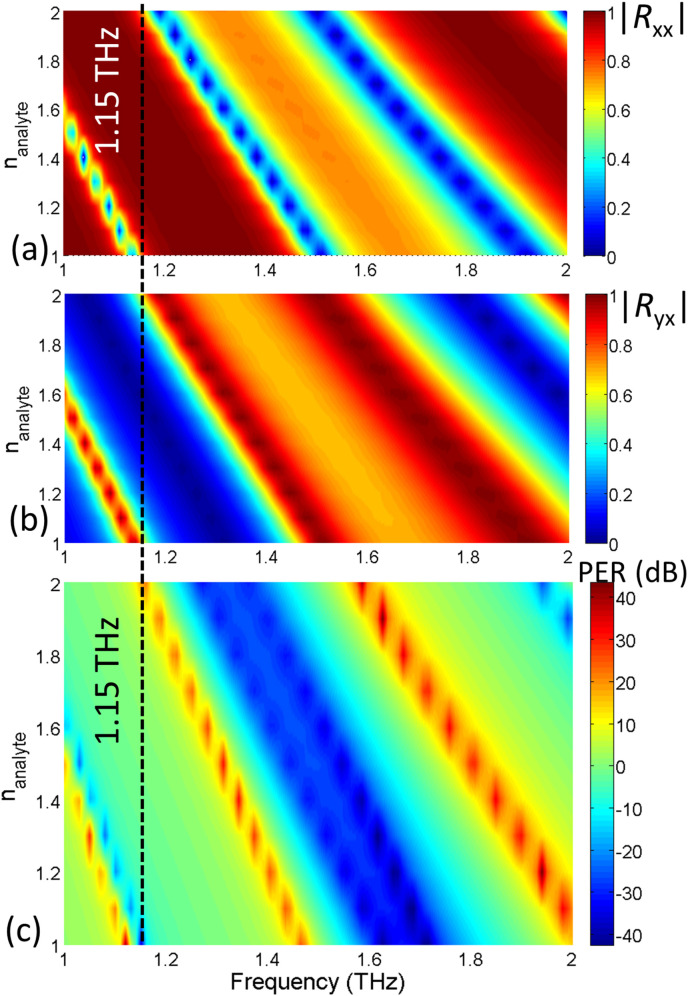
Virus analytes consists of antibody or bioreceptor proteins that selectively binds with target antigen or virus [5,9]. Conventionally, the small absorption cross section and nearly identical optical properties make viruses difficult to discriminate using traditional optical spectroscopic techniques. In Fig. 2, the analyte is shown to be deposited on top of the metasurface for detection. Numerically, the situation is modelled by assuming a superstrate of thickness 5 μm with a RI equal to that of the analyte. In the presence of the superstrate of , there is a reduction of the phase velocity of the reflected electromagnetic waves leading to larger phase shifts at a specific frequency. Hence, the reflected co- and cross coefficient spectra (Fig. 3) and the PER curve (Fig. 4) would experience a ref-shift i.e. all the resonant peaks would shift towards lower frequencies.
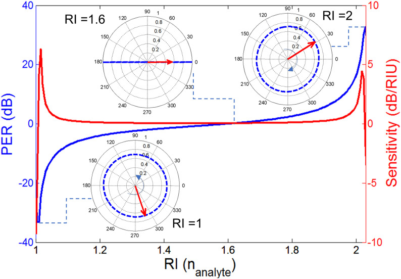
The relation between the increased refractive index and the metasurface response is numerically characterized by varying the RI of the analyte () between 1 and 2 and determining the reflection coefficients i.e., and and the PER. Fig. 6 (a)-(c) summarizes the characteristic calibration model of the graphene metasurface. By examining the calibration model, optical RI of a viruses can be interpreted. As anticipated, a clear red-shift can be noted in the spectra of reflection coefficients and PER. The sensing frequency is selected based on the metasurfaces’ sensitivity to the PER change for a given range of RIs. For example at 1.15 THz, as shown in Fig. 6 by a dotted line, a PER variation from a large negative value to a large positive is observed when the RIs varies between 1 and 2. At these two extreme PER values, note that co- and cross polarized components attain the half-power magnitudes i.e. . The one-dimensional plot which is extracted from the surface distribution at 1.15 THz (see Fig. 7 ) shows the PER variation in a clearer manner. As depicted in the figure, the PER peaks with a negative polarity of −30 when = 1 and the corresponding polarization is LH circular. Between this negative peak and the positive peak of +32 dB when the electric field is RHC, the PER curve crosses zero where the polarization becomes linear, as shown in the inset of Fig. 7. It can also be noted in Fig. 7 that the sensitivity is highest close to the two PER peaks where the polarization rapidly varies from circular to elliptical and then to linear. It is in this region of high sensitivity (large ) where the metasurface is capable of differentiating virus elements of close optical parameters.
Fig. 6.
The response of the graphene metasurface showing amplitude of (a) co- and (b) cross- polarization components of reflected field coefficients for the varying RI of analyte () and (c) PER spectrum derived from (a) and (b). Color-bars are included to represent the varying scale of reflection coefficients.
Fig. 7.
Variation of PER (dB) and sensitivity (dB/RIU) at fixed frequency of 1.15 THz with the change in the value of real part of the analyte’s refractive index. The inset shows the contour path traversed by locus tip of electric field vector in time at RI = 1, 1.6, 2 respectively.
4.2. Calibration model for extinction coefficient (κ) sensing
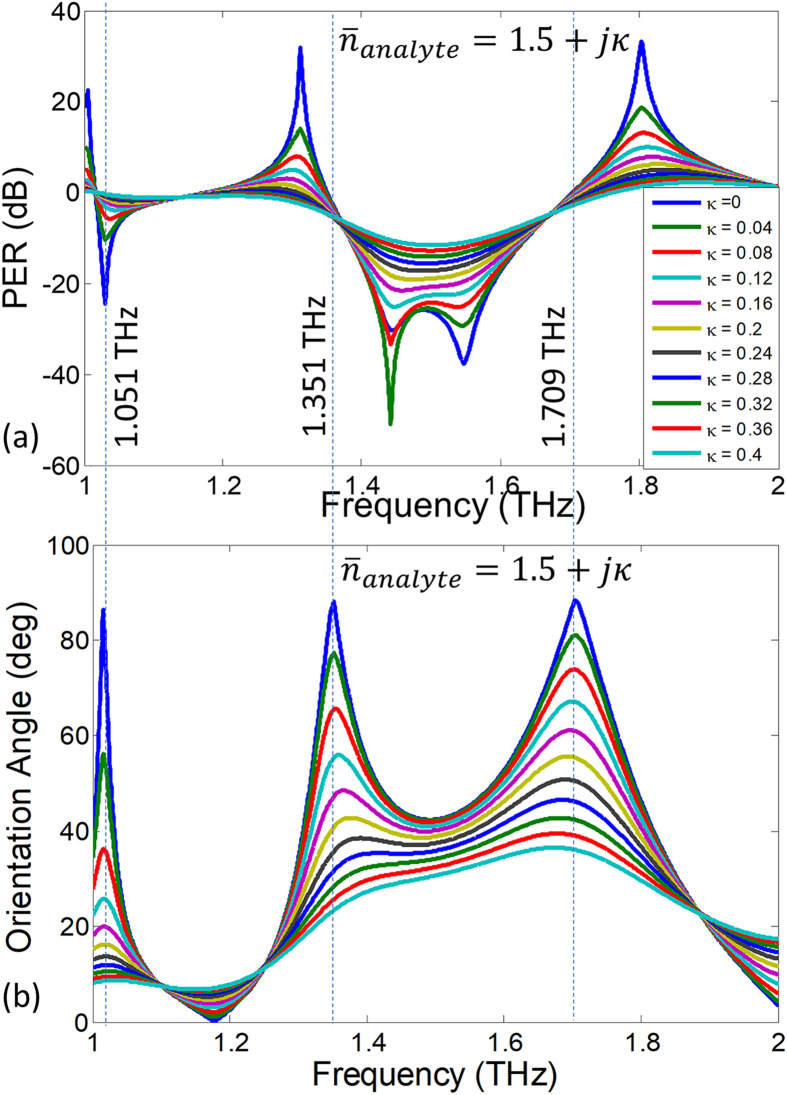
In many cases the biomolecules closely match in their refractive index (RI) and only slightly differ in their absorption characteristics which are related to the extinction coefficient κ. Here we show that for a fixed RI, the extinction coefficient is related to the orientation angle (τ) of the polarization ellipse, which is defined as the angle between the X-axis and the major axis. Mathematically,
| (5) |
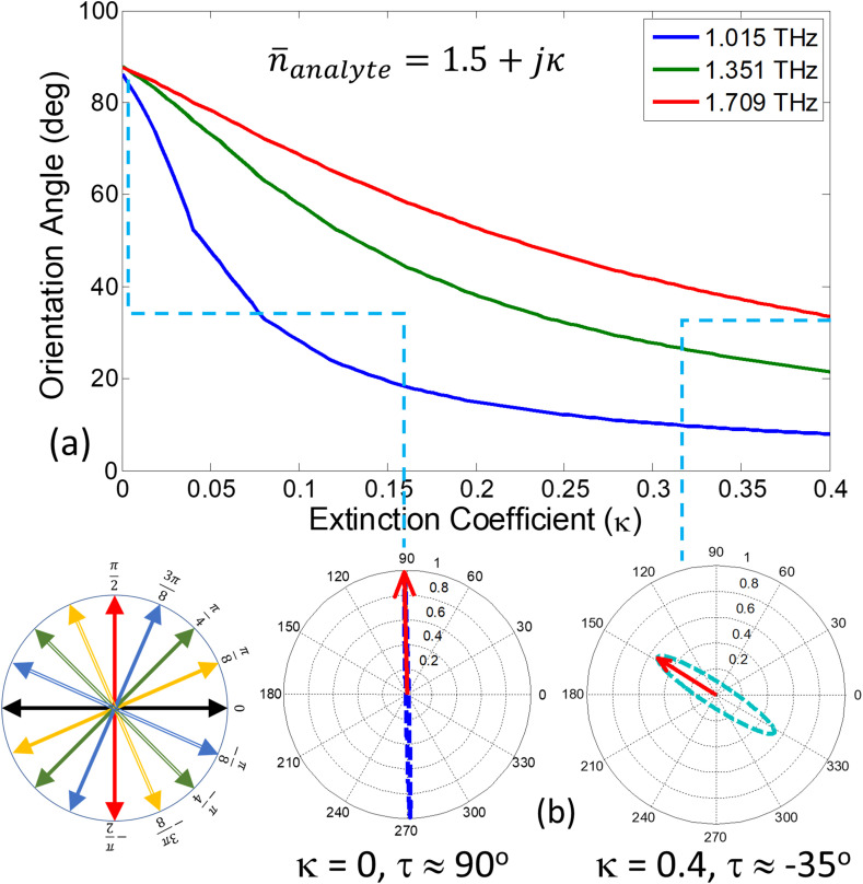
where δ is the phase difference between the co- and cross-polarized reflection coefficients ( and ). It follows from above equation that if the polarization is circular, and it is for fully cross-polarized fields (i.e. when ). Fig. 8 (a) provides the PER spectra when the RI (real part of the index) is fixed at 1.5 and the extinction coefficient (κ) is numerically varied between 0 and 0.4. Due to the increased losses, the reduction in PER values is evident at all the frequencies. In particular, note that for the higher extinction coefficients (such as ), the PER is not only reduced but there is also a frequency shift of its peak value indicating that the ellipticity of the polarization states has also changed. To show this interesting effect more clearly, the orientation angles of the underlying polarization states are extracted from the reflection coefficients using Eq. (5) and are plotted as function of frequency in Fig. 8 (b). The induced cross polarized fields on graphene metasurface i.e., are very sensitive to damping losses in the surrounding medium (due to strong evanescent fields around graphene). It is clear from the plotted graph that the orientation angle tilts towards the incident polarization axis i.e., x-axis with the increasing extinction coefficient. This phenomenon is more pronounced at the frequencies at which the co-polarized reflection is zero and the orientation angles vary rapidly with change in the extinction coefficient. Looking at Fig. 8 (b), we identify three discrete frequencies 1.015, 1.351 and 1.709 THz at which the orientation angles are highly sensitive to the change in the extinction coefficient. To characterize the dependence, the orientation angles (τ) are extracted from Fig. 8 (b) for discrete frequencies and are plotted as calibration curves for κ detection in Fig. 9 (a). The associated polarization states are plotted for two extinction coefficients at 1.709 THz and are given in Fig. 9(b). With the increase of extinction coefficient, the polarization state changes from fully cross-polarized for to elliptically polarized with an orientation tilt of for .
Fig. 8.
Variation in (a) PER and (b) orientation angle of the polarization ellipse due to change in extinction coefficient.
Fig. 9.
(a) Changes in orientation angle as κ is increased from 0 to 0.4 calculated at the frequencies where dominant power is reflected as cross-polarized fields. (b) The contour path traversed by locus tip of electric field vector in time at fixed frequency of 1.7 THz for and . Inset provides the schematic illustration of orientation angle (τ) for the polarization ellipse.
5. Virus sensing with the chiral biosensor
We present polarization sensing of closely related influenza viruses by numerically detecting the molecule specific ligands. The optical properties of influenza viruses have been characterized and are available in literature [34]. The sensing method can be readily extended to other deadly viruses such as the recently identified, SARS-CoV-2 whose complex refractive index is yet to be determined. The refractive index of influenza-related viruses depends on the protein concentration and the sample volume. The presence of immobilized binding ligands on top of metasurface are required for selective detection of biomolecules. It is expected that the binding ligands even without inoculation of any virus may dampen the surface plasmon due to its coupling with strong evanescent fields surrounding graphene metasurface. The optical properties of influenza virus samples are available for several strains at THz frequencies [34]. Recently, the complex refractive index of three different types of influenza viruses are retrieved using on THz spectroscopy [34]. Special care was given to avoid measurement error for effective refractive indexes due to strong water absorption peak at THz frequencies. Analytically, the dispersive refractive index () is obtained by taking the square root of the complex permittivity given by the well-known Drude-Lorentz model:
| (6) |
Here, = 4 THz is the plasma frequency, THz is the resonant frequency, and γ = 4 THz is the damping coefficient. the The Drude-Lorentz model in eq. (6) show that the binding energy for all the influenza virus strains lies in the THz frequency range. Defining the complex refractive index as , the scaling coefficients A and B for three virus strains are provided in Table 2 for a given protein concentration level. It is noted that increasing the virus concentration levels leads to an increase in the extinction coefficient (κ) due to the overall increase in the absolute absorption [34].
Table 2.
Optical Properties of three different strains of Influenza viruses for specific protein concentration [34].
| Influenza Virus Subtype | Strain Name | Protein Concentration | Refractive Index An + B |
|---|---|---|---|
| A/NWS/1933 | H1N1 | 0.54 (mg/ml) | A = 1, B = 1.4 |
| A/Wild bird/Korea/K09-652/2009 | H5N2 | 0.2 (mg/ml) | A = 1, B = 1 |
| A/Korean native chicken/Korea/k040110/2010 | H9N2 | 0.28 (mg/ml) | A = 1.2, B = 1.4 |
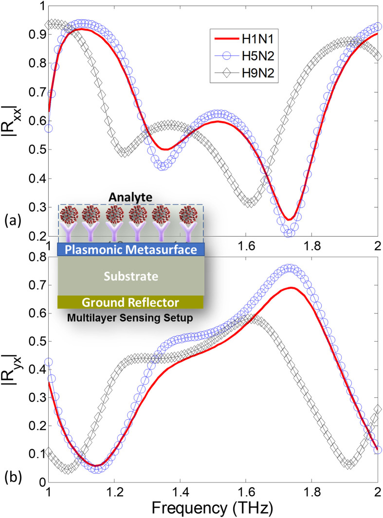
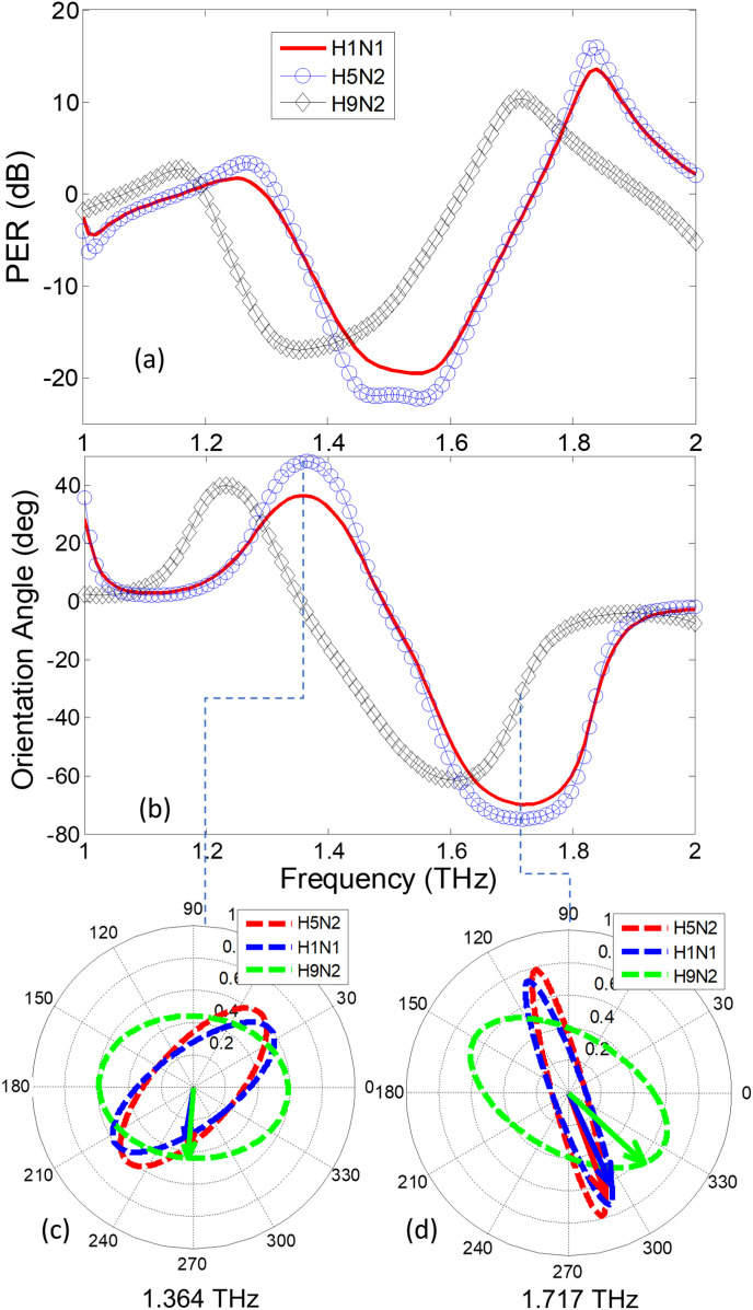
In the polarization detection set-up of Fig. 2, the analyte is numerically laid as a 5 μm thick superstrate layer on the surface of the Biosensor. The complex refractive index of the superstrate is assumed to be . Assuming an x-directed incident wave, the co- () and cross- polarized reflection coefficients for the H1N1, H5N2 and H9N2 strains are determined using COMSOL full-wave package and are given in Fig. 10 (a)-(b). Note that the conventional reflector-based sensing that rely only on the reflection coefficient scan would not be able to clearly distinguish the three strains. Particularly, the spectral responses of H1N1 and H5N2 strains are closely matched because they have the same RI with a minor difference in the extinction coefficient κ (see Table 2). However, when the PER spectrum is retrieved and the orientation angles of the resulting polarization states are calculated in Fig. 11 , the three strains show a clear difference of polarization states. The polarization states of the three strains are shown at two resonant frequencies 1.364 and 1.717 THz in Fig. 11 (c) and (d). The difference between H9N2 and the other two strains is clearly apparent because the significant variation in the real part of the refractive index (n). The H1N1 and H5N2 viruses are isolated on the basis of the ellipse orientation resulting from difference in the κ values. Hence the proposed method is able to distinguish minute variation in the extinction coefficient (κ) by determination of an additional parameter (the angle τ). Finally, looking again at the polarization states in Fig. 11, note that the excessive tilt in the H1N1 ellipse is to due to higher losses in its analyte (B = 1.4) compared to the H5N2 which incorporates low losses (B = 1). It can be noted that the polarization ellipse at resonance frequency of 1.364 THz is oriented along , and for H9N2 (LH), H1N1 (RH) and H5N2 (RH) virus strains respectively. Similarly, the polarization ellipse at resonance frequency of 1.717 THz can also be distinguished based on orientation of , and for H9N2 (RH), H1N1 (RH) and H5N2 (RH) virus strains respectively. This clearly shows the utility of the monochromatic polarization sensitive sensing technique to when compared to LSPR resonance shift based biosensing techniques. The time varying change in electric field vector along with the polarization ellipse for all the three virus strains i.e., H1N1, H5N2 and H9N2 can be seen in the accompanying supplementary material.
Fig. 10.
Magnitude response of (a) co-polarized (b) cross-polarized reflection coefficients of the sensor for three different strains of Influenza viruses H1N1, H5N2 and H9N2. Inset shows multilayer sensing setup with top layer as virus sample under test (analyte).
Fig. 11.
(a) PER and (b) Orientation angle spectrum for three different strains of influenza viruses H1N1, H5N2 and H9N2. The contour path traversed by locus tip of electric field vector in time at fixed frequency of (c) 1.364 THz and (d) 1.717 THz for all three strains of viruses.
6. Conclusion
Recently, COVID-19 has been declared as pandemic and testing of its low concentrations is one of the key steps to stop virus contagion. In this paper, we provide a comprehensive detection technique based on polarization-state sensing that can distinguish virus elements with closely resembling optical properties. The measurement set-up of the polarization state sensing consists of a graphene-based plasmonic metasurface with chiral unit cells. Therefore, the reflected electric fields have polarization states that are highly sensitive to the refractive index of the dielectric surrounding the resonant unit cells. When a virus analyte is deposited on the metasurface, the polarization state changes according to its complex dielectric constant. It is shown that the proposed sensor can distinguish three extremely similar influenza virus H1N1, H5N2, and H9N2 based on the variation of the reflected polarization states. We anticipate that the proposed polarization-based sensing using metasurfaces can potentially isolate viruses because its ability to distinguish between analytes of identical optical properties based on the extinction coefficient (κ) sensing.
CRediT authorship contribution statement
M. Amin: Conceptualization, Methodology, Software, Data curation, Writing - original draft. O. Siddiqui: Conceptualization, Formal analysis, Writing - original draft. H. Abutarboush: Visualization, Supervision, Project administration, Funding acquisition. M. Farhat: Resources, Software. R. Ramzan: Supervision.
Declaration of competing interest
The authors declare that they have no known competing financial interests or personal relationships that could have appeared to influence the work reported in this paper.
Acknowledgements
This project was supported by Deanship of Scientific Research at Taibah University under Research Grant number ENG-1.
Footnotes
Supplementary data to this article can be found online at https://doi.org/10.1016/j.carbon.2021.02.051.
Appendix A. Supplementary data
The following are the Supplementary data to this article:
References
- 1.Dalal A., Mohan H., Prasad M., Pundir C. Detection methods for influenza a h1n1 virus with special reference to biosensors: a review. Biosci. Rep. 2020;40(2) doi: 10.1042/BSR20193852. BSR20193852. [DOI] [PMC free article] [PubMed] [Google Scholar]
- 2.Funari R., Chu K.-Y., Shen A.Q. Detection of antibodies against sars-cov-2 spike protein by gold nanospikes in an opto-microfluidic chip. Biosens. Bioelectron. 2020:112578. doi: 10.1016/j.bios.2020.112578. [DOI] [PMC free article] [PubMed] [Google Scholar]
- 3.Moitra P., Alafeef M., Dighe K., Frieman M., Pan D. Selective naked-eye detection of sars-cov-2 mediated by n gene targeted antisense oligonucleotide capped plasmonic nanoparticles. ACS Nano. 2020;14.6:7617–7627. doi: 10.1021/acsnano.0c03822. [DOI] [PMC free article] [PubMed] [Google Scholar]
- 4.Qiu G., Gai Z., Tao Y., Schmitt J., Kullak-Ublick G.A., Wang J. Dual-functional plasmonic photothermal biosensors for highly accurate severe acute respiratory syndrome coronavirus 2 detection. ACS Nano. 2020;14(5):5268–5277. doi: 10.1021/acsnano.0c02439. [DOI] [PubMed] [Google Scholar]
- 5.Seo M., Park H.-R. Terahertz biochemical molecule-specific sensors. Advanced Optical Materials. 2020;8(3):1900662. [Google Scholar]
- 6.Luan J., Seth A., Gupta R., Wang Z., Rathi P., Cao S., Derami H.G., Tang R., Xu B., Achilefu S., et al. Ultrabright fluorescent nanoscale labels for the femtomolar detection of analytes with standard bioassays. Nature Biomedical Engineering. 2020;4(5):518–530. doi: 10.1038/s41551-020-0547-4. [DOI] [PMC free article] [PubMed] [Google Scholar]
- 7.Liu J., Jalali M., Mahshid S., Wachsmann-Hogiu S. Are plasmonic optical biosensors ready for use in point-of-need applications? Analyst. 2020;145(2):364–384. doi: 10.1039/c9an02149c. [DOI] [PubMed] [Google Scholar]
- 8.Zhang S., Wong C.L., Zeng S., Bi R., Tai K., Dholakia K., Olivo M. Metasurfaces for biomedical applications: imaging and sensing from a nanophotonics perspective. Nanophotonics. 07 Sep. 2020:20200373. doi: 10.1515/nanoph-2020-0373. https://www.degruyter.com/view/journals/nanoph/ahead-of-print/article-10.1515-nanoph-2020-0373/article-10.1515-nanoph-2020-0373.xml (0) [DOI] [Google Scholar]
- 9.Syahir A., Usui K., Tomizaki K.-y., Kajikawa K., Mihara H. Label and label-free detection techniques for protein microarrays. Microarrays. 2015;4(2):228–244. doi: 10.3390/microarrays4020228. [DOI] [PMC free article] [PubMed] [Google Scholar]
- 10.Yoo H., Shin J., Sim J., Cho H., Hong S. Reusable surface plasmon resonance biosensor chip for the detection of h1n1 influenza virus. Biosens. Bioelectron. 2020;168:112561. doi: 10.1016/j.bios.2020.112561. [DOI] [PubMed] [Google Scholar]
- 11.Su F., Jia Q., Li Z., Wang M., He L., Peng D., Song Y., Zhang Z., Fang S. Aptamer-templated silver nanoclusters embedded in zirconium metal–organic framework for targeted antitumor drug delivery. Microporous Mesoporous Mater. 2019;275:152–162. [Google Scholar]
- 12.Jia Q., Li Z., Guo C., Huang X., Kang M., Song Y., He L., Zhou N., Wang M., Zhang Z., et al. Pegma-modified bimetallic nico prussian blue analogue doped with tb (iii) ions: efficiently ph-responsive and controlled release system for anticancer drug. Chem. Eng. J. 2020;389:124468. [Google Scholar]
- 13.Lin J., Cai X., Liu Z., Liu N., Xie M., Zhou B., Wang H., Guo Z. Anti-liquid-interfering and bacterially antiadhesive strategy for highly stretchable and ultrasensitive strain sensors based on cassie-baxter wetting state. Adv. Funct. Mater. 2020;30(23):2000398. [Google Scholar]
- 14.Lin J., Wang Y., Wei X., Kong S., Liu Z., Liu J., Zhang F., Lin S., Ji B., Zhou Z., et al. Controllable antibacterial and bacterially anti-adhesive surface fabricated by a bio-inspired beetle-like macromolecule. Int. J. Biol. Macromol. 2020;157:553–560. doi: 10.1016/j.ijbiomac.2020.04.207. [DOI] [PubMed] [Google Scholar]
- 15.Duan F., Hu M., Guo C., Song Y., Wang M., He L., Zhang Z., Pettinari R., Zhou L. Chromium-based metal-organic framework embedded with cobalt phthalocyanine for the sensitively impedimetric cytosensing of colorectal cancer (ct26) cells and cell imaging. Chem. Eng. J. 2020:125452. [Google Scholar]
- 16.Wang M., Hu M., Liu J., Guo C., Peng D., Jia Q., He L., Zhang Z., Du M. Covalent organic framework-based electrochemical aptasensors for the ultrasensitive detection of antibiotics. Biosens. Bioelectron. 2019;132:8–16. doi: 10.1016/j.bios.2019.02.040. [DOI] [PubMed] [Google Scholar]
- 17.Baum C.E. Fast Electrical and Optical Measurements. Springer; 1986. Electromagnetic sensors and measurement techniques; pp. 73–144. [Google Scholar]
- 18.Liu Z., Wang L., Hua M., Liu X., Qian F., Xie G., Ning Y., Shi Y., Wang X., Yang F. High-q metamaterials based on cavity mode resonance for thz sensing applications. AIP Adv. 2020;10(7) 075014. [Google Scholar]
- 19.Amin M., Farhat M., Bağcı H. An ultra-broadband multilayered graphene absorber. Optic Express. 2013;21(24):29938–29948. doi: 10.1364/OE.21.029938. [DOI] [PubMed] [Google Scholar]
- 20.M. Amin, M. Farhat, H. Bağci, A Dynamically Reconfigurable Fano Metamaterial through Graphene Tuning for Switching and Sensing Applications 3. [DOI] [PMC free article] [PubMed]
- 21.Bhattarai K., Silva S., Song K., Urbas A., Lee S.J., Ku Z., Zhou J. Metamaterial perfect absorber analyzed by a meta-cavity model consisting of multilayer metasurfaces. Sci. Rep. 2017;7(1):1–9. doi: 10.1038/s41598-017-10520-w. [DOI] [PMC free article] [PubMed] [Google Scholar]
- 22.Matsunaga T., Hishiya T., Takeuchi T. Surface plasmon resonance sensor for lysozyme based on molecularly imprinted thin films. Anal. Chim. Acta. 2007;591(1):63–67. doi: 10.1016/j.aca.2007.02.072. [DOI] [PubMed] [Google Scholar]
- 23.O’Shannessy D.J., Brigham-Burke M., Peck K. Immobilization chemistries suitable for use in the biacore surface plasmon resonance detector. Anal. Biochem. 1992;205(1):132–136. doi: 10.1016/0003-2697(92)90589-y. [DOI] [PubMed] [Google Scholar]
- 24.Das C.M., Guo Y., Kang L., Ho H.-p., Yong K.-T. Investigation of plasmonic detection of human respiratory virus. Advanced Theory and Simulations. 2020;3(7):2000074. doi: 10.1002/adts.202000074. https://onlinelibrary.wiley.com/doi/pdf/10.1002/adts.202000074 https://onlinelibrary.wiley.com/doi/abs/10.1002/adts.202000074 arXiv. [DOI] [PMC free article] [PubMed] [Google Scholar]
- 25.Altintas Z., Gittens M., Guerreiro A., Thompson K.-A., Walker J., Piletsky S., Tothill I.E. Detection of waterborne viruses using high affinity molecularly imprinted polymers. Anal. Chem. 2015;87(13):6801–6807. doi: 10.1021/acs.analchem.5b00989. [DOI] [PubMed] [Google Scholar]
- 26.Shi L., Sun Q., He J., Xu H., Liu C., Zhao C., Xu Y., Wu C., Xiang J., Gu D., et al. Development of spr biosensor for simultaneous detection of multiplex respiratory viruses. Bio Med. Mater. Eng. 2015;26(s1):S2207–S2216. doi: 10.3233/BME-151526. [DOI] [PubMed] [Google Scholar]
- 27.Keshavarz A., Vafapour Z. Sensing avian influenza viruses using terahertz metamaterial reflector. IEEE Sensor. J. 2019;19(13):5161–5166. [Google Scholar]
- 28.Moon G., Choi J.-r., Lee C., Oh Y., Kim K., Kim D. Machine learning-based design of meta-plasmonic biosensors with negative index metamaterials. Biosens. Bioelectron. 2020:112335. doi: 10.1016/j.bios.2020.112335. [DOI] [PubMed] [Google Scholar]
- 29.Yanik A.A., Huang M., Kamohara O., Artar A., Geisbert T.W., Connor J.H., Altug H. An optofluidic nanoplasmonic biosensor for direct detection of live viruses from biological media. Nano Lett. 2010;10(12):4962–4969. doi: 10.1021/nl103025u. [DOI] [PMC free article] [PubMed] [Google Scholar]
- 30.Goldsmith B.R., Locascio L., Gao Y., Lerner M., Walker A., Lerner J., Kyaw J., Shue A., Afsahi S., Pan D., et al. Digital biosensing by foundry-fabricated graphene sensors. Sci. Rep. 2019;9(1):434. doi: 10.1038/s41598-019-38700-w. [DOI] [PMC free article] [PubMed] [Google Scholar]
- 31.Li N., Tittl A., Yue S., Giessen H., Song C., Ding B., Liu N. Dna-assembled bimetallic plasmonic nanosensors, Light. Science & Applications. 2014;3(12):e226. [Google Scholar]
- 32.Padilla W.J., Fan K., Suen J.Y., Liu X. Optical Sensors. Optical Society of America; 2018. All-dielectric metasurfaces for thz imaging and sensing. SeW3J–3. [Google Scholar]
- 33.Osborne I.S. 2018. Metasurfaces for Molecular Detection. [Google Scholar]
- 34.Lee D.-K., Kang J.-H., Kwon J., Lee J.-S., Lee S., Woo D.H., Kim J.H., Song C.-S., Park Q.-H., Seo M. Nano metamaterials for ultrasensitive terahertz biosensing. Sci. Rep. 2017;7(1):1–6. doi: 10.1038/s41598-017-08508-7. [DOI] [PMC free article] [PubMed] [Google Scholar]
- 35.Sakhdari M., Farhat M., Chen P.-Y. Pt-symmetric metasurfaces: wave manipulation and sensing using singular points. New J. Phys. 2017;19(6) 065002. [Google Scholar]
- 36.Zhu Y., Li Z., Hao Z., DiMarco C., Maturavongsadit P., Hao Y., Lu M., Stein A., Wang Q., Hone J., et al. Optical conductivity-based ultrasensitive mid-infrared biosensing on a hybrid metasurface. Light Sci. Appl. 2018;7(1):67. doi: 10.1038/s41377-018-0066-1. [DOI] [PMC free article] [PubMed] [Google Scholar]
- 37.Lee Y., Kim S.-J., Park H., Lee B. Metamaterials and metasurfaces for sensor applications. Sensors. 2017;17(8):1726. doi: 10.3390/s17081726. [DOI] [PMC free article] [PubMed] [Google Scholar]
- 38.Kim H.K., Lee D., Lim S. A fluidically tunable metasurface absorber for flexible large-scale wireless ethanol sensor applications. Sensors. 2016;16(8):1246. doi: 10.3390/s16081246. [DOI] [PMC free article] [PubMed] [Google Scholar]
- 39.Tanasković D., Obradov M., Jakšić O., Jakšić Z. Nonlocal effects in double fishnet metasurfaces nanostructured at deep subwavelength level as a path toward simultaneous sensing of multiple chemical analytes. Photonics and Nanostructures-Fundamentals and Applications. 2016;18:36–42. [Google Scholar]
- 40.Oka T., Aoki H. Photovoltaic hall effect in graphene. Phys. Rev. B. 2009;79(8) 081406. [Google Scholar]
- 41.Jing P., Wang Q., Wang B., Gao X., Zhang Y., Wu H. Encapsulating yolk-shell fes2@ carbon microboxes into interconnected graphene framework for ultrafast lithium/sodium storage. Carbon. 2020;159:366–377. [Google Scholar]
- 42.Islam M., Sultana J., Biabanifard M., Vafapour Z., Nine M., Dinovitser A., Cordeiro C., Ng B.-H., Abbott D. Tunable localized surface plasmon graphene metasurface for multiband superabsorption and terahertz sensing. Carbon. 2020;158:559–567. [Google Scholar]
- 43.Patil P.O., Pandey G.R., Patil A.G., Borse V.B., Deshmukh P.K., Patil D.R., Tade R.S., Nangare S.N., Khan Z.G., Patil A.M., et al. Graphene-based nanocomposites for sensitivity enhancement of surface plasmon resonance sensor for biological and chemical sensing: a review. Biosens. Bioelectron. 2019;139:111324. doi: 10.1016/j.bios.2019.111324. [DOI] [PubMed] [Google Scholar]
- 44.Suvarnaphaet P., Pechprasarn S. Graphene-based materials for biosensors: a review. Sensors. 2017;17(10):2161. doi: 10.3390/s17102161. [DOI] [PMC free article] [PubMed] [Google Scholar]
- 45.Chowdhury A.D., Nasrin F., Gangopadhyay R., Ganganboina A.B., Takemura K., Kozaki I., Honda H., Hara T., Abe F., Park S., et al. Controlling distance, size and concentration of nanoconjugates for optimized lspr based biosensors. Biosens. Bioelectron. 2020:112657. doi: 10.1016/j.bios.2020.112657. [DOI] [PubMed] [Google Scholar]
- 46.Amin M., Siddiqui O., Farhat M. Linear and circular dichroism in graphene-based reflectors for polarization control. Physical Review Applied. 2020;13(2) 024046. [Google Scholar]
- 47.Amin M., Siddiqui O., Farhat M. Metasurface supporting broadband circular dichroism for reflected and transmitted fields simultaneously. J. Phys. Appl. Phys. 2020;53(43):435106. [Google Scholar]
- 48.Zhang Y., Feng Y., Zhao J. Graphene-enabled tunable multifunctional metamaterial for dynamical polarization manipulation of broadband terahertz wave. Carbon. 2020;163:244–252. [Google Scholar]
- 49.Wei L., Yu L., Jiaoqi H., Guorong H., Yang Z., Weiling F. Application of terahertz spectroscopy in biomolecule detection. Frontiers in Laboratory Medicine. 2018;2(4):127–133. [Google Scholar]
- 50.Davies C.L., Patel J.B., Xia C.Q., Herz L.M., Johnston M.B. Temperature-dependent refractive index of quartz at terahertz frequencies. J. Infrared, Millim. Terahertz Waves. 2018;39(12):1236–1248. [Google Scholar]
- 51.Kim T.-T., Oh S.S., Kim H.-D., Park H.S., Hess O., Min B., Zhang S. Electrical access to critical coupling of circularly polarized waves in graphene chiral metamaterials. Science advances. 2017;3(9) doi: 10.1126/sciadv.1701377. [DOI] [PMC free article] [PubMed] [Google Scholar]
- 52.Hanson G.W. Dyadic green’s functions and guided surface waves for a surface conductivity model of graphene. J. Appl. Phys. 2008;103(6) 064302. [Google Scholar]
- 53.Jablan M., Buljan H., Soljačić M. Plasmonics in graphene at infrared frequencies. Phys. Rev. B. 2009;80(24):245435. [Google Scholar]
- 54.Vakil A., Engheta N. Transformation optics using graphene. Science. 2011;332(6035):1291–1294. doi: 10.1126/science.1202691. [DOI] [PubMed] [Google Scholar]
- 55.Koppens F.H., Chang D.E., Garcia de Abajo F.J. Graphene plasmonics: a platform for strong light–matter interactions. Nano Lett. 2011;11(8):3370–3377. doi: 10.1021/nl201771h. [DOI] [PubMed] [Google Scholar]
- 56.Garcia de Abajo F.J. Graphene plasmonics: challenges and opportunities. ACS Photonics. 2014;1(3):135–152. [Google Scholar]
- 57.Li X., Magnuson C.W., Venugopal A., Tromp R.M., Hannon J.B., Vogel E.M., Colombo L., Ruoff R.S. Large-area graphene single crystals grown by low-pressure chemical vapor deposition of methane on copper. J. Am. Chem. Soc. 2011;133(9):2816–2819. doi: 10.1021/ja109793s. [DOI] [PubMed] [Google Scholar]
- 58.Castro E.V., Ochoa H., Katsnelson M., Gorbachev R., Elias D., Novoselov K., Geim A., Guinea F. Limits on charge carrier mobility in suspended graphene due to flexural phonons. Phys. Rev. Lett. 2010;105(26):266601. doi: 10.1103/PhysRevLett.105.266601. [DOI] [PubMed] [Google Scholar]
- 59.Brown M.A., Crosser M.S., Leyden M.R., Qi Y., Minot E.D. Measurement of high carrier mobility in graphene in an aqueous electrolyte environment. Appl. Phys. Lett. 2016;109(9) 093104. [Google Scholar]
- 60.Fujiwara H. John Wiley and Sons Inc; 2007. Spectroscopic Ellipsometry Principles and Applications. [Google Scholar]
- 61.Azzam R., Bashara N. North Holland Publication; 1977. Ellipsometry and Polarized Light. [Google Scholar]
Associated Data
This section collects any data citations, data availability statements, or supplementary materials included in this article.


