

Abstract

Plasmonic nanolasers (spasers) are of intense interest, attributable to their ability to generate a high-intensity coherent radiation. We infiltrated a three-dimensional silica-based photonic crystal (PhC) film with spasers, composed of spherical gold cores, surrounded by silica shells with dye molecules. In spasers, the gold nanospheres supported the surface plasmons and the dye molecules transferred incoming optical energy to the surface plasmons. Our experiments show that such a structure, consisting of a PhC, which acts as an external distributed feedback resonator, and spasers, can serve as a coherent source of electromagnetic radiation. Spasers were locked in phase by the common radiation causing a phenomenon called the lasing spaser: the emission of spatially and temporarily coherent light normal to the surface of the PhC film. The far-field radiation patterns appeared in the shape of the Star-of-David, which is due to the dispersion along the Brillouin zone boundary. The infiltration of the spasers into the PhC led to drastic narrowing of the emission peak and an 80-fold decrease in the spaser generation threshold with respect to the same spasers in a suspension at room temperature.
Introduction
Although plasmonic effects have been known for more than a century, there is a tremendous interest in lasing nanoplasmonic systems, which benefit from the introduction of the spaser, a nanoscale source of localized optical fields proposed over a decade ago.1 It is analogous to the conventional laser but in a spaser, photons are replaced by surface plasmons, and the resonant cavity is replaced by a nanoparticle (NP), which supports the plasmonic modes.2 Spasers could find a wide range of applications, including nanoscale lithography, sensing and detection, nanoscopy, and biomedicine because they allow to overcome the diffraction limit and concentrate optical energy in hot spots much smaller than the wavelength.3,4 In 2009, Noginov et al. reported on the lasing (spasing) action of gold spheres in a dye-filled, glasslike shell immersed in a solution.5 The dye coupled to the gold nanospheres mediates the generation of surface plasmons when optically pumped. A similar nanoshell spaser design was utilized to develop the smallest spaser with only 22 nm in diameter utilizing an uranine dye; it was used for cancer theranostics.4
The realization of spasers in a solid-state thin layer makes it a very practical proposition. A number of surface plasmon spasers have been described.6−13 However, a small spaser produces light with little intensity and that light is not collimated into a narrow beam. Zhou et al. designed and demonstrated a plasmonic laser consisting of a periodic array of metal NPs covered with a nanolayer of an organic dye that served as its gain medium.6 Such a system shows characteristics of the lasing spaser, which has theoretically been proposed by Zheludev et al.7 It consists of a two-dimensional (2D) array of plasmonic nano-resonators combined with a layer of gain material, for example, an optically or electrically pumped semiconductor. As a result, synchronized by their interactions, the spasers are oscillating in phase and emitting coherent radiation. Although the constituent spasers may also generate in isolation, their inclusion into the lasing spaser reduces the generation threshold and increases the output power due to the induced coherence between the different spasers. This approach may be very attractive for integrated devices and high-power lasers.
Another demonstrated lasing plasmonic array is a plasmonic crystal consisting of nanoholes in a gold nanofilm over an InGaAs semiconductor gain medium.8 Recently, a spaser was experimentally demonstrated exhibiting a highly directional emission in the visible based on a periodic subwavelength-hole array fabricated in a metal film. These holes acted as plasmonic nanocavities, and an organic laser dye was used to supply gain.9 Further, theoretical proposals include novel plasmonic lasers based on the band edge modes of one-dimensional plasmonic crystals in an asymmetric dielectric environment.14 Another paper proposed a highly directional continuous-wave coherent light source.15 It was based on a 2D array of incoherently pumped spasers, which were shown to synchronize with each other. A theoretical study of the optical amplification in periodic arrays of subwavelength apertures incorporating optically pumped gain media was reported.16 Recently, a planar plasmonic 2D lattice with a honeycomb symmetry (viz., the symmetry of graphene), covered with a gain medium, has been demonstrated to produce amplified radiation.17 Recently, an array of ferromagnetic Ni nanodisks overlaid with an organic gain medium generating at visible wavelengths were proposed.18
In this article, we present lasing spasers (surface-plasmon-based lasers) in a three-dimensional (3D) photonic crystal (PhC). We experimentally show that by combining a PhC and spasers, a coherent source of electromagnetic radiation based on plasmonic oscillations can be created. We also demonstrate that a 3D PhC, infiltrated with plasmonic resonators supporting coherent plasmonic excitations with a high quality factor, can act as a source of spatially and temporally coherent radiation. In-phase plasmonic oscillations in the individual resonators lead to the emission of light propagating in the direction normal to the PhC film.
Results and Discussion
We used a system in which spasers based on gold NPs and an organic dye (uranine, fluorescein disodium salt dihydrate) (Figure 1a) were infiltrated into the matrix of monodisperse spherical silica particles (MSSPs). The size of the gold core was selected in such a way that its surface plasmon resonance peak position overlaps the emission spectra of uranine, which is a necessary condition for spaser generation. These MSSPs were packed into an ordered, face-centered cubic lattice structure forming a PhC film with a photonic band gap. The top view of this film is shown in Figure 1b. The stop band at the edge of the first Brillouin zone was chosen to match the dye emission frequency. The diameter of the MSSPs was chosen so that the Bragg reflection wavelength of the PhC films overlapped with the emission spectrum of the spasers. This configuration led to a feedback similar to distributed feedback (DFB) lasers. Consequently, the emitters (spasers) were generated in an external DFB cavity. Such a device may be called a lasing DFB spaser in analogy with the lasing spaser,7 a proposed planar source of spatially and temporally coherent radiation. In the lasing spaser, identical spasers interact through a common mode of radiation, which makes them oscillate (generate) in phase, producing a coherent radiation.15 Another similar but distinct spasing system reported recently is a DFB plasmonic laser where the spasing modes are surface plasmon polaritons, and the gain medium comprises semiconductor light-emitting diodes.19
Figure 1.

(a) TEM images of spasers; (b) SEM image of the top view of the PhC film (on a glass substrate); (c) SEM image of spasers infiltrated into a PhC (on a silicon substrate).
The spasers used in the present work consisted of a gold core and a silica shell with infiltrated dye molecules (uranine), with the size of the spasers being ∼35 nm. It should be noted that the thickness of the silica shell is optimized and a further increase in thickness did not lead to an enhancement of the optical characteristics of the spaser. The sub-micrometer silica spheres were synthesized by the Stöber method,20 and then the PhC films with a desired band gap were prepared by the dynamic meniscus method on a glass substrate (Figure S1).21 The resultant self-assembled spheres formed a PhC film with a hexagonal face-centered cubic symmetry (Figure 1b) with an entire thickness of 4–7 μm (Figure S2). Then, the spasers were infiltrated into a PhC matrix by impregnation and subsequent drying. The entire PhC structure was nearly quantitatively infiltrated by spasers through capillary forces (Figure 1c), which was confirmed by observing the entire sample under illumination. Note that for obtaining a better SEM image, we replaced the glass substrate with the more conductive silicon on which the PhC films grew rather disordered.
The PhC film on a glass substrate, infiltrated with the spasers, was pumped optically with an optical parametric oscillator at a wavelength of λp = 488 nm with 7 ns pulses. A glass hemisphere attached through an immersion liquid to the glass substrate allowed to register all the light rays coming from the PhC. Far-field patterns of the lasing intensity were registered on a screen after spectral filtration (Figure 2).
Figure 2.
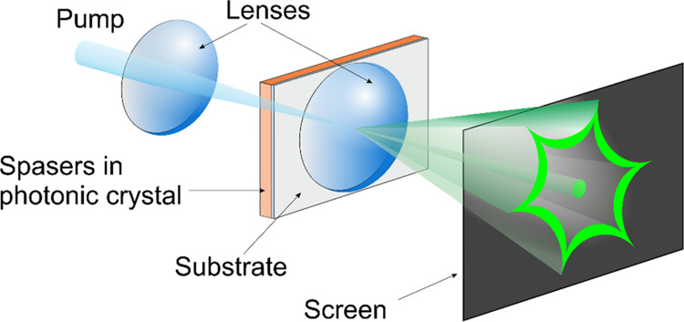
Experimental schematic. The far-field intensity distributions of the PhC lasing spaser were directly measured on a screen.
The emission from the opal structure above the threshold exhibited a pronounced six-fold “Star-of-David” pattern as shown in Figure 3a (the video of the spaser generation is available in the Supporting Information). The bright spot in the center of the image is caused by the pump laser beam. We tilted the sample to various angles with respect to the horizontal and vertical planes, but no differences in the emission were detected. In other words, this symmetric emission is not due to the scattering from the opal crystal because this feature does not depend on the direction of the incident laser beam. Note that the same emission pattern (with the same intensity) was observed from any location of the sample, confirming the uniform distribution of the spasers throughout the PhC. We also performed cross-sectional analyses by focused ion beam (FIB) and observed spasers at a depth of 2–3 μm, confirming the penetration of the spasers into the PhC.
Figure 3.

(a) Measured lasing spaser emission pattern from the sample imaged on the screen and the first Brillouin zone of the close-packed face-centered cubic structure. The W points shown correspond to the direction of the sixfold star-shaped emission pattern. (b) Frequency-angular distribution calculated using formula 1. The azimuthal angle φ is in the plane of the figure. X = sin(θ) cos(φ), Y = sin(θ) sin(φ), |φ – πm/3| ≤ π/6, m = 0, ±1, ±2, ±3. (c) Normalized (to unity at the maximum) (1) extinction of gold NPs; (2) spontaneous emission of uranine; (3) stimulated emission of spasers; (4) reflectance of the PhC at normal incidence. The emission spectrum (2) was measured at a low excitation intensity.
To provide a feedback necessary for the lasing spaser, a direct-propagating wave (say, in the ΓW-direction) and the back-propagating wave (in the ΓW-direction) should couple at the W-point or another high-symmetry point at the boundary of the PhC Brillouin zone. This coupling would create a band gap at the corresponding point (the W-point in our example). The examination of the dispersion of a PhC with the face-centered cubic structure built by the dense packing of dielectric spheres shows that such band gaps exist at the L-point and the W-, K-, and U-points but not at the X-points, as indicated in Figure 3a.22 Out of these points, only the six W-points possess the experimentally observed sixfold symmetry. These six points belong to a hexagon in one of the {111}-planes of the reciprocal lattice, namely, the (111)-plane that is parallel to the surface of the PhC facing the screen and the photodetector. Thus, we conclude that the maxima of the observed radiation are due to the spaser lasing with the maximum of radiation in the six ΓW-directions. The observed radiation directions are, indeed, modified by the refraction at the crystal facet.
Another approach to determine the angular (θ) dependence of the spectral maximum position, λ, of the spasing for the Bragg reflectance band can be adapted from the analysis23 of the conditions favoring multiple diffraction for face-centered PhCs, as given by the following equation
| 1 |
where D is the diameter of the MSSP, εd is the dielectric constant of the medium embedding the PhC sample, and εeff is the average dielectric permittivity of the PhC, m = 0, ±1, ±2, ±3, and azimuthal angle φ is within an interval |φ – πm/3| ≤ π/6 to take into account the sixfold symmetry of the problem with respect to the rotation of the PhC in the lateral plane about the ΓL-direction. Application of eq 1 yields a picture of the sixfold symmetry with respect to the azimuthal angle φ (Figure 3b). An increase of θ increases the wavelength λ, which agrees with the experiment.
In our experiments, one-half of the PhC film was filled with spasers, and the second half, used as a control, contained only the dye at the same concentration as in the first half along with the mesoporous silica particles to prevent quenching. This allowed to distinguish the amplified spontaneous emission or spasing from the luminescence of the dye. Note that in the second half of the PhC film, we observed only luminescence due to spontaneous emission (the normalized spectrum of the luminescence coincides with curve 2 of Figure 3c without any characteristic sixfold symmetric pattern at the same pump power). We also performed control experiments with PhC samples filled independently with gold NPs and the dye with and without mesoporous silica. In none of the cases evidences of spaser generation were observed (Figure S3).
As an evidence of an optical lasing spaser above the threshold, we observed a sharp line appearing at a wavelength of 520 nm (Figure 3c), which is significantly shifted from the center of the gain medium fluorescence to the maximum of the plasmonic spectral contour, which confirms the spaser-based nature of the generation and allows to rule out coherent random lasing phenomena. This frequency walk-off is characteristic of both lasers and spasers. In fact, the position of the spasing line center is determined by all resonances in the system. It is determined by a phase relation in the resonant system: the sum of all phase shifts of all resonances involved in the feedback loop should be zero.24 It will generally deviate from the frequency of the photonic band and plasmon resonance. The spasing signature can be also seen from the concurrent onset of the line width narrowing plateau and of the nonlinear kink of the S-shaped L–L (light out vs light in) plot—cf. the output power of the lasing mode at 520 nm as a function of pump power for room temperature (Figure 4a). Note that the dependence of the spasing linewidth versus the pump power is reasonably well approximated by inversely proportional dependence, as predicted by the Schawlow–Townes formula25 up to ∼1 nm, fwhm) (blue curve).
Figure 4.

Intensity of spaser generation and emission line width of the spasers against the pump intensity: (a) in the PhC; (b) in a suspension. Shown are the lasing light-out vs light-in (L–L) line (red line), nonlinear dependence of linewidth (blue line), and the luminescence intensity of uranine in the part of the PhC (black line) used as a control, containing only the dye at the same concentration as in the first half along with the mesoporous silica particles.
In our experiments, depending on the quality of PhC films, the system had a threshold of spaser generation between ∼70 and 150 kW cm–2 (∼0.5–1 mJ cm–2). It should be noted that in a suspension of the same spasers, the threshold of spaser generation was ∼5.7 MW cm–2 (∼40 mJ cm–2), 80-fold higher than in the studied system, other things being equal. Furthermore, the line width was 5 nm (in suspension) versus 1 nm (in the PhC) (Figure 4). In the case of individual spasers in suspension, high ohmic and radiative losses cause high thresholds, while in the PhC matrix, an outer microresonator, individual spasers interact with each other, increasing the quality factor and lowering the threshold of spaser generation. The interaction of the spasers with each other in a first approximation can be explained as follows. Under the influence of an external pumping field, the fluorescent dye molecules are excited, interacting with the surface plasmons of gold NPs. After establishing a positive feedback, the spasers switch to the generation mode. Due to different initial conditions, each spaser emits at its own phase and frequency, resulting in a broader line in the emission spectrum, which is observed in the case of the suspension. When spasers are placed into the external cavity of a microresonator, the radiation of some spasers forces others to emit with the same phase and frequency, as evidenced by the narrowing of the spaser generation line and a significant increase in its intensity. The behavior of the spasers in the PhC is similar to the generation regime described in the work.26 In this regime, called super-regenerative amplification, one of the lasers has the initial conditions (phase, frequency, spatial distribution) specified by another laser imposed upon it. The theoretical description of a similar interaction is given in the work.27 The exact mechanism (with the calculation of the quality factor, the slope efficiency, etc.) of this relationship has yet to be studied. We may assert that the proposed approach can be considered as a breakthrough in the area of single-particle spaser development. Nowadays, the high operation thresholds are among the crucial limitations for the use of plasmonic nanolasers. In fact, most of the current single-particle-based nanolasers have thresholds on the order of MW cm–2 at room temperature.4,5,28 By now, only one type of single-particle-based spaser with the threshold of ∼1 mJ cm–2 has been proposed and was used as a super-resolution microscopy probe.29,30 Thus, the described technique makes it possible to drastically improve the level of the spaser efficiency. We think that some possible improvement to the spasers in the PhC can be done. For instance, the intensity of spaser generation can be enhanced by choosing a dye with a higher quantum yield. Another possibility is the use of spasers of various natures (based on gold nanorods, silver NPs, quantum dots, etc.).
Conclusions
In summary, we have experimentally demonstrated the collective spasing in a 3D PhC film at room temperature. The placement of the spasers in an external microcavity such as a PhC with the unit cell dimension on the order of the wavelength of the visible light opens new opportunities for the oscillating modes that are unattainable in a conventional cavity. Utilization of an outer microresonator enables to drastically reduce the threshold of spaser generation, providing a very narrow line width as well as an increase in the intensity of spatially and temporally coherent radiation with respect to the same spasers in a suspension. Thus, the PhC film allows high amplification and achieving spasing conditions in a very thin layer of material that by itself possesses only a modest gain level, making it a promising device. The thin-layer geometry is a desirable feature for many highly integrated devices (ultra-bright nanofilm lasers, displays, flat-panel light sources, etc.) because of improved heat management, integration potential, and, especially, the demonstrated absence of saturation. It also possesses high mechanical stability and low weight. This opens a fundamental possibility to achieve high-power lasing without expensive optical elements such as large mirrors and gratings. It also can be useful in the creation of sensors.
Experimental Section
Synthesis of Spasers
HAuCl4 (30 mg) was dissolved in water (200 mL), the mixture was heated up to the boiling point, and sodium citrate (83 mg) was added under vigorous stirring. The mixture was kept refluxing for 30 min. An aqueous solution of (3-aminopropyl)trimethoxysilane (0.9 mmol, 0.9 mL) was added to gold NPs sol (200 mL), and the solution was stirred for 30 min at room temperature. Then, the NPs were coated with thin silica shells by the addition of sodium silicate solution (0.54%, 3 mL). After 1 day, ethanol (120 mL), ammonia (28–30%, 0.5 mL), cetyltrimethylammonium bromide (CTAB) (5 mg), and tetraethoxysilane (50 mL) were added to 30 mL of NPs. The mixture was stirred with a magnetic stirrer for 72 h. The excess of CTAB was removed by washing with ethanol once and pure water 3 times. Then, the uranine solution (10–3 mol) was added to the colloid and the mixture was stirred for 2 days to allow the dye molecules to penetrate the shells. The final product was washed with water 3 times.31,32 The size dispersion of the spasers does not exceed 10%. The suspension can be stored at room temperature for months, demonstrating its stability.
Synthesis of the PhC
Ethanol (20 mL) was mixed with an aqueous solution of NH3 (28–30%, 1.5 mL) at intense stirring. To this solution, TEOS (2 mL) was added, which resulted in the formation of a milky-white solution in 30 min of stirring. The deposition of microspheres was carried out by means of moving meniscus technique onto glass or silicon substrates, resulting in the formation of PhC films. PhC opal films grown on a substrate exhibit a bright and uniform light diffraction. The silica microspheres in such films are arranged into hexagonally packed layers corresponding to the [111] plane of the face-centered cubic crystal lattice. The surface area of the films obtained reaches 1–5 cm2. Mesoporous silica particles were purchased from Sigma-Aldrich. The spasers were infiltrated into the PhC matrix by impregnation of the PhC into the suspension of the spasers and subsequently dried for 72 h at room temperature.
Optical Apparatus
The samples were irradiated by an optical parametric oscillator Solar LP601 at a wavelength of 488 nm with 7 ns pulses focused into spots. For spectroscopic measurements, we used a fiber-optic-based spectrometer AvaSpec-2048 TEC-FT-2 [Δl = 0.7 nm (fwhm)]. The power of a light was measured using a Coherent 33-0498 FieldMaster GS power/energy analyser.
Acknowledgments
R.G.P. thanks the European Union’s Horizon 2020 research and innovation programme under the Marie Sklodowska-Curie grant agreement no. 838845. A.S.K. thanks the Ministry of Education and Science of the Russian Federation [grant number AAAA-A17-117060810014-9]. M.K. is grateful for funding from the Spanish Ministry of Science and Innovation (MICINN) [Grant Agreement No. PID2019-111065RB-I00], including FEDER funds, and the Maria de Maeztu Units of Excellence Programme [grant number MDM-2016-0618].M.I.S. was supported by the MURI grant no. N00014-13-1-0649 from the US Office of Naval Research. In memoriam Alexander Plekhanov.
Supporting Information Available
The Supporting Information is available free of charge at https://pubs.acs.org/doi/10.1021/acsomega.0c05813.
The authors declare no competing financial interest.
Supplementary Material
References
- Bergman D. J.; Stockman M. I. Surface plasmon amplification by stimulated emission of radiation: quantum generation of coherent surface plasmons in nanosystems. Phys. Rev. Lett. 2003, 90, 027402. 10.1103/physrevlett.90.027402. [DOI] [PubMed] [Google Scholar]
- Stockman M. I. Spasers explained. Nat. Photonics 2008, 2, 327–329. 10.1038/nphoton.2008.85. [DOI] [Google Scholar]
- Ma R.-M.; Ota S.; Li Y.; Yang S.; Zhang X. Explosives detection in a lasing plasmon nanocavity. Nat. Nanotechnol. 2014, 9, 600–604. 10.1038/nnano.2014.135. [DOI] [PubMed] [Google Scholar]
- Galanzha E. I.; Weingold R.; Nedosekin D. A.; Sarimollaoglu M.; Nolan J.; Harrington W.; Kuchyanov A. S.; Parkhomenko R. G.; Watanabe F.; Nima Z.; Biris A.; Plekhanov A. I.; Stockman M. I.; Zharov V. P. Spaser as a biological probe. Nat. Commun. 2017, 8, 15528. 10.1038/ncomms15528. [DOI] [PMC free article] [PubMed] [Google Scholar]
- Noginov M. A.; Zhu G.; Belgrave A. M.; Bakker R.; Shalaev V. M.; Narimanov E. E.; Stout S.; Herz E.; Suteewong T.; Wiesner U. Demonstration of a spaser-based nanolaser. Nature 2009, 460, 1110–1112. 10.1038/nature08318. [DOI] [PubMed] [Google Scholar]
- Zhou W.; Dridi M.; Suh J. Y.; Kim C. H.; Co D. T.; Wasielewski M. R.; Schatz G. C.; Odom T. W. Lasing action in strongly coupled plasmonic nanocavity arrays. Nat. Nanotechnol. 2013, 8, 506–511. 10.1038/nnano.2013.99. [DOI] [PubMed] [Google Scholar]
- Zheludev N. I.; Prosvirnin S. L.; Papasimakis N.; Fedotov V. A. Lasing spaser. Nat. Photonics 2008, 2, 351–354. 10.1038/nphoton.2008.82. [DOI] [Google Scholar]
- van Beijnum F.; van Veldhoven P. J.; Geluk E. J.; de Dood M. J. A.; Hooft G. W.; van Exter M. P. Surface plasmon lasing observed in metal hole arrays. Phys. Rev. Lett. 2013, 110, 206802. 10.1103/physrevlett.110.206802. [DOI] [PubMed] [Google Scholar]
- Meng X.; Liu J.; Kildishev A. V.; Shalaev V. M. Highly directional spaser array for the red wavelength region. Laser Photonics Rev. 2014, 8, 896–903. 10.1002/lpor.201400056. [DOI] [Google Scholar]
- Wang S.; Li B.; Wang X.-Y.; Chen H.-Z.; Wang Y.-L.; Zhang X.-W.; Dai L.; Ma R.-M. High-yield plasmonic nanolasers with superior stability for sensing in aqueous solution. ACS Photonics 2017, 4, 1355–1360. 10.1021/acsphotonics.7b00438. [DOI] [Google Scholar]
- Wu Z.; Chen J.; Mi Y.; Sui X.; Zhang S.; Du W.; Wang R.; Shi J.; Wu X.; Qiu X.; Qin Z.; Zhang Q.; Liu X. All-Inorganic CsPbBr3 Nanowire Based Plasmonic Lasers. Adv. Opt. Mater. 2018, 6, 1800674. 10.1002/adom.201800674. [DOI] [Google Scholar]
- Zhan Z.-J.; Ma L.; Li J.-F.; Zhang Y.-Q.; Liu C.-X.; Zhang R.-R.; Zeng X.-Y.; Cheng C.-F.; Cheng C. Two-photon pumped spaser based on the CdS/ZnS core/shell quantum dot-mesoporous silica-metal structure. AIP Adv. 2020, 10, 045312. 10.1063/1.5143928. [DOI] [Google Scholar]
- Liao Y.-J.; Cheng C.-W.; Wu B.-H.; Wang C.-Y.; Chen C.-Y.; Gwo S.; Chen L.-J. Low threshold room-temperature UV surface plasmon polariton lasers with ZnO nanowires on single-crystal aluminum films with Al2O3 interlayers. RSC Adv. 2019, 9, 13600–13607. 10.1039/c9ra01484e. [DOI] [PMC free article] [PubMed] [Google Scholar]
- Shi L.; Li H.; Jin F.; Niu J.; Hua Y.; Xie C. High Q plasmonic lasing of band edge modes in an asymmetry environment. Plasmonics 2015, 10, 1761–1769. 10.1007/s11468-015-9994-2. [DOI] [Google Scholar]
- Dorofeenko A. V.; Zyablovsky A. A.; Vinogradov A. P.; Andrianov E. S.; Pukhov A. A.; Lisyansky A. A. Steady state superradiance of a 2D-spaser array. Opt. Express 2013, 21, 14539–14547. 10.1364/oe.21.014539. [DOI] [PubMed] [Google Scholar]
- Marani R.; D’Orazio A.; Petruzzelli V.; Rodrigo S. G.; Martín-Moreno L.; García-Vidal F. J.; Bravo-Abad J. Gain-assisted extraordinary optical transmission through periodic arrays of subwavelength apertures. New J. Phys. 2012, 14, 013020. 10.1088/1367-2630/14/1/013020. [DOI] [Google Scholar]
- Guo R.; Nečada M.; Hakala T. K.; Väkeväinen A. I.; Törmä P. Lasing at K points of a honeycomb plasmonic lattice. Phys. Rev. Lett. 2019, 122, 013901. 10.1103/physrevlett.122.013901. [DOI] [PubMed] [Google Scholar]
- Pourjamal S.; Hakala T. K.; Nečada M.; Freire-Fernández F.; Kataja M.; Rekola H.; Martikainen J.-P.; Törmä P.; van Dijken S. Lasing in Ni Nanodisk Arrays. ACS Nano 2019, 13, 5686–5692. 10.1021/acsnano.9b01006. [DOI] [PMC free article] [PubMed] [Google Scholar]
- Marell M. J. H.; Smalbrugge B.; Geluk E. J.; van Veldhoven P. J.; Barcones B.; Koopmans B.; Nötzel R.; Smit M. K.; Hill M. T. Plasmonic distributed feedback lasers at telecommunications wavelengths. Opt. Express 2011, 19, 15109–15118. 10.1364/oe.19.015109. [DOI] [PubMed] [Google Scholar]
- Stöber W.; Fink A.; Bohn E. Controlled growth of monodisperse silica spheres in the micron size range. J. Colloid Interface Sci. 1968, 26, 62–69. 10.1016/0021-9797(68)90272-5. [DOI] [Google Scholar]
- Jiang P.; Bertone J. F.; Hwang K. S.; Colvin V. L. Single-crystal colloidal multilayers of controlled thickness. Chem. Mater. 1999, 11, 2132–2140. 10.1021/cm990080+. [DOI] [Google Scholar]
- Gutmann J.; Zappe H.; Goldschmidt J. C. Quantitative modeling of fluorescent emission in photonic crystals. Phys. Rev. B: Condens. Matter Mater. Phys. 2013, 88, 205118. 10.1103/physrevb.88.205118. [DOI] [Google Scholar]
- Bazhenova A. G.; Sel’kin A. V.; Men’shikova A. Y.; Shevchenko N. N. Polarization-dependent suppression of bragg reflections in light reflection from photonic crystals. Phys. Solid State 2007, 49, 2109–2120. 10.1134/s1063783407110169. [DOI] [Google Scholar]
- Stockman M. I. The spaser as a nanoscale quantum generator and ultrafast amplifier. J. Opt. 2010, 12, 024004. 10.1088/2040-8978/12/2/024004. [DOI] [Google Scholar]
- Schawlow A. L.; Townes C. H. Infrared and optical masers. Phys. Rev. 1958, 112, 1940–1949. 10.1103/physrev.112.1940. [DOI] [Google Scholar]
- Antsiferov V. V.; Derzhi N. M.; Kuch’yanov A. S.; Pivtsov V. S.; Ugozhaev V. D.; Folin K. G. Ruby ring laser subjected to an external signal. Sov. J. Quantum Electron. 1975, 5, 30–32. 10.1070/qe1975v005n01abeh010675. [DOI] [Google Scholar]
- Andrianov E. S.; Pukhov A. A.; Dorofeenko A. V.; Vinogradov A. P.; Lisyansky A. A. Dipole response of spaser on an external optical wave. Opt. Lett. 2011, 36, 4302–4304. 10.1364/ol.36.004302. [DOI] [PubMed] [Google Scholar]
- Meng X.; Kildishev A. V.; Fujita K.; Tanaka K.; Shalaev V. M. Wavelength-tunable spasing in the visible. Nano Lett. 2013, 13, 4106–4112. 10.1021/nl4015827. [DOI] [PubMed] [Google Scholar]
- Song P.; Wang J.-H.; Zhang M.; Yang F.; Lu H.-J.; Kang B.; Xu J.-J.; Chen H.-Y. Three-level spaser for next-generation luminescent nanoprobe. Sci. Adv. 2018, 4, eaat0292 10.1126/sciadv.aat0292. [DOI] [PMC free article] [PubMed] [Google Scholar]
- Gao Z.; Wang J. H.; Song P.; Kang B.; Xu J. J.; Chen H. Y. Spaser nanoparticles for ultranarrow bandwidth STED super-resolution imaging. Adv. Mater. 2020, 32, 1907233. 10.1002/adma.201907233. [DOI] [PubMed] [Google Scholar]
- Turkevich J.; Stevenson P. C.; Hillier J. A study of the nucleation and growth processes in the synthesis of colloidal gold. Discuss. Faraday Soc. 1951, 11, 55–75. 10.1039/df9511100055. [DOI] [Google Scholar]
- Liz-Marzán L. M.; Giersig M.; Mulvaney P. Synthesis of Nanosized Gold–Silica Core–Shell Particles. Langmuir 1996, 12, 4329–4335. 10.1021/la9601871. [DOI] [Google Scholar]
Associated Data
This section collects any data citations, data availability statements, or supplementary materials included in this article.