Abstract
Background and Purpose
Myocardial infarction (MI) is a serious threat to public health. The early identification of MI is important to promote appropriate treatment strategies for patients. Recently, strategies targeting extracellular matrix (ECM) components have gained attention. Fibrin is an ECM protein involved after MI. In this work, we constructed fibrin-targeted nanoparticles (NPs) by co-assembling a fibrin-targeted peptide (CREKA) and indocyanine green (ICG) and used them to enhance photoacoustic (PA) imaging for noninvasive detection of the infarct region to help diagnose MI.
Methods
ICG NPs modified with CREKA were prepared (CREKA-ICG-LIP NPs). Then, the fundamental characteristics, stability, safety, and targeting ability of the NPs were detected. Finally, in an ischemia-reperfusion (IR) injury model, the performance of the NPs in detecting the infarct region in the model on PA imaging was evaluated.
Results
CREKA-ICG-LIP NPs were successfully constructed and showed excellent basic characteristics, a high safety level, and an excellent targeting ability. After intravenous injection, the CREKA-ICG-LIP NPs accumulated in the injured region in the IR model. Then, the PA signal in the infarct region could be detected by the ultrasound transducer of the Vevo LAZR Photoacoustic Imaging System.
Conclusion
This work provides new insights for non-invasive, real-time imaging techniques to detect the region of myocardial injury and help diagnose MI based on a PA imaging system with high sensitivity in optical imaging and deep penetration in ultrasound imaging.
Keywords: PA imaging, MI, infarction region, diagnosis, CREKA, ICG
Introduction
Cardiovascular disease (CVD) is the most common cause of death in the world and is a serious threat to public health. Myocardial infarction (MI) is a major CVD with high rates of morbidity and mortality.1,2 At present, ultrasound (US), single-photon emission computed tomography (SPECT), positron emission tomography (PET), and magnetic resonance imaging (MRI)3–5 are the main imaging tools for the clinical diagnosis of MI. Using these tools can provide useful information about the diagnosis. However, US imaging has poor contrast in soft tissues. PET and SPECT exhibit poor spatial resolution and involve ionizing radiation. MRI requires a long scanning time, is costly, and cannot be performed in patients with metallic implants.6,7 To enable the optimal treatment of patients, the timely and accurate diagnosis of MI and monitoring of the healing process are essential for patients at the molecular level. However, these clinical diagnostic modalities can rarely identify the infarct region after MI at the molecular level. New molecular imaging approaches are clearly needed to identify the infarct region.
In recent years, molecular imaging, as a new imaging modality, has been used to detect in vivo biological processes via molecular agents and imaging systems. Photoacoustic (PA) imaging is an emerging noninvasive biomedical imaging method that is a hybrid imaging modality combining optical illumination and US detection. It not only takes advantage of the high sensitivity of optical imaging and the relatively high penetration depth of US imaging (from several millimeters to centimeters) but also provides high spatial resolution and rich tissue contrast.8–11 PA imaging can introduce endogenous agents (eg, water, oxyhemoglobin, deoxyhemoglobin, melanin, and lipids) or exogenous agents (eg, indocyanine green (ICG) and methylene blue dye) to help differentiate some critical molecular components of diseased tissues from normal tissues.12–14 The principle of PA imaging is that the PA agents absorb the energy of laser excitation and produce a thermally induced pressure jump that emits broadband acoustic waves, which can be detected by US transducers to allow the realization of functional or structural imaging of the disease. Simultaneously, special markers can be attached to the surface of agents to facilitate the accumulation of disease-related cells or tissues at the molecular level.15 Studies have shown that various PA agents have been developed to identify some diseases, such as agents for functional brain imaging,16 atherosclerotic plaque imaging,17 and tumor imaging.18 This imaging approach provides a noninvasive, nonionizing, low-cost, real-time method for detecting specific molecules in diseased tissue. However, the application of PA imaging in detecting the infarct region of tissue in MI is still in its infancy.
In MI, a large number of cardiomyocytes suddenly die, and a superbly orchestrated cellular response is activated to clear dead cells and matrix debris. In this process, a series of extracellular matrix (ECM) proteins are deposited and degraded.19 Fibrin is an important ECM protein involved in many biological functions, such as blood clotting, fibrinolysis, cellular and matrix interactions, inflammation, wound healing, and angiogenesis. After MI, the original matric network is degraded, and fibrin accumulates in the infarct region because of increased vascular permeability. A fibrin-rich provisional matrix immediately forms, which serves as a scaffold for the migration of fibroblasts into the infarct area and improves cardiac function by preserving elasticity. Intense fibrin has been noted in the injured myocardium after 3 h and observed to disappear after two weeks.20–22 Such cross-linked fibrin is not detectable in normal myocardial tissue and only exists at the injury site.19,20 The high abundance of fibrin might facilitate excellent targeting efficiency for infarct imaging. With strategies targeting ECM components for imaging gaining attention, fibrin is a new attractive molecular target to develop a targeted platform for detecting the region of injured myocardium and even delivering treatment.
This study found that the fibrin-targeted peptide cysteine–arginine–glutamic acid–lysine–alanine (CREKA) is a tumor-homing peptide obtained by in vivo phage display that has been shown to target various vessels in cancer tissue by binding to fibrin.23–25 Recently, studies have reported that fluorescently labeled nanoparticles (NPs) functionalized with the CREKA pentapeptide could home to sites of fibrin found on thrombi and atherosclerotic plaques.26,27 ICG is a US Food and Drug Administration (FDA)-approved near-infrared ray (NIR) imaging agent with excellent PA imaging behavior. However, it suffers from many physicochemical and physiological challenges, including easy degradation in aqueous solutions, a very short half-life (2–4 min), fast diffusion, and rapid binding to serum proteins, leading to rapid clearance.28 Thus, constructing nanoparticles to encapsulate ICG to solve these problems is a very attractive approach. It has been reported that nanoparticles encapsulating ICG act as great agents with enhanced performance for in vivo PA imaging.29
Here, based on the PA imaging technique and the fibrin-targeted peptide, we designed nanoparticles loaded with ICG and CREKA as a noninvasive PA imaging agent (CREKA-ICG-LIP NPs). After intravenous injection, the CREKA-ICG-LIP NPs agent was examined for its ability to enhance PA imaging of the injured myocardium to help diagnose MI.
Materials and Methods
Materials and Reagents
1,2-Dipalmitoyl-sn-glycero-3-phosphocholine (DPPC), 1,2-distearoyl-sn-glycero-3-phosphoethanolamine-N-[methoxy(polyethyleneglycol)-2000] (DSPE-PEG2000) and cholesterol were purchased from Avanti Polar Lipids (Alabaster, AL, USA). CREKA and CREKA-PEG2000-DSPE were synthesized and confirmed by China Peptides Co., Ltd. (Jiangsu, China). ICG was obtained from Sigma-Aldrich (St. Louis, MO, USA). 1,1ʹ-Dioctadecyl-3,3,3ʹ,3ʹ-tetramethylindocarbocyanine perchlorate (DiI) and 4ʹ,6-diamidino-2-phenylindole (DAPI) were purchased from Beyotime Biotechnology (China), and mouse monoclonal fibrin antibody was obtained from GeneTex (Taiwan, China). Cell Counting Kit-8 (CCK-8) was obtained from Dojindo (Japan). Trichloromethane (CHCl3) was purchased from Chuandong Chemical Co., Ltd. (Chongqing, China). All chemicals were of analytical grade and used without further purification.
Preparation of CREKA-ICG-LIP NPs, ICG-LIP NPs, and CREKA-LIP NPs
First, 10 mg of DPPC, 4 mg of CREKA-PEG2000-DSPE, and 3 mg of cholesterol were dissolved in 5 mL of CHCl3, and the mixed solution was dried in a flask by rotary evaporation in a water bath at 50°C for 1 h to form a thin lipid film. Then, the thin lipid film was hydrated with 4 mL of deionized water for further use. Next, 200 µL of ICG (10 mg/mL) was added to the lipid film, sonicated using an ultrasonic probe (Sonics & Materials, Inc., USA) in an ice bath for 10 min and then extruded 21 times through a polycarbonate membrane with a pole size of 200 nm with a mini extruder (Avanti Polar Lipids, Inc.). Finally, the targeted nanoparticles (CREKA-ICG-LIP NPs) were purified by a centrifugation-washing step that was repeated 3 times (8000 rpm, 5 min) and stored at 4°C. The nontargeted nanoparticles (ICG-LIP NPs) were prepared in the same manner except CREKA-PEG2000-DSPE was substituted with DSPE-PEG2000. CREKA-LIP NPs were prepared without adding ICG. Fluorescence dye-labeled nanoparticles were prepared by the same method except that 10 µL of DiI was added during the lipid film synthesis process. The process of synthesis was performed in a dark room, and nanoparticles were protected from light exposure all times using silver papers.
Characterization of NPs
The morphology and nanostructure of the CREKA-ICG-LIP NPs were observed by optical microscopy (Nikon, Japan) and transmission electron microscopy (TEM) (Hitachi 7500, Hitachi, Ltd., Tokyo, Japan). The mean particle size and zeta potential of the CREKA-ICG-LIP NPs, ICG-LIP NPs, and CREKA-LIP NPs were measured by a Zetasizer Nano ZS unit (Malvern Instruments, Malvern, UK). The stability of the CREKA-ICG-LIP NPs was recorded by measuring the nanoparticle size in phosphate-buffered saline (PBS) at different times (0 d, 1 d, 3 d, 5 d, and 7 d).
To ensure that ICG could be loaded into nanoparticles, the UV-vis-NIR absorption spectrums of free ICG, CREKA-LIP NPs, and CREKA-ICG-LIP NPs were obtained by UV-vis-NIR spectroscopy (UV-3600, Shimadzu, Japan). The standard curve of ICG was established by determining the absorption values at 780 nm. The encapsulation efficiency (EE) of ICG in the CREKA-ICG-LIP NPs was determined by measuring the content of unbound ICG in the supernatant by UV-vis-NIR spectroscopy. The EE of ICG was calculated using the following equation: ICG EE (%) = (total ICG- unbound ICG)/total ICG. The analysis of each sample was measured three times.
Cytotoxicity and Safety Evaluation of NPs
In vitro, the cytotoxicity of CREKA-ICG-LIP NPs was determined by CCK-8 assay. H9C2 cells were purchased from Zhong Qiao Xin Zhou Biotechnology Co., Ltd (Shanghai, China) and cultured in DMEM with 10% fetal bovine serum in a humidified environment with 5% CO2 at 37°C. H9C2 cells were plated into a 96-well plate (5×10³ cells per well) and allowed to attach overnight. Then, the medium was substituted with fresh medium or fresh medium containing different concentrations of CREKA-ICG-LIP NPs (0.4, 0.8, 1.2, 1.6, 2.0 mg/mL) for 24 h of coincubation. Then, all wells were replaced with 100 µL of medium containing 10% CCK-8 solution and incubated for 2.5 h. The optical density (OD) value of each well was measured by a microplate reader (Bio-Rad, USA) at 450 nm. The equation used to calculate cell viability was as follows: OD of the experimental group/OD of the control group×100%. Three replicates were conducted for each concentration group.
Sprague-Dawley (SD) rats were purchased from the Experimental Animal Center of Chongqing Medical University. Animals were kept at 25 ± 2°C under a 12-h day/night cycle with access to food and water ad libitum. All animal experiments were approved by the Institutional Animal Care and Use Committee at Chongqing Medical University and conformed to the guidelines of the National Action for the Use of Experimental Animals (People’s Republic of China).
For the in vivo safety evaluation, normal SD rats (female, 220±20 g) were randomly divided into five groups: the control group, the CREKA-ICG-LIP NPs-1 d group, the CREKA-ICG-LIP NPs-3 d group, the CREKA-ICG-LIP NPs-7 d group, and the CREKA-ICG-LIP NPs-14 d group (n = 5 per group). These animals were intravenously administered PBS (1 mL, control group) or CREKA-ICG-LIP NPs solution (1 mL, 4 mg/mL, CREKA-ICG-LIP NPs group). Blood samples and major organs (heart, liver, spleen, lung, and kidney) were collected 1 d (control group and 1d group), 3 d, 7 d, and 14 d postinjection. Blood samples were collected for the routine blood test and serum biochemical indexes. The routine blood test contained red blood cell (RBC), white blood cell (WBC), platelet (PLT), hemoglobin (HGB), and mean corpuscular volume (MCV). The serum biochemical indexes included aspartate aminotransferase (AST), alanine aminotransferase (ALT), blood urea nitrogen (UREA), creatinine (CREA), total bilirubin (T-BiL), and lactate dehydrogenase (LDH). The major organs (heart, liver, spleen, lung, and kidney) were harvested for hematoxylin and eosin (HE) staining and observation of pathological changes.
Establishment of Animal Model
SD rats were subjected to the ischemia-reperfusion (IR) protocol30 for in vivo studies. First, rats were anesthetized with sodium pentobarbital (30 mg/kg), and the body temperature was maintained with a heating pad during the operation. The rats were ventilated with room air at 100 breaths per min using a rodent ventilator. The heart was exposed by a left-side thoracotomy through the third/fourth intercostal space, and the left anterior descending (LAD) coronary artery was identified and occluded with a 6–0 nylon suture for 30 min. Electrocardiography (ECG) monitoring was performed. Successful coronary occlusion was verified visually by the identification of cyanosis or paling of the myocardium downstream from the suture. Then, the suture was removed and the thorax was closed in layers. TTC staining of myocardium was performed after operation, and HE and Masson staining of myocardium were prepared 3 weeks after operation to determine the successful model preparation.
Targeting Ability of NPs in vitro
To verify the binding ability of the targeted NPs, fibrin clots were first formed on microscope slides. 20 μL of fibrinogen, 2 μL of CaCl2 (0.4 M/L), and 2 μL of thrombin (0.1 U/mL) were added to each slide, which was then incubated at 37°C for 1.5 h.31 These slides were randomized into three groups: the CREKA-ICG-LIP NPs group, the ICG-LIP NPs group, and the PBS group (n=3 per group). Then, slides in each group were incubated with respective solutions of CREKA-ICG-LIP/DiI NPs, ICG-LIP/DiI NPs, and PBS at 37°C for 15 min. The fibrin clots were washed carefully three times with PBS and imaged by a fluorescence microscope (Nikon, Japan). Experiments were repeated three times.
Targeting Ability and Distribution of NPs in vivo
Six female SD rats (250±20 g) with IR-induced injury were randomly divided into two groups: the CREKA-ICG-LIP NPs group and the ICG-LIP NPs group (n=3 per group). For the in vivo targeting study, the rats were anesthetized, and rats in each group were injected with 1 mL of CREKA-ICG-LIP/DiI NPs solution (4 mg/mL) or 1 mL of ICG-LIP/DiI NPs solution (4 mg/mL) through the tail vein. One hour after the injection, the rats were sacrificed and perfused with 4% paraformaldehyde. The heart was harvested and prepared for heart frozen sections.
Six female normal SD rats (250±20 g) were prepared, grouped, and then subjected to the same treatment, and heart frozen sections were prepared as controls. All sections were observed regarding the localization of fibrin and NPs. Fibrin was detected and localized by immunofluorescence using a mouse monoclonal anti-fibrin primary antibody. Then, these fresh-frozen heart sections were stained with DAPI and analyzed by fluorescence microscopy. The major organs (heart, liver, spleen, lung, kidney) of normal SD rats 1 h, 6 h and 24h after injection of CREKA-ICG-LIP/DiI NPs were collected to observe the fluorescence distribution in vivo (n = 3 per group).
PA Imaging Ability of NPs in vitro
To evaluate the PA performance of the CREKA-ICG-LIP NPs, a Vevo LAZR Photoacoustic Imaging System (Visual Sonics, Inc., Toronto, Canada) equipped with an LZ250 probe was used for PA imaging. The CREKA-ICG-LIP NPs diluent solution was scanned at different excitation wavelengths ranging from 680 nm to 970 nm (interval = 5 nm) to determine the optimal absorbance spectrum for PA imaging. CREKA-ICG-LIP NPs solutions containing ICG at concentrations of 25, 50, 100, 200, and 400 µg/mL were diluted. PBS solution and CREKA-LIP NPs solution were used as control groups. Then, these solutions were added to an agar gel phantom and triggered by the optimal excitation wavelength to acquire the corresponding PA images. In addition, PA images of the CREKA-ICG-LIP NPs solution (containing 200 µg/mL ICG) were recorded for PA stability analysis. The quantified PA signal intensities of each image were measured with a region of interest (ROI) by Vevo LAZR analysis software.
PA Imaging Ability of NPs in vivo
For in vivo PA imaging, six female SD rats (230 g ± 20 g) with IR-induced injury were randomly allocated to two groups: the CREKA-ICG-LIP NPs group and the ICG-LIP NPs group. The SD rats were subjected to PA imaging before and after the operation. Rats in each group were intravenously injected with 1 mL of CREKA-ICG-LIP NPs solution (4 mg/mL) or 1 mL of ICG-LIP NPs solution (4 mg/mL). Then, PA images were collected one hour after injection at the optimal excitation wavelength. The PA gain was set to 40 dB, and the 2D gain was 23 dB. During the process, 2D ultrasound imaging was used to colocalize PA signals. The average PA signal intensities in the heart region were measured and analyzed. After PA imaging, the hearts of the CREKA-ICG-LIP NPs group and the ICG-LIP NPs group were harvested for TTC staining to identify the injured region.
Statistical Analysis
Statistical analyses were performed with the Prism software program (GraphPad Software, CA). Data are expressed as the mean ± standard deviation (s.d.). Student’s t-test was used to compare 2 variables, and One-way ANOVA was used to compare multiple variables. P values < 0.05 were considered statistically significant.
Results and Discussion
Synthesis and Characterization of NPs
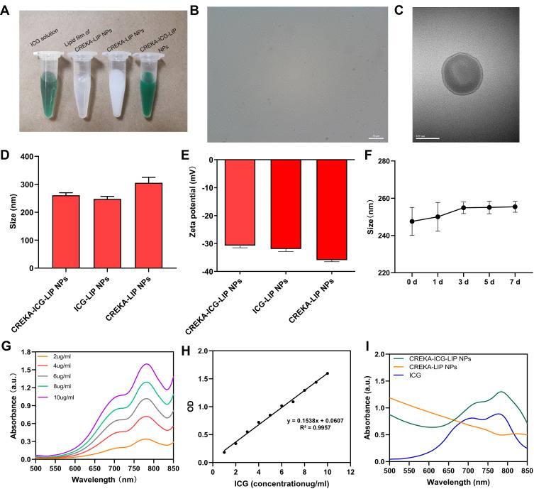
The CREKA-ICG-LIP NPs consisted of a shell/core structure and were prepared by one step method to encapsulate ICG into the lipid shell while simultaneously carrying CREKA on the surface. Figure 1A shows four solutions: a) the ICG solution; b) the lipid film of CREKA-LIP NPs in PBS; c) the CREKA-LIP NPs in PBS; and d) the CREKA-ICG-LIP NPs in PBS. In this picture, the lipid film of CREKA-LIP NPs in PBS is transparent white, the free ICG solution is green, the CREKA-LIP NPs solution is white, and the CREKA-ICG-LIP NPs solution is dark green because of the encapsulated ICG. Bright-field optical microscopy showed that the CREKA-ICG-LIP NPs featured a uniform size/shape morphology and high dispersity (Figure 1B). TEM of the microstructure of the CREKA-ICG-LIP NPs revealed that the CREKA-ICG-LIP NPs had a spherical morphology with a homogeneous distribution of ICG in the matrix (Figure 1C). The average size of the CREKA-ICG-LIP NPs, ICG-LIP NPs, and CREKA-LIP NPs was 260.77±9.00 nm (polydispersity index (PDI)=0.138), 247.60±9.18 nm (PDI=0.175), and 305.27±19.72 nm (PDI=0.134), respectively (Figure 1D). There was no statistical difference on average size between CREKA-ICG-LIP NPs and ICG-LIP NPs or CREKA-ICG-LIP NPs and CREKA-LIP NPs. The average zeta potential of the CREKA-ICG-LIP NPs, ICG-LIP NPs, and CREKA-LIP NPs was −30.50±0.78 mV, −31.93±0.91 mV, and −35.93±0.58 mV, respectively (Figure 1E). There was no significant difference in the mean diameter of the CREKA-ICG-LIP NPs at 0 d, 1 d, 3 d, 5 d, and 7 d (Figure 1F).
Figure 1.
Characterization of NPs. (A) Digital photos of ICG, the lipid film of CREKA-LIP NPs, CREKA-LIP NPs, and CREKA-ICG-LIP NPs solutions. (B) Optical microscopy image (scale bar = 10 um) and (C) TEM image (scale bar = 200 nm) of CREKA-ICG-LIP NPs. (D) Average size and (E) zeta potential of CREKA-ICG-LIP NPs, ICG-LIP NPs, and CREKA-LIP NPs. (F) Size of CREKA-ICG-LIP NPs at different time points (1 d, 3 d, 5 d, 7 d). (G) UV-vis-NIR spectra of ICG solution at different concentrations (2, 4, 6, 8, and 10 µg/mL). (H) Standard curve of ICG solution at 780 nm. (I) UV-vis-NIR spectra of ICG, CREKA-ICG-LIP NPs, and CREKA-LIP NPs.
Different free ICG solutions exhibited the same absorbance peak at 780 nm (Figure 1G). Compared with the CREKA-LIP NPs, the CREKA-ICG-LIP NPs had a characteristic absorption peak at 784 nm, which was similar to that of free ICG, indicating the successful loading of ICG into the CREKA-ICG-LIP NPs. In contrast, the CREKA-LIP NPs exhibited no such characteristic absorption peak (Figure 1I). To detect the EE of ICG, a standard curve (Figure 1H) based on the OD of different concentrations of ICG solutions at 780 nm was established. The EE of ICG in CREKA-ICG-LIP NPs was above 86.72%. The satisfactory EE of ICG demonstrates the potential capability of NPs for PA imaging.
Cytotoxicity and Safety Evaluation of NPs
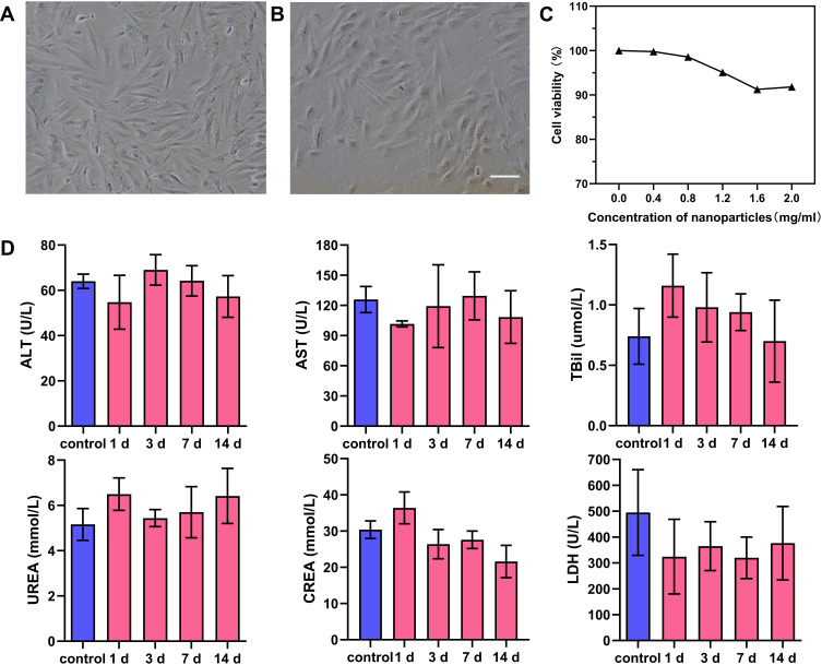
For further study, the systematic evaluation of NPs in vitro and in vivo is important. The cytotoxicity of CREKA-ICG-LIP NPs was investigated by CCK-8 assay in the dark. After 24 h of incubation, the results of the CCK-8 assay indicated that there was no obvious cytotoxicity to H9C2 cells in the arranged concentration range, and cell viability remained above 90%, even at a high concentration of up to 2 mg/mL (correspondingly, the concentration of ICG was 500 µg/mL), indicating the high biocompatibility of the NPs (Figure 2C). The morphology of the H9C2 cells at this concentration (Figure 2B) was not different from that of normal cells (Figure 2A).
Figure 2.
Cytotoxicity of NPs in vitro. (A) Normal morphology of H9C2 cell. (B) Cellular morphology after 24 h of incubation with CREKA-ICG-LIP NPs (2 mg/mL). Scale bar = 100um. (C) Cell viability of H9C2 cells treated with different concentrations of CREKA-ICG-LIP NPs (0.4, 0.8, 1.2, 1.6, 2.0 mg/mL). (D) Blood biochemical indexes in the control group (1 d, intravenous injection of PBS solution) and the experimental groups (1, 3, 7, 14 d, intravenous injection of CREKA-ICG-LIP NPs solution) (means ± s.d., n = 5).
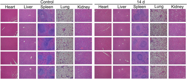
The in vivo safety evaluation was performed using rats intravenously administered CREKA-ICG-LIP NPs and examined at different times postinjection (1 d, 3 d, 7 d, and 14 d) compared to rats in the normal control group. The serum biochemistry profiles showed no statistically significant increase of biomarkers associated with liver function (ALT, AST, T-BiL), kidney function (UREA, CREA), cardiac function (LDH), or the routine blood test (RBC, WBC, PLT, HGB, MCV) compared with the control group (Figure 2D, S1), indicating undetectable toxicity in a short and relatively long period. HE staining of the major organs (heart, liver, spleen, lung, and kidney) at 1 d, 3 d, 7 d and 14 d postinjection showed no significant acute or chronic physiological toxicity such as cell damage, necrosis, or inflammatory reaction compared with the control group, indicating high histocompatibility (Figure 3).
Figure 3.
Safety evaluation of NPs in vivo. HE staining of major organs (heart, liver, spleen, lung, kidney) in the control group and the experimental group (14 d). Scale bar = 100um.
These results from in vitro and in vivo tests indicate that the CREKA-ICG-LIP NPs have suitable biocompatibility and histocompatibility for further in vivo study. This result can be attributed to the fact that lipids are endogenous components that are highly biocompatible, completely biodegradable, and nonimmunogenic for systemic and nonsystematic administration.32
Targeting Ability of NPs in vitro
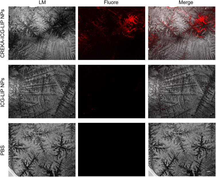
To determine the targeting ability of CREKA-ICG-LIP NPs, we prepared fibrin clots on microscope slides. As shown in Figure 4, the slides in the CREKA-ICG-LIP NPs group incubated with fibrin-targeted NPs showed obvious fluorescence signals on the surface of the fibrin clots, but no significant fluorescence was present in the control groups (ICG-LIP NPs and PBS groups), suggesting no fibrin-targeted binding ability for ICG-LIP NPs without CREKA. The results are consistent with those of other studies, which confirmed that CREKA has a great ability to bind fibrin.25,31
Figure 4.
Binding ability of NPs to fibrin clots in vitro. Fluorescence microscopy images of fibrin clots: white light image of fibrin clots (left), fluorescence image of NPs/DiI binding (middle), and merged white light and fluorescence images depicting clot binding (right). Scale bar=100um.
Targeting Ability and Distribution of NPs in vivo
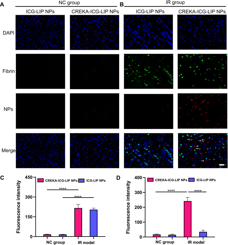
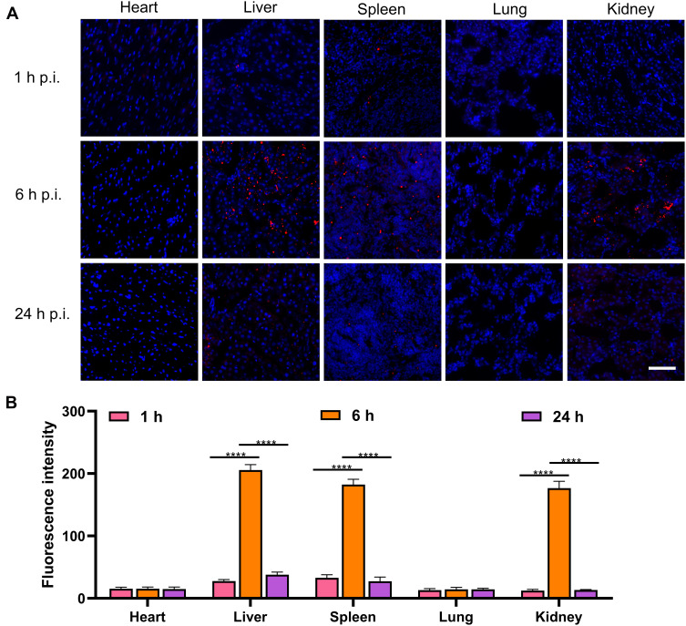
To prepared the successful animal model, we blockaded coronary blood circulation for 30 min. In the operation, we observed the color of the myocardium below the suture turned cyanosis or paling and ECG showed the characteristic elevation of the ST segment. After the operation, the IR model was further confirmed by TTC, HE and Masson staining of myocardium (Figure S2). To determine whether the CREKA-ICG-LIP NPs would be retained at the site of the myocardial injury in vivo, the targeting ability of the CREKA-ICG-LIP NPs was tested with rats with IR-induced injury. The rats were administered an intravenous injection of CREKA-ICG-LIP NPs solution or ICG-LIP NPs solution in NC group and IR group and followed by one hour of circulation time. In agreement with previous studies,22 fibrin (green) in the injured area of the heart in IR group was abundantly distributed but was rarely found in the normal myocardium in NC group (Figure 5A). The statistical results are consistent with this. The fibrin signal in IR group was significantly stronger than in NC group (Figure 5C). The red signal in the CREKA-ICG-LIP NPs group of IR group was significantly stronger than that in the CREKA-ICG-LIP NPs group of NC group and that in the ICG-LIP NPs group of IR group, which obviously colocalized with fibrin (Figure 5B and D). In NC group, there was no fluorescence from the NPs or fibrin in either the ICG-LIP NPs group or the CREKA-ICG-LIP NPs group. However, a weak red signal was also observed in the ICG-LIP NPs group of IR group because of enhanced vascular permeability. The fluorescence signal distribution in major organs (heart, liver, spleen, lung, kidney) 1 h, 6 h and 24 h after injection in normal rats was obtained. An obvious fluorescence signal (red) was observed in the liver, spleen, and kidney at 6 h and 24h after injection, weak fluorescence signal was observed in the liver, spleen at 1 h, and no fluorescence signal was observed in the heart and lung all the time (Figure 6A and B). This indicates that the NPs could be degraded by the liver-spleen system and kidney excretion.
Figure 5.
Targeting ability of NPs in vivo. (A) Fluorescence microscopy images of the heart in the NC group and (B) IR group after injection of CREKA-ICG-LIP/DiI NPs and ICG-LIP/DiI NPs. Blue fluorescence is attributable to cell nuclei. The arrow shows the colocalization of CREKA-ICG-LIP/DiI NPs (red) and fibrin(green). Scale bar = 20 µm. (C) Semi-quantitative analysis of partial fluorescence intensity of fibrin and (D) NPs. ****p<0.0001.
Figure 6.
Distribution of NPs in vivo. (A) Representative fluorescence images of the distribution in major organs 1 h, 6 h, 24 h postinjection (p.i.) of CREKA-ICG-LIP/DiI NPs. Blue fluorescence is attributable to cell nuclei. Red fluorescence is attributed to CREKA-ICG-LIP/DiI NPs. Scale bar=50 µm. (B) Quantified by partial immunofluorescence intensity of the major organ. ****p<0.0001.
PA Imaging Ability in vitro
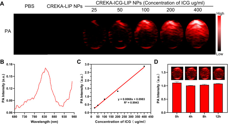
ICG has already been selected as a PA imaging agent in previous experiments because of its strong absorbance in the NIR region and great PA performance.28,33 In this study, ICG was used as a PA contrast agent and expected to show PA imaging ability when it was encapsulated in CREKA-ICG-LIP NPs. To determine its performance for PA imaging in vitro, we first determined the optical excitation wavelength. As presented in Figure 7B, 835 nm was determined to be the optical excitation wavelength for PA imaging after scanning from 680 nm to 970 nm. We prepared solutions of CREKA-ICG-LIP NPs at different concentrations with increasing ICG concentrations from 25 to 400 µg/mL to observe the changes of the PA signal in vitro at the optical excitation wavelength. CREKA-LIP NPs solution and PBS solution were used as controls. All PA images are shown in Figure 7A. The PA signal from the CREKA-ICG-LIP NPs solution was brighter than that from the CREKA-LIP NPs solution and PBS solution. Moreover, the PA signal intensity and the ICG concentration showed a positive linear correlation, indicating that the encapsulated ICG contributed to the PA imaging performance (Figure 7C).
Figure 7.
PA imaging of NPs in vitro. (A) PA images of PBS, CREKA-LIP NPs (2 mg/mL), CREKA-ICG-LIP NPs (25, 50, 100, 200, 400 µg/mL ICG). (B) PA spectrum of CREKA-ICG-LIP NPs (25 µg/mL ICG) from 680 nm to 970 nm. (C) In vitro PA signal intensity with increasing ICG concentration in CREKA-ICG-LIP NP solution. (D) PA images (insert images) and quantitative analysis of PA signal intensity of CREKA-ICG-LIP NPs solution (200 µg/mL ICG) over time.
Furthermore, to observe the stability of the PA signal, PA images of CREKA-ICG-LIP NPs (ICG 200 µg/mL) over time were obtained (Figure 7D). The PA signal intensity showed no obvious change, indicating the high stability of CREKA-ICG-LIP NPs for PA imaging performance. This result is different from that of ICG, which easily degrades due to its low photostability.28 CREKA-ICG-LIP NPs could encapsulate ICG in the NPs core to maintain its photostability for potentially continuous PA imaging.34,35
PA Imaging Ability in vivo
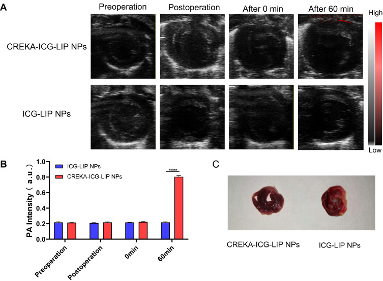
To investigate the PA imaging ability of CREKA-ICG-LIP NPs, rats with IR-induced injury were divided into two groups and administered CREKA-ICG-LIP NPs solution and ICG-LIP NPs solution to conduct PA imaging in vivo. According to the distribution range of the left anterior descending (LAD) coronary artery, we selected the short-axis interface to observe the PA signal of the heart area. A series of PA images of the heart was recorded (Figure 8A). First, no PA signal (red) from the heart was observed in any rat before or after the operation. Then, PA images immediately after injection showed no PA signal in either group. After one hour of blood circulation, no PA signal was found in the ICG-LIP NPs group. However, in contrast, a strong PA signal was observed in the anterior wall of the left ventricle in the CREKA-ICG-LIP NPs group. The location of the PA signal was consistent with the site of heart injury. The PA signal intensity in the ROI was further quantitatively analyzed by Vevo LAZR system software. The PA signal intensity was significantly higher in the CREKA-ICG-LIP NPs group than in the ICG-LIP NPs group (Figure 8B). After PA imaging, the TTC staining of the CREKA-ICG-LIP NPs group showed the injury region, which was consistent with the indication of PA images. (Figure 8C). These results showed that CREKA-ICG-LIP NPs can identify the infarct region by targeting an important ECM protein, fibrin. This technique relies on the abundant amount of fibrin deposited in the injury site because of the enhanced permeability and retention (EPR) effect during circulation and the high fibrin-targeting ability of CREKA. Based on the above findings, we provide a new direction to identify the injured region to facilitate the diagnosis of MI.
Figure 8.
PA imaging of NPs in vivo. (A) Merged US and PA images of the heart region. Images at different time points (preoperation, postoperation, 0 min after injection, 60 min after injection) after the injection of CREKA-ICG-LIP NPs solution and ICG-LIP NPs solution. (B) Corresponding quantitative analysis of the PA signal intensity values. ****p<0.0001. (C) TTC staining of myocardium in CREKA-ICG-LIP NPs group and ICG-LIP NPs group.
Conclusion
In summary, we successfully constructed fibrin-targeted CREKA-ICG-LIP NPs for PA imaging and proposed a noninvasive method to detect the infarct region and help diagnose MI. Using an endogenous component, ie, lipids, we loaded ICG into NPs for enhanced PA imaging stability and added CREKA to the surface of the NPs to target fibrin. Benefiting from the fibrin richly expressed at the injury site and the high binding affinity of CREKA to fibrin, the CREKA-ICG-LIP NPs displayed a great capability to target fibrin in the infarct region of heart. Due to the efficient encapsulation of ICG, the CREKA-ICG NPs exhibited enhanced PA imaging performance. Therefore, this work provides new insights for developing a fibrin-targeted PA agent to noninvasively image the infarct region in MI based on a PA imaging system with high sensitivity in optical imaging and deep penetration in US imaging. In parallel, a single detection modality is insufficient for diagnosis; multimodal imaging detection is necessary. Further research on NPs carrying genes or drugs for the integration of the diagnosis and treatment of MI is needed.
Acknowledgments
This work was financially supported by the National Natural Science Foundation of China (Grant Nos 82071926,81630047,31630026.).
Disclosure
The authors report no conflicts of interest in this work.
References
- 1.Lear SA, Hu W, Rangarajan S, et al. The effect of physical activity on mortality and cardiovascular disease in 130 000 people from 17 high-income, middle-income, and low-income countries: the PURE study. Lancet. 2017;390(10113):2643–2654. doi: 10.1016/S0140-6736(17)31634-3 [DOI] [PubMed] [Google Scholar]
- 2.Caldwell M, Martinez L, Foster JG, et al. Prospects for the primary prevention of myocardial infarction and stroke. J Cardiovasc Pharmacol Ther. 2019;24(3):207–214. doi: 10.1177/1074248418817344 [DOI] [PubMed] [Google Scholar]
- 3.Ito H. Myocardial contrast echocardiography after myocardial infarction. Curr Cardiol Rep. 2012;14(3):350–358. doi: 10.1007/s11886-012-0263-0 [DOI] [PubMed] [Google Scholar]
- 4.Döbert N, Britten M, Assmus B, et al. Transplantation of progenitor cells after reperfused acute myocardial infarction: evaluation of perfusion and myocardial viability with FDG-PET and thallium SPECT. Eur J Nucl Med Mol Imaging. 2004;31(8):1146–1151. doi: 10.1007/s00259-004-1490-4 [DOI] [PubMed] [Google Scholar]
- 5.Hidalgo A, Pons-Lladó G. Usefulness of cardiac MRI in the prognosis and follow-up of ischemic heart disease. Radiologia. 2015;57(3):201–212. doi: 10.1016/j.rx.2014.11.008 [DOI] [PubMed] [Google Scholar]
- 6.Stillman AE, Oudkerk M, Bluemke DA, et al. Imaging the myocardial ischemic cascade. Int J Cardiovasc Imaging. 2018;34(8):1249–1263. doi: 10.1007/s10554-018-1330-4 [DOI] [PubMed] [Google Scholar]
- 7.Ordovas KG, Higgins CB. Delayed contrast enhancement on MR images of myocardium: past, present, future. Radiology. 2011;261(2):358–374. doi: 10.1148/radiol.11091882 [DOI] [PubMed] [Google Scholar]
- 8.Zeng L, Ma G, Lin J, et al. Photoacoustic probes for molecular detection: recent advances and perspectives. Small. 2018;14(30):e1800782. doi: 10.1002/smll.201800782 [DOI] [PubMed] [Google Scholar]
- 9.Erfanzadeh M, Zhu Q. Photoacoustic imaging with low-cost sources: a review. Photoacoustics. 2019;14:1–11. doi: 10.1016/j.pacs.2019.01.004 [DOI] [PMC free article] [PubMed] [Google Scholar]
- 10.Steinberg I, Huland DM, Vermesh O, et al. Photoacoustic clinical imaging. Photoacoustics. 2019;14:77–98. doi: 10.1016/j.pacs.2019.05.001 [DOI] [PMC free article] [PubMed] [Google Scholar]
- 11.Manwar R, Hosseinzadeh M, Hariri A, et al. Photoacoustic signal enhancement: towards utilization of low energy laser diodes in real-time photoacoustic imaging. Sensors (Basel). 2018;18(10). [DOI] [PMC free article] [PubMed] [Google Scholar]
- 12.Attia ABE, Balasundaram G, Moothanchery M, et al. A review of clinical photoacoustic imaging: current and future trends. Photoacoustics. 2019;16:100144. doi: 10.1016/j.pacs.2019.100144 [DOI] [PMC free article] [PubMed] [Google Scholar]
- 13.Choi W, Park E-Y, Jeon S, et al. Clinical photoacoustic imaging platforms. Biomed Eng Lett. 2018;8(2):139–155. doi: 10.1007/s13534-018-0062-7 [DOI] [PMC free article] [PubMed] [Google Scholar]
- 14.Wilson K, Homan K, Emelianov S. Biomedical photoacoustics beyond thermal expansion using triggered nanodroplet vaporization for contrast-enhanced imaging. Nat Commun. 2012;3(1):618. doi: 10.1038/ncomms1627 [DOI] [PubMed] [Google Scholar]
- 15.Sano K. Development of molecular probes based on iron oxide nanoparticles for in vivo magnetic resonance/photoacoustic dual imaging of target molecules in tumors. Yakugaku Zasshi. 2017;137(1):55–60. doi: 10.1248/yakushi.16-00228 [DOI] [PubMed] [Google Scholar]
- 16.Upputuri PK, Pramanik M. Dynamic in vivo imaging of small animal brain using pulsed laser diode-based photoacoustic tomography system. J Biomed Opt. 2017;22(9):1–4. doi: 10.1117/1.JBO.22.9.090501 [DOI] [PubMed] [Google Scholar]
- 17.Beitzke D, Rasul S, Lassen ML, et al. Assessment of myocardial viability in ischemic heart disease by PET/MRI: comparison of left ventricular perfusion, hibernation, and scar burden. Acad Radiol. 2020;27(2):188–197. doi: 10.1016/j.acra.2019.03.021 [DOI] [PubMed] [Google Scholar]
- 18.Chen Q, Liang C, Sun X, et al. HO-responsive liposomal nanoprobe for photoacoustic inflammation imaging and tumor theranostics via in vivo chromogenic assay. Proc Natl Acad Sci U S A. 2017;114(21):5343–5348. doi: 10.1073/pnas.1701976114 [DOI] [PMC free article] [PubMed] [Google Scholar]
- 19.Frangogiannis NG. The extracellular matrix in myocardial injury, repair, and remodeling. J Clin Invest. 2017;127(5):1600–1612. doi: 10.1172/JCI87491 [DOI] [PMC free article] [PubMed] [Google Scholar]
- 20.Dobaczewski M, de Haan JJ, Frangogiannis NG. The extracellular matrix modulates fibroblast phenotype and function in the infarcted myocardium. J Cardiovasc Transl Res. 2012;5(6):837–847. doi: 10.1007/s12265-012-9406-3 [DOI] [PMC free article] [PubMed] [Google Scholar]
- 21.Dobaczewski M, Bujak M, Zymek P, et al. Extracellular matrix remodeling in canine and mouse myocardial infarcts. Cell Tissue Res. 2006;324(3):475–488. doi: 10.1007/s00441-005-0144-6 [DOI] [PubMed] [Google Scholar]
- 22.Huang Z, Song Y, Pang Z, et al. Targeted delivery of thymosin beta 4 to the injured myocardium using CREKA-conjugated nanoparticles. Int J Nanomedicine. 2017;12:3023–3036. doi: 10.2147/IJN.S131949 [DOI] [PMC free article] [PubMed] [Google Scholar]
- 23.Zanuy D, Curco D, Nussinov R, et al. Influence of the dye presence on the conformational preferences of CREKA, a tumor homing linear pentapeptide. Biopolymers. 2009;92(2):83–93. doi: 10.1002/bip.21122 [DOI] [PMC free article] [PubMed] [Google Scholar]
- 24.Wang LJ, Li HS, Wang QS, et al. Construction and evaluation of the tumor-targeting, cell-penetrating multifunctional molecular probe iCREKA. Contrast Media Mol Imaging. 2018;2018:7929617. doi: 10.1155/2018/7929617 [DOI] [PMC free article] [PubMed] [Google Scholar]
- 25.Zhao J, Zhang B, Shen S, et al. CREKA peptide-conjugated dendrimer nanoparticles for glioblastoma multiforme delivery. J Colloid Interface Sci. 2015;450:396–403. doi: 10.1016/j.jcis.2015.03.019 [DOI] [PubMed] [Google Scholar]
- 26.Poon C, Gallo J, Joo J, et al. Hybrid, metal oxide-peptide amphiphile micelles for molecular magnetic resonance imaging of atherosclerosis. J Nanobiotechnology. 2018;16(1):92. doi: 10.1186/s12951-018-0420-8 [DOI] [PMC free article] [PubMed] [Google Scholar]
- 27.Zhong Y, Zhang Y, Xu J, et al. Low-intensity focused ultrasound-responsive phase-transitional nanoparticles for thrombolysis without vascular damage: a synergistic nonpharmaceutical strategy. ACS Nano. 2019;13(3):3387–3403. doi: 10.1021/acsnano.8b09277 [DOI] [PubMed] [Google Scholar]
- 28.Chaudhary Z, Khan GM, Abeer MM, et al. Efficient photoacoustic imaging using indocyanine green (ICG) loaded functionalized mesoporous silica nanoparticles. Biomater Sci. 2019;7(12):5002–5015. doi: 10.1039/C9BM00822E [DOI] [PubMed] [Google Scholar]
- 29.Huang C, Zhang Z, Guo Q, et al. A dual-model imaging theragnostic system based on mesoporous silica nanoparticles for enhanced cancer phototherapy. Adv Healthcare Mater. 2019;8(19):e1900840. doi: 10.1002/adhm.201900840 [DOI] [PubMed] [Google Scholar]
- 30.Bi W, Jia J, Pang R, et al. Thyroid hormone postconditioning protects hearts from ischemia/reperfusion through reinforcing mitophagy. Biomed Pharmacother. 2019;118:109220. doi: 10.1016/j.biopha.2019.109220 [DOI] [PubMed] [Google Scholar]
- 31.Song Y, Huang Z, Xu J, et al. Multimodal SPION-CREKA peptide based agents for molecular imaging of microthrombus in a rat myocardial ischemia-reperfusion model. Biomaterials. 2014;35(9):2961–2970. doi: 10.1016/j.biomaterials.2013.12.038 [DOI] [PubMed] [Google Scholar]
- 32.Akbarzadeh A, Rezaei-Sadabady R, Davaran S, et al. Liposome: classification, preparation, and applications. Nanoscale Res Lett. 2013;8(1):102. doi: 10.1186/1556-276X-8-102 [DOI] [PMC free article] [PubMed] [Google Scholar]
- 33.Capozza M, Blasi F, Valbusa G, et al. Photoacoustic imaging of integrin-overexpressing tumors using a novel ICG-based contrast agent in mice. Photoacoustics. 2018;11:36–45. doi: 10.1016/j.pacs.2018.07.007 [DOI] [PMC free article] [PubMed] [Google Scholar]
- 34.Saxena V, Sadoqi M, Shao J. Enhanced photo-stability, thermal-stability and aqueous-stability of indocyanine green in polymeric nanoparticulate systems. J Photochem Photobiol B. 2004;74(1):29–38. doi: 10.1016/j.jphotobiol.2004.01.002 [DOI] [PubMed] [Google Scholar]
- 35.Han Y-H, Kankala RK, Wang S-B, et al. Leveraging engineering of indocyanine green-encapsulated polymeric nanocomposites for biomedical applications. Nanomaterials. 2018;8(6). [DOI] [PMC free article] [PubMed] [Google Scholar]


