Abstract
An innovative platform enabling complex discretization and manipulation of aqueous droplets is described. The system uses simple membrane displacement trap elements to perform multiple functions including droplet discretization, release, metering, capture, and merging. Multi-layer PDMS devices with membrane displacement trap arrays are used to discretize sample into nanoliter scale droplet volumes, and reliably manipulate individual droplets within the arrays. Performance is characterized for varying capillary number flows, membrane actuation pressures, trap and membrane geometries, and trapped droplet volumes, with operational domains established for each platform function. The novel approach to sample digitization and droplet manipulation is demonstrated through discretization of a dilute bacteria sample, metering of individual traps to generate droplets containing single bacteria, and merging of the resulting droplets to pair the selected bacteria within a single droplet.
Introduction
The use of microfluidic technology to discretize isolated sample volumes within individual droplets is an active area of research, with diverse applications in chemical and biological analysis and processing1 such as the production of microcapsules and microparticles,2,3 digital PCR,4 protein crystallization,5,6 and single-cell analysis.3 The discretization7 of sample into microscale volumes, typically ranging from picoliters to microliters, allows molecules, cells, particles, reagents, and analytes to be spatially constrained, providing unique benefits for their characterization, sorting and manipulation.8
One approach to sample discretization is based on the use of digital microfluidics,9 in which electrohydrodynamic techniques such as dielectrophoresis10,11 or electrowetting-on-dielectric (EWOD) are employed for droplet formation and manipulation.9 A key advantage of digital microfluidics lies in the ability to precisely control both droplet generation and manipulation, enabling on-demand splitting, metering, merging, and transport of discrete fluid volumes using electrical inputs. However, the fabrication of digital microfluidic devices is complicated by the need for integrated electrodes and high quality dielectric films, and the resulting devices generally require high voltage signals for droplet actuation. In contrast, discretization platforms based on droplet microfluidics employ hydrodynamic forces for droplet formation.7 While various microchannel droplet generator topologies have been demonstrated, they share a common approach in which a dispersed fluid phase is introduced into a continuous phase, with dispersed phase droplets forming at the junction through a combination of hydrodynamic and surface tension forces.
A variety of microfluidic approaches have been reported for the manipulation of discrete droplets, including generation, storage, retrieval, merging, and sorting.12–18 In each of these examples, a separate discretization step is required to form the initial sample droplets upstream of the storage and manipulation region, and thus requires the integration of a passive or active on-chip droplet generator to create an initial emulsion. After droplet formation, trapping is typically achieved by modifying the fluidic resistance of the trap using geometry. The lower resistance of the trap compared to main channel facilitates droplet trapping. While simultaneous removal of all trapped droplets may be achieved by flow reversal in the main channel,16 addressable and controlled removal of selected droplets has been demonstrated using mechanical valves15,17,18 or opto-thermal methods.10,19 Droplet removal using mechanical valves is an effective approach for precise control of droplet trapping and selective release without affecting the stability of other drops. While pneumatically-controlled microvalves can be scaled up easily, established droplet manipulation schemes using this approach employ relatively complex fabrication methods and require separate components for droplet generation and manipulation.18
In this paper, we present a robust method for forming and manipulating isolated sample volumes that enables controllable discretization, release, metering, transport, and capture of droplets within an array of individually addressable membrane displacement traps. The traps are simple elements consisting of an enclosed microwell with a single opening making a fluidic connection between the well and a microchannel for fluid delivery. An elastomer membrane is positioned to cover the microwell, such that when pressure is applied across the membrane it deflects into the trap, resulting in a reduction of trap volume and displacement of fluid from the trap into the connected microchannel. Implementation of the displacement traps is conceptually similar to conventional elastomer microvalves,20 but with the valve element serving as a displacement pump rather than a flow restriction component. By adjusting the applied membrane pressure, and thus the displacement, while simultaneously controlling the flow rate within the microchannel, different functions including droplet ejection, splitting, metering, and capture can be implemented. Unlike other systems developed for microdroplet manipulation, the platform employs a single actuation element for all functions. The system also eliminates the need for a separate droplet generation scheme by employing an active self-digitization method that enables selective discretization of droplets with differing content, and also supports the use of different initial droplet volumes based on the trap geometry. The simplicity and functionality of the technique make the membrane displacement traps well suited for applications demanding flexible control over large numbers of discrete fluid packets.
Materials and methods
Microfluidic device fabrication
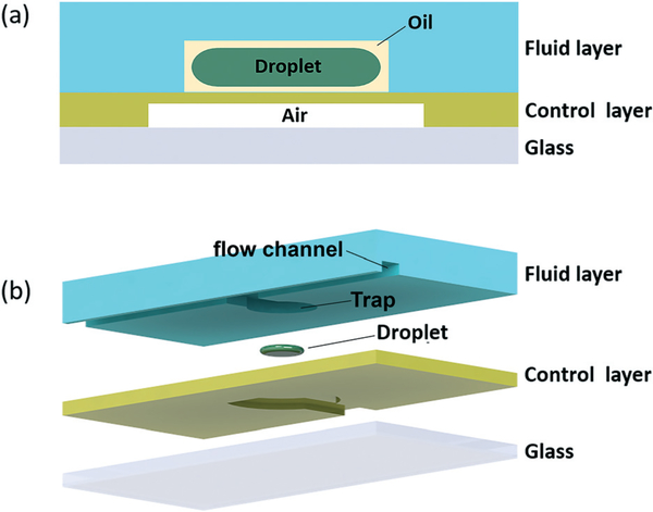
Membrane displacement trap chips were fabricated by conventional soft lithography using polydimethylsiloxane (PDMS) elastomer. Each displacement trap chip consists of an upper fluid layer containing microchannels and trap wells, a middle PDMS control layer for pneumatic actuation, and a lower glass substrate to provide a rigid support. A schematic of the push-up valve device21 is shown in Fig. 1. The upper fluid layer was molded from a photoresist master patterned from SU-8 2075 photoresist (Microchem, USA) fabricated by spin coating SU-8 on a silicon wafer at 3500 rpm for 60 s to obtain a film depth of 40 μm. To form the fluid layer, PDMS (10 : 1 base : curing agent) was poured onto the mold to a thickness of 3 mm and partially cured in an oven at 80 °C for 20 min. The tacky PDMS was removed from the mold, and inlet and outlet access holes were formed using a 500 μm diameter punch. The control layer mold was patterned by laminating a dry film photoresist (M115, Think and Tinker Ltd.) onto a silicon wafer to obtain a feature depth of 30 μm, and 20 : 1 PDMS was poured onto the mold and spin coated to a thickness of either 36 μm (1500 rpm) or 57 μm (1000 rpm) and partially cured at 80 °C for 11 min. Depending on the specific device design, dimensions of the main fluid channels in the PDMS layer ranged from 60–120 μm in width, with trap diameter equal to 200% of the main channel width, and trap neck opening equal to 150% of the channel width. Channels for the pneumatic control layer were 100 μm wide.
Fig. 1.
(a) Cross-sectional and (b) exploded views of a single membrane displacement trap element.
After both layers were partially cured, the flow layer was aligned and mated with the control layer under a microscope, and the resulting assembly was fully cured in an oven at 80 °C for 6–8 h. The assembly was then peeled off from the control layer mold wafer and access holes for pneumatic connections were formed using a 500 μm diameter punch. The devices were finally bonded to a glass slide following oxygen plasma treatment of the glass and exposed PDMS control layer surfaces for 45 s. Since the oxygen plasma treatment induces temporary hydrophilicity to the PDMS surface, the devices were incubated in an oven at 115 °C for 48 h (ref. 22) to restore the natural hydrophobic surface to the microchannels.
Typical membrane displacement trap chips included two independent inlet ports for the aqueous and oil phases and one outlet port for waste. For each design, the width of the main flow channel was matched to the radius of the trap. Droplet traps were present on either one or both sides of the main channel depending on device design. Each membrane was individually addressable by a separate pneumatic control line.
Experimental setup
To evaluate trap performance, green food colouring was dissolved in de-ionized water as the aqueous phase, and light mineral oil with 0.01% w/w Span 80 surfactant was used as the continuous oil phase. Two syringe pumps with glass syringes were used for each phase independently. For liquid introduction, the syringes were interfaced with the trap chips using flexible Tygon microbore tubing (0.51 mm ID, 1.52 mm OD, Cole-Parmer) connected to 22 gauge needle segments (Hamilton, USA) inserted in the fluidic access holes of the device. Elastomer membranes in the control layer were actuated using a solenoid valve manifold (Clippard, USA), interfaced with the microfluidic chip through urethane tubing (ID/OD – 0.06/0.13 inch, Clippard, USA) and 22 gauge needles inserted into on-chip pneumatic access holes. Input pressure was controlled through a gas regulator (9892K12, 5–50 psi range, McMaster-Carr) supplied with a high pressure nitrogen line, with regulator output connected to the valve manifold. The input pressure was held constant for each experiment. All experiments were monitored under an inverted microscope with an attached camera for image capture.
The manipulation of droplets containing bacteria were performed using WM11 E. coli which express enhanced green fluorescent protein (EGFP),23 allowing direct observation using an inverted fluorescence microscope (Nikon TE2000).
Results and discussion
Sample discretization
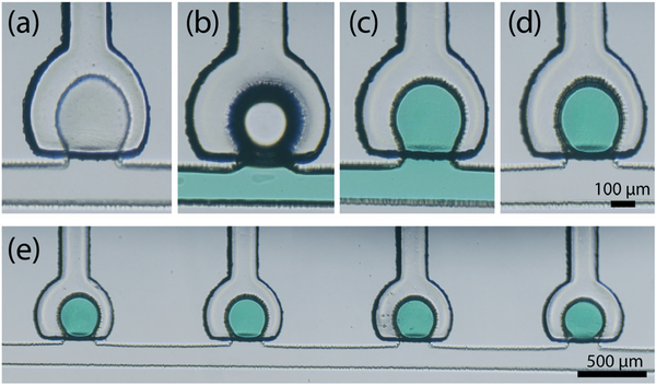
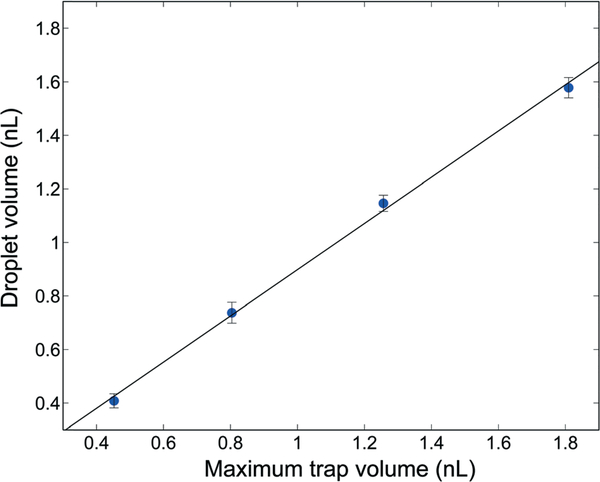
The active sample discretization process is depicted in Fig. 2. The process begins by first priming the entire fluidic network with oil. After oil filling, selected membranes are fully actuated to expel oil from the associated traps, followed by introduction of aqueous sample into the main channel. Once the channel is filled, the actuated membranes are released, enlarging the trap volumes and drawing aqueous fluid from the main channel into the selected traps. Finally, the channel is re-filled with oil at a flow rate between 0.1–0.5 μL min−1, displacing the aqueous phase from the main channel while leaving behind the discretized aqueous sample within the traps. Using a geometric droplet model to estimate the amount of trapped fluid, the discretized droplet volumes achieved using this process were found to be highly consistent, with relative standard deviations below 2%. The final droplet volume was found to scale linearly with the total trap volume, with the resulting droplets filling approximately 90% of the traps (Fig. 3).
Fig. 2.
Trap filling sequence for sample discretization. (a) A single trap element after oil priming, (b) introduction of aqueous phase into the system with the trap membrane actuated, (c) trap filling upon membrane release, and (d) final discretized droplet after oil backfill. (e) Reliable and uniform trapping is achieved across multiple trap array elements (Video S1†).
Fig. 3.
Estimated droplet volume scales linearly with the maximum available trap volume.
Droplet release
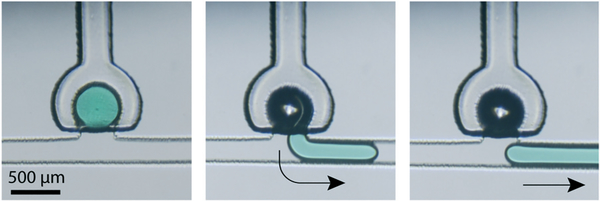
Following discretization, individual droplets may be selectively released by pressurizing the pneumatic control channel for a given trap. The resulting membrane deformation and associated reduction in trap volume ejects the selected droplet into the main channel, where flow of the continuous oil phase transports the droplet downstream, as shown in the sequence of images depicting a single droplet release event in Fig. 4.
Fig. 4.
Sequential images showing release of a 1.2 nL droplet with a main channel flow rate of 0.01 μL min−1 (Video S1†).
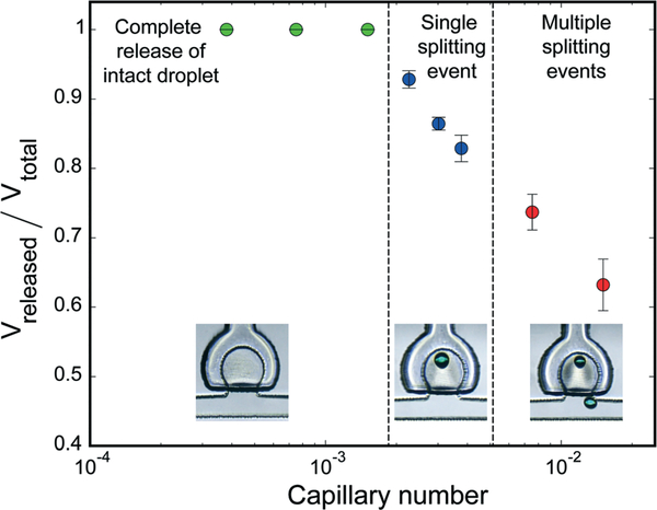
In an ideal droplet release event, the entire aqueous volume within the trap is ejected as a single intact droplet. Performance of the droplet release process is governed by the interplay of viscous or shear force due to oil flow and interfacial tension between aqueous and oil phase. This relationship can be expressed through the capillary number as Ca = Uμ/γ, where U is the linear velocity of oil, μ is the dynamic viscosity of oil and γ is the interfacial tension between oil and aqueous phase. To study the impact of the capillary number on droplet release, the oil flow rate within the main channel was varied using a device with an array of 200 μm diameter traps and a trap opening width of 150 μm, with trap membranes actuated at a pressure of 5 psi. Using values for the viscosity of oil22 and interfacial tension between oil and water24 given by μ = 30 cps and γ = 0.00829 kg cm−2, respectively, experiments show that highly repeatable and complete drop release occurs for low capillary numbers below Ca ~ 10−3, as shown in Fig. 5. At higher Ca values we observed single and then multiple splitting events during droplet release due to greater viscous forces acting on the droplets.
Fig. 5.
Effect of capillary number on droplet release performance. Droplet splitting occurs at higher Ca values due to increased viscous shear forces acting on the droplets during release. Example images of un-released volumes for each regime are shown inset.
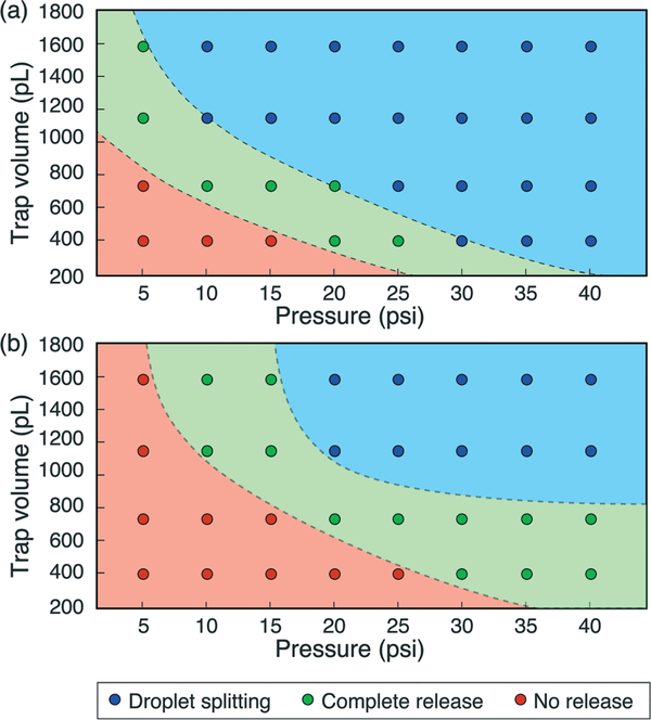
Within the low Ca regime, operational domains for effective droplet release were evaluated. These experiments were performed at a capillary number of Ca ~ 1.25 × 10⁻³ using trap elements with volumes ranging from 0.4 to 1.6 nL and actuator membrane thicknesses of either 36 μm or 57 μm, with the results presented in Fig. 6. Below a critical pressure, the membrane deflection is not sufficient to displace the droplet out of the trap, and no release is observed. Above this critical pressure, larger membrane deflection forces a sufficient portion of the trapped droplet into the main channel to allow the entire droplet to emerge intact. Droplet ejection is a dynamic process, with convective flow pulling the front of the droplet downstream while the remaining volume emerges from the trap under the influence of surface tension. Because the capillary number used in these experiments is below the critical value of Ca = 10−3, no splitting of the droplet is observed during release. Within this regime, intact droplet release is highly repeatable. As the actuation pressure is further increased, however, the sudden and large volume change within the trap disrupts the droplet’s water/oil interface, leading to uncontrolled droplet splitting during release.
Fig. 6.
Effect of pressure on droplet release for (a) 36 μm and (b) 57 μm membrane thickness when operating in the low capillary number regime, using traps with 100% coverage by the actuator membrane.
To better understand the relationship between actuation conditions and droplet release, the displaced membrane volume was estimated for each experiment using an analytic solution for deflection of a circular membrane given by,25,26
where w is the membrane deflection, P is the applied pressure, a is the membrane radius, r is the radial distance from the membrane center, and D is flexural stiffness of the membrane, defined as,
The stiffness expression includes material properties for the PDMS membrane, namely the elastic modulus (E) and Poisson’s ratio (ν). The mechanical properties of PDMS, which are dependent on fabrication parameters including the prepolymer ratio and curing temperature, were determined from the literature as E = 1.86 MPa and ν = 0.5.27 Integrating the deflection expression allows the displaced membrane volume to be determined. Based on this analytic evaluation, the transition between no release and intact release was estimated to occur for an average volumetric displacement of only 9% of the total trap volume for both membrane thicknesses, while the transition to the splitting regime was estimated at an average displacement of 24%.
Controlled droplet metering
In addition to enabling full release of selected droplets on demand, at low capillary numbers and moderate membrane pressures the membrane displacement traps allow portions of droplets to be precise metered into the main microchannel flow stream. As previously shown in Fig. 6, insufficient membrane actuation pressure results in no droplet release, while full droplet release occurs at higher pressures. However, the transition between these cases is gradual, and an intermediate regime exists where shear forces are able to controllably split the droplet as it emerges from the trap, metering a portion of the droplet into the flow channel.
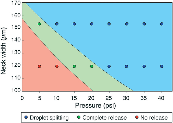
Control over droplet metering was found to be enhanced by reducing the portion of the trap covered by the actuator membrane, with optimal performance observed with the membrane covering ~75% of the trap length. The neck width of the trap also affected the operational domains by constraining the rate of droplet ejection into the main channel and reducing surface tension forces resisting shear during release (Fig. 7). Significantly, smaller neck widths result in higher hydrodynamic resistance against droplet ejection, reducing the likelihood of uncontrolled droplet splitting during release due to a sudden volume change in the trap. Improved metering may be possible by further optimizing these geometric parameters.
Fig. 7.
Effect of trap neck width on droplet release for 1.2 nL trap volume and 36 μm membrane thickness.
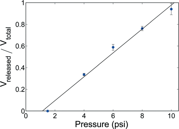
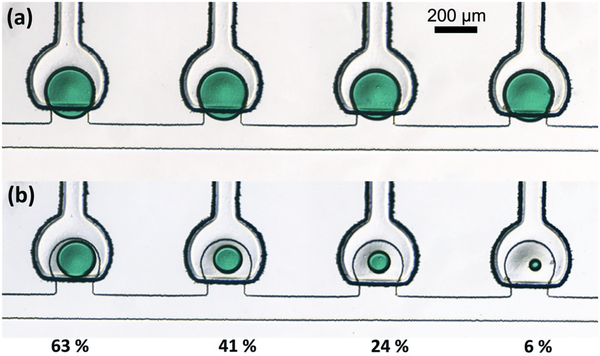
When using trap devices with 1.6 nL initial droplet volumes and 75% membrane coverage, the altered actuator alignment shifted the operational domains for release to somewhat lower pressures, with controlled drop shearing occurring at pressures below ~10 psi for channel flows with Ca < 10−3. The resulting relationship between membrane pressure and fractional metered droplet volume is presented in Fig. 8, and an example showing an array of droplets before and after controlled metering with different volumes remaining in each trap is shown in Fig. 9. Droplet metering has been reliably achieved with metered volumes ranging from 37% to 94% of the initial droplet volume, and repeatability of the metering process is excellent, with relative standard deviations below 3%.
Fig. 8.
Effect of pressure on drop splitting at Ca below 10−3 for a device with 36 μm membrane thickness, 1.6 nL initial droplet volume, and 75% membrane coverage (n = 4).
Fig. 9.
Controlled droplet metering at Ca < 10−3 for 1.6 nL trap volume and 36 μm membrane thickness. (a) Initial droplets and (b) droplets remaining after metering.
Droplet capture
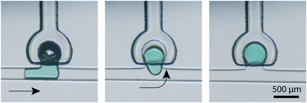
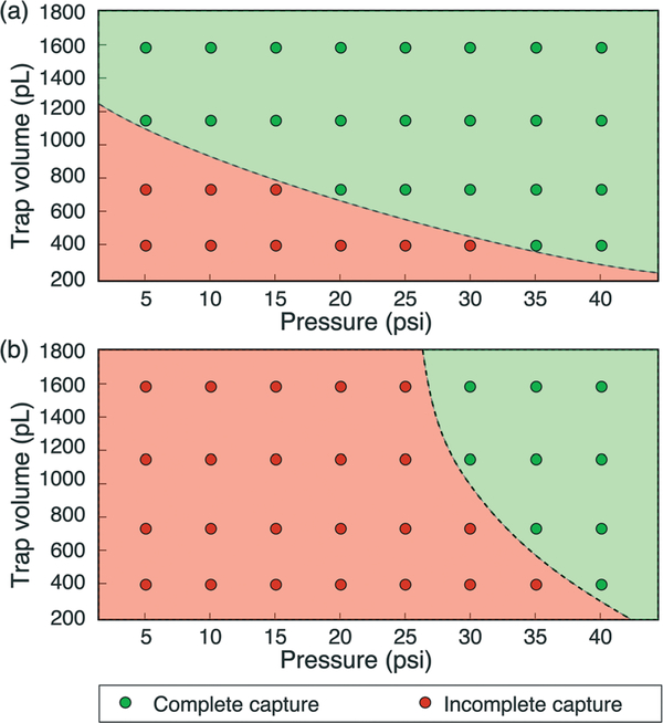
Following the ejection of a full or metered droplet into the main flow channel, the freed droplet may be re-captured by an empty downstream membrane displacement trap. Droplet capture is performed by actuating the empty trap membrane to reduce the trap volume, and releasing the membrane when the target droplet is adjacent to the trap opening. The active droplet capture process is depicted in Fig. 10, which shows the capture of a 1.2 nL droplet from an upstream trap. As expected, for a given trap volume, complete droplet capture occurs when applying a higher initial pressure to the membrane to increase the displaced volume (Fig. 11).
Fig. 10.
Sequential images showing capture of a 1.2 nL droplet with a main channel flow rate of 0.01 μL min−1 (Video S1†).
Fig. 11.
Effect of pressure on droplet capture for (a) 36 μm and (b) 57 μm membrane thickness.
In general, droplet capture was found to be highly repeatable for low Ca flows, with performance limited primarily by the ability to control actuator timing such that membrane pressure release coincides with positioning of the droplet in front of the trap entrance. Capture experiments were performed in this work by visually examining the droplets under a microscope and manually actuating the valves. The use of a vision system for automating droplet capture would further improve the reliability of the process.
Droplet merging
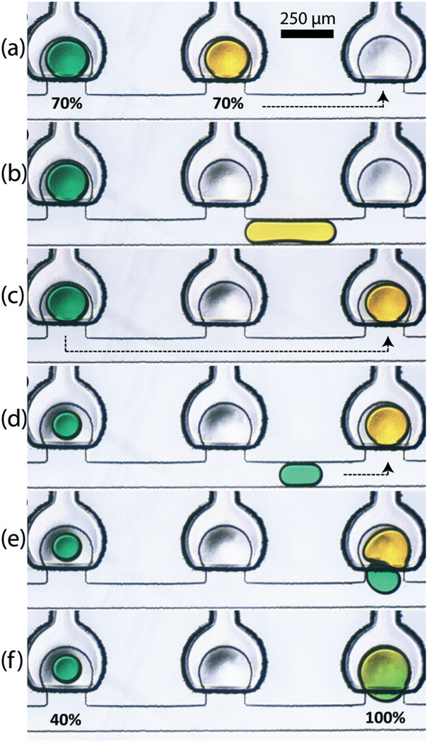
In addition to capturing individual droplets within an empty trap, the capture mechanism facilitates the merging of multiple droplets in a single trap. The merging of droplets containing two different dye solutions is shown in Fig. 12. Before initiating the merging process, portions of each droplet are metered to waste, leaving 70% of the droplet volumes within the traps. Next, the entirety of one droplet is ejected from its trap, and captured by the adjacent empty downstream trap where mixing will take place. A portion of the second droplet is then metered out and transported by convection to the mixing trap, where it is pulled in by release of the partially-actuated membrane. Once captured, the constrained droplets quickly merge into a single volume within the trap. Note that this example also demonstrates the capability of the displacement traps to be loaded with multiple solutions during the discretization process by simply performing sequential filling operations.
Fig. 12.
Merging sequence of two different samples where (a–c) release and re-capture of first sample (70%), (d) controlled splitting of second sample (30%) and (e and f) merging of 70% of sample 1 and 30% of sample 2 resulting in 100% of merged droplet (Video S2†).
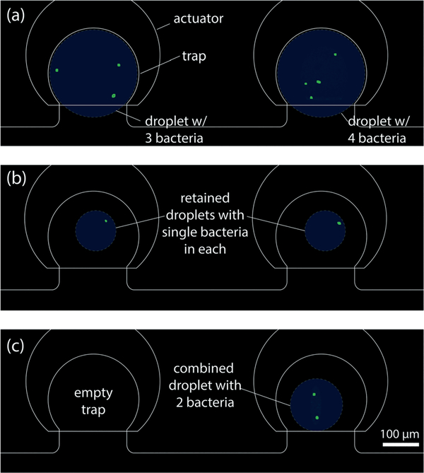
To explore the capabilities of the platform for the full set of functional steps including droplet formation, metering, capture, and merging, an experiment was performed with EGFP (enhanced green fluorescent protein)-expressing WM11 E. coli bacteria.23 Bacterial cells were first inoculated in standard LB (lysogeny broth) media supplemented with 50 μg mL−1 of ampicillin and kanamycin. These cells were incubated at 37 °C overnight until the cell number reached saturation, followed by a re-suspension step in PBS for dilution. This dilute solution of E. coli bacteria in PBS was discretized in a pair of traps, followed by repeated metering of small droplet volumes to waste until single bacteria were isolated within the remaining droplets (Fig. 13). This active approach to trapping individual particles differs from stochastic confinement, in which the particle concentration in the initial sample is selected to maximum the likelihood of single particle isolation during droplet formation,8,28,29 and offers the advantage of allowing a greater range of sample concentrations to be used. After discretizing bacteria droplets (Fig. 13a) and isolating individual bacteria (Fig. 13b), one droplet was fully ejected from its trap and captured by the second downstream trap, thereby merging the pair of bacteria into a single droplet (Fig. 13c). This process demonstrates the ability to achieve precise control over the final droplet content, and suggests that the platform may offer value for studies involving communities of bacteria with populations controlled at the single cell level.
Fig. 13.
Merging sequence of bacteria (a) three bacteria in first trap and four bacteria in the second trap, (b) single bacterium in both the traps after controlled splitting of original drop volume and (c) droplet release from first trap and merged into the second trap resulting in a single droplet with two bacteria.
In the above work, surfactant (Span 80) was used to facilitate droplet discretization and manipulation. When no surfactant was present, inconsistent discretization was observed due to high interfacial surface tension. Under this condition, the aqueous phase was difficult to fully remove from the main channel to form isolated water droplets in each trap, and often resulted in larger drop volumes with some portion of the droplet remaining in the trap neck. In contrast, at significantly higher surfactant concentrations beyond the 0.01% level used here, smaller droplets would be expected, with a greater chance for drop splitting during ejection and more controllable droplet metering due to the lower interfacial tension.
Conclusion
The membrane displacement traps provide a simple yet robust and highly functional solution for applications demanding digitization of sample into discrete droplets, and advanced unit operations for manipulating the resulting sample packets. The platform provides flexible and programmable control over droplet manipulation, using a single actuator topology to perform all key droplet operations including discretization, release, transport, capture, metering, and merging. Higher levels of integration, for example through the addition of membrane valves in the main flow channel to enable bidirectional transport of droplets within a trap array, may be readily envisioned to further enhance the utility of the technology. Additionally, scaling of the platform to larger arrays of trap elements can be achieved using a pneumatic multiplexer,30,31 allowing 2n traps to be actuated with only 2n off-chip pneumatic valves. The platform described here offers a new approach for integrating capabilities for diverse chemical and biological processes such as control and analysis of multistep (bio)chemical reactions, single-cell pairing experiments, multiplexed diagnostics, cell-free protein synthesis, and synthetic biology.
Supplementary Material
Acknowledgements
This research work was supported by the National Science Foundation through grants ECCS1609074 and CMMI1562468, and by funding from the Intramural Research Program of the National Institutes of Health (NIH), National Cancer Institute, Center for Cancer Research through a CCR FLEX Award. We thank Ryan McKay, Imaly Nanayakkara, and the Bentley laboratory in the Department of Bioengineering at the University of Maryland for providing the WM11 E. coli bacteria used in this work.
Footnotes
Conflicts of interest
There are no conflicts to declare.
Electronic supplementary information (ESI) available. See DOI: 10.1039/c7lc00910k
References
- 1.Shang L, Cheng Y and Zhao Y, Chem. Rev, 2017, 117, 7964–8040. [DOI] [PubMed] [Google Scholar]
- 2.Chou WL, et al. , Micromachines, 2015, 6, 1249–1271. [Google Scholar]
- 3.Shembekar N, Chaipan C, Utharala R and Merten CA, Lab Chip, 2016, 16, 1314–1331. [DOI] [PubMed] [Google Scholar]
- 4.Ahrberg CD, Manz A and Chung BG, Lab Chip, 2016, 16, 3866–3884. [DOI] [PubMed] [Google Scholar]
- 5.Leng J and Salmon J-B, Lab Chip, 2009, 9, 24–34. [DOI] [PubMed] [Google Scholar]
- 6.Li L and Ismagilov RF, Annu. Rev. Biophys, 2010, 39, 139–158. [DOI] [PubMed] [Google Scholar]
- 7.Zhu P and Wang L, Lab Chip, 2017, 17, 34–75. [DOI] [PubMed] [Google Scholar]
- 8.Collins DJ, et al. , Lab Chip, 2015, 3439–3459. [DOI] [PubMed] [Google Scholar]
- 9.He J-L, Chen A-T, Lee J-H and Fan S-K, Int. J. Mol. Sci, 2015, 16, 22319–22332. [DOI] [PMC free article] [PubMed] [Google Scholar]
- 10.Pit AM, Duits MHG and Mugele F, Micromachines, 2015, 6, 1768–1793. [Google Scholar]
- 11.Cetin B and Li D, Electrophoresis, 2011, 32, 2410–2427. [DOI] [PubMed] [Google Scholar]
- 12.Xi H-D, et al. , Lab Chip, 2017, 17, 751–771. [DOI] [PubMed] [Google Scholar]
- 13.Chong ZZ, et al. , Lab Chip, 2016, 16, 35–58. [DOI] [PubMed] [Google Scholar]
- 14.Wang W, Yang C and Li CM, Lab Chip, 2009, 9, 1504–1506. [DOI] [PubMed] [Google Scholar]
- 15.Simon MG, Lin R, Fisher JS and Lee AP, Biomicrofluidics, 2012, 6, 1–13. [DOI] [PMC free article] [PubMed] [Google Scholar]
- 16.Huebner A, et al. , Lab Chip, 2009, 9, 692–698. [DOI] [PubMed] [Google Scholar]
- 17.Jin SH, et al. , Lab Chip, 2015, 15, 3677–3686. [DOI] [PubMed] [Google Scholar]
- 18.Jeong H-H, et al. , Lab Chip, 2016, 16, 1698–1707. [DOI] [PubMed] [Google Scholar]
- 19.Fradet E, et al. , Lab Chip, 2011, 11, 4228–4234. [DOI] [PubMed] [Google Scholar]
- 20.Marc SR, Unger A, Chou H-P, Thorsen T and Scherer A, Science, 2000, 288, 113–116. [DOI] [PubMed] [Google Scholar]
- 21.Studer V, et al. , J. Appl. Phys, 2004, 95, 393–398. [Google Scholar]
- 22.Cohen DE, Schneider T, Wang M and Chiu DT, Anal. Chem, 2010, 82, 5707–5717. [DOI] [PMC free article] [PubMed] [Google Scholar]
- 23.McKay R, et al. , Biotechnol. Bioeng, 2017, DOI: 10.1002/bit.26391. [DOI] [Google Scholar]
- 24.Zhou H, et al. , Appl. Phys. Lett, 2013, 103, 234102. [Google Scholar]
- 25.Timoshenko S and Woinoskly-Krieger S, Theory of Plates and Shells, McGraw-Hill, 1959. [Google Scholar]
- 26.Bitsie F, Eaton WP, Plummer DW and Smith JH, in Proc. Int. Conf. Modeling and Simulation of Microsystems, San Juan, Puerto Rico, 1999, pp. 640–643. [Google Scholar]
- 27.Johnston ID, McCluskey DK, Tan CKL and Tracey MC, J. Micromech. Microeng, 2014, 24, 35017. [Google Scholar]
- 28.Köster S, et al. , Lab Chip, 2008, 8, 1110–1115. [DOI] [PubMed] [Google Scholar]
- 29.Mazutis L, et al. , Nat. Protoc, 2013, 8, 870–891. [DOI] [PMC free article] [PubMed] [Google Scholar]
- 30.Kawai K, Arima K, Morita M and Shoji S, J. Micromech. Microeng, 2015, 25, 65016. [Google Scholar]
- 31.Thorsen T, Maerkl SJ and Quake SR, Science, 2002, 298, 580–584. [DOI] [PubMed] [Google Scholar]
Associated Data
This section collects any data citations, data availability statements, or supplementary materials included in this article.


