Abstract
In this work, multi-scale finite element analyses based on three-dimensional (3D) hybrid macro/micro-scale computational models subjected to various loading conditions are carried out to examine the in-situ effect imposed by the neighboring plies on the failure initiation and propagation of cross-ply laminates. A detailed comparative study on crack suppression mechanisms due to the effect of embedded laminar thickness and adjacent ply orientation is presented. Furthermore, we compare the results of in-situ transverse failure strain and strength between the computational models and analytical predictions. Good agreements are generally observed, indicating the constructed computational models are highly accurate to quantify the in-situ effect. Subsequently, empirical formulas for calculating the in-situ strengths as a function of embedded ply thickness and different ply angle between embedded and adjacent plies are developed, during which several material parameters are obtained using a reverse fitting method. Finally, a new set of failure criteria for σ22-τ12, σ22-τ23, and σ11-τ12 accounting for the in-situ strengths are proposed to predict laminated composites failure under multi-axial stress states. This study demonstrates an effective and efficient computational technique towards the accurate prediction of the failure behaviors and strengths of cross-ply laminates by including the in-situ effects.
Keywords: In-situ effect, Hybrid macro/micro-scale computational model, Failure criteria, Cross-ply laminates
1. Introduction
The accuracy of strength prediction of composites is a longstanding challenge and it largely relies on the ability of adopted failure criteria to capture damage onset associated with a given failure mechanism. When the ply is embedded in a multidirectional laminate, phenomenological failure criteria [1] are usually expressed in terms of the in-situ strengths. The in-situ effect refers to the fact that the strengths of a single laminar embedded in multi-directional laminates are usually higher than those of unidirectional (UD) laminates obtained by classic material tests, due to that the crack initiation and propagation in a single laminar are delayed by adjacent plies depending on geometrical factors such as ply thickness or ply angles [2, 3].
Experimental studies have shown that the lay-up of laminated composites significantly affects failure modes and ultimate strength. For cross-ply laminates loaded in uniaxial tension, Parvizi et al. [2] showed that the transverse tensile strength of a UD ply constrained by plies of different fiber orientations, i.e. ply angles, is greater than the strength of the pure UD composites, and further that the transverse tensile strength depends on the thickness of the embedded ply. The experiments on cross-ply and angle-ply laminates showed that the failure stress or strain at the onset of the transverse cracks in layer under transverse tension is a function of n and θ of the laminates [4]. It should be noted that, while there is no direct experimental evidence of the in-situ effect for transverse compression, some recent tests containing structural details indicate that the ply thickness indeed affects the compressive strengths [5–7]. Also, the experimental results indicated that the ply thickness and laminate lay-up have a strong effect on the failure of multidirectional laminates subjected to combined tension/compression and shear loading[8]. However, the unloading process [9] and improper handling of the specimen during experiments for studying the in-situ effect in laminated composites could cause some additional damage to the instantaneous state of the specimen, which might lead to unrealistic characterizations on the in-situ effect. Moreover, experimental data are scarce since the measurement techniques used in the past are time consuming and involve a lot of specimen handling during testing.
To overcome the hurdles encountered in experiments, computational simulations using multi-scale hybrid models [10–19] have become an effective method to investigate the in-situ effect [20–26]. Saito et al. [20] computationally investigated the mechanisms of damage suppression, matrix cracking in a thin-ply laminate. They found that the crack propagation behavior in the mid-90° layer was significantly influenced by the change in the thickness of embedded plies. Arteiro et al. [21, 22] performed micromechanical analysis into the in-situ effects in polymer composite laminates and mechanical response of thin plies under transverse tensile and compressive loading. Transverse crack suppression effect and the consequent increase of the in-situ transverse tensile and compressive strength were clearly observed in very thin plies. Reinoso et al. [27] used two different approaches including fracture mechanics and phase-field modeling to predict the strength of thin ply laminates, which provide reliable qualitative and quantitative comparisons with experimental data, confirming the accuracy and applicability of the computational method to simulate fracture events in thin ply laminates at industrial level. Parvizi et al. [2] studied the influence of the ply thickness on the strain-to-failure of the 90° layers on glass-epoxy cross-ply [0/90]s laminates by varying the relative thickness of the inner 90° layers with respect to the supporting 0° plies. They found that thinner internal layers have higher critical strain for crack initiation and crack density. However, one main shortcoming of the aforementioned studies is that they tend to neglect the effect of stiffness of the neighboring outer plies, which is highly dependent on ply angles.
In addition to experimental and computational works mentioned above, analytical models to predict the in-situ transverse tensile strengths and in-plane shear strength were firstly proposed by Camanho et al. [3] for thick and thin plies. Later, it was also shown that the in-situ transverse compressive strength , and out-of-plane shear strength can be estimated based on [1, 28]. All these models have been intensively used, and the ability to correctly estimate the in-situ strengths have been proved for conventional [0/90/0] cross-ply laminates [22, 29]. Furthermore, an analytical model has been developed by Larry et al. [30] to describe the effect of load distribution on the fiber buckling strength of UD composites and determine the in-situ fiber buckling strength of notched composites under longitudinal compression loading, which was determined to be 1.78 times higher than the intrinsic fiber buckling strength (XC) [30]. Afterwards, the calculated in-situ strengths from analytical models were incorporated with the failure criteria to predict failure behaviors of laminated composite structures. However, it should be noted that aforementioned analytical models for predicting in-situ strengths , , , , and also neglect the effect of the laminates’ lay-up or the stiffness of the neighboring outer plies that constrain the embedded ply. Despite of the progress, general theoretical formulations for reliable and accurate in-situ strength predictions with full consideration of the constraining effect of adjacent plies and the embedded laminar thickness are still urgently demanded.
The objective of this work is to systematically study the in-situ effect in cross-ply laminates under transverse tension, transverse compression, in-plane/out-of-plane shear, and longitudinal compression by considering both the embedded ply thickness and stiffness of adjacent ply. We utilize 3D hybrid macro/micro-scale models consisting of a detailed micromechanics RVE model between two homogenized outer plies represented by macroscopic models. Subsequently, comparisons between the results of in-situ transverse tensile failure strain , strength , and in-situ transverse compressive strength obtained from computational models and analytical models are presented to validate our modeling strategy. In addition, we propose empirical formulas for calculating the in-situ strengths , , , , and as a function of mid-90° ply thickness b and different ply angle Δθd between mid-ply and adjacent ply, during which several material parameters are obtained using a reverse fitting method. Finally, the in-situ strengths , , , , and incorporating the in-situ effects are leveraged to develop a set of RVE-based failure criteria for σ22-τ12, σ22-τ23, and σ11-τ12, which are capable of predicting laminated composites failure under multi-axial stress states.
2. Constitutive modeling for the cross-ply laminates
2.1. Micromechanics RVE model used for mid-plies
In the micromechanics RVE model, we differentiate three phases, which are carbon fiber, the interphase region, and the resin matrix. We also use zero-thickness cohesive elements to represent the interface between fiber and the interphase region. The same configuration has been used in our previous studies [10, 11]. Carbon fibers are assumed to be transversally isotropic and linearly elastic. The five independent material constants of AKSACA carbon fibers are provided by the Dow Chemical Company, as listed in Table 1. The average fiber diameter is 7 μm, which gives rise to a fiber volume fraction of 51.4%. The matrix adopted in this study is developed by the Dow Chemical company. Uniaxial tensile, compressive, and Mode I fracture toughness tests are conducted according to ASTM D638 [31], ASTM D695 [32], and ASTM E399 [33], respectively. Table 1 summarizes the basic epoxy properties obtained through experiments, where Em is Young’s modulus; vm is Poisson’s ratio in the elastic region; vp refers to the Poisson’s ratio in the plastic region; σft is tensile strength; σfc is compressive strength; and GIC represents the Mode I fracture toughness. The matrix of epoxy is modeled as isotropic elasto-plastic and it follows isotropic damage law proposed by Melro et al. [34], implemented as an VUMAT user subroutine of the FE commercial software Abaqus [35]. A paraboloidal yield criterion, defined as a function of the stress tensor and the compressive and tensile yield strength, is used together with a non-associative flow rule, which allows for an accurate description of the volumetric deformation in plastic regime. Damage onset is defined by a damage activation function similar to the paraboloidal yield criterion but with actual compressive and tensile strengths of the epoxy matrix instead.
Table 1.
Properties of the cross-ply laminates used in the micro-model
| Carbon fiber | E11(GPa) | E22=E33 (GPa) | G12=G13 (GPa) | G23 (GPa) | v12 |
| 245 | 19.8 | 29.19 | 5.92 | 0.28 |
| Epoxy matrix | Em (GPa) | vm | vp | σft (MPa) | σfc (MPa) | GIc (J/m2) |
| 3.73±0.30 | 0.38±0.01 | 0.3 | 61.6±4.6 | 300±30.6 | 334.1±73 |
| Interphase region | Ei (GPa) | σi (MPa) |
| 22.5 | 670 |
| Interface | K (MPa/mm) | σ1 (MPa) | σ2, σ3 (MPa) | GIc (J/m2) | GIIc, GIIIc (J/m2) |
| 108 | 70 | 80 | 2 | 32 |
A submicron-thick interphase region exists between carbon fibers and the matrix. It has been demonstrated that the interphase property has a significant influence on the composite mechanical performance [11, 36, 37]. The properties of the interphase region have been calibrated based on molecular dynamics simulations and an analytical gradient model as shown in our previous studies [11]. The constitutive behavior and damage model of the interphase are assumed to be similar to those of the resin matrix proposed earlier [11]. In addition, the interphase region includes the nanoconfinement effect by the carbon fiber surface and the incompatibility between sizing and resin. The average mechanical properties have been estimated to be higher than those of resin matrix, as listed in Table 1. Our previous study shows that the accuracy of the modified RVE model including the interphase region is improved significantly [11], corroborating that the interphase region is stiffened on average and the existence of finite thickness interphase around carbon fibers increases the loading bearing capability of the composites. The interface between fiber and interphase region is modeled using zero thickness cohesive elements with the constitutive response defined by a bilinear mixed-mode softening law in Abaqus [35]. Damage onset is predicted by a quadratic interaction criterion that depends on interface strength for each of the damage modes. Once debonding is initiated, the cohesive tractions linearly decrease to zero. We also adopt the energy-based Benzeggath-Kenane (BK) damage propagation criterion to account for the dependence of the fracture energy dissipation on fracture modes [38]. A coupled experimental-computational micromechanics approach is adopted to calibrate and validate the cohesive parameters of the interface, as shown in our previous studies [11]. The cohesive parameters are also listed in Table 1. This computational micromechanics model has been used to study the mechanical properties and failure behaviors of composites [39], and it has shown great accuracy in predicting failure strength and failure mechanisms of the composite [10, 11].
2.2. Macroscopic models for outer plies
The outer plies are modeled as a homogenized continuum with a linear-elastic transversely isotropic material behavior. Since they are introduced to assess the constraining effect of the adjacent plies on the mechanical response and damage evolution of the plies of interest, neither nonlinear nor fracture behaviors are considered. Our purpose is to use the homogenized ply model to represent the macroscopic elastic behavior of the surrounding lamina. The relevant material properties of homogenized outer plies are given in Table 2. Similarly to the fiber-interphase region interface, the interface between adjacent plies is modeled using the cohesive elements, of which the mechanical behavior is represented by a bilinear traction-separation law depending on the displacement jump across the interface. The parameters of the traction-separation law have been determined in our previous study [12]. In particular, the fracture toughness of the interface was obtained by a width-tapered double cantilever beam for Mode-I and an edge notched flexure specimen for Mode-II, and the interfacial strengths are calculated based on the load-displacement curves. The properties of the interface between adjacent plies are also listed in Table 2.
Table 2.
Properties of the homogenized plies and interface between adjacent plies used in the macro-model
| Homogenized outer plies | E11 (GPa) | E22=E33(GPa) | G12=G13(GPa) | G23 (GPa) | v12 | |
| 127.5±2.7 | 9.2±4.5 | 4.86±1.7 | 2.74±2.4 | 0.33±0.01 | ||
| XT (MPa) | XC (MPa) | YT (MPa) | YC (MPa) | SL (MPa) | ST (MPa) | |
| 2022.4±35 | 1098.74±22 | 62.75±3.7 | 185.9±25 | 81.59±11 | 60.7±5.8 | |
| Interface between adjacent plies | K (MPa/mm) | σ1 (MPa) | σ2, σ3 (MPa) | GIc (J/m2) | GIIc(J/m2) | |
| 105 | 17 | 60 | 550±90 | 913±120 | ||
3. Hybrid micro-macro computational model of the cross-ply laminates
3.1. Cross-ply laminates under transverse tensile load
Numerous studies have shown that pure 90° laminar develops transverse cracks under considerably lower transverse tensile strain than that in the mid-90° ply of [0/90/0] cross-ply laminates. Studies have also suggested that the applied strain at which transverse cracks penetrate through the thickness of mid-90° ply tends to increase with decreasing mid-90° ply thickness [40, 41] or increasing extensional stiffness of the neighboring plies. Here, we first experimentally confirm the crack suppression effect imposed by the neighboring plies by comparing pure 90° UD CFRP composites and [0/90/0] cross-ply laminates. The results show that once a transverse crack is developed in pure 90° UD CFRP composites, it rapidly localizes and penetrates through the thickness, as shown in Fig. 1(a). However, for a [0/90/0] cross-ply laminate, the drastic transverse crack extension is significantly suppressed by the neighboring 0° plies, which leads to additional development of new transverse cracks in [0/90/0] cross-ply laminates, as shown in Fig. 1(b).
Figure 1.
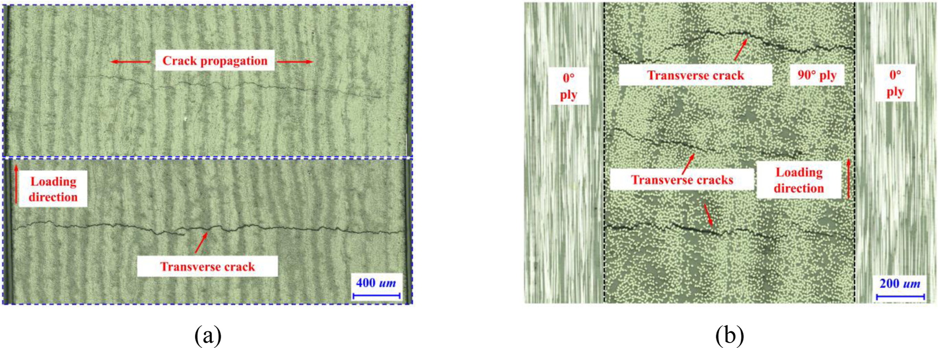
Photographs of transverse crack growth in the (a) pure 90° UD CFRP composites and (b) [0/90/0] cross-ply laminates.
In order to effectively study the constraint effect, i.e., in-situ effect, imposed by the neighboring plies on the mechanical response of cross-ply laminates under transverse tensile load, 3D hybrid micro-macro computational models for laminated composites with a layup of [θ/90/θ] consisting of a micro-RVE of 90° lamina in-between two homogenized θ-orientation plies are proposed. As presented in Fig. 2, the mid-90° RVE length L is 60R (0.21 mm), which is long enough to capture sufficient transverse crack density [21]. t is the thickness of each individual outer ply, and also equal to 60R throughout the analysis. The thickness of 3D computational models (parallel to fiber direction) is R (0.0035 mm). Transverse crack evolution in the mid-90° ply and the specific in-situ effect when subject to tension loading along X-direction will be studied in this section. The thickness of the mid-ply RVE model b ranges from 0.025 mm to 0.225 mm and the orientation of the outer plies θ varies from 0° to 60°. In addition, theoretical analysis on the dependence of in-situ strengths of the mid-ply on these variables will be carried out and compared with computational results.
Figure 2.
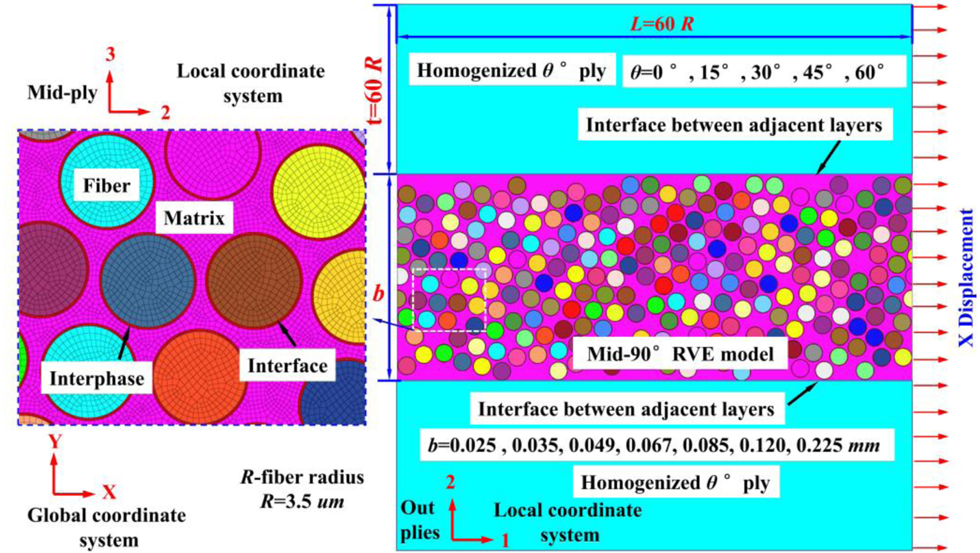
Schematic diagram of the hybrid micro-macro model for laminated composites with a layup of [θ/90/θ] under X-direction tension.
An orphan mesh technique with predominantly first-order hexahedral elements under reduced integration (C3D8R) and tetrahedral elements (C3D6) are adopted for fiber, matrix, and the interphase region. First-order cohesive elements (COH3D8) are used to represent the interface and C3D8R are used for homogenized outer plies. To generate a well-structured, high-quality mesh, a seed density of about 2 elements in the thickness of the interphase region is used, leading to an average element size for the interphase region of 0.1 um. The element size of fiber/matrix and homogenized outer plies are 0.15 um and 0.5 um, respectively. The applied boundary conditions play a key role in the predictions of the homogenized properties. The classical boundary conditions in the RVE model are periodic boundary conditions (PBCs), by means of the definition of strong relations (equations) between periodic nodes [42]. Since the application of the PBCs in the hybrid micro-macro model increases the complexity of numerical simulations, especially when non-linearity is involved in the simulations, we apply uniform boundary conditions (displacement) in this study. It has been shown that for sufficiently large models, the results obtained from using PBCs are close to those from using uniform boundary conditions [43].
3.1.1. The effect of embedded ply thickness b
In this section, the orientation of the outer plies θ is set to be 0° and we focus on the influence of embedded ply thickness b on the onset and propagation of transverse cracks within itself of [0/90/0] cross-ply laminates. For a thin mid-90° ply with b=0.025 mm, at relatively small strain ε=0.9%, interfacial debonding first occurs at the poles of the closely neighboring fibers where the stress concentration in fiber/interphase region are higher, as shown in Fig. 3(a). Subsequently, some bands of interfacial cracks perpendicular to the loading direction are observed. Within these bands of interfacial cracks, the matrix and the interphase region are subject to significant plastic deformation. This further results in the coalescence of adjacent interfacial cracks, leading to the formation of a first major transverse crack in the mid-90° RVE perpendicular to the loading axis at a strain level of ε=1.01%~1.06%. Due to imposed constrained effect from adjacent 0° layers, transverse crack extension through the thickness slows down with increasing applied strain, and consequently the higher stress field results in the initiation of more transverse cracks in the mid-90° ply. As applied strain increases to 1.3%, new transverse cracks originated from interfacial debonding occur simultaneously. Subsequently, multiple transverse cracks across the micromechanics RVE model take place at ε=1.41%. Finally, the first transverse crack indicated by the red arrow in Fig. 3(a) penetrates the entire mid-90° layer at ε=2.13%, and this strain is termed as the in-situ transverse tensile failure strain .
Figure 3.
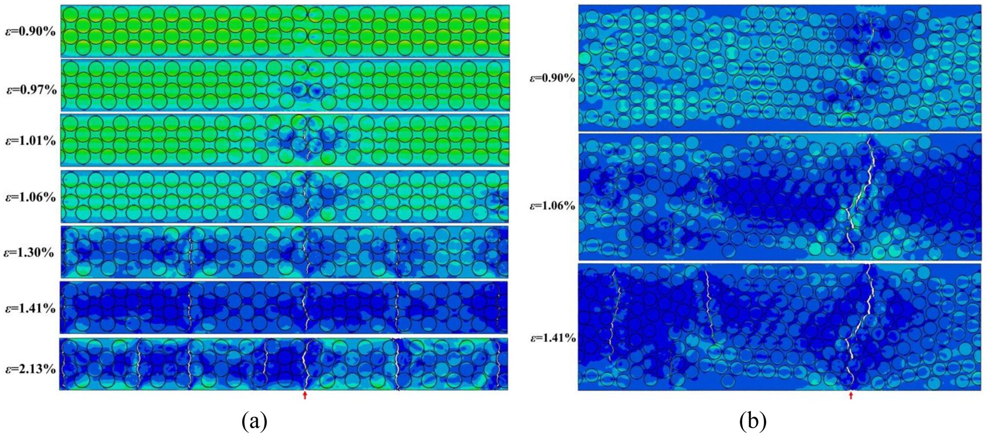
Transverse crack initiation, propagation, and suppression mechanisms in the mid-90° RVE for (a) b=0.025 mm, and (b) b=0.067 mm, with θ=0°. For better visualization of the damage behaviors, the homogenized outer plies are not shown in these figures.
In the case of a thicker mid-90° ply (for example b=0.067 mm), a transverse crack initiates by connecting interfacial debonding through matrix cracks at approximately ε=0.90%, and penetrates through the thickness direction at , as shown in Fig. 3(b). Examining comparisons between transverse crack extension in b=0.025 mm and b=0.067 mm, the transverse cracks in the thinner 90° ply show a more gradual manner. The number of transverse cracks and both increase with decreasing b of the mid-90° ply. For a thicker mid-90° ply, once a transverse crack is formed, it rapidly penetrates through the thickness and the sudden matrix crack extension leads to quicker stress relaxation, whereas in a thinner 90° ply, more transverse cracks develop and some of which do not completely penetrate through the thickness. This difference is clearly illustrated in Fig. 4(a), showing the normalized crack length, obtained by dividing the length of the transverse crack by the thickness b, as a function of applied strain. The length of the transverse crack is given by the base distance between the nodes in the tips of the longer transverse crack in the mid-90° RVE. The results show that the extension of transverse crack slows down with decreasing b of the mid-90° ply.
Figure 4.
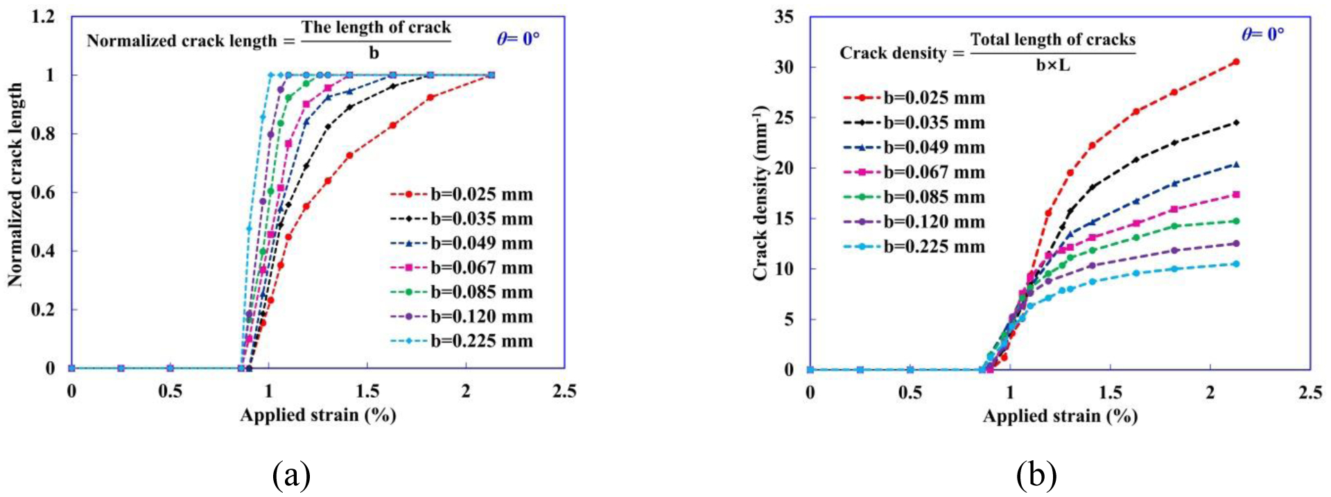
(a) Normalized crack length as a function of applied strain for different b. (b) Evolution of the crack density in the mid-90° ply with the applied strain.
Moreover, due to the constraining effect imposed by the adjacent 0° plies, the higher stress in the thinner mid-90° ply results in an increase of the crack density in the mid-90° ply, as shown in Fig. 4(b). The crack density is calculated independently by dividing the total length of transverse cracks by the cross-section area of mid-90° ply (i.e. b×L). The results show that the crack density increases with decreasing b of the mid-90° ply.
Fig. 5 (a)–(e) show transverse cracks indicated by the red arrow penetrate through the thickness of the mid-90° ply at for b=0.035 mm, 0.049 mm, 0.085 mm, 0.120 mm and 0.225 mm, respectively. The predicted are summarized in Table 3. The results show a general trend that thinner mid-90° ply leads to higher . In this study, the computationally predicted can be used together with Young’s modulus of transverse tension [21] to calculate the in-situ transverse tensile strength by assuming a linear elastic relationship of Eqn. (2). The results are summarized in Table 3.
| (1) |
Figure 5.
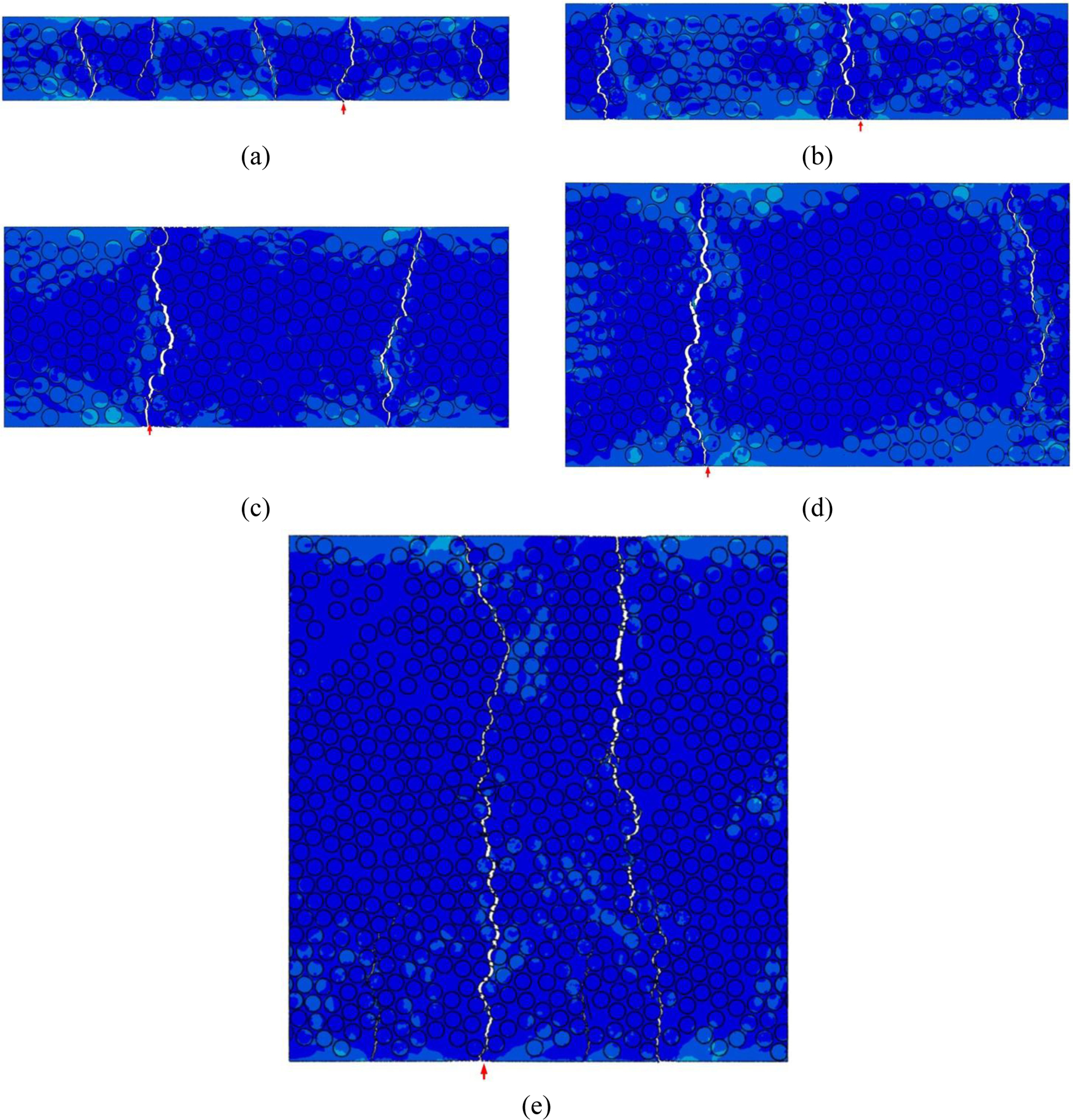
Ultimate failure at in the mide-90° RVE for θ=0° and (a) b=0.035 mm, ; (b) b=0.049 mm, ; (c) b=0.085 mm, ; (d) b=0.120 mm, ; (e) b=0.225 mm, .
Table 3.
Summary of the predicted and for different b with θ=0°.
| b (mm) | (%) | (MPa) |
|---|---|---|
| 0.025 | 2.13 | 195.96 |
| 0.035 | 1.82 | 167.44 |
| 0.049 | 1.63 | 149.96 |
| 0.067 | 1.41 | 129.72 |
| 0.085 | 1.25 | 115.00 |
| 0.120 | 1.12 | 103.04 |
| 0.225 | 0.98 | 90.16 |
In theoretical analysis, the in-situ effect is typically taken into account by using the analytical fracture mechanics theories [23]. In the case of very thin mid-90° ply, is given by Eqn. (2) [29, 44]:
| (2) |
where k is a parameter that depends on the stiffness of the adjacent plies [44]. For isotropic plies the parameter k depends on two Dundurs’ parameters [45]; one is defined by the mismatch of the Young modulus and the other by the mismatch of Poisson coefficients, and the latter one usually has a negligible influence. The mismatch of Young modulus can be expressed by the parameter α = Einner/Eouter. If the Young modulus of the outer plies is much larger than the one of the inner plies, then α approaches 0 and k = 2, as shown in a previous study [29]. By decreasing the Young modulus of the outer plies, k increases correspondingly. For a special situation in which the inner and outer materials have the same Young modulus, k = π. E22 and ν12 stand for the transverse elastic modulus and the in-plane Poisson’s ratio, respectively; GIc is fracture energy, GIc(L) = 0.0916 N/mm, which is adopted from the results of UD CFRP laminate in Ref. [46].
Considering pure mode-I loading, of a thin embedded ply can also be obtained from Eqn. (3) as derived in Ref. [47].
| (3) |
Dvorak and Laws [47] related of a thick mid-90° ply to the transverse tensile strength (YT) measured on an unconstrained UD ply as:
| (4) |
The results of obtained from computational results (Eqn. (1)) and theoretical results (Eqn. (2)–(3)) are plotted together with the broken horizontal line that is the prediction of for thick mid-90° ply according to Eqn. (4), as shown in Fig. 6(a). Comparing the results of between computational modeling and theoretical analysis, the results predicted from computational modeling agree well with the theoretical results of Eqn. (3). We note that the results predicted from Eqn. (2) tend to slightly overestimate the computational results.
Figure 6.

(a) Comparison of between the results of computational modeling and theoretical analysis as a function of the embedded mid-90° ply thickness b. (b) Comparisons between obtained from the Eqn. (5)–(6) and computational modeling.
In the work of Aveston and Kelly [48], can be calculated based upon the Griffith energy balance concept in conjunction with a one-dimensional shear-lag model to account for the load transfer resulting from a Model 1 crack spanning the mid-90° ply. The equation for of a thin mid-90° ply can be expressed as [4]:
| (5) |
Based on the work of Dvorak and Laws (Eqn. (4)), for a thick mid-90° ply can be derived as:
| (6) |
Fig. 6(b) shows the comparisons between predicted from the Eqn. (5)–(6) and computational results. Good agreements between the theoretical predictions and computational results are generally observed, indicating that the computational analyses here are sufficiently accurate.
It should be noted that the fracture mechanics theories developed to estimate the and usually neglect the effect of the stiffness of the neighboring outer plies that constrain the mid-90° ply. The values of and accounting for the stiffness of the outer layers can be more straightforwardly calculated using computational models with high resolution through the thickness of the ply in the next section.
3.1.2. The effect of orientation θ of the constraining plies
In this section, varying the orientation angle θ of homogenized outer plies, it is possible to assess the constraint effect imposed by different stiffness of neighboring plies on the mechanical response of [θ/90/θ] cross-ply laminates under transverse load. With increasing θ, the modulus of the homogenized outer plies in the X-direction decreases. Based on the computational results, we discover that the transverse crack propagates more drastically in the mid-90° ply (b=0.025 mm) with lower stiffness of adjacent layers (or larger angle θ of homogenized outer ply) at the same applied stain 0.95%, as shown in Fig. 7(a), indicating that transverse crack propagation behavior in the thin mid-90°layer is influenced by a change in stiffness caused by the ply angle θ of adjacent layers. However, with larger thickness b of mid-90° ply, for instance, 0.085 mm, we found that increasing the stiffness of adjacent layers shows less effect on transverse crack propagation in the mid-90° ply, as shown in Fig. 7(b). The same trend can be observed by comparing the normalized crack length in mid-90° ply with different θ for b=0.025mm and 0.085 mm, as shown in Fig. 8(a) and (b).
Figure 7.
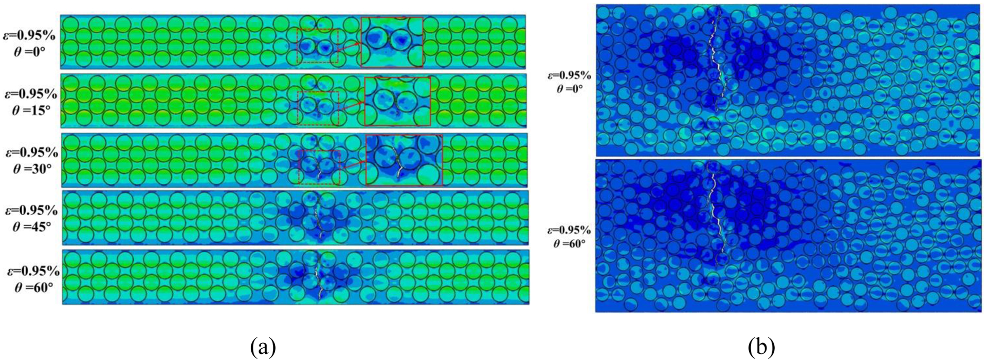
The effect of ply angle θ of adjacent layers on the transverse crack propagation in mid-90° ply with (a) b=0.025 mm and (b) b=0.085 mm at the applied strain ε=0.95%.
Figure 8.
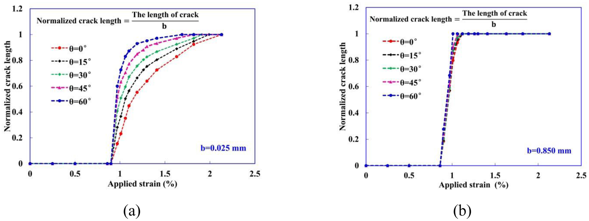
Normalized crack length in mid-90° ply with different θ for (a) b=0.025mm and (b) 0.085 mm as a function of applied strain.
Fig. 9 shows the ultimate failure modes of the mid-90° ply with different θ and b at . A more dispersed type of damage is observed in thin mid-90° ply with high stiffness of neighboring plies. This is the result of a less pronounced stress relaxation due to the constraining effect imposed by the adjacent plies, causing the development of more dispersed ply damage instead of localized transverse cracking, as shown in Fig. 9(a). Upon onset of transverse crack, the stress relaxation is much easier in the thicker transverse plies with lower stiffness of neighboring plies. This is due to that the constraining effect imposed by the adjacent plies on the thicker mid-90° ply is not sufficient to delay transverse crack growth through the thickness, as shown in Fig. 9(b). On the other hand, the higher stress levels are more easily maintained in thinner mid-90° plies, which tend to diffuse transverse damage onset and growth before the earlier cracks penetrating through, thus leading to an increase of and transverse crack density.
Figure 9.
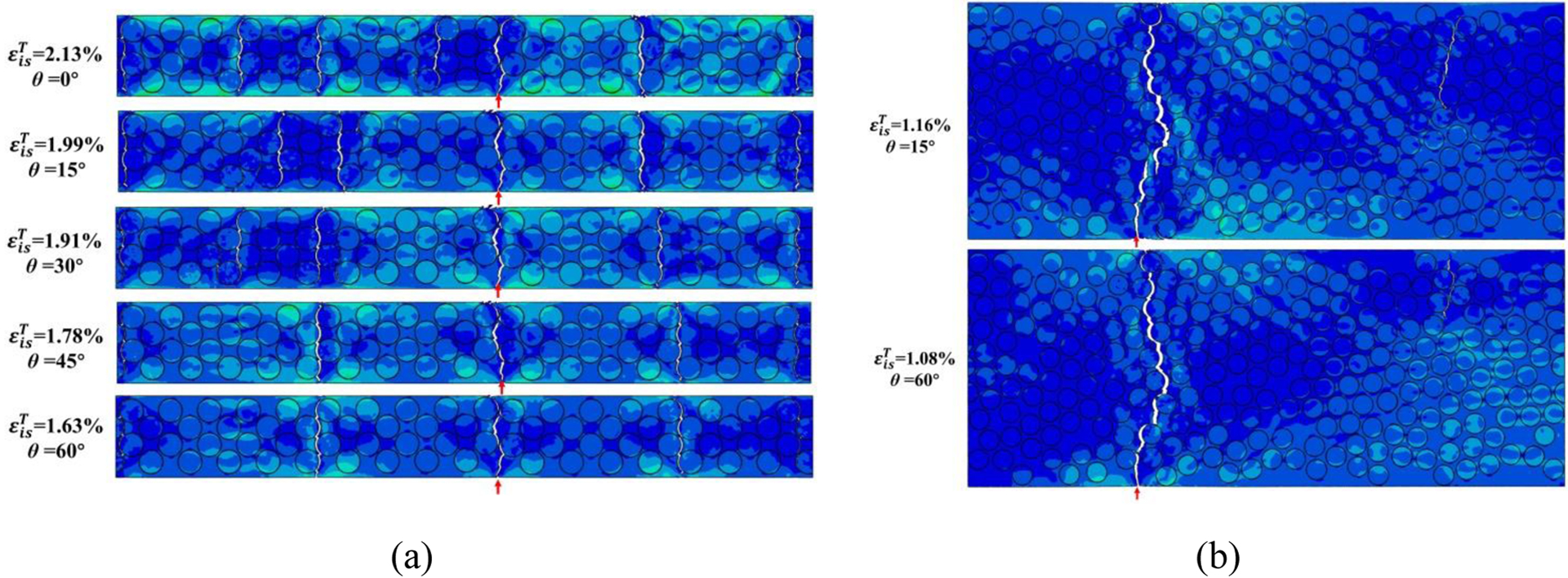
The ultimate failure modes of the mid-90° ply with different θ at in-situ transverse tensile strain for (a) b=0.025 mm, and (b) b=0.085 mm.
Fig. 10(a)–(b) and Table 4 show the summary of the predicted for different thickness b of mid-90° ply and orientation angle θ of homogenized outer plies. The results indicate that is not only dependent on the thickness b of mid-90° ply, but also dependent on the ply angle θ of adjacent layers. By decreasing b and θ, we see an increase in as shown in Fig. 10(a). For the same thickness of the mid-90° ply, decreases with increasing θ of homogenized outer plies from 0° to 60°. Furthermore, the decreasing rate of decays with the increase b of the mid-90° ply. remains nearly a constant (90 MPa) when b=0.225 mm, as shown in Fig. 10(b). By comparing the results of the computational macro/micro-scale framework with the experimental results of T300/934 [±θ/90n/±θ] laminates in Ref. [4] shown in Fig. 10(c) and (d), the same trend have been found, emphasizing the accuracy of the computational models.
Figure 10.
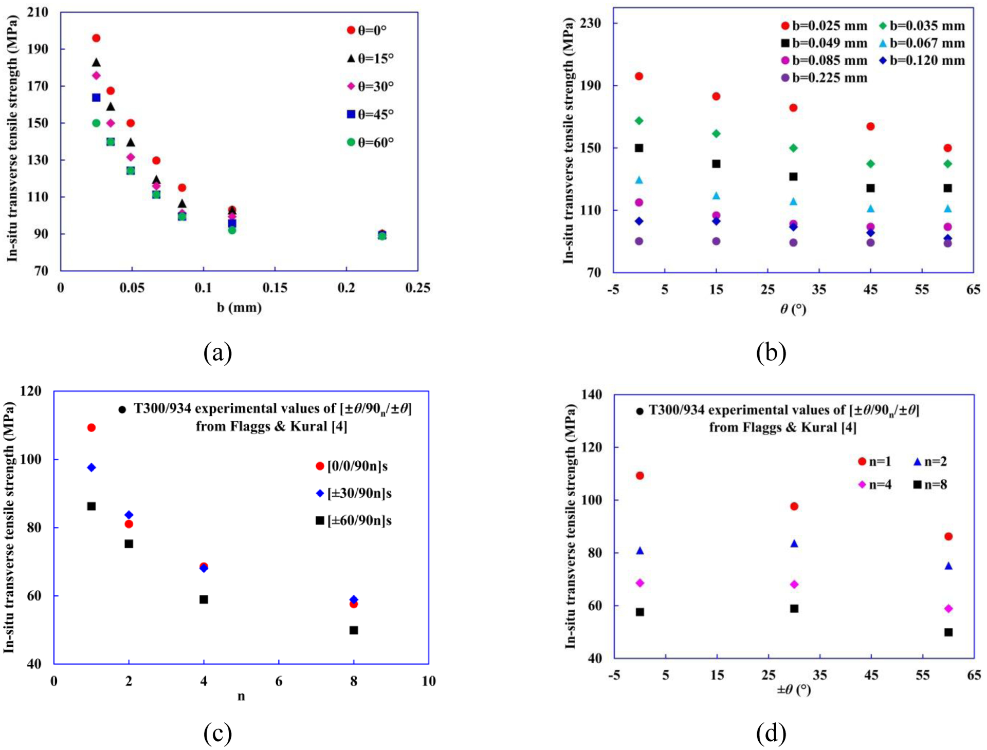
(a)–(b) Computational results and (c)–(d) experimental results [4] of as a function of mid-90° ply thickness b (or n [4]) and the orientation angle θ of adjacent plies.
Table 4.
Computational results of and for different b and θ.
| (mm) | θ (°) | |||||||||
|---|---|---|---|---|---|---|---|---|---|---|
| 0 | 15 | 30 | 45 | 60 | ||||||
| (%) | (MPa) | (%) | (MPa) | (%) | (MPa) | (%) | (MPa) | (%) | (MPa) | |
| 0.025 | 2.13 | 195.96 | 1.99 | 183.08 | 1.91 | 175.72 | 1.78 | 163.76 | 1.63 | 149.96 |
| 0.035 | 1.82 | 167.44 | 1.73 | 159.16 | 1.63 | 149.96 | 1.52 | 139.84 | 1.52 | 139.84 |
| 0.049 | 1.63 | 149.96 | 1.52 | 139.84 | 1.43 | 131.56 | 1.35 | 124.20 | 1.35 | 124.20 |
| 0.067 | 1.41 | 129.72 | 1.3 | 119.60 | 1.26 | 115.92 | 1.21 | 111.32 | 1.21 | 111.32 |
| 0.085 | 1.25 | 115.00 | 1.16 | 106.72 | 1.10 | 101.20 | 1.08 | 99.36 | 1.08 | 99.36 |
| 0.120 | 1.12 | 103.04 | 1.12 | 103.04 | 1.08 | 99.36 | 1.04 | 95.68 | 1.00 | 92.00 |
| 0.225 | 0.98 | 90.16 | 0.98 | 90.16 | 0.97 | 89.24 | 0.97 | 89.24 | 0.97 | 88.78 |
Based on the in-situ transverse tensile strength formula proposed by Chang et al. [49] and Wang et al. [50], we further propose an empirical formula for calculating the ratio of as a function of mid-90° ply thickness b and different ply angle (Δθd [0, π/2]) between mid-ply and adjacent ply:
| (7) |
where d is the fiber diameter. A and B are fitting parameters, which will be obtained based on computational results.
The constraining effect of the neighboring plies on the strengths of the mid-ply is governed by the second terms on the right-hand side of Eqn. (7). The variations of with the different orientation angles between mid-ply and adjacent ply are depicted by sin|Δθd|. We introduce sin|Δθd| and b/d in the parenthesis considering the fact that the dependence of constraining effect on the different stiffness between mid-ply and neighboring ply, also correlates with the ply thickness b. This also makes it possible to fit for both A and B by using one typical Δθd value (Δθd = 90°), as shown in Fig. 11(a). In fact, the obtained A and B values used in Eqn. (7) yield good agreements for other ply angle laminates as well, as shown in Fig. 11(b). The ratio of approaches to 1 when the thickness of mid-90° ply b becomes much larger than d or Δθd = 0°, which corresponds to a case of pure UD 90° ply.
Figure 11.
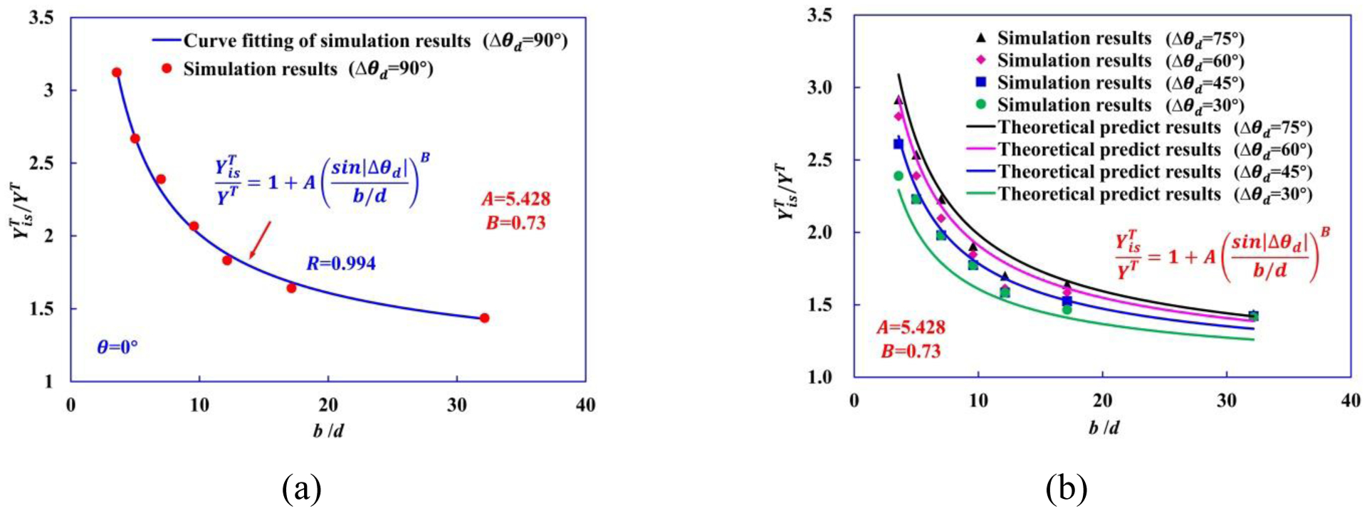
(a) Material parameters of Eqn. (7) are determined as A=5.428, B=0.73 by curve fitting of computational results of Δθd = 90°. (b) Comparison between theoretical predictions of and computational data for Δθd = 75°, Δθd = 60°, Δθd = 45°, and Δθd = 30°.
3.2. Cross-ply laminates under transverse compressive load
As shown in experimental results under transverse compression (Fig. 12(a) and (b)), due to the constraining effect imposed by the adjacent 0° plies, the angle of matrix crack in the mid-90° ply of [0/90/0] cross-ply laminates is about 66.78° with respect to the thickness direction, which is slightly larger than the typical orientation value (57.5°) in the UD CFRP composites under transverse compression. The difference between the two angles is associated with the effect of the adjacent 0° plies on the failure mechanisms of the mid-90° ply in a [0/90/0] cross-ply laminate under transverse compressive loading.
Figure 12.
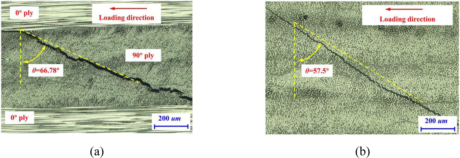
Optical microscopy images of the transverse matrix cracks in the (a) mid-90° ply of the cross-ply laminates, and (b) bulk UD composites under transverse compression.
To explore the constraining effect of the neighboring plies on the orientation of matrix crack in the mid-90° ply, 3D hybrid micro-macro models of cross-ply laminates with a layup of [θ/90/θ] (θ=0°, 15°, 30°, 45°, and 60°) and pure 90° UD RVE model under transverse compressive load are constructed, as shown in Fig. 13(a) and (b), respectively. The hybrid micro-macro [θ/90/θ] model consists of a micromechanics RVE model of the mid-90° ply, two adjacent homogenized θ° plies, and the interfaces between the plies. The length (X-direction), width (Z-direction) of the computational model and the thickness t of each individual outer ply are constant and equal to 60R (0.21 mm), R (0.0035 mm), and 60R throughout the analysis. The thickness b (Y-direction) of micro-model mid-90° ply shown in Fig. 13(a) is 0.049 mm. The dimensions of the pure 90° UD RVE model are the same as those of the mid-90° ply in the hybrid micro-macro model, as shown in Fig. 13(b).
Figure 13.
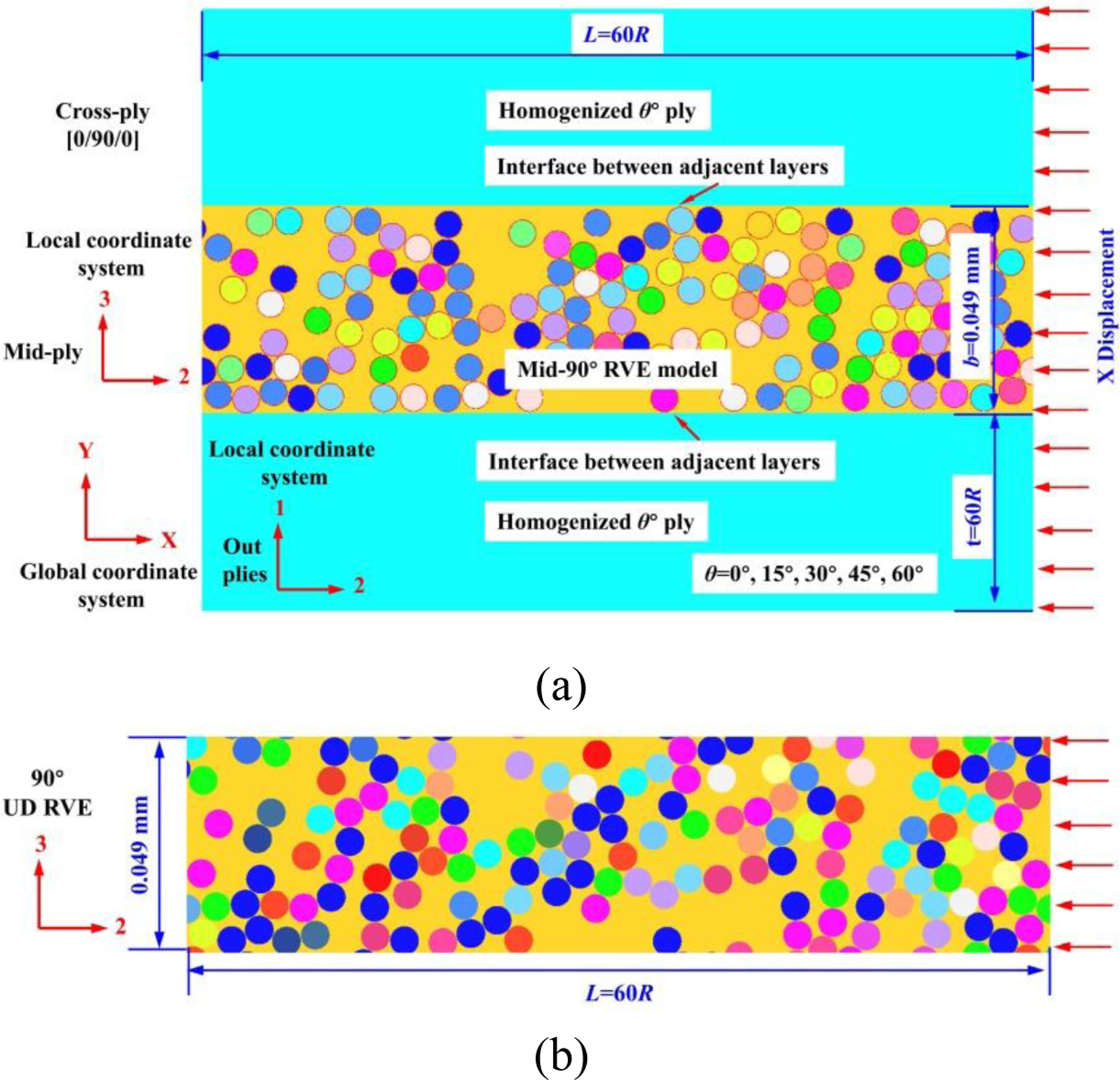
Schematic diagram of (a) hybrid micro-macro model for a laminate with a layup of [θ/90/θ], and (b) RVE model for 90° UD composites.
Fig. 14 shows the contour plots of the matrix equivalent plastic strain in the mid-90° ply of hybrid micro-macro [0/90/0] model and the 90° UD RVE model. The results show that the initiation and propagation of shear band in the mid-90° ply of hybrid micro-macro [0/90/0] model and 90° UD RVE model both are dominated by interface cracking and large plastic deformation in the interphase region as well as matrix near the locations where the interfacial debonding initiates. This leads to a localized band of damage in a plane by the coalescence of adjacent interfacial and matrix cracks not aligned with the compressive loading direction. Comparing the failure process in the mid-90° ply of hybrid micro-macro model and the 90° UD RVE model without constraint, a transverse crack suppression effect can be clearly identified in the mid-90° ply of the cross-ply laminates.
Figure 14.
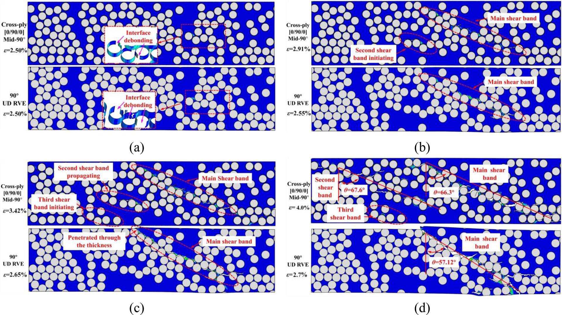
Contour plots of the matrix equivalent plastic strain and failure modes in the mid-90° ply of hybrid micro-macro [0/90/0] model and 90° UD RVE model at different applied strains.
For the pure 90° UD RVE model, interfacial debonding initiates at the locations which are offset from the poles of the fibers at ε=2.50% (Fig. 14(a)). Then, plastic deformation occurs in both interphase region and matrix near the interfacial cracks at ε=2.55% (Fig. 14(b)), and matrix cracks propagate through the laminate thickness at ε=2.65% (Fig. 14(c)). Finally, at ε=2.70%, matrix cracks at different locations are connected to form a main crack, which is the plastic shear band, leading to the strain energy gets dissipated through quick crack propagation (Fig. 14(d)). In contrast, for the mid-90° ply in [0/90/0] cross-ply laminates, matrix cracking extends gradually, without completely penetrating through the thickness, making stress relaxation much more constrained. This happens because the constraining effect imposed by the adjacent 0° plies on the mid-90° ply delays the transverse damage growth in the thickness direction. The higher stress field maintained in the mid-90° ply of [0/90/0] cross-ply laminates also leads to additional shear band onset and growth before the earliest main shear band has penetrated, as shown in Fig. 14(b) and (c). Furthermore, the higher stress levels maintained in the mid-90° ply also tends to increase the angle of the shear band. Fig. 14(d) shows the comparison of the shear band evolution in the mid-90° ply of the [0/90/0] laminates and 90° UD RVE model. The angle of the shear band orientation is about 66.3°~67.6° in the mid-90° ply of [0/90/0] cross-ply laminates, which is greater than the orientation of shear band (57.12°) in the 90° UD RVE model without the adjacent 0° plies. Moreover, the predicted angles of the shear band orientation in the mid-90° ply of hybrid micro-macro [0/90/0] model and the 90° UD RVE model are very close to the experimental results shown in Fig. 12(a) and (b).
In the case of cross-ply laminates with the ply angle θ=15°, 30°, 45°, and 60°, similar shear band damage pattern and angle of the main shear band can be observed. But we can find that the in-situ transverse compressive failure strains is higher for greater stiffness of adjacent layers (decreasing θ), as shown in Fig. 15(a) and (b). Comparing them with θ=0° shown in Fig. 14(d), a transverse crack suppression effect can be clearly identified. As the orientation angle θ decreases (or as the stiffness of adjacent layers increases), damage progression becomes more and more gradual, and through-the-thickness fracture is delayed. Upon the onset of main shear band, the stress relaxation is more significant in mid-90° ply with lower stiffness of adjacent layers than in the higher ones. The higher stress levels maintained in the mid-90°ply result in the initiation and propagation of new shear bands before main shear band penetrating through the thickness. As the orientation angle θ decreases, the number of localized shear bands also increases.
Figure 15.

Contour plots of the equivalent plastic strain and failure modes in the mid-90° ply with homogenized outer plies of different orientation angles (a) θ=15°, 30° and (b) θ=45°, 60° of at applied strains (only the mid-90° ply is shown).
In the absence of experimental in-situ information, different 3D hybrid micro-macro models of [θ/90/θ] cross-ply laminates with various thickness b=0.025 mm, 0.035 mm, 0.067 mm, 0.085 mm, 0.120 mm, 0.225 mm of mid-90° ply and the orientation angle θ=0°, 15°, 30°, 45°, 60° of homogenized outer ply are generated to systematically study the in-situ effect on constrained plies subjected to transverse compressive load, similar to the cases of transverse tension in Section 3.1. The in-situ transverse compressive strengths from the computational models [22] are calculated based on the in-situ transverse compressive failure strain corresponding to the development of through-the-thickness shear band failure, and Young’s modulus of the transverse compression :
| (8) |
The computational results are summarized in Table 5.
Table 5.
The computational results of and for different b and θ.
| b (mm) | θ (°) | |||||||||
|---|---|---|---|---|---|---|---|---|---|---|
| 0 | 15 | 30 | 45 | 60 | ||||||
| (%) | (MPa) | (%) | (MPa) | (%) | (MPa) | (%) | (MPa) | (%) | (MPa) | |
| 0.025 | 4.71 | 437.56 | 4.40 | 408.80 | 4.22 | 392.37 | 3.94 | 365.66 | 3.60 | 334.85 |
| 0.035 | 4.32 | 401.33 | 4.11 | 381.48 | 3.87 | 359.43 | 3.61 | 335.18 | 3.41 | 316.79 |
| 0.049 | 4.01 | 372.53 | 3.74 | 347.39 | 3.59 | 333.51 | 3.35 | 311.22 | 3.20 | 297.28 |
| 0.067 | 3.61 | 335.37 | 3.45 | 320.51 | 3.25 | 301.93 | 3.12 | 289.94 | 2.98 | 276.84 |
| 0.085 | 3.32 | 308.43 | 3.15 | 292.64 | 3.02 | 280.56 | 2.94 | 273.13 | 2.83 | 262.91 |
| 0.120 | 3.03 | 281.49 | 2.95 | 274.06 | 2.84 | 264.27 | 2.79 | 259.19 | 2.76 | 256.40 |
| 0.225 | 2.78 | 258.26 | 2.76 | 256.40 | 2.73 | 253.62 | 2.73 | 253.62 | 2.71 | 251.76 |
Fig. 16(a) and (b) show the predicted distribution of (YC = 185.9 MPa) with various b and θ, respectively. The results show that the predicted increase with decreasing b and θ. For the same thickness b, decrease with increasing θ, while the decreasing rates of drop with larger b, until remains almost a constant (1.4) when b=0.225 mm.
Figure 16.
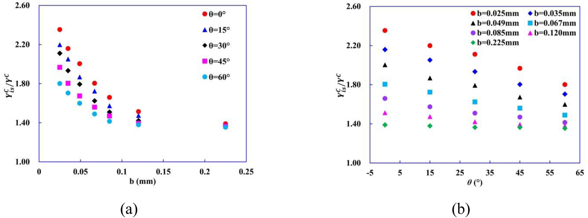
Ratios of to YC vs. (a) thickness b of mid-90° ply and (b) orientation angle θ of homogenized outer plies.
According to Catalanotti et al. [1], for θ=0° is given explicitly as:
| (9) |
where a0 is the shear band angle in pure 90° UD laminates (57.12°) and ηL is the friction coefficient, ηL = 0.36 [1].
Comparing the predictions of from computational models with the results obtained from analytical model (Eqn. (9)) for θ=0°, good agreements are generally observed in Fig. 17.
Figure 17.
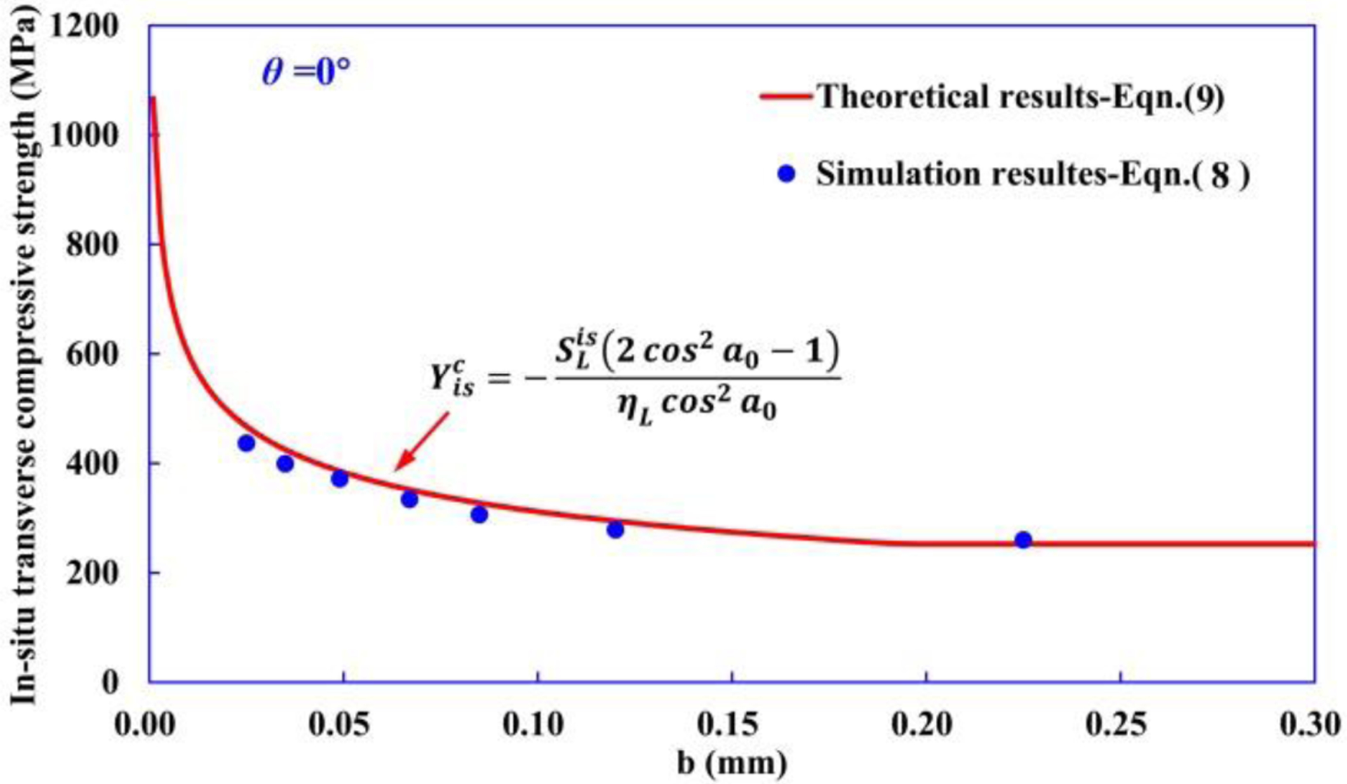
Comparison of in-situ transverse compressive strength obtained from the computational modeling and analytical analysis.
As discussed above, in laminated composites strongly depend on the thickness b of the mid-90° ply and orientation angle θ of homogenized outer plies. Hence, an expression similar to Eqn. (7) for is proposed as a function of b and Δθd to evaluate the magnitude of in-situ effect, i.e.,
| (10) |
where C and D are fitting parameters.
The Eqn. (10) agrees with the simulation results of Δθd = 90° very well with C=2.905 and D=0.60, as shown in Fig. 18(a). Fig. 18(b) shows that the predicted using Eqn. (10) for Δθd = 75°, 60°, 45°, and 30° are all in good agreement with computational results, indicating that the proposed theoretical model of is sufficient to describe as a function of b and Δθd.
Figure 18.
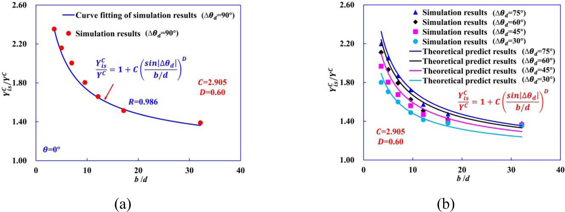
(a) Eqn. (10) is fitted to the computational results of Δθd = 90°. (b) Comparison between Eqn. (10) and computational data for Δθd = 75°, 60°, 45°, and 30°.
3.3. Cross-ply laminates under three-point bending load
In a sandwich-typed [0/90/0] structure, the strong and stiff outer-0° plies carry most of the in-plane shear and bending loads, while the mid-90° ply mainly bears the out-of-plane shear and normal loads [51]. By carefully constructing a [0/90/0] laminated sandwich-typed beam specimen with a low span-to-thickness ratio under three-point bending can be exploited to achieve out-of-plane shear failure in the mid-90° ply [52–56]. For a sandwich-beam under three-point bending, the normal stress and shear stress show discontinuities, owing to the difference in elastic constants between the adjacent layers, as shown in Fig. 19. As the elastic modulus of the outer-0° ply is significantly larger than that of the mid-90° ply (Eouter>>Emid) in the global X-direction, the normal stress distributions in outer-0° and mid-90° ply become more disparate. This in turn causes the out-of-plane shear stress distribution to become more uniform within mid-90° ply. Likewise, as the ratio of mid-90° ply’s thickness b to outer-0° ply’s thickness touter (b/touter) is increased, the out-of-plane shear stress distribution in the mid-90° ply becomes more “peaked” or pronounced, lowering the shear stress at the interface between mid-90° and outer-0° plies [53].
Figure 19.
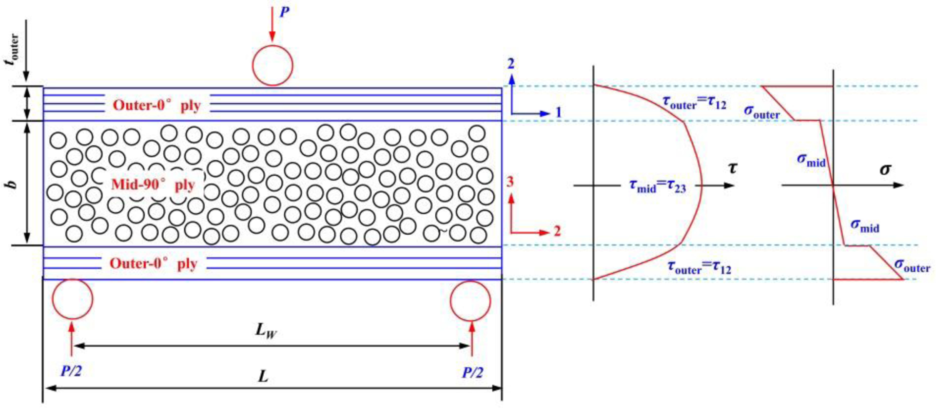
Illustration of short sandwich beam and related shear and normal stress.
The out-of-plane shear strength of the mid-90° ply can be calculated as [53]:
| (11) |
where P is the applied load; touter is the thickness of a single outer layer; b is the total thickness of the mid-90° ply; W is the sample width; Eouter and Emid are the elastic moduli of outer-0° ply and mid-90°, respectively.
The experimentally observed angle of crack propagation in the mid-90° ply is 56~57° [53]. However, for UD CFRP composite subjected to out-of-plane shear stress, the shear stress τ23 is equivalent to a pair of tensile and compressive stresses (σt, σc) at 45°. Since the transverse tensile strength is almost invariably one of the lowest material strengths, sample failures should take the form of a 45° crack [53]. This difference in crack orientation also illustrates the constraining effect of adjacent 0° plies on mid-90° ply in a [0/90/0] cross-ply laminate under out-of-plane shear loading. Moreover, the experimental results showed that of sandwich-typed specimen is affected strongly by the span-to-depth ratio (LW/(2b + 4touter)), i.e., decrease with increasing LW/(2b + 4touter) [55].
In order to study the constraining effect of the neighboring plies on the crack orientation in the mid-90° ply, 3D hybrid micro-macro model of [0/90/0] cross-ply laminates subjected to three-point bending load and pure 90° UD RVE model under out-of-plane shear load are developed. The hybrid micro-macro [0/90/0] model consists of a micro-scale model of the mid-90° ply and two adjacent macro-scale 0° plies, as shown in Fig. 20(a). A tie constraint ties the surfaces of mid-90° ply and outer-0° ply together, avoiding other possible failure mechanisms. In the sandwich-typed [0/90/0] structure, Dai and Thomas Hahn [57] and Awad et al. [58] indicated that shorter span LW exhibited higher out-of-plane shear stress in the mid-90° ply than specimens with longer span. Furthermore, experimental results showed that the out-of-plane shear stress in the mid-90° ply is more dominant than flexural stress when LW/(2b + 4touter) = 1 for the short sandwich beams under three-point bending load [59]. Based on those results, the thickness (Y-direction) b of the mid-90° ply, length L, and span LW (X-direction) of the hybrid micro-macro model are chosen to be 0.049 mm, 60R (0.21 mm) and 54R (0.189 mm) in this study. Then, we achieve LW/(2b + 4touter) ≈ 1.1. The width (Z-direction) W of RVE model of the mid-90° ply and the thickness touter of each individual outer ply are constant and equal to R (0.0035 mm) and 5R (0.0105 mm). For the pure 90° UD RVE model, the width, length and thickness are R (0.0035 mm), 15R, and 15R (0.0525 mm), as shown in Fig. 20(b).
Figure 20.
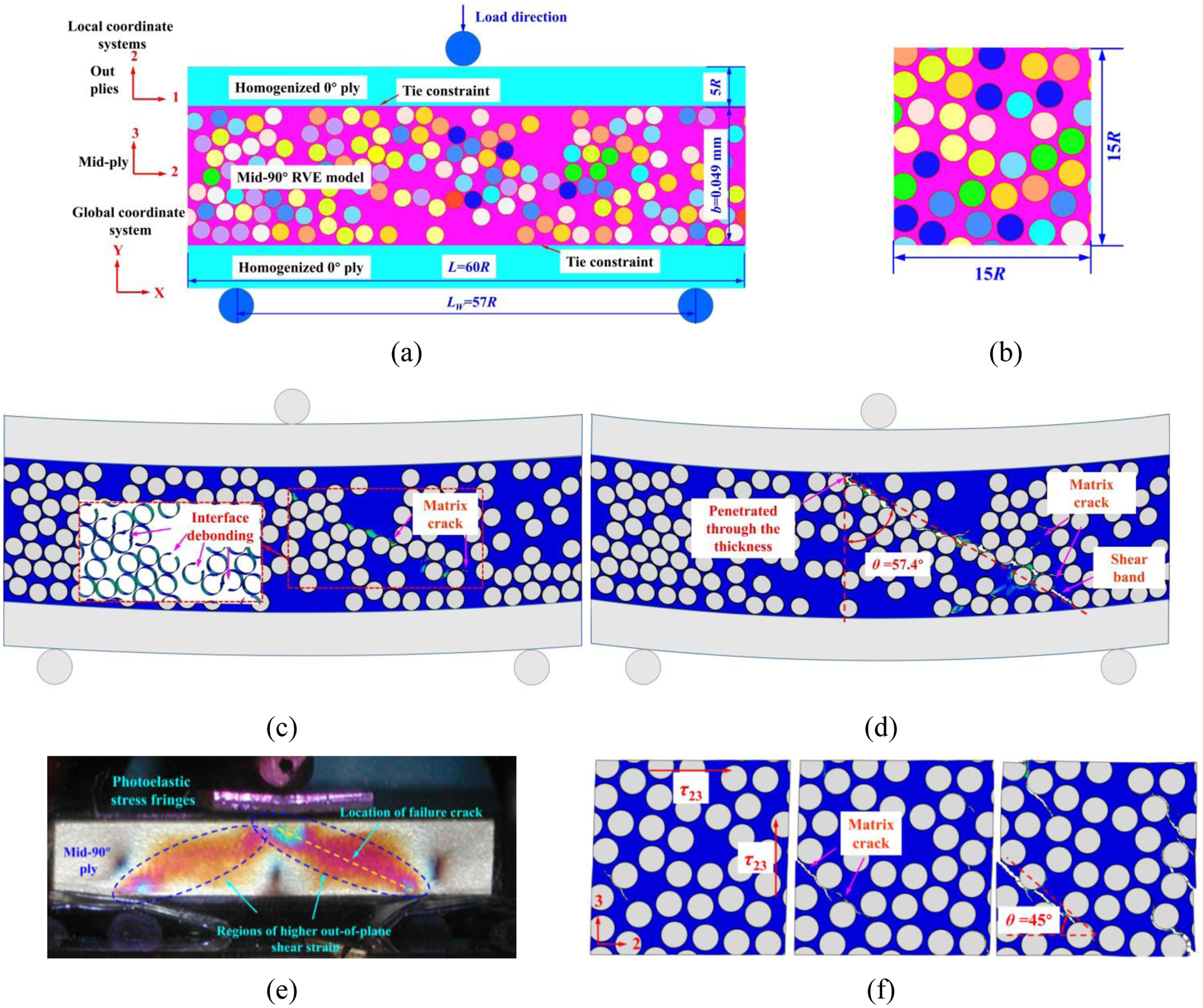
Schematic diagrams of (a) hybrid micro-macro model for a laminate with a layup of [0/90/0] under three-point bending load, and (b) 90° UD RVE model. (c)–(d) Contour plots of the equivalent plastic strain and failure modes in the matrix of mid-90° ply. (e) Photoelastic fringes as observed during short sandwich beam three-point-bending test. (f) Failure process of a pure 90° UD RVE model subjected to out-of-plane shear load.
The computational results show that the hybrid micro-macro model of [0/90/0] cross-ply laminates exhibits a catastrophic failure due to the formation of a shear matrix crack in the mid-90° ply under three-point bending load. More specifically, interfacial cracks and shear matrix cracks initiate and propagate through the mid-90° ply at the location of the maximum out-of-plane shear stress, as shown in Fig. 20(c). The constraining effect imposed by the adjacent 0° plies on the mid-90° ply delays the shear crack from penetrating through the thickness direction. Moreover, the higher stress levels maintained in the mid-90° ply leads to an increase in the angle of the shear crack. As indicated in Fig. 20(d), the inclination of shear cracks is approximately 57.4°, presented a good agreement with the experimental results (Fig. 20(e)), showing that the hybrid micro-macro model can reasonably estimate the failure behaviors of laminated sandwich-typed specimen under three-point bending load. In comparison, for the pure 90° UD RVE model without constraint under out-of-plane shear load, initial matrix cracks are concentrated in the vicinities of interface cracks and propagate through the RVE by forming a fracture path along 45° with respect to the applied shear loading direction, as shown in Fig. 20(f).
The in-situ out-of-plane shear strength for θ=0° (Δθd = 90°) proposed by Catalanotti et al. [1, 28] is shown to depend on as:
| (12) |
where a0 is the fracture angle under pure compression (a0 = 57.12°), ηL is the friction coefficient in the longitudinal direction, ηL = 0.36, and is the in-situ in-plane shear strength, which can be calculated by using the fracture mechanics model proposed by Camanho et al. [3]:
| (13) |
where β is a parameter that defines the nonlinearity of the shear stress-strain relation [60], G12 is the in-plane shear modulus and the parameter φ is defined according to the configuration of a given ply. The parameter β can be determined based on the results from the micromechanics UD RVE model subjected to pure in-plane shear and fitting the polynomial approximation proposed by Hahn and Tsai [60] to the shear stress-shear strain curves obtained with three different RVEs. For CFRP composites used in the present study specifically, shear non-linearity parameter β has been calculated to be 3.91 × 10⁻⁸ MPa−3.
Similar behavior to and has been observed from experiments for distribution in laminated composites [61, 62], i.e., strongly depends on the thickness of the ply b and different ply angle (Δθd) between mid-ply and adjacent ply. In this section, the ratio of and are proposed as a function of b and Δθd same as described in the earlier Sections 3.1–3.2:
| (14) |
| (15) |
where E, F, G and H are fitting parameters. They are fitted according to the theoretical data obtained using Eqn. (12) and (13) with Δθd = 90°, and we obtain the values of E=2.90, F=0.539, G=5.01, and H=0.376.
Fig. 21(a) and (b) show a typical distribution of and as a function of Δθd and the mid-90° ply thickness b using Eqn. (14) and (15), respectively. We can observe that Eqn. (14) and (15) can sufficiently predict the trend of and depending on the thickness of the mid-90° ply. We note that more direct experimental or computational data will be required to further validate the dependence on different ply orientation between mid-90°and adjacent ply, and this would require more reliable in-situ test or more accurate computational approach to measure the in-situ strengths.
Figure 21.
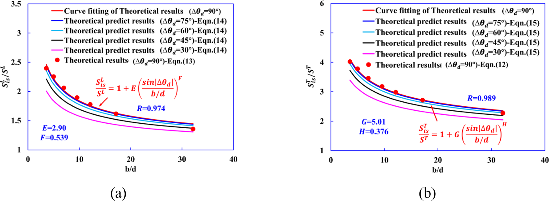
The distribution of (a) and (b) as a function of b and Δθd.
3.4. In-situ longitudinal compressive strength
In our previous study [10, 12], the experimental results reveal that the main failure mechanism in UD laminates is fiber kinking failure, which is initiated by imperfections, i.e., fiber waviness; while fiber kinking, matrix cracking, and delamination are co-existing failure mechanisms in the [90/0/90] cross-ply laminates. Specifically, the fractured 0° layers in the middle of the laminate exhibit two kink-bands and show a “wedge” shape with the high stress concentrations due to the constraining effects by the adjacent 90° layers, as shown in Fig. 22(a).
Figure 22.

(a) Typical failure modes of pure 0° UD laminates and [90/0/90] cross-ply laminates under longitudinal compressive loading [10, 12]. (b) The variation of versus for different θwav_max based on Eqn. (16).
In this section, based on the longitudinal compressive strength Xc formulae proposed by Pinho and coworkers [63], we propose a formula for calculating in-situ longitudinal compressive strength depending on the maximum fiber waviness angle θwav_max and in-situ in-plane shear strength :
| (16) |
where Vf is fiber volume fraction, Gm is matrix shear modulus. can be calculated based on Eqn. (13).
Afterwards, based on results of for θ=0° (Δθd = 90°) (Eqn. (14)), Fig. 22(b) gives a conservative estimate of based on Eqn. (16) for θwav_max =0.45°, 0.90°, 1.80°, 3.60° and 5.40°. The results show that decrease with increasing θwav_max, indicating that is very sensitive to the initial fiber waviness introduced during manufacturing processes.
4. Failure criteria considering the in-situ strengths
There exist numerous failure criteria which are usually stress-based and expressed as equations, including fully interactive criteria (Tsai Wu [64], Tsai Hill [65]) and failure mode based criteria (Hashin [66], Puck [67], and Pinho-LaRC04 [68, 69]. In a recent study, Daniel-NU failure theory [70, 71], which is based on micromechanical matrix failure mechanisms, allows the prediction of failure envelopes under multi-axial stress states at different strain rates. In the first world-wide failure exercise for composite laminates, organized by Hinton et al. [72], Puck’s theory was found to be one of the five leading failure theories among all the nineteen participating theories [73]. Despite its good performance, Puck’s theory predicts an initial failure stress of laminates that is significantly lower than experimental results [74], and it shows some discontinuities in the failure envelopes under certain load combinations. The reason might be largely because it does not consider the in-situ effect that the crack formation in very thin plies is delayed when they are embedded between stiff neighboring plies as shown in prior sections. Also, failure strength usually depends on the ply thickness and stacking sequence, but the effects of ply thickness and stacking sequence on the failure behaviors of laminated composites are one of the topics that have not been properly addressed in the world wide failure exercise [73]. Predictions obtained using basic strengths considerably underestimate the initial failure strength while the model with in-situ effects considered usually give a better agreement with test data [74]. The current way to consider in-situ effects is that the lamina transverse tensile strength is simply multiplied by 1.35 and the in-plane shear strength by 1.175 to include the in-situ effect in Puck’s theory [75] submitted to the second world-wide failure exercise [76]. Nevertheless, this method is in such an approximate manner that it cannot capture the realistic influence of the thickness of the lamina itself or that of the ply angles of the neighboring plies.
Thus, building upon the effort in this study and our previous RVE-based failure criteria [13], a new set of failure criteria for σ22-τ12, σ22-τ23, and σ11-τ12 considering the influence of both the thickness of the lamina and the ply angles of its neighboring plies is proposed for predicting laminated composites failure under multi-axial stress states, as summarized in Table 6.
Table 6.
Failure criteria of σ22-τ12, σ22-τ23, and σ11-τ12 considering in-situ strengths.
| Tension dominated failure (σ22 > 0) | ||
| Shear dominated failure |
|
|
| Compression dominated failure |
|
|
| Fiber-compression dominated failure (σ11 ≤ 0) | ||
|
| ||
In Table 6, and are transverse normal, in-plane shear and out-of-plane shear stress of the transition point for failure envelopes of σ22-τ12 and σ22-τ23. Failure envelopes of σ22-τ12, σ22-τ23, and σ11-τ12 predicted from in-situ-strength-based failure criteria are presented in Fig. 23(a)–(c). A comprehensive schematic diagram of the variations of , , , and as a function of b/d and Δθd is shown in Fig. 23(d)–(g), respectively. While the proposed in-situ-strength-based failure criteria can be used to predict failure for laminated composites, we note that additional experimental work is required to validate the predictions obtained for multi-axial stress states.
Figure 23.
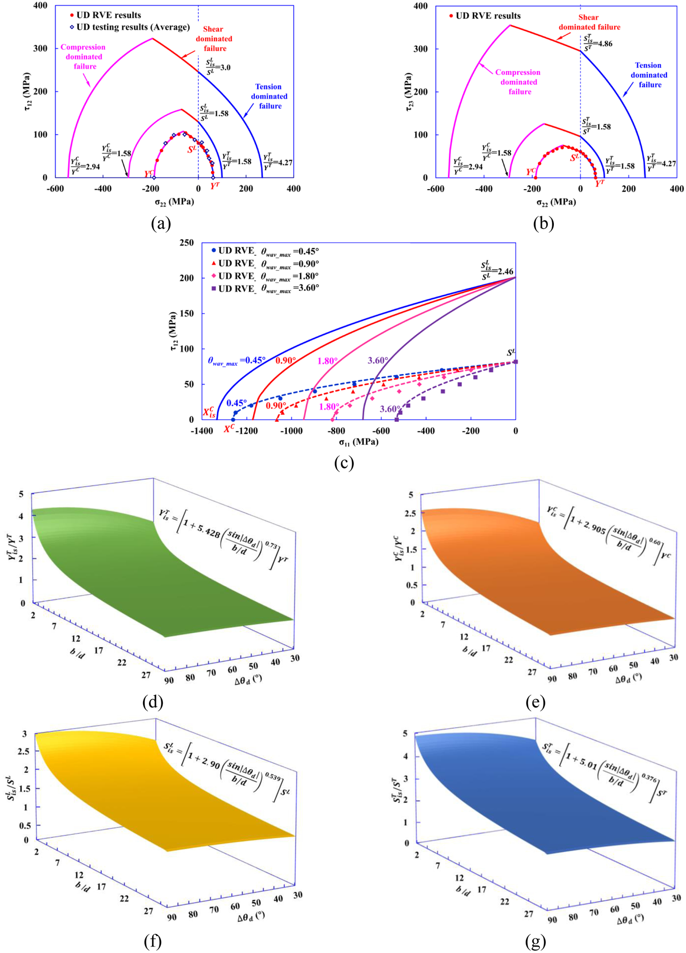
Failure envelopes of (a) σ22-τ12, (b) σ22-τ23, and (c) σ11-τ12 predicted from in-situ-strength-based failure criteria. A comprehensive schematic diagram of the variations of (d) , (e) , (f) , and (g) with changing b/d and Δθd.
5. Conclusions
In this work, the in-situ effect in cross-ply laminates and the corresponding failure mechanisms subjected to transverse tension, transverse compression, in-plane/out-of-plane shear, and longitudinal compression have been studied systematically using hybrid macro/micro-scale computational models. We demonstrate that the proposed framework is able to accurately capture the micro-mechanical response of mid-90° ply for cross-ply laminates, including (i) the mechanism of transverse cracking onset and propagation, (ii) the constraining effect observed in the laminar embedded in the cross-ply laminates, (iii) the gradual and slow stress relaxation and progressive transverse cracking observed in the thin mid-90° ply with high stiffness of neighboring plies, and consequent increase of the crack density for transverse tension and localized shear bands for transverse compression, and (vi) the quantitative in-situ effect, characterized by an increase in the applied stress needed to extend a transverse crack through the thickness of the mid-90° with decreasing mid-90° ply thickness b and orientation angle θ of homogenized outer plies.
Furthermore, we have validated the results of in-situ transverse tensile strain , strength , and in-situ transverse compressive strength obtained from computational models with analytical predictions found in the literature. We have also constructed the model of [0/90/0] cross-ply laminates under three-point bending load and [90/0/90] cross-ply laminates subjected to longitudinal compressive load using the demonstrated hybrid micro-macro approach. The results show that the constraining effect of 0° plies tends to increase the angle of shear band in the mid-90° ply of [0/90/0] cross-ply laminates, and due to the constraining effect imposed by the adjacent 90° plies, the kink-band in the mid-0° ply of [90/0/90] cross-ply laminates shows a wedge-shape. Furthermore, theoretical formulations of in-situ strengths , , , , and are proposed, with full consideration of the constraining effect of adjacent plies and the embedded laminar thickness. Finally, building upon these theoretical formulations, a new set of failure criteria for σ22-τ12, σ22-τ23, and σ11-τ12 accounting for the in-situ strengths are proposed to predict the strength of laminated composites under multi-axial stress states.
In conclusion, we have presented a thorough analysis of the in-situ effect present in laminated composites by combining computational, theoretical, and experimental investigations. The analyses and methods presented in this study provide valuable solutions to the great challenge of failure prediction for laminated composites used in structural applications.
Acknowledgments
The authors acknowledge support from the Ford Motor Company with funding from the U.S. Department of Energy’s Office of Energy Efficiency and Renewable Energy (EERE), under Award Number DE-EE0006867. Q. Sun acknowledges support from the China Scholarship Council (CSC). Z. Meng would like to acknowledge startup funds from Clemson University and SC TRIMH support (P20 GM121342).
References
- [1].Catalanotti G, Camanho P, Marques A. Three-dimensional failure criteria for fiber-reinforced laminates.Composite Structures. 2013;95:63–79. [Google Scholar]
- [2].Parvizi A, Garrett K, Bailey J. Constrained cracking in glass fibre-reinforced epoxy cross-ply laminates.Journal of Materials Science. 1978;13(1):195–201. [Google Scholar]
- [3].Camanho PP, Dávila CG, Pinho ST, Iannucci L, Robinson P. Prediction of in situ strengths and matrix cracking in composites under transverse tension and in-plane shear.Composites Part A: Applied Science and Manufacturing. 2006;37(2):165–76. [Google Scholar]
- [4].Flaggs DL, Kural MH. Experimental determination of the in situ transverse lamina strength in graphite/epoxy laminates.Journal of composite materials. 1982;16(2):103–16. [Google Scholar]
- [5].Amacher R, Cugnoni J, Botsis J, Sorensen L, Smith W, Dransfeld C. Thin ply composites: Experimental characterization and modeling of size-effects.Composites Science and Technology. 2014;101:121–32. [Google Scholar]
- [6].Zhou G, Sun Q, Meng Z, Li D, Peng Y, Zeng D, Su X. Experimental Investigation on the Effects of Fabric Architectures on Mechanical and Damage Behaviors of Carbon/Epoxy Woven Composites.Composite Structures. 2020:113366. [DOI] [PMC free article] [PubMed] [Google Scholar]
- [7].Zhou G, Sun Q, Li D, Meng Z, Peng Y, Zeng D, Su X. Effects of fabric architectures on mechanical and damage behaviors in carbon/epoxy woven composites under multiaxial stress states.Polymer Testing. 2020:106657. [Google Scholar]
- [8].Laux T, Gan KW, Dulieu-Barton JM, Thomsen OT. Ply thickness and fibre orientation effects in multidirectional composite laminates subjected to combined tension/compression and shear.Composites Part A: Applied Science and Manufacturing. 2020:105864. [Google Scholar]
- [9].Fallahi H, Taheri-Behrooz F, Asadi A. Nonlinear mechanical response of polymer matrix composites: a review.Polymer Reviews. 2020;60(1):42–85. [Google Scholar]
- [10].Sun Q, Guo H, Zhou G, Meng Z, Chen Z, Kang H, Keten S, Su X. Experimental and computational analysis of failure mechanisms in unidirectional carbon fiber reinforced polymer laminates under longitudinal compression loading.Composite Structures. 2018;203:335–48. [Google Scholar]
- [11].Sun Q, Meng Z, Zhou G, Lin S-P, Kang H, Keten S, Guo H, Su X. Multi-scale computational analysis of unidirectional carbon fiber reinforced polymer composites under various loading conditions.Composite Structures. 2018;196:30–43. [Google Scholar]
- [12].Sun Q, Zhou G, Guo H, Meng Z, Chen Z, Liu H, Kang H, Su X. Failure mechanisms of cross-ply carbon fiber reinforced polymer laminates under longitudinal compression with experimental and computational analyses.Composites Part B: Engineering. 2019;167:147–60. [Google Scholar]
- [13].Sun Q, Zhou G, Meng Z, Guo H, Chen Z, Liu H, Kang H, Keten S, Su X. Failure criteria of unidirectional carbon fiber reinforced polymer composites informed by a computational micromechanics model.Composites Science and Technology. 2019;172:81–95. [Google Scholar]
- [14].Sun Q, Zhou G, Meng Z, Jain M, Su X. An Integrated Computational Materials Engineering Framework to Analyze the Failure Behaviors of Carbon Fiber Reinforced Polymer Composites for Lightweight Vehicle Applications.Composites Science and Technology. 2020:108560. [DOI] [PMC free article] [PubMed] [Google Scholar]
- [15].Tang H, Chen H, Sun Q, Chen Z, Yan W. Experimental and computational analysis of structure-property relationship in carbon fiber reinforced polymer composites fabricated by selective laser sintering.Composites Part B: Engineering.204:108499. [Google Scholar]
- [16].Tang H, Chen Z, Xu H, Liu Z, Sun Q, Zhou G, Yan W, Han W, Su X. Computational micromechanics model based failure criteria for chopped carbon fiber sheet molding compound composites.Composites Science and Technology. 2020;200:108400. [Google Scholar]
- [17].Zhou G, Sun Q, Li D, Meng Z, Peng Y, Chen Z, Zeng D, Su X. Meso-scale modeling and damage analysis of carbon/epoxy woven fabric composite under in-plane tension and compression loadings.International Journal of Mechanical Sciences. 2020;190:105980. [DOI] [PMC free article] [PubMed] [Google Scholar]
- [18].Tang H, Chen Z, Avinesh O, Guo H, Meng Z, Engler-Pinto C, Kang H, Su X. Notch insensitivity in fatigue failure of chopped carbon fiber chip-reinforced composites using experimental and computational analysis.Composite Structures. 2020:112280. [DOI] [PMC free article] [PubMed] [Google Scholar]
- [19].Tang H, Zhou G, Chen Z, Huang L, Avery K, Li Y, Liu H, Guo H, Kang H, Zeng D. Fatigue behavior analysis and multi-scale modelling of chopped carbon fiber chip-reinforced composites under tension-tension loading condition.Composite Structures. 2019;215:85–97. [Google Scholar]
- [20].Saito H, Takeuchi H, Kimpara I. A study of crack suppression mechanism of thin-ply carbon-fiber-reinforced polymer laminate with mesoscopic numerical simulation.Journal of Composite Materials. 2014;48(17):2085–96. [Google Scholar]
- [21].Arteiro A, Catalanotti G, Melro A, Linde P, Camanho PP. Micro-mechanical analysis of the in situ effect in polymer composite laminates.Composite Structures. 2014;116:827–40. [Google Scholar]
- [22].Arteiro A, Catalanotti G, Melro A, Linde P, Camanho P. Micro-mechanical analysis of the effect of ply thickness on the transverse compressive strength of polymer composites.Composites Part A: Applied Science and Manufacturing. 2015;79:127–37. [Google Scholar]
- [23].Arteiro A, Catalanotti G, Reinoso J, Linde P, Camanho PP. Simulation of the mechanical response of thin-ply composites: from computational micro-mechanics to structural analysis.Archives of Computational Methods in Engineering. 2019;26(5):1445–87. [Google Scholar]
- [24].Herráez M, Mora D, Naya F, Lopes CS, González C, LLorca J. Transverse cracking of cross-ply laminates: A computational micromechanics perspective.Composites Science and Technology. 2015;110:196–204. [Google Scholar]
- [25].Soni G, Singh R, Mitra M, Falzon BG. Modelling matrix damage and fibre–matrix interfacial decohesion in composite laminates via a multi-fibre multi-layer representative volume element (M2RVE).International Journal of Solids and Structures. 2014;51(2):449–61. [Google Scholar]
- [26].Madadi H, Farrokhabadi A. Development a refined numerical model for evaluating the matrix cracking and induced delamination formation in cross-ply composite laminates.Composite Structures. 2018;200:12–24. [Google Scholar]
- [27].Reinoso J, Arteiro A, Paggi M, Camanho P. Strength prediction of notched thin ply laminates using finite fracture mechanics and the phase field approach.Composites Science and Technology. 2017;150:205–16. [Google Scholar]
- [28].Catalanotti G Prediction of in situ strengths in composites: some considerations.Composite Structures. 2019;207:889–93. [Google Scholar]
- [29].Sebaey T, Costa J, Maimí P, Batista Y, Blanco N, Mayugo J. Measurement of the in situ transverse tensile strength of composite plies by means of the real time monitoring of microcracking.Composites Part B: Engineering. 2014;65:40–6. [Google Scholar]
- [30].Lessard LB, Chang F-K. Effect of load distribution on the fiber buckling strength of unidirectional composites.Journal of composite materials. 1991;25(1):65–87. [Google Scholar]
- [31].Standard A. D638: Standard test method for tensile properties of plastics.West Conshohocken (PA): ASTM International; 2010. [Google Scholar]
- [32].Standard A. D695–15.Standard test method for compressive properties of rigid plastics 2015.
- [33].Fatigue AICEo, Mechanics FSEoF. Standard Test Method for Linear-elastic Plane-strain Fracture Toughness K [Ic] of Metallic Materials: ASTM International; 2013. [Google Scholar]
- [34].Melro A, Camanho P, Pires FA, Pinho S. Micromechanical analysis of polymer composites reinforced by unidirectional fibres: Part I–Constitutive modelling.International Journal of Solids and Structures. 2013;50(11–12):1897–905. [Google Scholar]
- [35].Hibbitt Karlsson, Sorensen. ABAQUS/Explicit: user’s manual: Hibbitt, Karlsson and Sorenson Incorporated; 2001. [Google Scholar]
- [36].Zhao W, Singh RP, Korach CS. Effects of environmental degradation on near-fiber nanomechanical properties of carbon fiber epoxy composites.Composites Part A: Applied Science and Manufacturing. 2009;40(5):675–8. [Google Scholar]
- [37].Rahnama H, Salehi S, Taheri-Behrooz F. Centrosymmetric equilibrium of nested spherical inhomogeneities in first strain gradient elasticity.Acta Mechanica. 2020:1–26. [Google Scholar]
- [38].Kenane M, Benzeggagh M. Mixed-mode delamination fracture toughness of unidirectional glass/epoxy composites under fatigue loading.Composites Science and Technology. 1997;57(5):597–605. [Google Scholar]
- [39].Khayyam Rayeni H, Mazaheri A, Taheri-Behrooz F. Strength prediction of woven composite rings using progressive damage modeling.International Journal of Damage Mechanics. 2020;29(6):851–73. [Google Scholar]
- [40].Sihn S, Kim RY, Kawabe K, Tsai SW. Experimental studies of thin-ply laminated composites.Composites Science and Technology. 2007;67(6):996–1008. [Google Scholar]
- [41].Ogihara S, Takeda N, Kobayashi A. Experimental characterization of microscopic failure process under quasi-static tension in interleaved and toughness-improved CFRP cross-ply laminates.Composites science and technology. 1997;57(3):267–75. [Google Scholar]
- [42].Taheri-Behrooz F, Pourahmadi E. A 3D RVE model with periodic boundary conditions to estimate mechanical properties of composites.Structural Engineering and Mechanics. 2019;72(6):713–22. [Google Scholar]
- [43].Kanit T, Forest S, Galliet I, Mounoury V, Jeulin D. Determination of the size of the representative volume element for random composites: statistical and numerical approach.International Journal of solids and structures. 2003;40(13–14):3647–79. [Google Scholar]
- [44].Maimı P, Camanho P, Mayugo J, Turon A. Matrix cracking and delamination in laminated composites. Part I: Ply constitutive law, first ply failure and onset of delamination.Mechanics of materials. 2011;43(4):169–85. [Google Scholar]
- [45].Evans A, Hutchinson J. The thermomechanical integrity of thin films and multilayers.Acta Metallurgica et Materialia. 1995;43(7):2507–30. [Google Scholar]
- [46].Pinho ST. Modelling failure of laminated composites using physically-based failure models. 2005.
- [47].Dvorak GJ, Laws N. Analysis of progressive matrix cracking in composite laminates II. First ply failure.Journal of Composite Materials. 1987;21(4):309–29. [Google Scholar]
- [48].Aveston J, Kelly A. Theory of multiple fracture of fibrous composites.Journal of Materials Science. 1973;8(3):352–62. [Google Scholar]
- [49].Chang F-K, Lessard LB. Damage tolerance of laminated composites containing an open hole and subjected to compressive loadings: Part I—Analysis.Journal of composite materials. 1991;25(1):2–43. [Google Scholar]
- [50].Wang J, Karihaloo B. Optimum in situ strength design of composite laminates. Part I: in situ strength parameters.Journal of composite materials. 1996;30(12):1314–37. [Google Scholar]
- [51].He M, Hu W. A study on composite honeycomb sandwich panel structure.Materials & Design. 2008;29(3):709–13. [Google Scholar]
- [52].Short SR. Characterization of interlaminar shear failures of graphite/epoxy composite materials.Composites. 1995;26(6):431–49. [Google Scholar]
- [53].Fenner JS, Daniel IM. Testing the 2–3 Shear Strength of Unidirectional Composite Mechanics of Composite, Hybrid and Multifunctional Materials, Volume 5: Springer; 2019. p. 77–84. [Google Scholar]
- [54].Berg C, Tirosh J, Israeli M, editors. Analysis of short beam bending of fiber reinforced composites Composite materials: testing and design (second conference); 1972: ASTM International. [Google Scholar]
- [55].Whitney J, Browning C. On short-beam shear tests for composite materials.Experimental Mechanics. 1985;25(3):294–300. [Google Scholar]
- [56].Sideridis E, Papadopoulos G. Short‐beam and three‐point‐bending tests for the study of shear and flexural properties in unidirectional‐fiber‐reinforced epoxy composites.Journal of Applied Polymer Science. 2004;93(1):63–74. [Google Scholar]
- [57].Dai J, Hahn HT. Flexural behavior of sandwich beams fabricated by vacuum-assisted resin transfer molding.Composite structures. 2003;61(3):247–53. [Google Scholar]
- [58].Awad ZK, Aravinthan T, Manalo A. Geometry effect on the behaviour of single and glue-laminated glass fibre reinforced polymer composite sandwich beams loaded in four-point bending.Materials & Design. 2012;39:93–103. [Google Scholar]
- [59].Manalo A Behaviour of fibre composite sandwich structures under short and asymmetrical beam shear tests.Composite structures. 2013;99:339–49. [Google Scholar]
- [60].Hahn HT, Tsai SW. Nonlinear elastic behavior of unidirectional composite laminae.Journal of Composite Materials. 1973;7(1):102–18. [Google Scholar]
- [61].Chang F-K, Chen M-H. The in situ ply shear strength distributions in graphite/epoxy laminated composites.Journal of Composite Materials. 1987;21(8):708–33. [Google Scholar]
- [62].Chang F-K, Tang JM, Peterson DG. The effect of testing methods on the shear strength distribution in laminated composites.Journal of reinforced plastics and composites. 1987;6(4):304–18. [Google Scholar]
- [63].Gutkin R, Pinho S, Robinson P, Curtis P. A finite fracture mechanics formulation to predict fibre kinking and splitting in CFRP under combined longitudinal compression and in-plane shear.Mechanics of Materials. 2011;43(11):730–9. [Google Scholar]
- [64].Liu K-S, Tsai SW. A progressive quadratic failure criterion for a laminate Failure Criteria in Fibre-Reinforced-Polymer Composites: Elsevier; 2004. p. 334–52. [Google Scholar]
- [65].Hill R Theory of mechanical properties of fibre-strengthened materials: I. Elastic behaviour.Journal of the Mechanics and Physics of Solids. 1964;12(4):199–212. [Google Scholar]
- [66].Hashin Z, Rotem A. A fatigue failure criterion for fiber reinforced materials.Journal of composite materials. 1973;7(4):448–64. [Google Scholar]
- [67].Puck A, Schürmann H. Failure analysis of FRP laminates by means of physically based phenomenological models Failure Criteria in Fibre-Reinforced-Polymer Composites: Elsevier; 2004. p. 832–76. [Google Scholar]
- [68].Pinho S, Iannucci L, Robinson P. Physically-based failure models and criteria for laminated fibre-reinforced composites with emphasis on fibre kinking: Part I: Development.Composites Part A: Applied Science and Manufacturing. 2006;37(1):63–73. [Google Scholar]
- [69].Pinho ST, Dàvila CG, Camanho PP, Iannucci L, Robinson P. Failure models and criteria for FRP under in-plane or three-dimensional stress states including shear non-linearity. 2005.
- [70].Daniel IM. Yield and failure criteria for composite materials under static and dynamic loading.Progress in Aerospace Sciences. 2016;81:18–25. [Google Scholar]
- [71].Daniel IM, Daniel SM, Fenner JS. A new yield and failure theory for composite materials under static and dynamic loading.International Journal of Solids and Structures. 2017. [Google Scholar]
- [72].Hinton M, Soden P. Predicting failure in composite laminates: the background to the exercise.Composites Science and Technology. 1998;58(7):1001–10. [Google Scholar]
- [73].Soden P, Kaddour A, Hinton M. Recommendations for designers and researchers resulting from the world-wide failure exercise Failure Criteria in Fibre-Reinforced-Polymer Composites: Elsevier; 2004. p. 1223–51. [Google Scholar]
- [74].Dong H, Wang J, Karihaloo BL. An improved Puck’s failure theory for fibre-reinforced composite laminates including the in situ strength effect.Composites science and technology. 2014;98:86–92. [Google Scholar]
- [75].Matthias Deuschle H, Kröplin B-H. Finite element implementation of Puck’s failure theory for fibre-reinforced composites under three-dimensional stress.Journal of composite materials. 2012;46(19–20):2485–513. [Google Scholar]
- [76].Hinton M, Kaddour A. The background to the second world-wide failure exercise.Journal of composite materials. 2012;46(19–20):2283–94. [Google Scholar]


