Abstract
Purpose:
In this work we investigated how the position of the radiofrequency (RF) shield can affect the signal-to-noise ratio (SNR) of a receive RF coil. Our aim was to obtain physical insight for the design of a 10.5 T 32-channel head coil, subject to the constraints on the diameter of the radiofrequency (RF) shield imposed by the head gradient coil geometry.
Method:
We used full-wave numerical simulations to investigate how the SNR of an RF receive coil depends on the diameter of the RF shield at ultra-high magnetic field (UHF) strengths (≥ 7 T).
Results:
Our simulations showed that there is an SNR-optimal RF shield size at ultra-high magnetic field strength, whereas at low field the SNR monotonically increases with the shield diameter. For a 32-channel head coil at 10.5 T, an optimally-sized RF shield could act as a cylindrical waveguide and increase the SNR in the brain by 27% compared to moving the shield as far as possible from the coil. Our results also showed that a separate transmit array between the RF shield and the receive array could considerably reduce SNR even if they are decoupled.
Conclusion:
At sufficiently high magnetic field strength, the design of local RF coils should be optimized together with the design of the RF shield to benefit from both near field and resonant modes.
Keywords: Ultra-high field MRI, RF shield, RF coil, signal to noise ratio
INTRODUCTION
In magnetic resonance imaging (MRI), a local radiofrequency (RF) shield is often used in RF coil design to prevent dissipation of RF power via radiation, as well as signal wrapping from unwanted regions (1–4). Mirror currents that form on the local shield causes conductive losses that decrease the signal-to-noise ratio (SNR) of the receive coils. Therefore, at low magnetic field strength, for which the RF wavelength is normally larger than the target anatomy and the radiation of RF coil is low, it is desirable to place the shield as far as possible (but still inside the gradient coil) from the RF coil in order to limit losses due to RF heating on the conductive shield and achieve high SNR (5). As the magnetic field increases, radiation losses become more significant and could impact performance if the shield is too distant. Ong et al. showed that the distance between a surface coil and a rectangular RF shield could be optimized with respect to SNR at 4 T by measuring the unloaded and loaded quality factor on the unshielded side of the coil (4). However, the differences were negligible in vivo because sample losses were dominant. At ultra-high magnetic field (UHF) strengths (≥ 7 T), it was shown that a remote RF shield near the system gradient coil is large enough to behave as a waveguide and enable traveling wave excitation and reception using an antenna placed at the open end of the bore, away from the subject (6–8). The same configuration was also used to generate only the excitation, while employing a local receive array for high sensitivity (9,10), or in combination with z-oriented local coils for large FOV leg muscle imaging (11). However, due to poor transmit efficiency (12), this traveling wave MRI technique has not been widely applied and local coils are typically used for excitation and reception in UHF MRI systems (13–19). The performance of local coils can also be affected by the RF shield at UHF. In fact, as the RF wavelength decreases for higher main magnetic field strengths, RF shields with smaller diameters could begin to support traveling waves, create interference patterns within the imaging field of view, or act as cavity resonators. For example, Avdievich et al. showed that by bending the elements of a 9.4 T head dipole array surrounded by an elliptical RF shield, it is possible to excite additional resonance modes to increase the SNR in a region of interest (20). Although this previous work suggests that the location and dimension of the RF shield should be carefully considered when designing RF coils, especially for UHF, a thorough analysis on such topic has not been yet performed. Given the growing interest in ultra-high field MRI systems, the aim of this work was to investigate how coil SNR depends on the size of the RF shield at different UHF strengths.
METHODS
Simulations
All simulations were performed using Microwave Studio (Computer Simulation Technology, CST, Darmstadt, Germany), a numerical electromagnetic (EM) field solver based on the finite integration technique method. Conductive materials were modeled as perfect electric conductors. The Microwave Studio transient solver calculated the time-varying EM field distribution resulting from excitation with a Gaussian pulse at the input ports. The EM field behavior at the frequency of interest was then derived by Fourier transformation. To ensure convergence and avoid truncation error in the Fourier transformation, for all simulations a relative attenuation threshold of −40dB was set for the amplitude of the signal at the input ports at the end of the simulation time interval. We truncated the numerical body model “Duke” from the Virtual Family (21) to include only the head and the neck (Figure 1). The voxel resolution was 5 mm3 and 31 tissue types were included, for which we updated the electrical properties at each simulated frequency.
Figure 1.
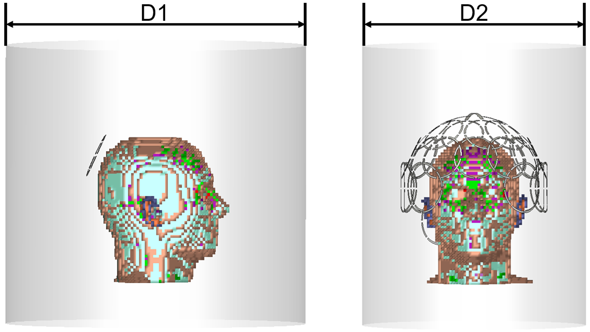
a) Single coil simulation setup. An 80 mm diameter loop coil was placed at the back of the 5mm×5mm×5mm Duke head model, which was positioned at the isocenter of a 500 mm long RF shield for different diameter values (D1= 345 mm, 365 mm, 385 mm, then increased from 400 mm to 640 mm by 20 mm steps) in diameter; b) Setup for the 10.5 T head coil simulations. An encircling 32-channel receive loop array was simulated by varying the diameter of the RF shield (D2 = 345 mm, 400 mm and 640 mm).
Single coil simulations
For the first series of simulations, we modeled an 80 mm-diameter loop coil with 3 mm conductor width. The coil was placed at the back of the head model, tilted by 30 degrees to conform to the curvature of the head, ensuring at least 20 mm between the conductor and the head (Figure 1a). The coil was segmented by inserting eight 4 mm gaps evenly distributed on the coil. Six gaps were connected with fixed capacitors, whereas the remaining two gaps, opposite to each other, were each connected to a 50 Ohm port for matching and tuning, respectively, in co-simulation. The capacitance was the same for all fixed capacitors and was updated at each simulation to ensure that the individual values were similar to the tuning capacitance at the port in co-simulation, to obtain an evenly distributed surface current on the coil for all field strengths and simulation setups. The head model was placed at the isocenter of a local cylindrical RF shield. The RF shield was modeled with 500 mm length and 12 different diameters. In particular, we used 345 mm, 365 mm, 385 mm, and then from 400 mm to 640 mm we uniformly increased the diameter by 20 mm steps. All setups were simulated for main magnetic field strength equal to 3 T (123.2 MHz), 7 T (297.2 MHz), 9.4 T (400 MHz), 10.5 T (447.06 MHz), 11.7 T (498.15 MHz), and 14 T (594.5 MHz). For the 14 T case, additional diameter values were simulated, extending the range from 305 mm to 920 mm, in order to include more than one RF wavelength. The 14 T simulation was repeated after moving the coil 20 mm away from the head model, which constrained the smallest possible shield diameter to be 325 mm in this case. The calculated EM field was exported and the SNR of the loop coil for every voxel of the head model was estimated by dividing the absolute value of the receive sensitivity by the square root of the intrinsic noise power, estimated as the integral over all voxels of the product of the electric conductivity and the absolute value squared of the electric field (σ |E|2). The SNR estimation was performed in Matlab (The MathWorks, Natick, MA, USA).
10.5T 32-channel receive head coil simulations
We simulated a 32-channel receive head coil (Figure 1b), arranging its elements on the surface of a holder consisting of a 240 mm-diameter half sphere and a cylinder with 240 mm diameter and 160 mm length. The array consisted of two crossed dipoles (105 mm in length and 5 mm in width) at the top of head, followed by one row of 6 loops (84 mm in diameter), a second row with 12 loops (84 mm in diameter), a third row of 10 loops (90 mm in diameter). While the first two rows encircled the head, the third row had an opening in the front to avoid covering the face. Two additional 90 mm loops were placed at the back of the head to cover the low brain stem region. Geometric overlap was used to decouple adjacent loop elements (22,23). Each loop was evenly segmented with 8 gaps. Fixed capacitors were then placed on 6 of the gaps for tuning. For identical coils, all fixed capacitors had the same capacitance, which was determined by simulating single 84 mm and 90 mm loops. A 50 Ohm port was placed in each of the two remaining gaps, then one port was used for tuning and the other one for matching in the co-simulation environment. Simulations for individual coil elements of the array were performed separately, leaving one gap open in each of the other coil elements to mimic preamplifier decoupling (22). Simulations were repeated by placing the head model at the isocenter of a RF shield for three different diameters, corresponding to available design options currently under considerations for the integration of a 32-channel receive coil within the head gradient insert of a 10.5 T MR system. In particular, we simulated a 640 mm diameter RF shield lining the inner surface of the body gradient, a 400 mm diameter shield lining the inner surface of the insertable head gradient, and a 345 mm diameter minimum diameter shield intended to be positioned just inside the head bore liner. The length of the RF shield was 500 mm in all cases.
To evaluate eventual shielding effects associated with the use of an external transmit array on the receive array performance, the 32-channel head coil was placed inside a transmit array (14), where all lumped elements had been removed. The transmit array was designed on a 320 mm-diameter cylindrical substrate (εr = 1, σ = 0 S/m), and consisted of 15 rectangular coils (85 mm × 115 mm), arranged in two staggered rows (45 degrees offset between the two rows) with 8 coils on the top row and 7 on the bottom row. The two rows were separated by a 20 mm gap in z direction. Each coil was segmented with 16 evenly distributed gaps. The conductor width of the transmit elements was set to 6 mm and 12 mm in two different simulation setups. The receive array together with the integrated external transmit array were placed at the isocenter of the 400 mm diameter RF shield for the simulation.
Electric and magnetic fields were exported from CST for each coil. The electric fields were employed to calculate the intrinsic noise covariance matrix (22,24), the magnetic field to calculate the receive coil sensitivities. The SNR was then estimated at every voxel using the following optimal matching filter combination of the coils’ contributions (22,24), as a metric to compare relative array performance for the different simulation setups.
| (1) |
where M0 is the equilibrium magnetization, ω0 is the Larmor frequency, S (rn) is a vector that contains the complex-valued receive sensitivities associated with each coil at the target voxel position rn, the superscript H indicates the conjugate of the transpose. ψ is the noise covariance matrix that accounts for coupling effects between the coils, whose elements were calculated as
| (2) |
where the indices m and, m′ indicate the coil elements, V is the voxel volume, the sum is performed over all voxels (Nvoxels) of the model, σ is the electric conductivity, E is the electric field and the superscript * indicates the complex conjugate.
RESULTS
Figure 2 shows the SNR of the single coil, averaged over all voxels of the head model, as a function of the shield diameter. At 3 T and 7 T, the SNR monotonically increased with the size of the shield. At higher magnetic field strengths, the SNR peaked for a particular value of the shield diameter: 465 mm, 420 mm, 378 mm and 345 mm, for B0 = 9.4 T, 10.5 T, 11.7 T and 14 T, respectively. At 14T, the SNR reached a minimum for shield diameter between 440 mm and 540 mm, with the middle point at 490 mm, and began to grow again for larger diameters. After extending the 14 T plot to include diameters of the RF shield between 305 mm and 920 mm (covering two wavelengths at 14 T in free space), the SNR exhibited an undulatory behavior (Figure 3a). In particular, the highest SNR corresponded to the smallest diameter (305 mm), and then the SNR oscillated between minima and maxima. The distance between a SNR minimum and the following SNR maximum, as well as their amplitudes, decreased for larger shield diameters. After the RF coil was moved additional 20 mm away from the head model, to weaken the perturbation due to the head model, the SNR behavior as a function of the shield diameter followed the curvature of a Bessel function (Figure 3b). Note that the location of the minima and maxima remained the same as for Figure 3a, which means that the particular position of the coil element had no effects on the values of the shield diameter that optimize SNR. Figure 4 shows the EM field distribution and B1– created by the single coil element at 10.5 T for the three 32-channel array setups in Figure 1b. We can see that the EM field was local for the small shield diameter (345 mm) that yielded the lowest SNR (Figure 2d), whereas when the diameter was large enough to allow the propagation of the first cylindrical resonant mode, the EM field traveled along the RF shield and was reflected back at the opening due to the impedance mismatching, resulting in overall higher SNR.
Figure 2. Average coil SNR within the head model as a function of the RF shield diameter.
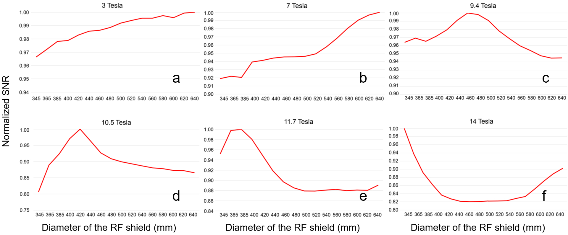
The SNR of the setup in Figure 1 was calculated for shield diameters ranging from 345 mm to 640 mm, and at the MR frequencies of 3T (a), 7 T (b), 9 T (c), 10.5 T (d), 11.7 T (e) and 14 T (f). SNR values were normalized by the maximum SNR for each plot independently.
Figure 3. Average SNR of the single coil element vs the diameter of the RF shield at 14 T.
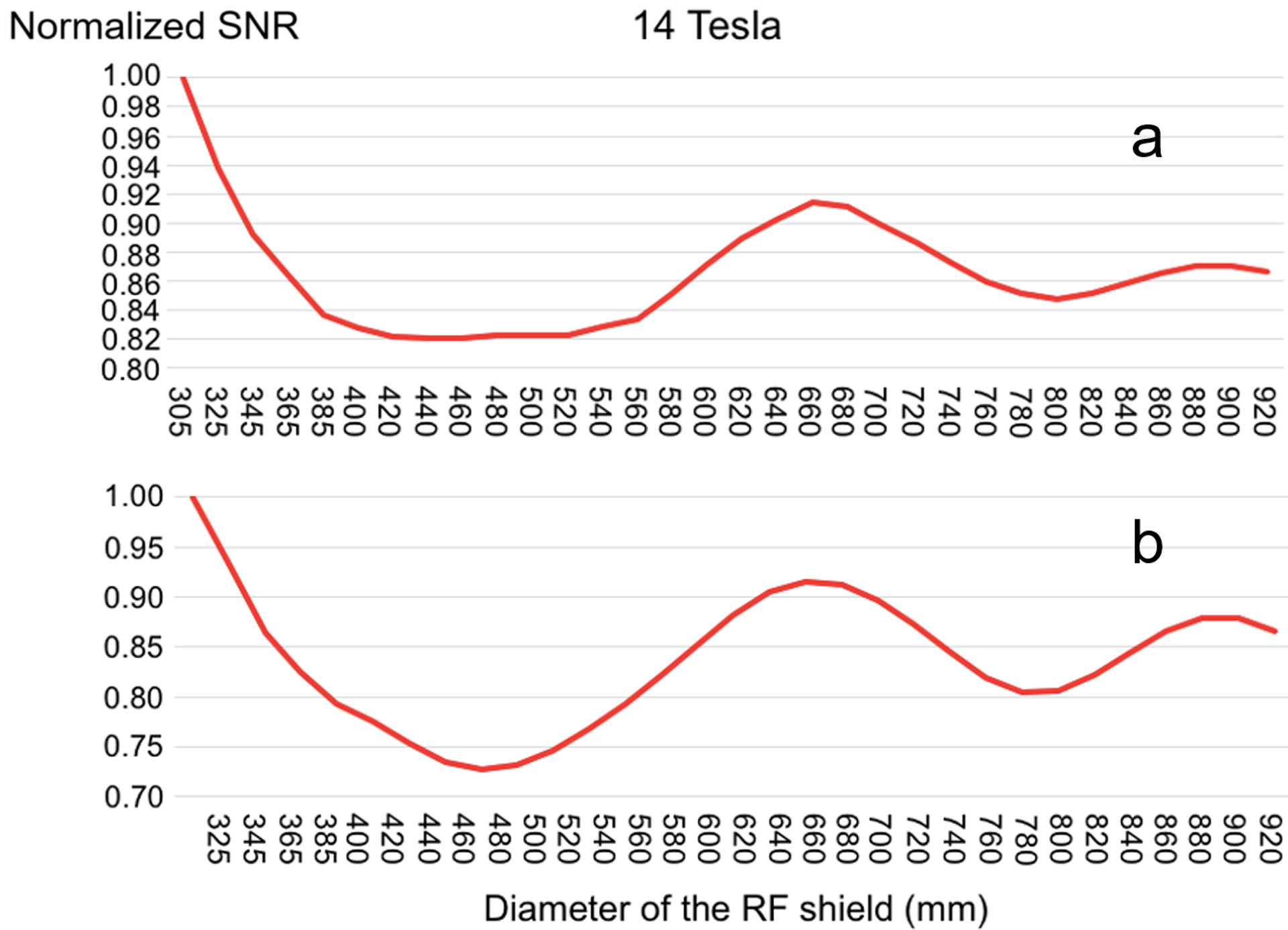
A similar behavior was observed both when the coil was close-fitting (a) or moved 20 mm away from the head model (b) to reduce the perturbation due to the head. In the latter case, the smallest shield diameter was increased to 325 mm to enclose both the coil and the sample at the isocenter. SNR was normalized by its maximum value for each plot independently.
Figure 4. Amplitude of the electromagnetic field E and H, as well as B1− generated by the single coil at 10.5T for different sizes of the RF shield respectively.
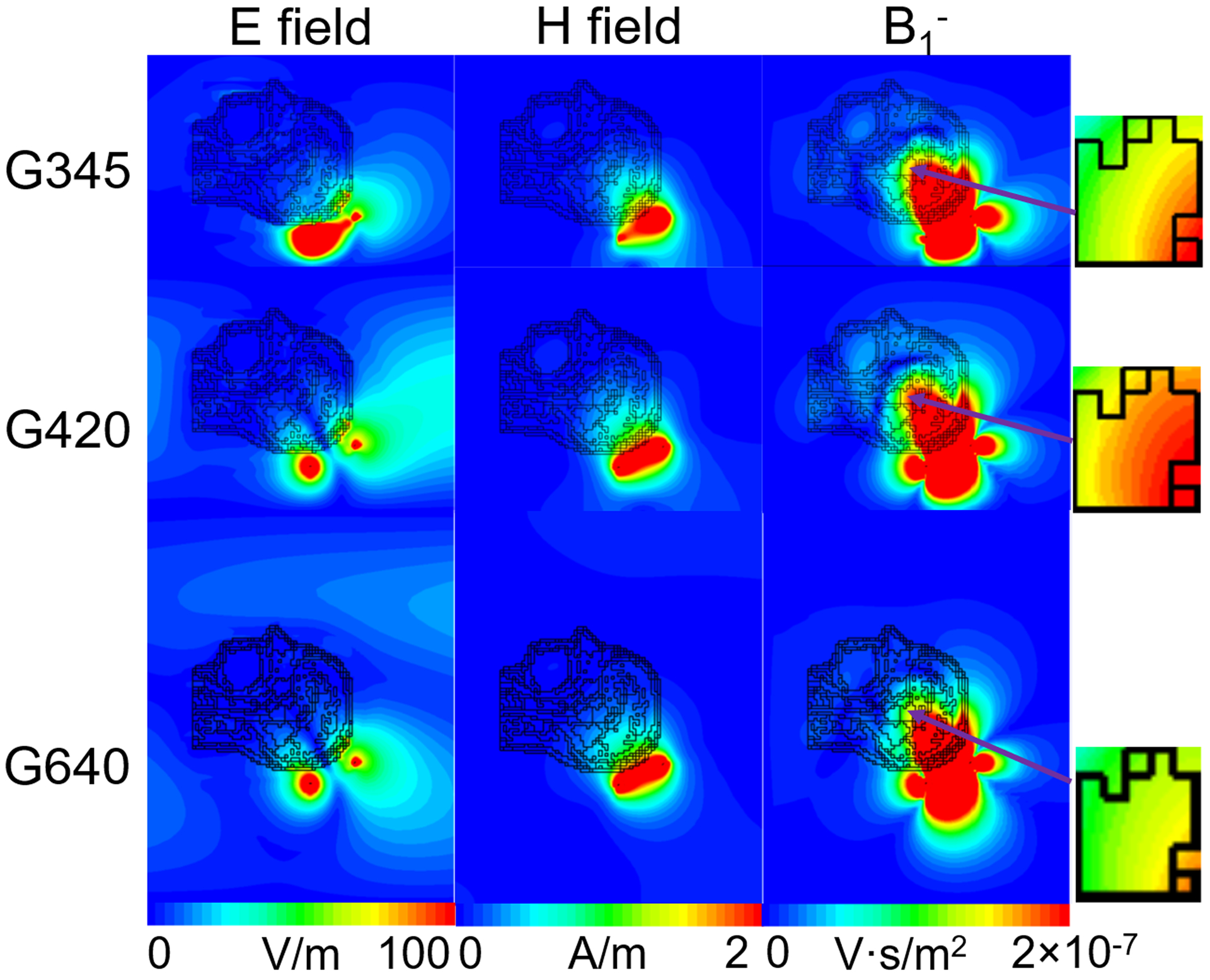
For the smallest shield (G345), the field was locally distributed near the coil, whereas for the larger diameters (G400 and G640) the RF shield acted as a cylindrical resonator, allowing field propagation and reflection at its open end.
Figure 5 compares the SNR of the 10.5 T 32-channel head array for the three different RF shield sizes in Figure 1b. As suggested by the single coil simulations (Figure 2d), a shield diameter of 400 mm yielded higher SNR than both smaller and larger diameters. In particular, the average SNR inside the head was 17% and 27% times larger than when the shield diameter was 345 mm and 640 mm, respectively. Moreover, when the diameter of the RF shield was 400 mm, a resonance effect created a SNR hotspot at the center of the head, in addition to a substantial SNR increase in the peripheral region. As a result, the central SNR was 1.6 and 2.03 times higher for the 400 mm diameter compared to 345 mm and 640 mm diameters, respectively.
Figure 5. SNR maps for the 32-channel head array for different sizes of the RF shield.
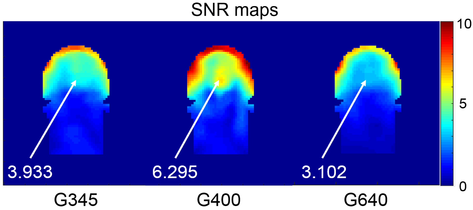
Images in SNR units for a central coronal section of the head model are compared for shield diameter equal to 345 mm, 400 mm and 640 mm. The SNR at the center of the brain is reported for each case.
Figure 6 shows how the SNR of the 32-channel head array for the case of the 400 mm diameter shield was affected by the presence of a 15-channel detuned transmit array arranged on a 320 mm-diameter cylindrical former. When the copper width in the transmit array was 6 mm, central SNR dropped by approximately 30%. When the copper width was doubled, the central SNR dropped even further, becoming 50% of the SNR in case without the transmit array. Note that the SNR hotspot at the center of the head disappeared when the transmit array was included.
Figure 6. Effect of the encircling transmit array on the SNR of the 32-channel receive array.
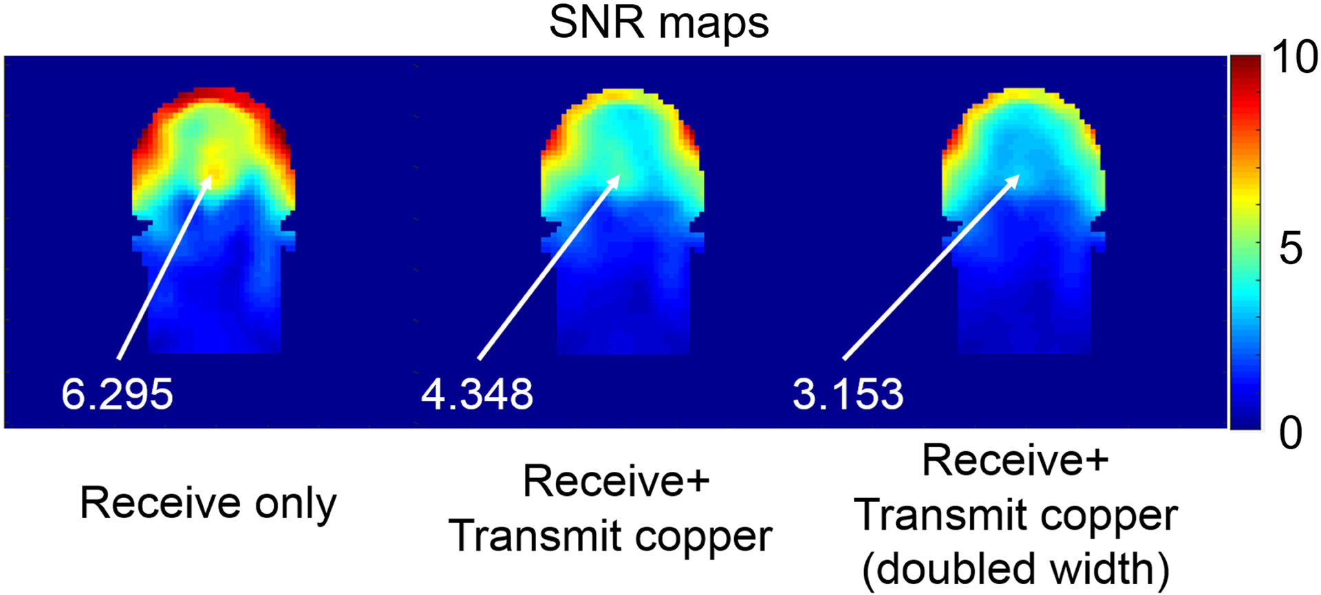
Images in SNR units for a central coronal section of the head are compared for the cases with the receive array alone (left), combined with a 15-channel detuned transmit array with 6 mm (middle) and 12 mm (right) conductor width. The transmit array conductors were arranged on a 320 mm-diameter cylindrical former surrounding the head and placed at the isocenter of a 400 mm diameter RF shield.
DISCUSSION
In UHF MRI systems where the RF wavelength is smaller than the human-sized sample, traditional RF array designs are not necessarily optimal in terms of SNR. For example, theoretical (25,26) and experimental (27–32) work has shown that novel RF coil designs are needed to fully exploit the potential of UHF MRI. In this work we instead investigated how the design of the RF shield can affect the performance of receive coils at UHF. While for field strengths ≤ 7 T, we confirmed the validity of the standard design approach of placing the RF shield as far as possible from detector coils, we found that at higher field strength, an optimal size for the shield exists within the space allowed by the bore of the MR scanner. This is due to the fact that, at sufficiently high frequency, the RF shield behaves as a cylindrical waveguide and contributes to the total EM field detected by the receive coils. For a length of 50 cm, the optimal shield diameter that maximized SNR for a single was about 470 mm and 420 mm at 9.4 T and 10.5 T, respectively (Figure 2). Note that the ratio of these two optimal diameters is 1.12, which is also the ratio of the operating frequencies of the two field strengths (10.5 T/9.4 T). This is consistent with the cylindrical resonator theory, in which the diameter of the waveguide is inversely proportional to the resonance frequency of the first mode (33). As a result, the optimal shield diameter is inversely proportional to the main magnetic field strength.
It is worth noting that the length of the shield could affect such proportion. In this work, we set the absorbing boundary right at the open end of the RF shield to eliminate reflection due to characteristic impedance mismatch. This allowed us to focus on the shield diameter, without having to consider the effect of its length. While allowing reflection from the end of the shield would have a minor effect on our results because more than 99% of the RF power is absorbed by the sample, this effect should instead be modeled in the case of smaller loads, when a non-negligible amount of power would be reflected. In such case, the optimal diameter of the RF shield would likely depend on its length, since constructive and destructive interferences between forward and reflected EM waves would happen at different positions depending on the RF wavelength.
Our setup in Figure 1a included only the head of the Duke model to enable us to position the model at the center of the RF shield for all diameters considered in our simulations. Such truncation has an effect on the propagation of the EM field within the shield. However, when we included also the shoulders in the simulation, which required moving the model away from the center of the RF shield, we found that the results were minimally affected (Figure 7). In particular, the overall trend for 10.5 T was the same as in Figure 2d, but the optimal shield diameter decreased from 420 mm to 400 mm, with a minor effect on the SNR.
Figure 7. Average SNR within the head model for a loop coil as a function of the RF shield diameter at 10.5 T.
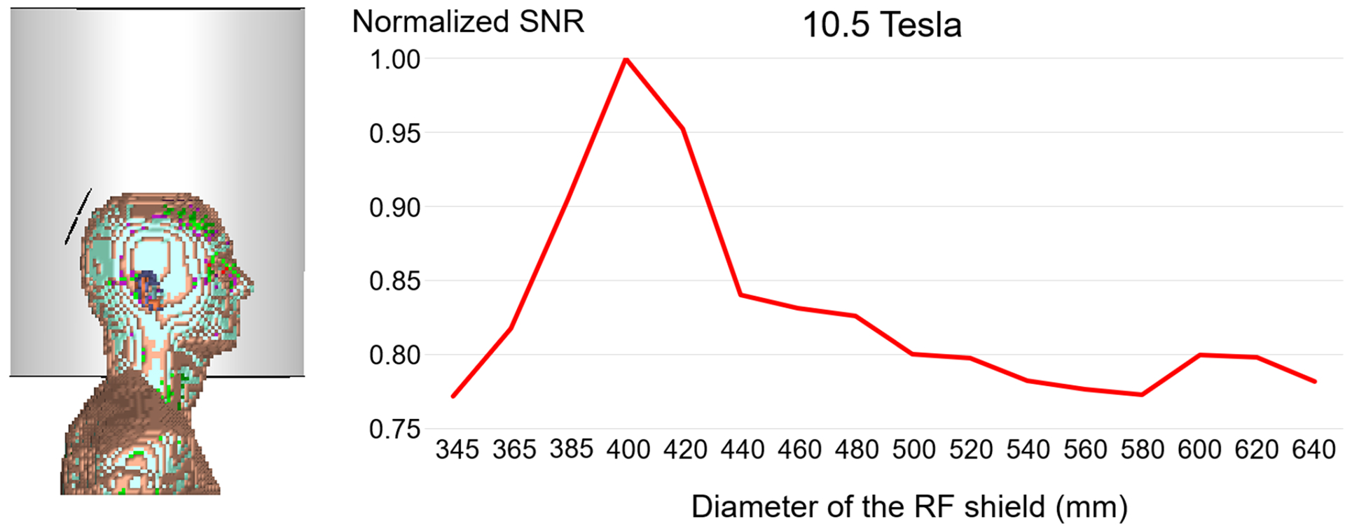
An 80 mm diameter loop coil was placed at the back of the head of the 5mm×5mm×5mm Duke anatomical model, which included head, neck and shoulders. The setup was positioned inside a 500 mm long RF shield, shifted from isocenter to accommodate the shoulders in all simulated cases. The coil was tuned for 10.5 T and the average SNR within the head was calculated for different diameters of the RF shield (D1= 345 mm, 365 mm, 385 mm, then increased from 400 mm to 640 mm by 20 mm steps). SNR values were normalized by the maximum SNR.
For the case of traveling wave MRI (6) the highest transmit efficiency is associated with a bore diameter that is equal to or barely larger than the size that supports the cut-off frequency of the first traveling wave mode (12). For the case of the RF shield resonating effect described above, the SNR begins to increase after the shield size allows the first resonant mode, which is a transverse electrical mode (TE11) (8–10,12,34) and reaches its maximum before the second mode, which is a transverse magnetic (TM01) mode, kicks in. At the same time it is still desirable to place the shield far from the coil to reduce inductive losses, conforming to 3 T and 7 T cases in Figure 2, but not far enough to support higher-order modes, which would negatively affect SNR by increasing the electric field within the sample. Unlike the traveling wave system, where the basic mode is excited from the open end of the scanner and, therefore, its cutoff frequency depends only on the diameter of the empty bore, for the local resonating system created by the cylindrical shield, the cutoff frequencies depend also on the dielectric properties of the object inside. Therefore, due to the inhomogeneous load within the shield, the cutoff frequency for the second resonant mode cannot be analytically calculated for MRI applications, but one could still predict a suitable shield geometry with full-wave electrodynamic simulations. For example, based on the equivalence between the ratio of main magnetic field strengths and the ratio of the optimal shield diameters (see above), using the 10.5 T results, we could estimate that the optimal shield diameter should be approximately 377 mm and 307.5 mm at 11.7 T and 14 T, respectively. These values are, in fact, in agreement with the diameters associated with the largest SNR in the corresponding plots in Figure 2. Note that the optimal shield diameter derived from the single coil simulation was similar to the diameter that yielded the largest SNR for the 32-channels array. While this suggests that single coil simulations can provide reasonable predictions, simulations with the full array are needed to account for interactions between coil elements and accurately estimate the shield size that maximizes SNR.
We showed that at UHF the behavior of the SNR as a function of the diameter of the RF shield follows the curvature of a Bessel function (Figure 3), which also describes the radial dependency of the EM field inside a cylindrical waveguide (34). This suggests that the RF shield of given dimension indeed acts as a local waveguide that supports resonant modes at UHF. The minima and maxima of the SNR occurred for the same values of the RF shield diameters both when the coil was close and at some distance from the head model, although only in the latter case the curve closely resembled the shape of a Bessel function. This suggests that the overall behavior of the SNR as a function of the shield diameter does not depend on the distance of the RF coil relative to the sample. However, it is worth noting that this particular SNR behavior was only observed when the coil was tilted in the z-direction. In fact, in the single coil simulation setup, when the coil was laid down flat on a cylindrical substrate, in which case its axis was pointing in the left-right direction in Fig. 1a, even at UHF the SNR monotonically increased with the shield diameter. We validated this finding using both numerical simulations with a human head model and full-wave analytic calculations with a uniform cylindrical phantom (25). This result suggests that in order to excite the given resonance mode effectively, a z-component of H field is needed, which is consistent also with the findings in (20).
At 3 T and 7 T, the SNR of the single coil monotonically increased with shield diameter, but it only changed by 4% and 8%, respectively, in the range of shield diameters between 345 mm and 640 mm. In contrast, at higher field strengths, when the RF shield with optimal diameter acted as a resonator at operating frequency, the SNR for a single coil element could change by as much as 20% (Figure 2). In the case of the 10.5 T 32-channel array, the SNR at the center of the head was twice as large for the 400 mm-diameter shield (the optimal value when including the shoulders in the single coil simulation – see Figure 7) than for the more distant 640 mm-diameter shield and 60% larger than for the close-fitting 345 mm-diameter shield. These results show that the size of the RF shield could play a critical role for SNR performance at UHF and, therefore, it should be taken into account when designing coils.
Figure 4 shows that, once the diameter of the RF shield was large enough, a resonating mode appeared and reduced the electric field distribution in the head, while enhancing the B1 field. As a result, the SNR was higher. However, when the shield diameter was considerably larger than the optimal diameter, the electric field increased and seemed to travel around the head, which resulted in lower SNR. This could be explained by the appearance of the second resonant mode, which is a TM01 mode. Due to presence of the dielectric load of the sample, its exact cutoff frequency cannot be calculated analytically to confirm such hypothesis. The high SNR at the center of the head associated with the optimal shield diameter (Figure 5) could be the result of constructive interference created by the TE11 mode of the resonator.
In conclusion, we demonstrated that at sufficiently high magnetic field strength, the design of the local RF coils should be optimized together with the RF shield and to benefit from both near field and resonating effects of the shield. This work provided an insight for choosing the most suitable shield size (i.e., 400 mm diameter), among three potential design choices, for an RF shield that we plan to integrate with a 32-channel receive array and a head gradient system at 10.5 T. Our simulations showed that using a separate transmit array between the RF shield with the optimal diameter and the receive array could considerably reduce SNR, due to the shielding effect of the conductors in the transmit array.
ACKNOWLEDGMENTS
The authors would like to thank Dr. Anke Henning and Dr. Nikolai Avdievich for useful discussions about shielding effects on receive coils. This work was supported in part by NIH U01 EB025144, NIH R01 EB024536, NIH S10 RR029672, NSF 1453675 and Cancer Prevention and Research Institute of Texas RR180056, and was performed under the rubric of the Center for Advanced Imaging Innovation and Research (CAI2R, www.cai2r.net) and CMRR, National Centers for Biomedical Imaging and Bioengineering (NIH P41 EB017183 and P41 EB015894).
FUNDING INFORMATION:
National Institutes of Health, Grant/Award Numbers: U01 EB025144, R01 EB024536, R01 EB021277 and P41 EB017183
National Science Foundation (NSF), Grant/Award Number: 1453675
Cancer Prevention and Research Institute of Texas, Grant Number: RR180056
REFERENCES
- 1.Asher KA, Bangerter NK, Watkins RD, Gold GE. Radiofrequency coils for musculoskeletal magnetic resonance imaging. Top Magn Reson Imaging 2010;21(5):315–323. [DOI] [PMC free article] [PubMed] [Google Scholar]
- 2.Handa S, Haishi T, Kose K. Development of a local electromagnetic shielding for an extremity magnetic resonance imaging system. Rev Sci Instrum 2008;79(11):113706. [DOI] [PubMed] [Google Scholar]
- 3.Van Hecke PE, Marchal GJ, Baert AL. Use of shielding to prevent folding in MR imaging. Radiology 1988;167(2):557–558. [DOI] [PubMed] [Google Scholar]
- 4.Ong KC, Wen H, Chesnick AS, Duewell S, Jaffer FA, Balaban RS. Radiofrequency shielding of surface coils at 4.0 T. J Magn Reson Imaging 1995;5(6):773–777. [DOI] [PubMed] [Google Scholar]
- 5.Favazza CP, King DM, Edmonson HA, Felmlee JP, Rossman PJ, Hangiandreou NJ, Watson RE, Gorny KR. Use of a radio frequency shield during 1.5 and 3.0 Tesla magnetic resonance imaging: experimental evaluation. Med Devices (Auckl) 2014;7:363–370. [DOI] [PMC free article] [PubMed] [Google Scholar]
- 6.Brunner DO, De Zanche N, Frohlich J, Paska J, Pruessmann KP. Travelling-wave nuclear magnetic resonance. Nature 2009;457(7232):994–998. [DOI] [PubMed] [Google Scholar]
- 7.DO B, N DZ, Paska J, Frohlich J, KP P Traveling Wave MR on a Whole-Body System. 2008; Toronto, Canada: p p434. [Google Scholar]
- 8.Webb A Cavity- and waveguide-resonators in electron paramagnetic resonance, nuclear magnetic resonance, and magnetic resonance imaging. Prog Nucl Magn Reson Spectrosc 2014;83:1–20. [DOI] [PubMed] [Google Scholar]
- 9.Geschewski FH, Brenner D, Felder J, Shah NJ. Optimum coupling and multimode excitation of traveling-waves in a whole-body 9.4T scanner. Magn Reson Med 2013;69(6):1805–1812. [DOI] [PubMed] [Google Scholar]
- 10.Hoffmann J, Mirkes C, Shajan G, Scheffler K, Pohmann R. Combination of a multimode antenna and TIAMO for traveling-wave imaging at 9.4 Tesla. Magn Reson Med 2016;75(1):452–462. [DOI] [PubMed] [Google Scholar]
- 11.Webb AG, Collins CM, Versluis MJ, Kan HE, Smith NB. MRI and localized proton spectroscopy in human leg muscle at 7 Tesla using longitudinal traveling waves. Magn Reson Med 2010;63(2):297–302. [DOI] [PMC free article] [PubMed] [Google Scholar]
- 12.Zhang B, Sodickson DK, Lattanzi R, Duan Q, Stoeckel B, Wiggins GC. Whole body traveling wave magnetic resonance imaging at high field strength: homogeneity, efficiency, and energy deposition as compared with traditional excitation mechanisms. Magn Reson Med 2012;67(4):1183–1193. [DOI] [PMC free article] [PubMed] [Google Scholar]
- 13.Zhao W, Cohen-Adad J, Polimeni JR, Keil B, Guerin B, Setsompop K, Serano P, Mareyam A, Hoecht P, Wald LL. Nineteen-channel receive array and four-channel transmit array coil for cervical spinal cord imaging at 7T. Magn Reson Med 2014;72(1):291–300. [DOI] [PMC free article] [PubMed] [Google Scholar]
- 14.Shajan G, Kozlov M, Hoffmann J, Turner R, Scheffler K, Pohmann R. A 16-channel dual-row transmit array in combination with a 31-element receive array for human brain imaging at 9.4 T. Magn Reson Med 2014;71(2):870–879. [DOI] [PubMed] [Google Scholar]
- 15.Zhang B, Seifert AC, Kim JW, Borrello J, Xu J. 7 Tesla 22-channel wrap-around coil array for cervical spinal cord and brainstem imaging. Magn Reson Med 2017;78(4):1623–1634. [DOI] [PubMed] [Google Scholar]
- 16.Rietsch SHG, Orzada S, Maderwald S, Brunheim S, Philips BWJ, Scheenen TWJ, Ladd ME, Quick HH. 7T ultra-high field body MR imaging with an 8-channel transmit/32-channel receive radiofrequency coil array. Med Phys 2018;45(7):2978–2990. [DOI] [PubMed] [Google Scholar]
- 17.Oezerdem C, Winter L, Graessl A, Paul K, Els A, Weinberger O, Rieger J, Kuehne A, Dieringer M, Hezel F, Voit D, Frahm J, Niendorf T. 16-channel bow tie antenna transceiver array for cardiac MR at 7.0 tesla. Magn Reson Med 2016;75(6):2553–2565. [DOI] [PubMed] [Google Scholar]
- 18.Finnerty M, Yang X, Zheng T, Heilman J, Castrilla N, Herczak J, Fujita H, Ibrahim TS, Boada F, Zhao T, Schmitt F, Stoeckel B, Potthast A, Wicklow K, Trattnig S, Mamisch C, Recht M, Sodickson D, Wiggins G, Zhu Y. A 7-Tesla High Density Transmit with 28-Channel Receive-Only Array Knee Coil. Proc Int Soc Magn Reson Med Sci Meet Exhib Int Soc Magn Reson Med Sci Meet Exhib 2010;2010:642. [PMC free article] [PubMed] [Google Scholar]
- 19.Adriany G, Auerbach EJ, Snyder CJ, Gozubuyuk A, Moeller S, Ritter J, Van de Moortele PF, Vaughan T, Ugurbil K. A 32-channel lattice transmission line array for parallel transmit and receive MRI at 7 tesla. Magn Reson Med 2010;63(6):1478–1485. [DOI] [PMC free article] [PubMed] [Google Scholar]
- 20.Avdievich NI, Solomakha G, Ruhm L, Bause J, Scheffler K, Henning A. Bent folded-end dipole head array for ultrahigh-field MRI turns “dielectric resonance” from an enemy to a friend. Magn Reson Med 2020. [DOI] [PubMed] [Google Scholar]
- 21.Christ A, Kainz W, Hahn EG, Honegger K, Zefferer M, Neufeld E, Rascher W, Janka R, Bautz W, Chen J, Kiefer B, Schmitt P, Hollenbach HP, Shen J, Oberle M, Szczerba D, Kam A, Guag JW, Kuster N. The Virtual Family--development of surface-based anatomical models of two adults and two children for dosimetric simulations. Phys Med Biol 2010;55(2):N23–38. [DOI] [PubMed] [Google Scholar]
- 22.Roemer PB, Edelstein WA, Hayes CE, Souza SP, Mueller OM. The NMR phased array. Magn Reson Med 1990;16(2):192–225. [DOI] [PubMed] [Google Scholar]
- 23.Wiggins GC, Triantafyllou C, Potthast A, Reykowski A, Nittka M, Wald LL. 32-channel 3 Tesla receive-only phased-array head coil with soccer-ball element geometry. Magn Reson Med 2006;56(1):216–223. [DOI] [PubMed] [Google Scholar]
- 24.Lattanzi R, Grant AK, Polimeni JR, Ohliger MA, Wiggins GC, Wald LL, Sodickson DK. Performance evaluation of a 32-element head array with respect to the ultimate intrinsic SNR. NMR Biomed 2010;23(2):142–151. [DOI] [PMC free article] [PubMed] [Google Scholar]
- 25.Lattanzi R, Sodickson DK. Ideal current patterns yielding optimal signal-to-noise ratio and specific absorption rate in magnetic resonance imaging: computational methods and physical insights. Magn Reson Med 2012;68(1):286–304. [DOI] [PMC free article] [PubMed] [Google Scholar]
- 26.Pfrommer A, Henning A. On the Contribution of Curl-Free Current Patterns to the Ultimate Intrinsic Signal-to-Noise Ratio at Ultra-High Field Strength. NMR Biomed 2017;30(5). [DOI] [PubMed] [Google Scholar]
- 27.Steensma BR, Voogt IJ, Leiner T, Luijten PR, Habets J, Klomp DWJ, van den Berg CAT, Raaijmakers AJE. An 8-channel Tx/Rx dipole array combined with 16 Rx loops for high-resolution functional cardiac imaging at 7 T. MAGMA 2018;31(1):7–18. [DOI] [PMC free article] [PubMed] [Google Scholar]
- 28.Avdievich NI, Giapitzakis IA, Pfrommer A, Borbath T, Henning A. Combination of surface and ‘vertical’ loop elements improves receive performance of a human head transceiver array at 9.4 T. NMR Biomed 2018;31(2). [DOI] [PubMed] [Google Scholar]
- 29.Erturk MA, Raaijmakers AJ, Adriany G, Ugurbil K, Metzger GJ. A 16-channel combined loop-dipole transceiver array for 7 Tesla body MRI. Magn Reson Med 2017;77(2):884–894. [DOI] [PMC free article] [PubMed] [Google Scholar]
- 30.Raaijmakers AJ, Italiaander M, Voogt IJ, Luijten PR, Hoogduin JM, Klomp DW, van den Berg CA. The fractionated dipole antenna: A new antenna for body imaging at 7 Tesla. Magn Reson Med 2016;75(3):1366–1374. [DOI] [PubMed] [Google Scholar]
- 31.Wiggins G, Zhang B, Cloos M, Lattanzi R, Chen G, Lakshmanan K, Haemer G, Sodickson D. Mixing loops and electric dipole antennas for increased sensitivity at 7 Tesla. ISMRM Salt Lake City, USA: 2013:1. [Google Scholar]
- 32.Raaijmakers AJ, Ipek O, Klomp DW, Possanzini C, Harvey PR, Lagendijk JJ, van den Berg CA. Design of a radiative surface coil array element at 7 T: the single-side adapted dipole antenna. Magn Reson Med 2011;66(5):1488–1497. [DOI] [PubMed] [Google Scholar]
- 33.Pozar DM, ProQuest (Firm). Microwave engineering. Hoboken, NJ: Wiley; 2012. 1 online resource (xvii, 732 pages) p. [Google Scholar]
- 34.Jackson JD. Classical electrodynamics. New York: Wiley; 1999. xxi, 808 p. p. [Google Scholar]


